Abstract
In the research for sustainable construction, cross-laminated timber (CLT) has gained popularity and become a widely used engineered timber product. However, there are few numerical studies of the structural behaviour of CLT. Among other issues, the orthotropic properties of CLT complicate finite element analysis (FEA). This paper presents a finite element model (FEM) to predict the structural behaviour of CLT beams subjected to sustained flexural loading. This numerical model includes a material model based on the orthotropic material properties of different timber species. Furthermore, the orientation and the properties of each layer are considered. Most of the previous studies simulate CLT beams as a homogeneous material. However, in this work the CLT beam is modelled as a composite material made up of five layers with different orientations and properties. Bonded contacts are used to define the interaction between layers. In addition, nonlinearities, such as large displacement, are used to simulate the behaviour of CLT beams. The model provides the load-displacement relationship and stress concentration. Tsai-Wu failure criteria is used in the simulation to predict the failure modes of the CLT beams studied.
1. Introduction
Cross-laminated timber (CLT) beams have become a popular structural element. In the early 1990s, CLT was developed in Austria, Germany and Switzerland. The advantages of CLT include shorter building time and a high strength ratio [1]. CLT beams are composed of wood layers, arranged and glued crosswise as illustrated in Figure 1. CLT beams are commonly made of an odd number of lamellas which form a solid panel. The alternating grain orientation, laminar structure, and capacity to bear in- and out-of-plane loads [2] make it suitable as a wall and floor element.
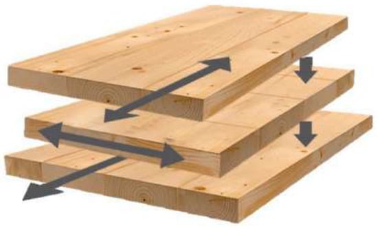
Figure 1.
Cross-laminated timber configuration. (https://www.sfhac.org/mass-timber-wood/).
Due to its orthogonal grain direction and to the anisotropy of wood, the mechanical behaviour of CLT beams is complex. The elastic mechanical properties are different along principal axes, which are the axial direction (grain), the radial direction, and the circumferential direction (i.e., strength and stiffness in the axial direction are larger than those in radial and circumferential direction) [3]. Therefore, to design CLT elements (walls and slabs) the mechanical properties must be understood. Various analytical methods are used to study the mechanical properties and the mechanical behaviour of CLT for both in- and out-of-plane loads [4,5].
Some authors consider CLT as a laminated composite material. Blass [6] developed a methodology for designing CLT panels based on the composite theory. Most of the existing studies are based on 2D plate theories [7]. At present, research is aimed to develop 3D analyses to better understand CLT behaviour.
This study aims to develop a finite element method (FEM) to predict the deformation and the failure mechanism of a CLT panel under perpendicular loads to plane. Experiments conducted in the University of Edinburgh at ambient temperature [8] were used to compare the finite element (FE) results.
2. Finite Element Analysis (FEA)
In order to compare and verify the accuracy of the FE model developed, the boundary conditions at ambient temperature applied in the model were the same as in work [8]. A 3D FE model of one of the CLT beams studied by [8] was developed in ANSYS 18.1.
This FE model analyzed the structural response of a CLT beam under a sustained load. The CLT beam used to develop the model has a 5-layer configuration. The mechanical properties of timber were taken from previous research [8].
Considering the CLT beam as a composite element, it was modelled using the composite module of ANSYS [9]. The FE model developed used solid elements since each of the plies was considered as a thick element. Elastic material properties were assigned in each orthogonal direction of the layer. Other assumptions are: layers are perfectly bonded together and the material properties of each layer are constant through the thickness.
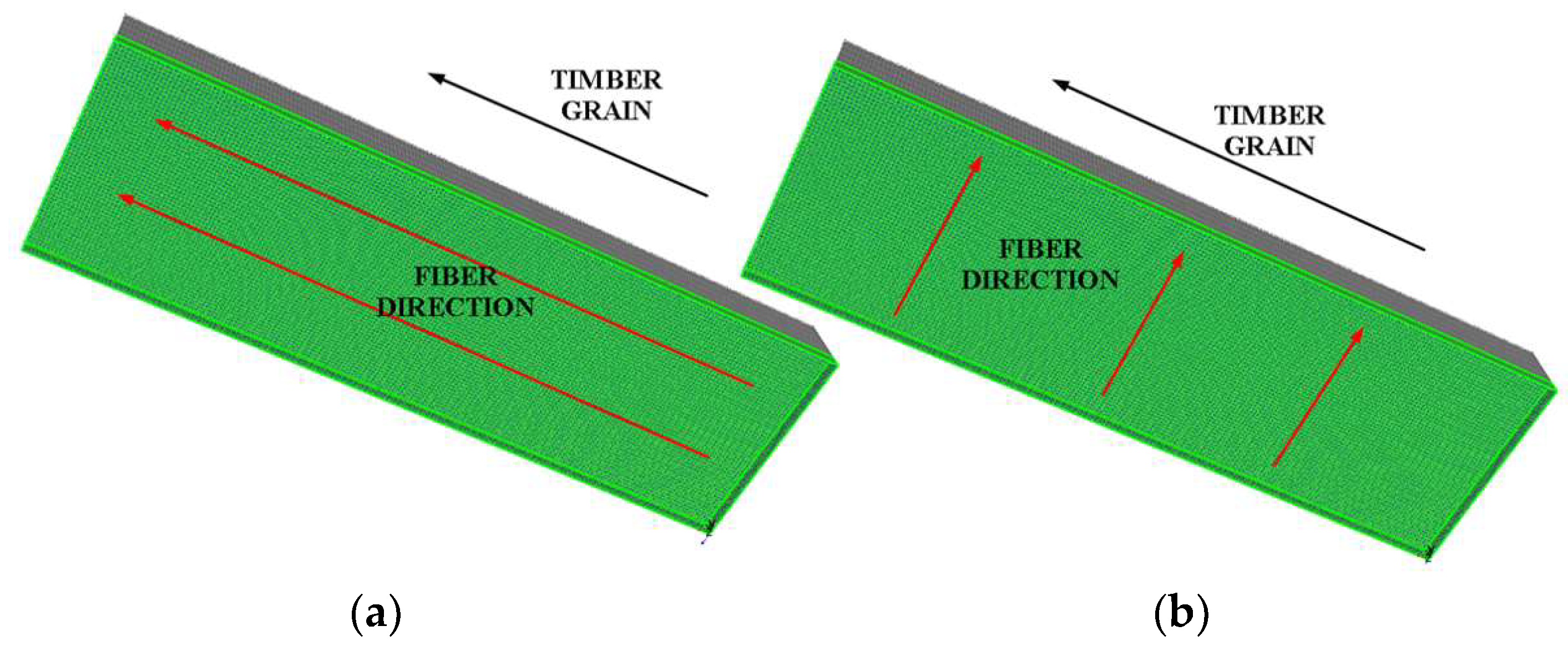
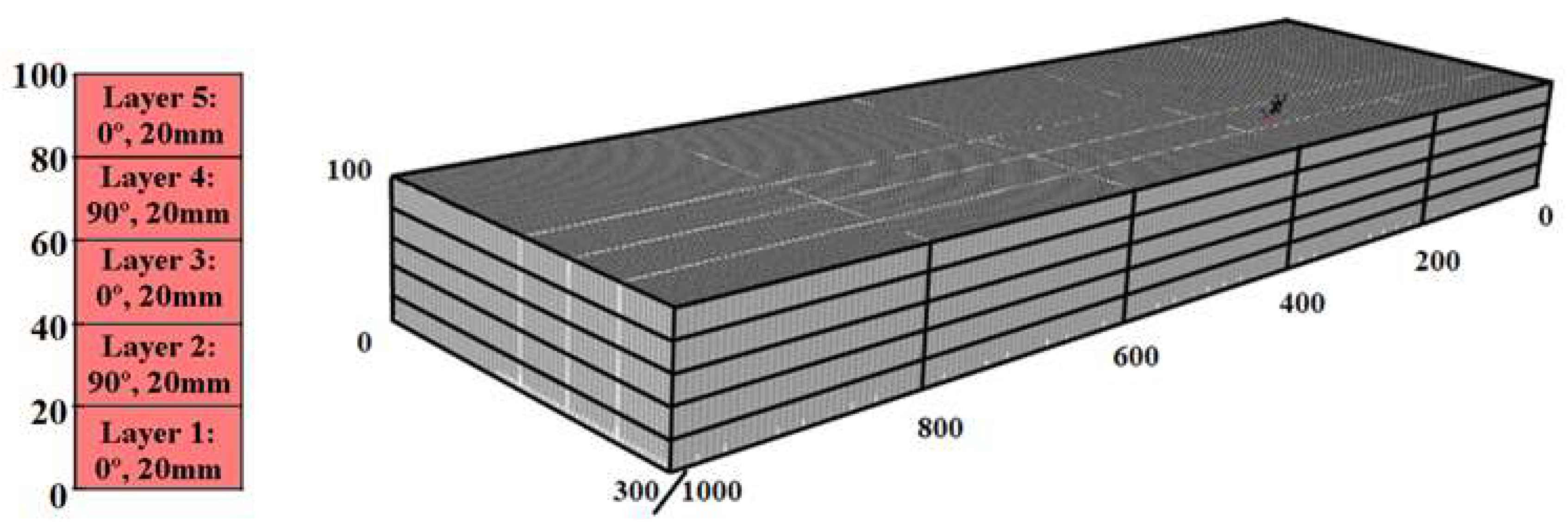
The configuration of the model in different layers was the same as the real configuration. The 5-layer configuration used was: 20(l) + 20(p) + 20(l) + 20(p) + 20(l) mm. Where l and p means longitudinal and perpendicular grain direction, as shown in Figure 2.

Figure 2.
Grain direction of the layers. (a) fibre parallel to grain (longitudinal grain direction); (b) fibre perpendicular to grain (perpendicular grain direction).
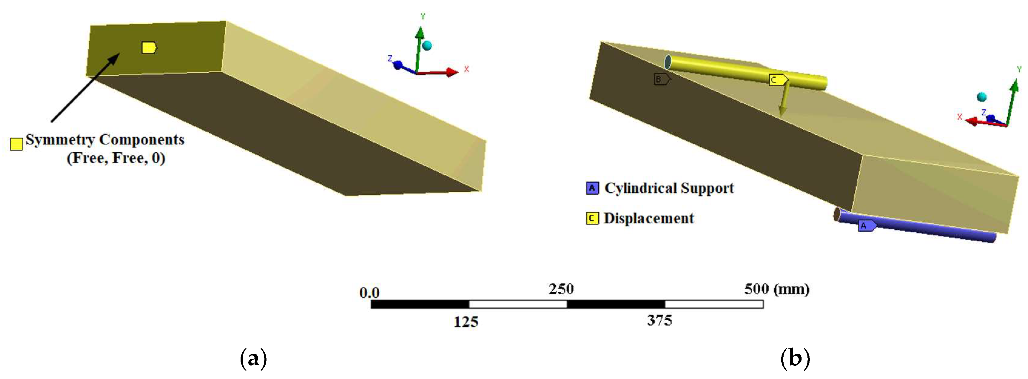
The CLT model was 1000 mm long, 300 mm wide, and 100 mm thick, as shown in Figure 3. In order to reduce the computational cost, a simplified model using conditions of symmetry is used, (Figure 4). The symmetry conditions were applied in the longitudinal direction. These conditions reduce the size of the numerical model.

Figure 3.
Model dimensions.

Figure 4.
(a) Symmetry conditions applied in the model; (b) Boundary conditions applied in the model.
Each ply was modelled using 8-node solid elements (SOLID 186). The main features of the mesh for the model are shown in Table 1.

Table 1.
FE mesh properties.
Boundary conditions applied in this simulation are the same as in experimental tests. These conditions are the following:
The Tsai Wu failure criterion was used in ACP-Post to evaluate the margin to failure. This criterion is useful to evaluate mechanical behaviour in timber elements due to its different strengths in compression and tension [10].
3. Results
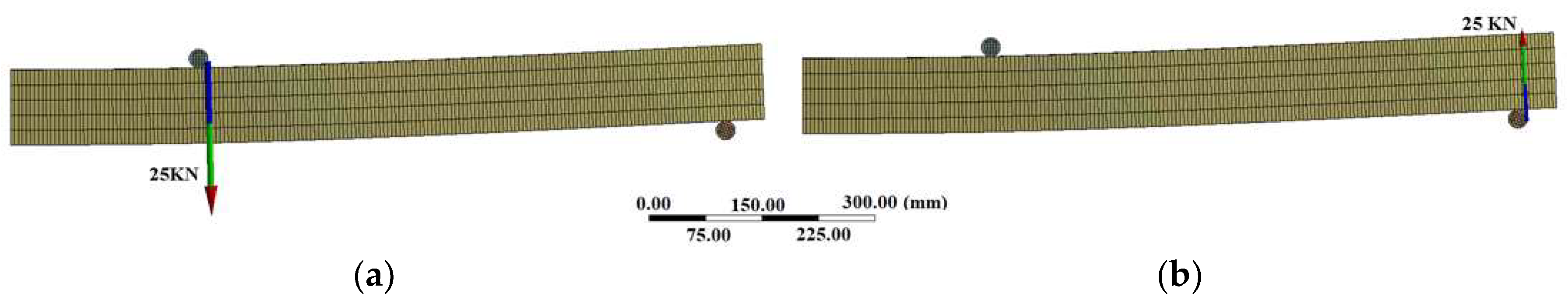
The numerical and the experimental results are compared to validate the numerical model. The displacement applied to the beam generates a reaction load (Figure 5). This load is equal to the load applied in the experimental tests.
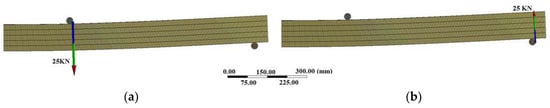
Figure 5.
Force reaction. (a) Load roller; (b) Support.
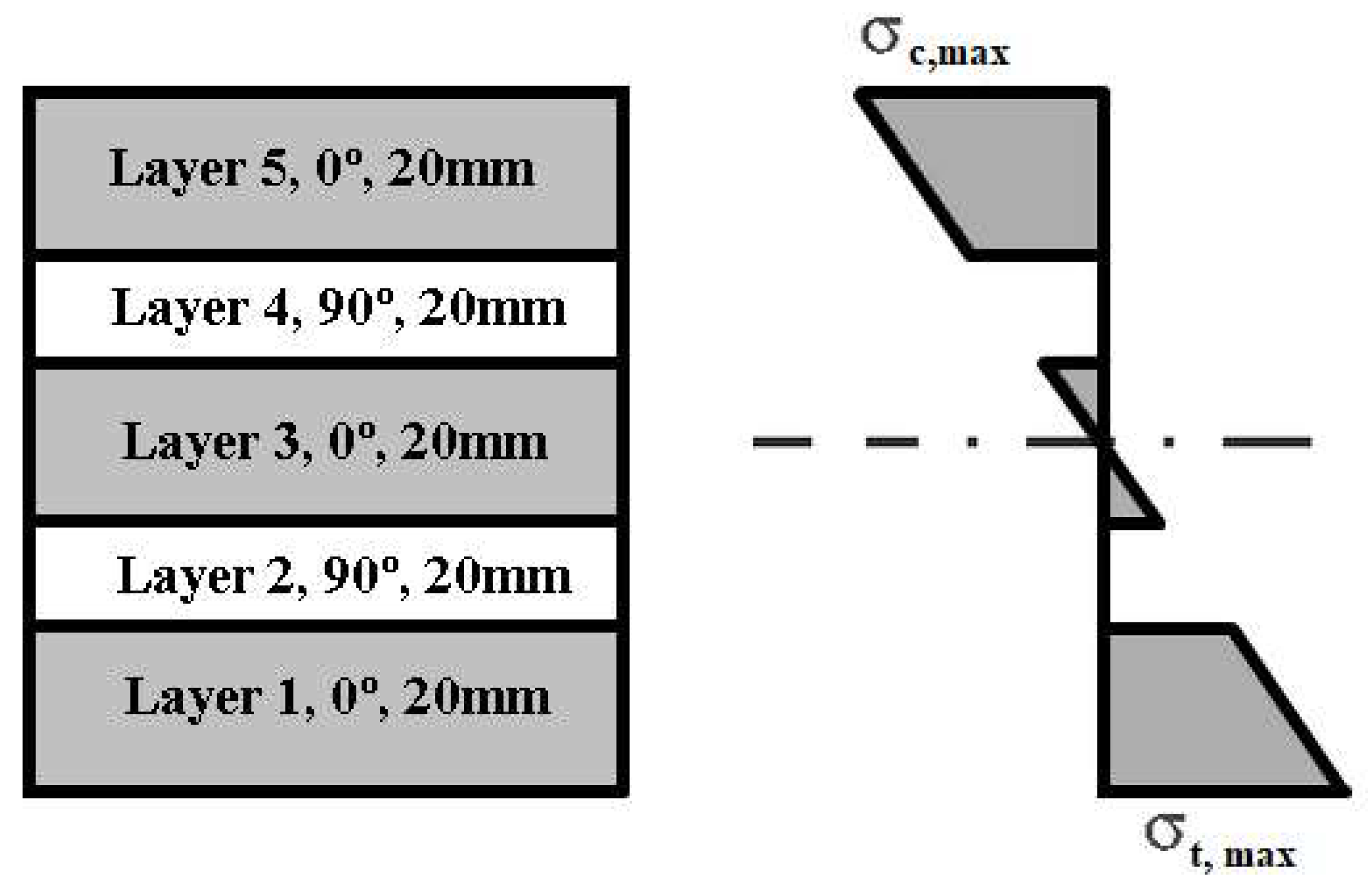
The ACP-Post module plots the stresses and failure modes of the numerical beam model. As this model was developed with solid elements, the stress is plotted at the top and bottom of each layer.
The stress distribution is shown in Figure 6, which has the same form as the stress diagrams for CLT beams in other works [2,4].
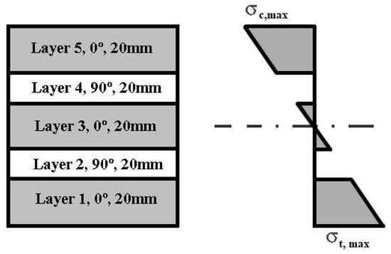
Figure 6.
CLT beam stress distribution of a five-layer cross section loaded out-of-plane.
Failure distribution of the different layers using Tsai-Wu failure criterion is plotted in Figure 7. The failure values used in this work indicate the margin to failure. The range of zero to one is not critical. However, above that range the values are critical.
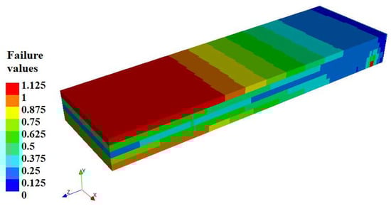
Figure 7.
Failure distribution of a five-layer CLT beam (Tsai-Wu failure criterion).
4. Conclusions
This work represents the first step to analyze the structural behaviour of a CLT beam by using finite elements. This procedure uses ANSYS Composite PrePost and provides the tools to study CLT beam as a composite element. Furthermore, the flexibility of the model in the design of the fibre orientation of each layer makes it possible to assess the ultimate limit state of the CLT beams.
The Tsai-Wu failure criterion provides the failure values for each layer. This criterion predicts failure when the failure index reaches 1. For the model developed in this work, the Tsai-Wu failure criterion predicts the failure of layer 1 and layer 5 under a sustained load. The failure distribution in the FE model is in good agreement with the experimental results. The tensile stress limits are exceeded in layer 1 and the compression stress limits are exceeded in layer 5.
The 3D model developed in this work provides accurate out-of-plane stress results. Further work includes providing an adequate structural FE model with valid failure criteria for each layer.
Author Contributions
J.E.M.-M., M.A.-M., F.P.Á.R. and J.J.d.C.D. conceived and designed the experiments, analyzed the data; contributed analysis tools and wrote the paper.
Acknowledgments
The authors of this article are grateful to BRE Centre for Fire Safety Engineering at the University of Edinburgh for the experimental data and the technical support. Finally, thanks to Swanson Analysis Inc. for the use of the university research version of the ANSYS v 18.1 program in this paper. This work was partially financed by the Asturias Government and FICYT and also co-financed with FEDER founds under Research Project FC-15-GRUPIN14-004.
Conflicts of Interest
The authors declare no conflict of interest.
References
- Wiesner, F.; Randmael, F.; Wan, W.; Bisby, L.; Hadden, R.M. Structural response of cross-laminated timber compression elements exposed to fire. Fire Saf. J. 2017, 91, 56–67. [Google Scholar] [CrossRef]
- Brandner, R.; Flatscher, G.; Ringhofer, A.; Schickhofer, G.; Thiel, A. Cross laminated timber (CLT): Overview and development. Eur. J. Wood Wood Prod. 2016, 74, 331–351. [Google Scholar] [CrossRef]
- Furtmüller, T.; Giger, B.; Adam, C. General shell section properties and failure model for cross-laminated timber obtained by numerical homogenization. Eng. Struct. 2018, 163, 77–92. [Google Scholar] [CrossRef]
- Christovasilis, I.P.; Brunetti, M.; Follesa, M.; Nocetti, M.; Vassallo, D. Evaluation of the mechanical properties of cross laminated timber with elementary beam theories. Construct. Build. Mater. 2016, 122, 202–213. [Google Scholar] [CrossRef]
- Franzoni, L.; Lebée, A.; Lyon, F.; Forêt, G. Elastic behavior of Cross Laminated Timber and timber panels with regular gaps: Thick-plate modeling and experimental validation. Eng. Struct. 2017, 141, 402–416. [Google Scholar] [CrossRef]
- Blass, H.J.; Fellmoser, P. Design of solid wood panels with cross layers. In Proceedings of the 8th World Conference on Timber Engineering, Lahti, Finland, 14–17 June 2004; Volume 2, pp. 543–548. [Google Scholar]
- Albostami, A.S.; Wu, Z.; Cunningham, L.S. Structural Behaviour of Cross-laminated Timber Panels by the State Space Approach. Int. J. Comput. Methods Exp. Meas. 2017, 5, 834–846. [Google Scholar] [CrossRef]
- Lineham, S.A.; Thomson, D.; Bartlett, A.I.; Bisby, L.A.; Hadden, R.M. Structural response of fire-exposed cross-laminated timber beams under sustained loads. Fire Saf. J. 2016, 85, 23–34. [Google Scholar] [CrossRef]
- ANSYS Inc. ANSYS Composite PrepPost User’s Guide; ANSYS Inc.: Canonsburg, PA, USA, 2016. [Google Scholar]
- Tsai, S.W.; Wu, E.M. A general theory of strength for anisotropic materials. J. Compos. Mater. 1971, 5, 58–80. [Google Scholar] [CrossRef]


Publisher’s Note: MDPI stays neutral with regard to jurisdictional claims in published maps and institutional affiliations. |
© 2018 by the authors. Licensee MDPI, Basel, Switzerland. This article is an open access article distributed under the terms and conditions of the Creative Commons Attribution (CC BY) license (https://creativecommons.org/licenses/by/4.0/).