1. Introduction
Nowadays, sustainability and the appropriate management of fossil raw materials are extremely important. In order to protect the environment, reduce the greenhouse effect and reduce carbon footprints, increasingly efficient thermal insulation materials should be explored. By insulating buildings properly, it is possible to reduce the energy needed to heat rooms in winter and to reduce the energy needed for air conditioners in summer [
1,
2].
Polyurethane foams currently have the best thermal insulation properties. Their thermal conductivity coefficient is between 19 and 27 mW/m∙K [
3,
4]. However, the use of polyurethane materials is limited due to their high price. Expanded or extruded polystyrene insulation and mineral wool are much more commonly used. The thermal conductivity coefficient of these types of materials is in the range of 30–40 mW/m∙K [
5,
6].
Polyurethane (PUR) may be prepared in the form of solid or foamed materials. Rigid polyurethane foams (RPURF) are popular because of their very good thermal insulation properties, light weight and high compressive strength [
7,
8,
9].
EPS is widely used in building construction due to its lower price, although it has worse thermal insulation properties [
10]. EPS is one of the most famous porous synthetic plastics [
11,
12]. Hard, glossy polystyrene beads (PSB) containing a blowing agent (for example, pentane) are used for the production of EPS. PSBs increase their volume 15–40 times during the EPS preparation process [
10,
13].
Porous polyurethane-polystyrene composites (RPURF-EPS) are the combination of RPURF and EPS. They may be prepared by a process similar to the preparation of RPURF. PSBs are added to the reaction mixture, are heated and are expanded by the heat of the exothermic reaction of PUR formation. Composites are characterized by properties similar to RPURF [
14].
The method of RPURF-EPS production uses the endothermic–exothermic co-expansion method. The expansion of a PSB is made possible using energy generated during the exothermic reaction of PUR formation and exothermic reaction between the isocyanate and water. The heat of these reaction heats the PSB above its softening temperature. Then, the blowing agent evaporates, and the beads expand. In the process, it is necessary to balance the energy from the exothermic reaction and the energy of the endothermic process of PSB expansion. A method of synthesis of the composite was subjected to patent protection [
15,
16,
17,
18,
19].
The RPURF-EPS can be used in building industry as thermal insulation. The combination of EPS and PUR foam allows for the receipt of a material that has good thermal and mechanical properties at a reasonable price. RPURF-EPS are characterized by a low thermal conductivity ca. 26–30 mW/m∙K. The properties of RPURF-EPS depend on the content of the PSB, as its content in the composite influences the thermal conductivity, compressive strength, apparent density and temperature of the foam core [
14,
20,
21].
An important factor influencing the thermal conductivity value of foams is the type of blowing agent used. Physical and chemical blowing agents are used in the production of polyurethanes [
22]. Initially, chlorofluorocarbons (CFCs) were used, but these were withdrawn due to their negative impact on global warming. As a result, they were replaced by blowing agents, which have the possible lowest ozone depletion potential and greenhouse effect potential. This group includes hydrofluorocarbons (HFCs), hydrofluoroolefins (HFOs) and hydrocarbons, such as n-pentane or cyclopentane [
23]. The ideal properties of physical blowing agents are high molecular weight, low thermal conductivity, low effective diffusion coefficients and high vapor pressure [
24]. Pentane-based blowing agents are effective insulators, but unlike halogenated refrigerants, they have a much lower molecular weight [
25], which increases the risk of their escape from the foam over time.
In the presence of water, the isocyanate used to obtain polyurethane reacts to form carbon dioxide, which is the chemical foaming agent. Water can replace hazardous blowing agents, but such foams are characterized by the rapid diffusion of carbon dioxide through the foam cell walls, resulting in a reduction in thermal insulation properties [
26]. Among physical blowing agents, there are mostly liquids with low boiling points, which are introduced into the polyol premix. The heat of PUR-forming exothermic reaction allows for the evaporation of the blowing agent and the foaming of the reaction mixture. The most commonly used physical blowing agents are third and fourth generation blowing agents. These are mainly the isomers of pentane, hydrofluorocarbons [
26,
27] and hydrofluoroolefins (HFOs) and hydrochlorofluoroolefins (HCFOs), respectively [
27].
The aim of the work was the synthesis of RPURF and RPURF-EPS using different types of blowing agents and the determination of the effect of using these blowing agents on foaming process, structure and physical–mechanical properties of the obtained materials. The basic blowing agent was carbon dioxide, which is generated in a reaction between the isocyanate groups with water. In the foaming process, physical blowing agents such as cyclopentane and a mixture of 1, 1, 1, 3, 3-pentafluorobutane and 1, 1, 1, 2, 3, 3, 3-heptafluoropropane were also used.
2. Materials and Methods
RPURF and RPURF-EPS were prepared using petrochemical polyether polyol Roopal RF 551, which has hydroxyl number (VOH) 400–440 mgKOH/gmgKOH/g and water content of 0.10 wt.% (PCC Rokita S.A, Brzeg Dolny, Poland); polymeric diphenylmethane 4, 4′diisocyanate (PMDI) supplied by Minova Ekochem S.A. (Siemianowice Śląskie, Poland); additives such as catalysts (Polycat 9) produced by Evonik Industries AG (Essen, Germany) and surfactant (SIL SR-321) supplied by Momentive Performance Materials Inc. (Waterford, NY, USA).
The blowing agents were the following: carbon dioxide obtained as a result of polyisocyanate reaction with water, cyclopentane supplied byAvantor Performance Materials Poland (Gliwice, Poland) and Solkane 365/227 produced by Solvay Fluor GmbH (Bad Wimpfen, Germany), which is a mixture of 1, 1, 1, 3, 3-pentafluorobutane and 1, 1, 1, 2, 3, 3, 3-heptafluoropropane at a mass ratio of 97: 3 (HFC).
PSB called Owipian FS 1325F produced by the Synthos SA (Oświęcim, Poland) was used as a filler in composite RPURF-EPS. PSB contains a mixture of pentane isomers (c.a. 7%) that is blowing agent. PSB had size of 1.25–2.50 mm.
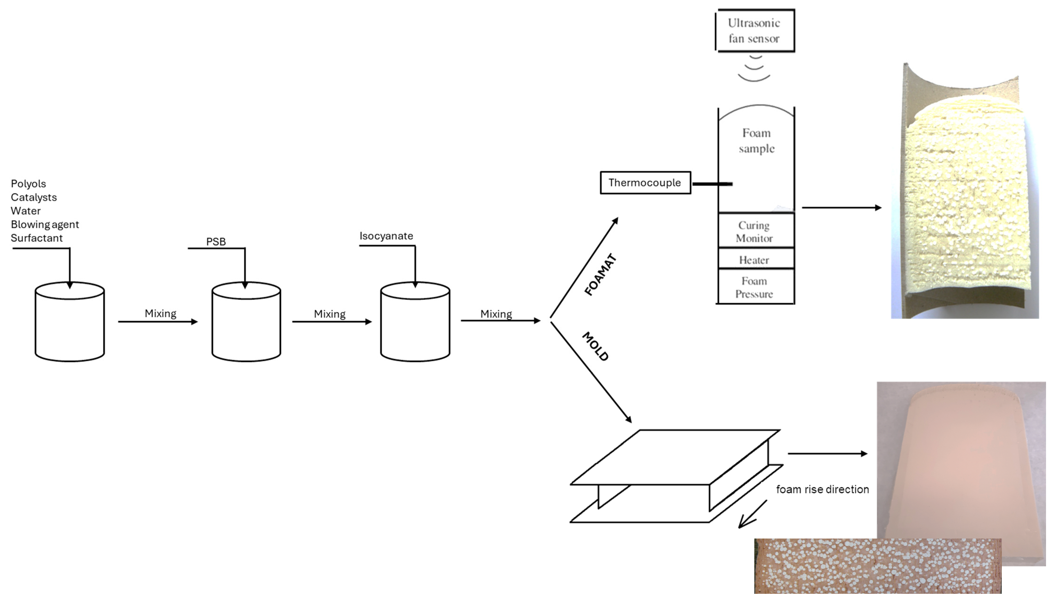
All of the RPURFs and RPURF-EPSs were synthesized with a one-shot method at room temperature. The formulation used for composite preparation differed by the type of blowing agent and addition of PSB. The reference foams contained 0 wt.% of PSB beads and RPURF-EPS composites contained: 35 wt.% of the PSB relative to the weight of polyurethane. These proportions resulted from previous experiments. Polyol, catalyst, surfactant and blowing agent were weighed into a PP cup and mixed with an appropriated amount of the PSB beads. Then, an appropriate component B was added to the mixture and vigorously stirred at 1200 rpm for 10 s. After mixing, the mixture was poured into an open mold. Mold was made of plastic coated with a silicone paper. Scheme of composites obtained is shown in
Figure 1. The mold had dimensions of 300 × 300 × 50 mm
3 and was limited on three sides and closed at the top. The increase in the mixture occurred in a horizontal direction. The foam was cured in the mold for two hours at room temperature before being removed and cut into appropriate specimen for testing.
The amount of components required to prepare a polyurethane system were selected so as to obtain a foam having a density of approx. 40 kg/m
3. The isocyanate index in all compositions was 1. In the case of composites, PSBs were added in an amount of 35 wt%. in relation to the polyurethane components. The formulation of polyurethane systems from which the RPURF and RPURF-EPS were obtained are shown in
Table 1.
In order to determine the influence of the blowing agent type on the foaming process and properties of the RPURF and RPURF-EPS, the following analyses were carried out.
Analysis of foaming process parameters was conducted using a FOAMAT® device (manufactured by Format Messtechnik GmbH, Karlsruhe, Germany). FOAMAT device measures the characteristic parameters of the foaming process, such as the height of foam growth, the reaction temperature, the pressure and the dielectric polarization. The data obtained allow for the calculation of the material rise velocity, its shrinkage, start, rise and gelling time.
Analysis of material structure included determining the following parameters: the volume of the EPS phase in the RPURF-EPS and the diameter of EPS as well as cell structure analysis of the RPURF were carried out with Aphelion program, and content of the closed cells in the RPURF and RPURF-EPS was determined according to the ISO 4590 standard [
28].
The core apparent density of the RPURF-EPS composites was determined according to the ISO 845 standard [
29] using cubical samples of 50 mm side by side measurement of their volume and mass.
Mechanical properties were measured on a Zwick 1445 (Zwick Roell Group, Ulm, Germany) universal testing machine at room temperature. The measurement of compressive strength of the RPURF and RPURF-EPS composites was performed according to the ISO 844 standard [
30]. The force required for 10% deformation of the original thickness of composites was taken as compression strength of the foams. The speed of crosshead movement was 5 mm/min. Tests were performed at horizontal and vertical directions to the foam rise.
Thermal conductivity of materials was measured using the FOX 200 (TA Instruments, New Castle, DE, USA) apparatus according to the PN-EN 12667 standard [
31]. Samples for thermal conductivity analysis were prepared from the received slab by cutting it to a size of 20 × 20 cm. After demolding, the sample was 5 cm thick, so no cutting of the thickness was necessary.
3. Results
3.1. Analysis of the Foaming Process
The foaming process analysis was carried out using FOAMAT. This device monitors changes in core temperature, pressure, foam height and dielectric polarization in time.
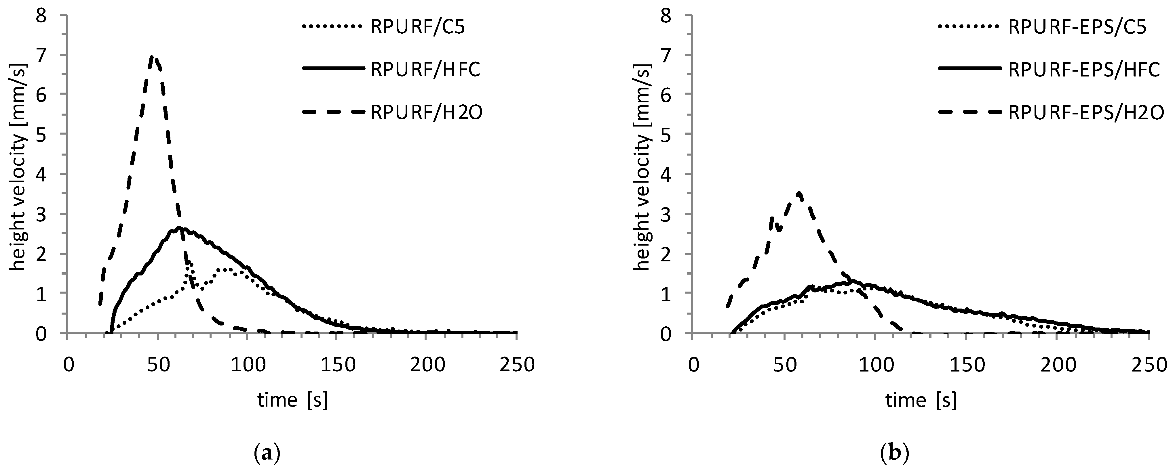
The rise velocity changes of RPURF and RPURF-EPS are shown in
Figure 2. It was found that regardless of the blowing agent type, RPURF grows faster than RPURF-EPS. The highest rise velocity was observed for water-blown materials. This rise velocity was about 7 mm/s for the reference foam and 4 mm/s for the composite. The rise velocity of HFC-blown materials is slightly faster in relation to the cyclopentane-blown materials. This is due to the fact that the HFC starts to evaporate at a lower temperature than cyclopentane. In addition, the HFC reduces the viscosity of the mixture more than cyclopentane, and it promotes the rapid growth of the foam.
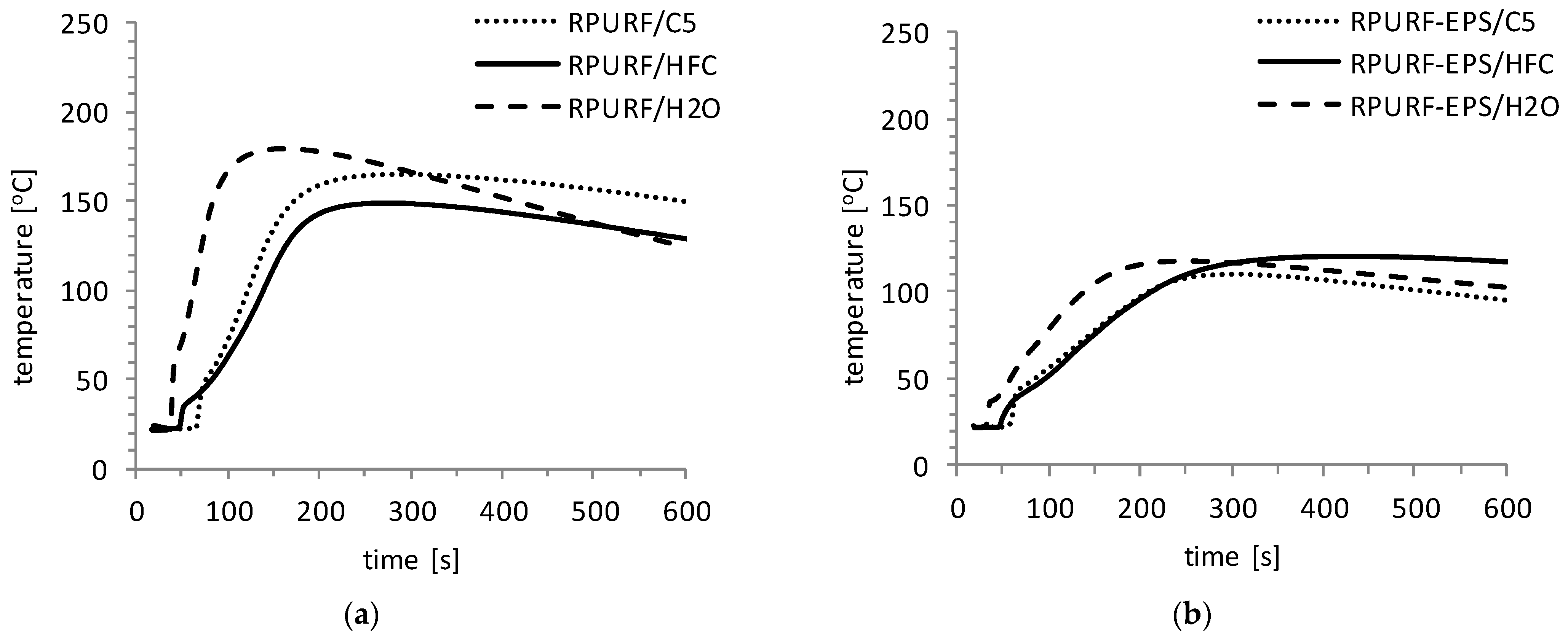
The foam core temperature changes in time are presented in
Figure 3 separately for RPURF and RPURF-EPS. The reference foam core temperature is higher compared to the composite. This is due to the fact that the heat of the PUR-forming reaction is consumed by the endothermic process of PSBs expanding. The synthesis of RPURF and RPURF-EPS blown with water was characterized by the highest temperatures. The maximum core temperature for water-blown RPURF was about 180 °C, and for the RPURF-EPS, it was about 127 °C. The temperature increases in the water-blown materials is the fastest because the reaction of water with isocyanate takes place from the moment of mixing the raw materials. Additionally, that reaction is exothermic and generates extra heat in the system.
The maximum core temperature of cyclopentane-blown RPURF was 163 °C and cyclopentane-blown RPURF-EPS was 122 °C. While the maximum core temperature of HFC-blown RPURF and RPURF-EPS were lower compared to the cyclopentane-blown materials and were respectively 137 °C and 115 °C. In the case of materials blown with cyclopentane the temperature rise was more rapid in comparison to the materials blown using fluorocarbons. Cyclopentane starts to evaporate when the mixture obtains a temperature of 50 °C. In contrast, the hydrofluorocarbon blowing agent has a lower boiling point temperature (about 30 °C) with respect to cyclopentane. Therefore, part of the heat of the PUR-forming reaction is consumed to evaporate HFCs from the very beginning of the foaming process. This affects the decrease of temperature in the core of HFC-blown material.
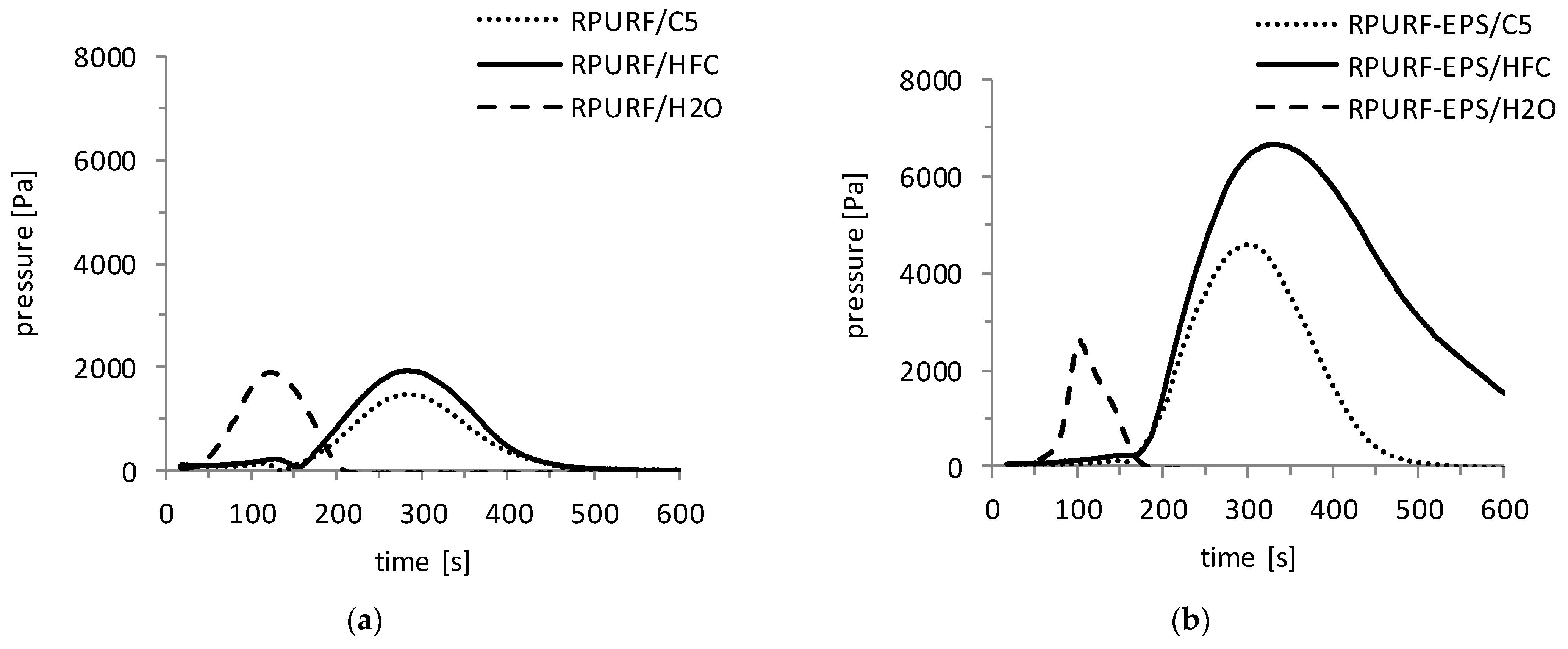
It was observed that the pressure exerted on the bottom of the device during the composite foaming process is higher compared to the reference foam (
Figure 4). As in the case of temperature, the pressure increase takes place most rapidly in water-blown materials. The pressure increases in the material blown with physical blowing agents are delayed relative to water-blown materials, which is due to the longer start time and slower growth of PUR. The highest maximum pressures were observed for the RPURF and RPURF-EPS blown with cyclopentane. Water-blown RPURF-EPS was characterized by the lowest maximum pressure value. This may be due to the high content of open cells in this composite.
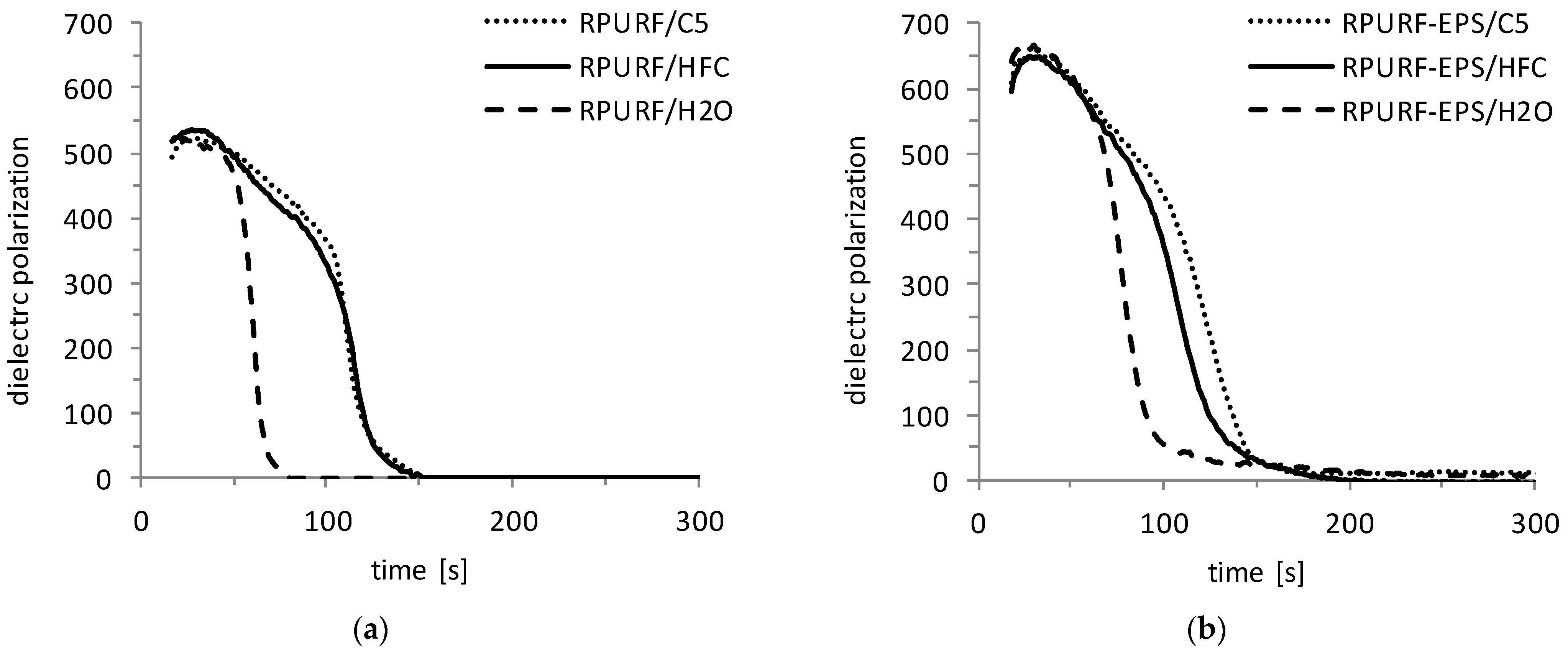
The raw materials for the synthesis of PUR contain polar, free hydroxyl and isocyanate groups in their molecules. That affects the high dielectric polarization value of the reaction mixture at the start of the measurement. As a result of the polymer chain growth and crosslinking process, the mobility of these groups is limited. Therefore, the reduction of dielectric polarization value occurs during polyurethane formation [
32]. At the time of the full cure, the dielectric polarization value reaches zero. Therefore, the value of the dielectric polarization can determine the degree of the conversion of the substrates during the PUR-forming reaction.
Changes in the dielectric polarization in time for RPURF and RPURF-EPS are shown in
Figure 5. RPURF and RPURF-EPS blown with water are characterized by the fastest dielectric polarization decrease. This is because the formation and crosslinking reactions in these materials occur with the highest speed. The value of the dielectric polarization approaches zero after approx. 80 s for RPURF/H
2O and after approx. 120 s for RPURF-EPS/H
2O.
Considering the materials blown with physical blowing agents, dielectric polarization changes were very similar regardless of whether HFCs or cyclopentane was used. The dielectric polarization approaches zero for cyclopentane- and HFC-blown RPURF after approx. 150 s, whereas for cyclopentane- and HFC-blown RPURF-EPS after approx. 180 s. The slower dielectric polarization decrease in RPURF-EPS is due to the presence of PSBs that slow down forming and crosslinking reactions. This is confirmed by measurements of the rise velocity and temperature changes in RPURF and RPURF-EPS.
Start, rise and gelation times for RPURF and RPURF-EPS are presented in
Table 2. The value of the start times of RPURF and RPURF-EPS foamed with the same blowing agents are similar. The shortest start times have water-blown materials, which, for the RPURF and RPURF-EPS, is 18 s. The cyclopentane-foamed materials have the longest start time (approx. 32 s). The HFC-blown materials have a shorter start time compared to compositions containing cyclopentane. This is due to the lower boiling point of the HFC, which starts to evaporate at the very beginning of the foaming process. Rise and gelation times for composites are longer in comparison to the reference foams. The addition of PSBs prolongs the time of the creation and crosslinking of PUR, which was confirmed, for example, by measuring dielectric polarization changes.
3.2. Analysis of the Material Structure
Volume share and diameter of EPS in RPURF-EPS
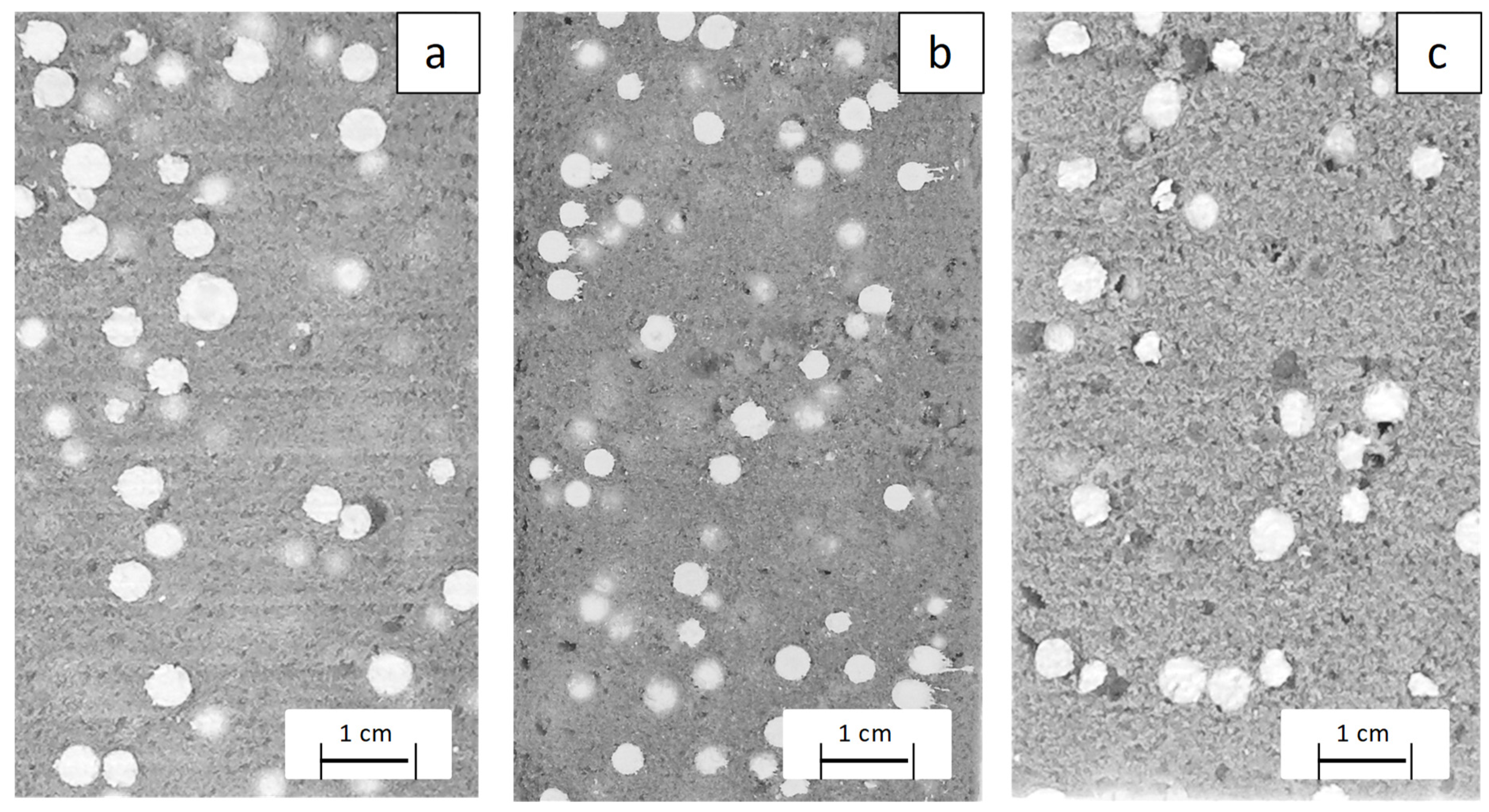
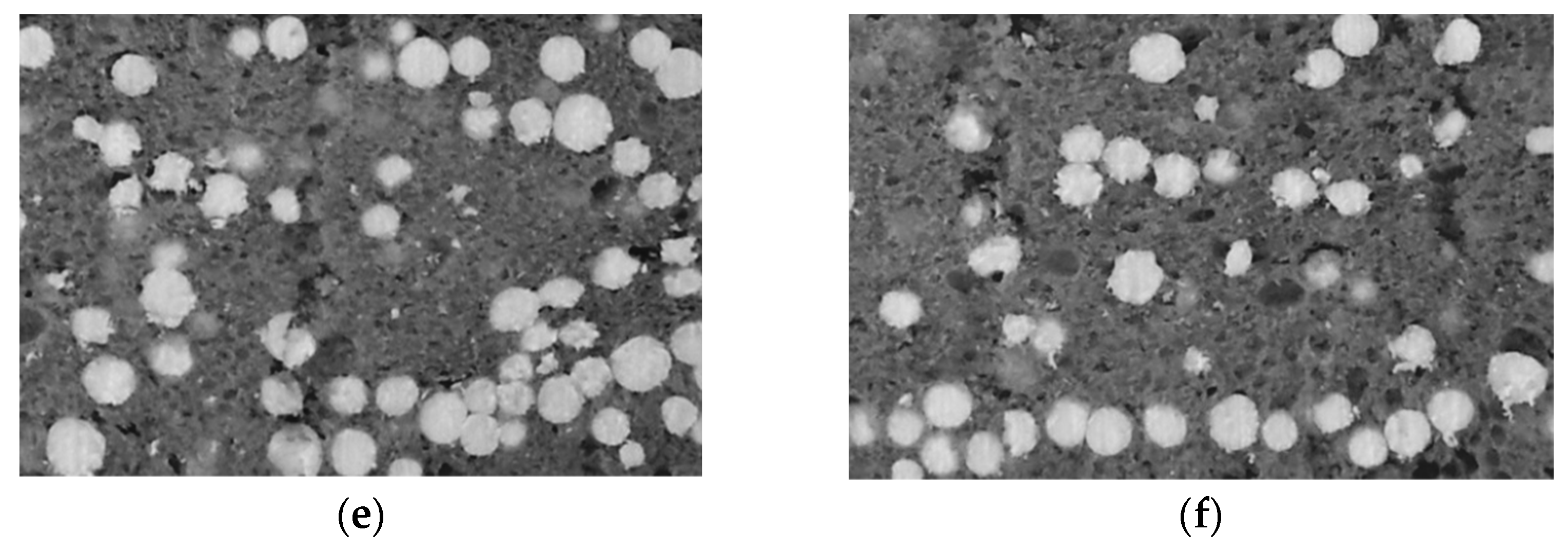
The analysis of the volume fraction of EPS beads and the diameters of their cross-sections was made using an analysis of composite section images. Examples of RPURF-EPS section images are presented in
Figure 6.
In the case of water-blown RPURF-EPS, the core temperature was so high that it resulted in the melting of the EPS beads inside. Therefore, it was decided to reduce the core temperature of that composite by increasing the amount of added PSBs.
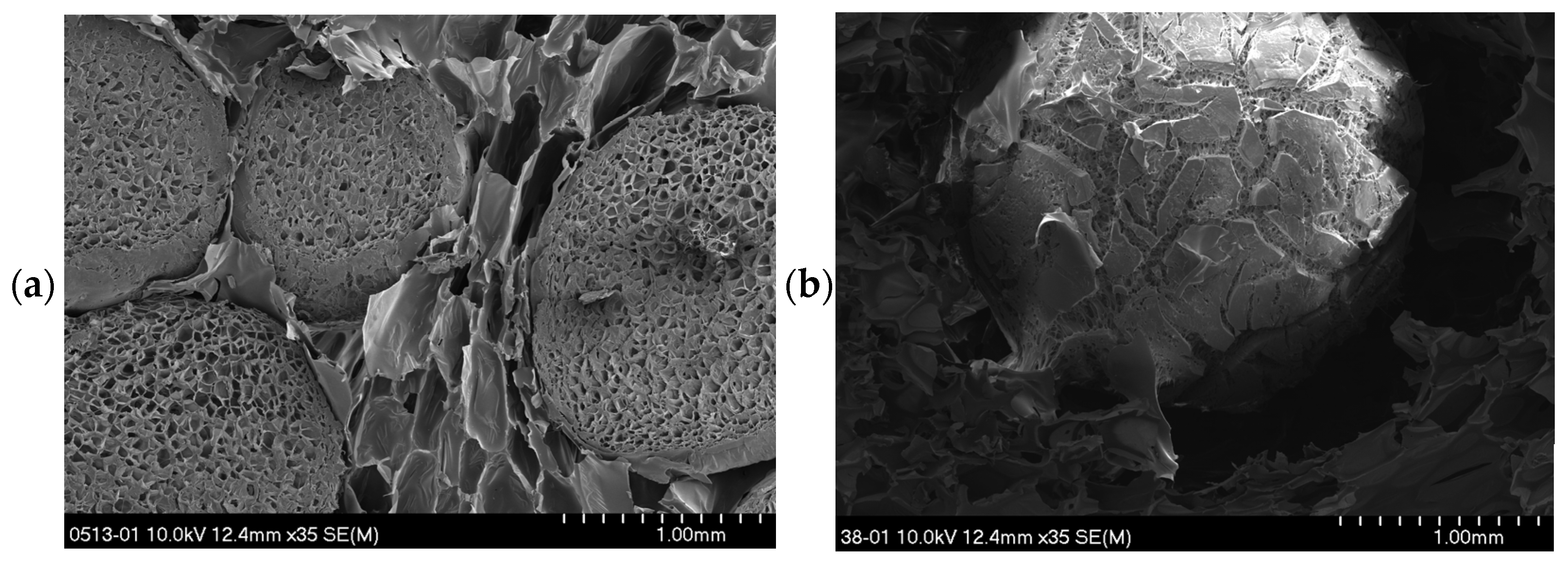
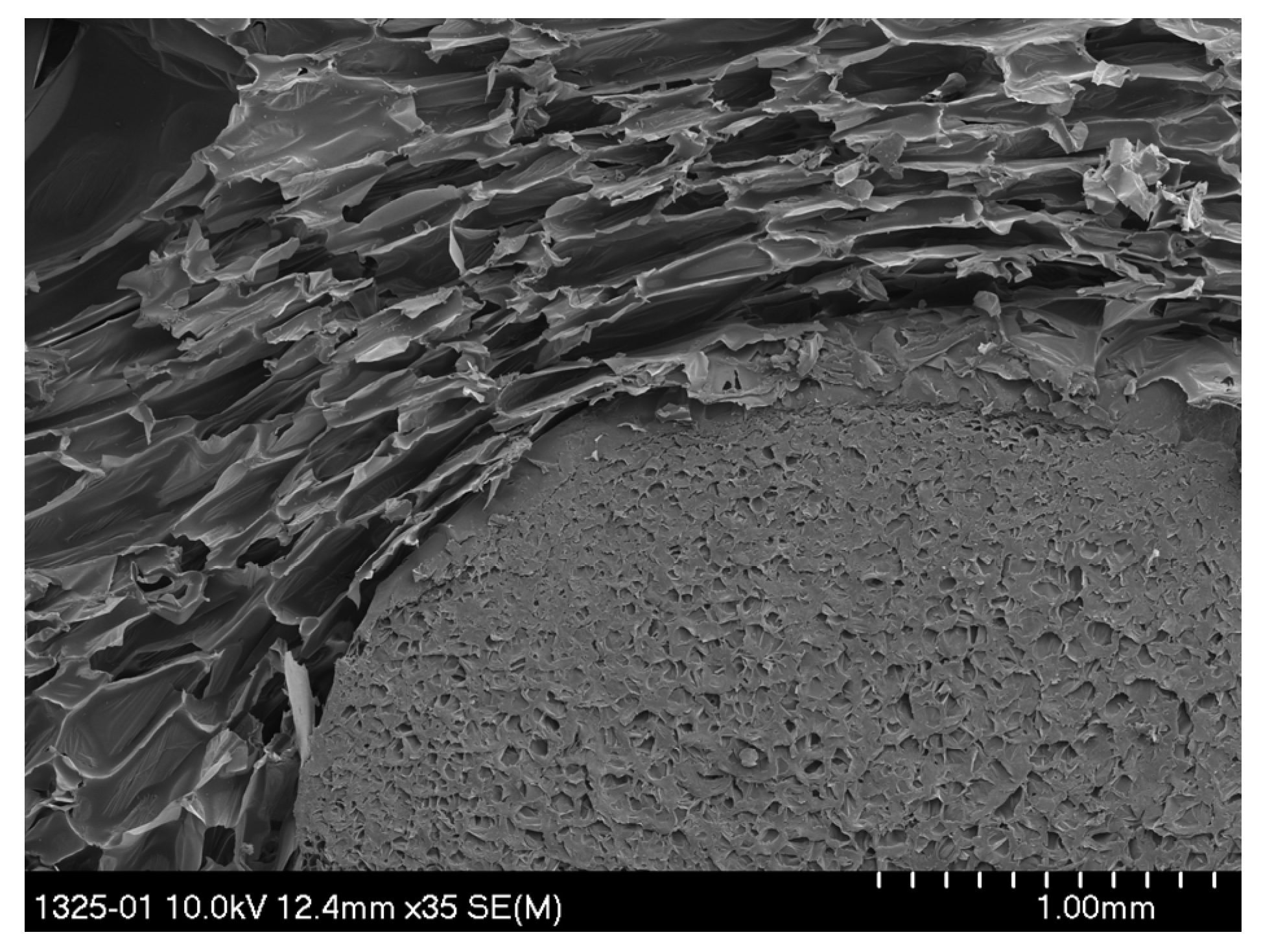
Figure 7 shows SEM images of EPS beads in the composite.
Figure 7a shows beads that have been properly expanded, while
Figure 7b shows an EPS bead that has over-melted.
The results of the EPS volume fraction analysis and mean value EPS of cross-sections diameters for composites foamed with different blowing agent were presented in
Table 3. We also compared how the volume fraction and EPS diameter changed depending on the increasing amount of PSBs in water-blown composites.
In the case of RPURF-EPS blown with physical blowing agents, the size and the volume share of EPS beads are similar. The volume fraction of EPS in the composite foamed with cyclopentane is 12%, and in the HFC-blown composite, it is 10%. The lowest volume fraction and the smallest average diameter of EPS have RPURF-EPS foamed with water. This is due to EPS melting during the co-expansion process, which is caused by too high temperature in the composite core.
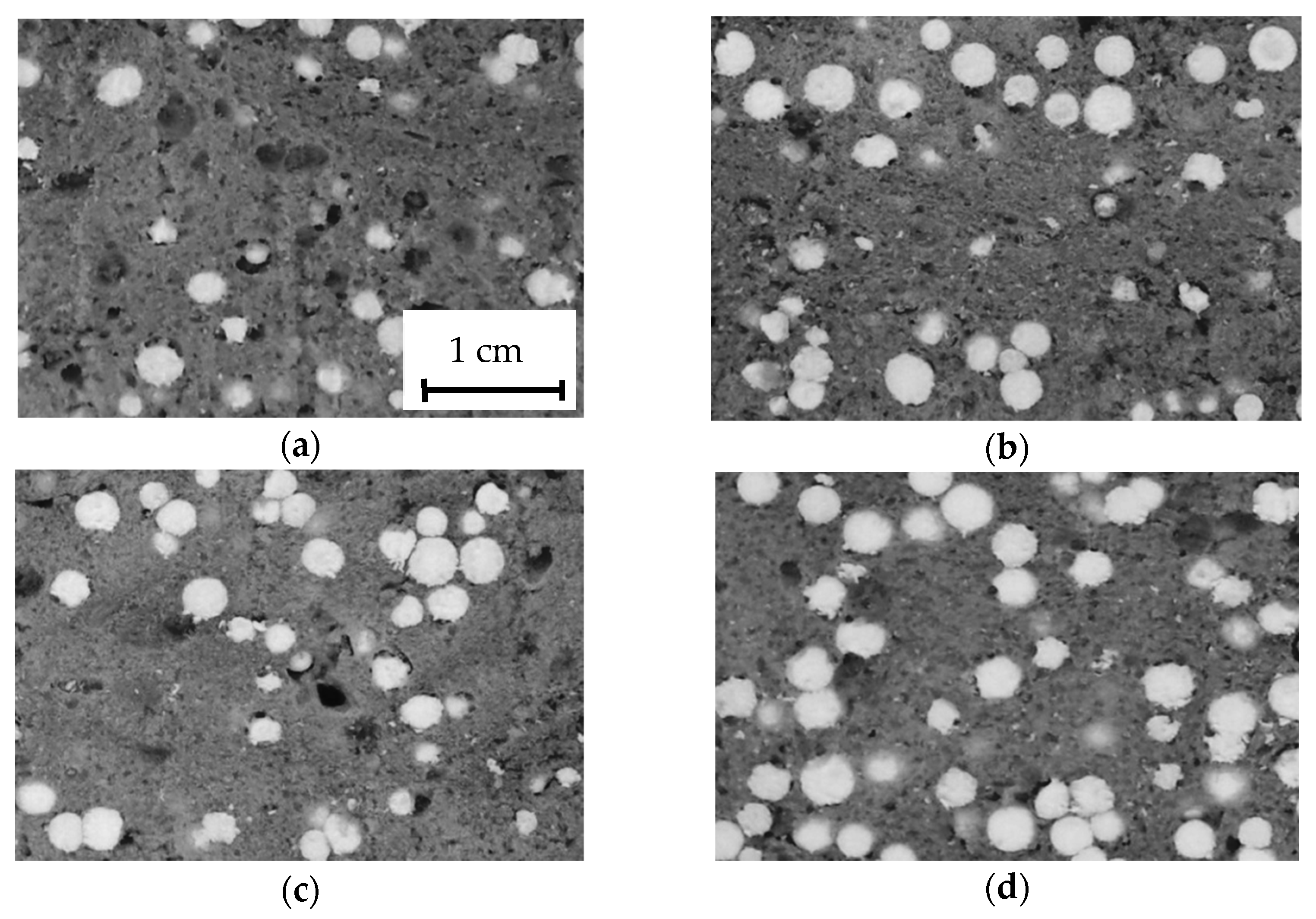
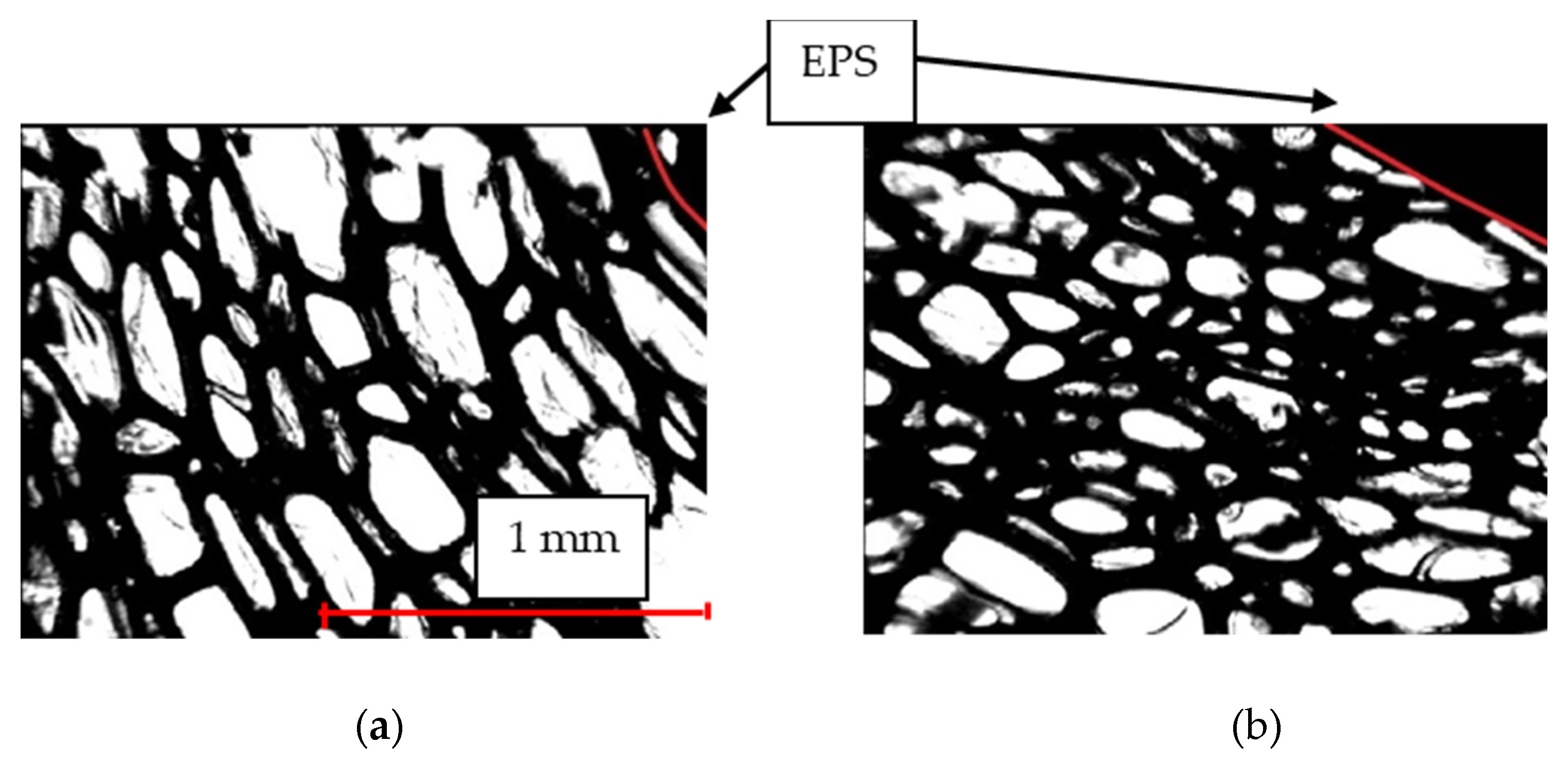
Cross-sections of water-blown RPURF-EPS are presented in
Figure 8. It was observed that the addition of 35% PSBs to the composite caused the beads to melt in the inside of the material. To reduce the temperature in the composite core, which was 126 °C, the amount of PSBs was increased. The more PSBs that were added to the reaction mixture, the greater the amount of heat was necessary for its expansion. This resulted in a decrease in the temperature inside the material.
It was found that the increasing mass fraction of the PSBs increases the volume fraction of the polystyrene-phase water-blown RPURF-EPS. Increasing the amount of PSBs caused the increase in the EPS bead diameters only up to the point, where the larger addition of PSBs no longer causes the increase in the diameter of EPS. The further addition of PSBs causes such a large decrease in the temperature within the composite that this reduces the degree of expansion. In the case of water-blown RPURF-EPS, it was found that the addition of 50% mass PSBs provides the best expansion degree of EPS.
Conducting the analysis of the polyurethane-phase cellular structure, it was found that EPS beads have a great influence on it. Cells that are located near the beads have a different shape and size from those in the distance from the EPS.
Figure 9 shows an SEM image of the polyurethane foam cells near the EPS. The image shows that the polyurethane foam cells align along the EPS bead and are flattened by its growth.
Therefore, the analysis of the cellular structure of SPPUR-EPS was carried out in two zones—in the area 2 mm away from the EPS beads (zone I) and in the zone close to the EPS (zone II). It was assumed that if the EPS is in the very corner of the microscope magnification image, the remaining area is covered by polyurethane foam approximately 2 mm wide (
Figure 10). For each of the samples, the average width and height of cells, the average number of cells, the average cell surface and the average anisotropy index were determined.
The results of the cellular structure analysis of RPURF and RPURF-EPS in zone I are presented in
Table 4. RPURF and RPURF-EPS are characterized by higher values of the average anisotropy index on the cross-section that is parallel to the direction of growth than on the perpendicular cross-section [
32]. This is because cells during the foaming process are extended in the direction of the foam rise. In contrast, cells on the perpendicular cross-section are smaller, their shape is more like a circle and the anisotropy factor is close to 1. The largest value of the anisotropy index on both cross-sections (parallel and perpendicular to the foam rise) was observed for water-blown RPURF and RPURF-EPS. These materials are characterized by the smallest size and surface of cells and the largest number of cells on 1 mm
2. Cells in water-blown materials were also the most elongated in the direction of growth, which is reflected in the highest values of the anisotropy index. This is the result of the fastest growing water-blown RPURF and RPURF-EPS.
It was observed that the cellular structure of RPURF-EPS in zone I was characterized by higher values of the anisotropy index in the perpendicular direction and smaller values of the anisotropy index in the parallel direction to the direction of the foam rise in comparison to RPURF. The presence of EPS in composites limited the elongation of the cells in the rise direction, while causing their extension in a perpendicular direction to the foam growth direction.
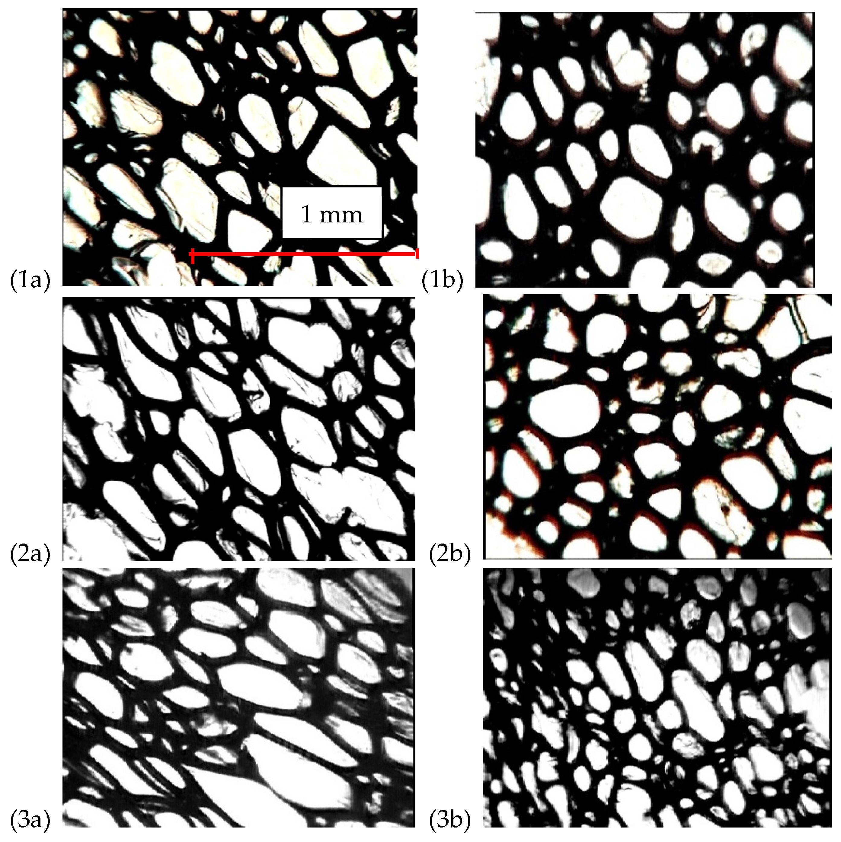
Exemplary cellular structures in zone I of RPURF-EPS foamed using different blowing agents in perpendicular and parallel cross-sections to the growth direction are shown in
Figure 11.
The results of the analysis of the cellular structure in zone II are shown in
Table 5. In zone II, the PUR cellular structure is irregular, and the cells are deformed due to the presence of EPS. The anisotropy indexes of cells near EPS differ significantly from those in zone I. The anisotropy indexes of cells on parallel cross-section to the direction of the foam rise for composites blown with water and HFCs are smaller in relation to the values of the indexes in zone I, whereas for cyclopentane-blown composites, the anisotropy index is greater near EPS than in zone I.
The cell structure in zone II of RPURF-EPS blown with HFCs are shown on
Figure 11. It was observed that the cells in the parallel cross-section to the growth direction are arranged irregularly and become flattened near EPS. On the perpendicular cross-section, PUR cells near the EPS are smaller and have a small average cell area.
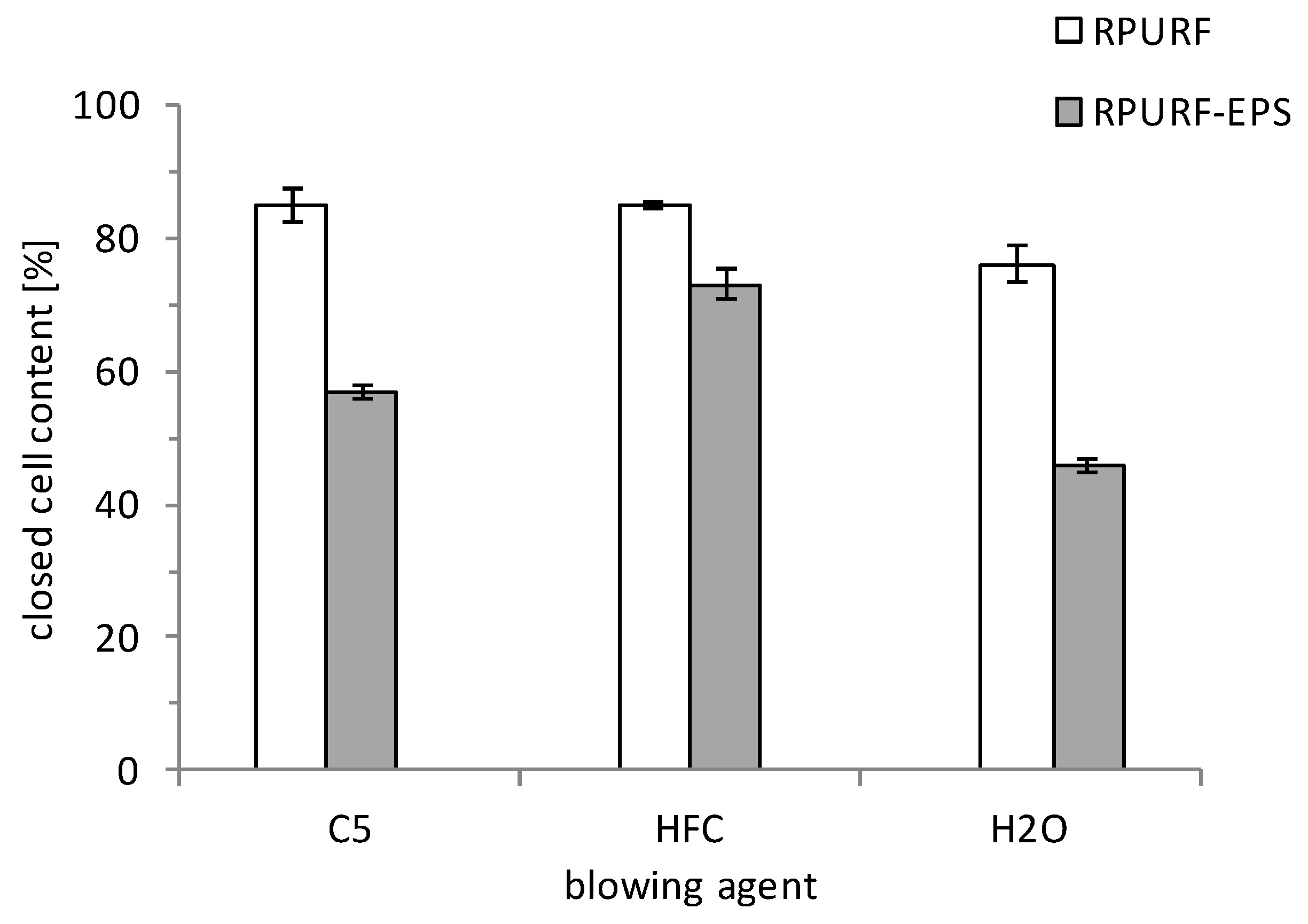
3.3. Closed Cell Content
A comparison of closed cell content in RPURF and RPURF-EPS is presented in
Figure 12. The reference foam foamed with physical blowing agents is characterized by similar closed cell content. The closed cell content in RPURF blown with cyclopentane and HFCs is, respectively, 83% and 86%. In contrast, the content of closed cells in RPURF blown with water is much lower (76%). The rapid process of the expansion and growth of water-blown RPURF and RPURF-EPS caused the cells’ opening, which resulted in a small closed cell content.
Composite materials have a lower content of closed cells compared to RPURF. The reason for this is the presence of EPS, which disrupt the structure of the polyurethane by introducing discontinuities in the polyurethane matrix or by the melting of the beads. RPURF-EPS foamed with HFCs have the highest content of closed cells at the level of 73% of all the composites. Similar closed cell content in the HFC-blown reference foam and the composite indicates the smallest effect of the PSB addition on PUR structure in RPURF-EPS/HFC. A higher closed cell content in RPURF and RPURF-EPS blown with physical blowing agents is due to a slower growth of these materials.
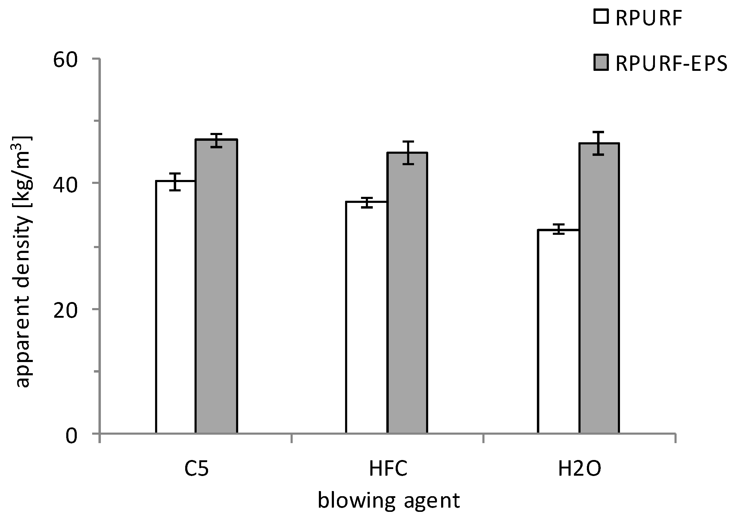
3.4. Physical–Mechanical Property Analysis
The physical and mechanical properties of RPURF and RPURF-EPS containing 35% by mass of PSBs were analyzed.
The apparent density of the received foam materials is presented in
Figure 13. RPURF and RPURF-EPS foamed using cyclopentane were characterized by the value of greatest apparent density. Cyclopentane evaporation starts at a higher temperature than HFC evaporation when PUR could already be under partial gelation. This reduces the formation of new bubbles and results in the higher apparent density of the material.
The addition of PSBs influenced the apparent density. RPURF-EPS were characterized by the higher value of apparent density in relation to RPURF, mainly because the viscosity of polyol premix with PSBs increased [
33,
34,
35]. RPURF-EPS foamed with different types of blowing agents were characterized by similar apparent density. Water-blown RPURF had the lowest apparent density. In the case of RPURF-EPS, the lowest apparent density had the material foamed using HFC.
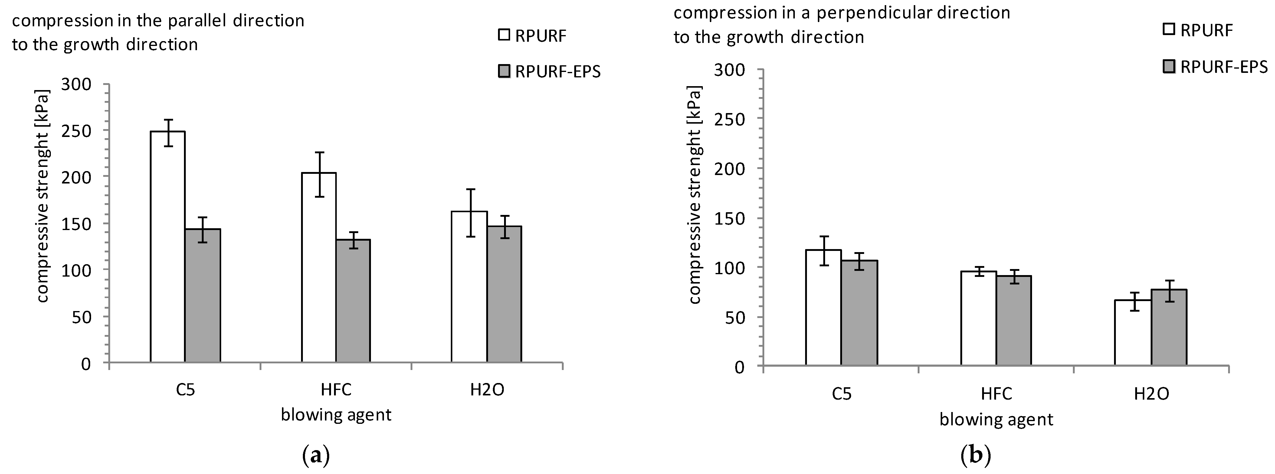
The apparent density of the material affects other properties, such as compressive strength. Because RPURF and RPURF-EPS have an anisotropic structure (foam cells are elongated in the direction of its growth), the study was carried out in two directions: parallel and perpendicular to the growth direction of the foam.
Figure 14 shows the compressive strength of the reference foam and composites depending on the type of blowing agent.
The compressive strength of all materials tested in a direction parallel to the foam rise direction is greater than the strength measured in the perpendicular direction. RPURF-EPS have a lower compressive strength in the parallel direction than RPURF.
The decrease in the strength of the material is due to the presence of EPS beads that disturb the structure of PUR. In contrast, the addition of EPS does not affect the compressive strength in the perpendicular direction. The smallest impact of EPS beads on compressive strength was observed for RPURF-EPS foamed with water. The materials foamed with cyclopentane were characterized by the greatest compressive strength. The type of blowing agent and the apparent density have an influence on the strength of the tested materials.
RPURF and RPURF-EPS foamed with cyclopentane are characterized by the highest compressive strength and the highest apparent density. The use of cyclopentane results in a lower plasticization of the PUR matrix compared to HFC, which also affects the superior mechanical strength of cyclopentane-foamed materials. It was found that RPURF-EPS foamed with water have a higher compressive strength in the direction parallel than RPURF-EPS foamed with HFCs and cyclopentane. Water-blown materials have a higher anisotropy of cells in a parallel section than RPURF-EPS foamed with HFCs and cyclopentane, which could have an influence on improving the compressive strength in the parallel direction.
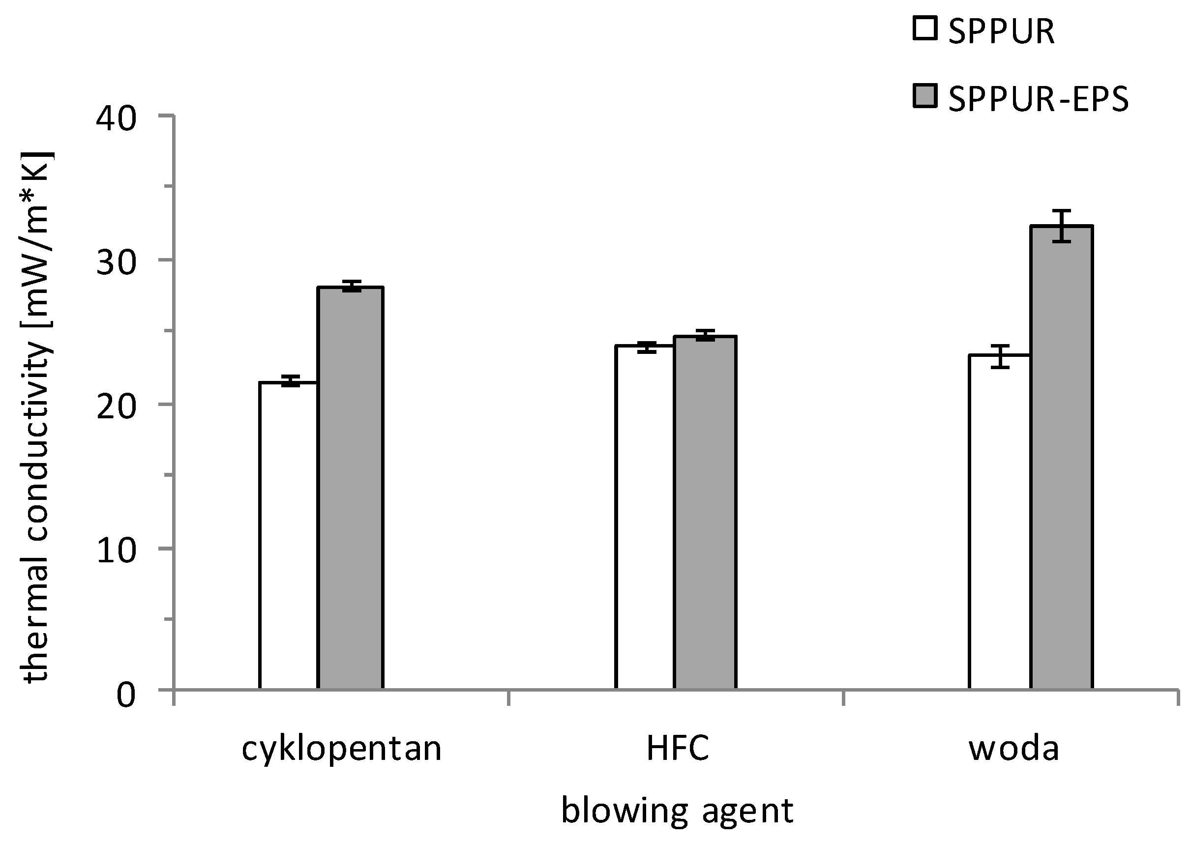
3.5. Thermal Conductivity of RPURF and RPURF-EPS
The insulating properties of foamed materials depend largely on the type of gas closed in the cells, which occupies almost the whole volume of materials with low apparent density. The thermal conductivity of gas is reduced with increasing molecular weight and is highest for carbon dioxide and lowest for HFCs. The mechanism of heat transfer through the porous materials is complicated. Therefore, it is also necessary to take into account the effect of other parameters on thermal conductivity, such as the size and anisotropy of cells, closed cell content and bulk density of the material [
35,
36].
Measurements of thermal conductivity for all materials were carried out after 24 h, and the results are shown in
Figure 15.
Reference foams have a lower thermal conductivity relative to RPURF-EPS. This is due to the higher value of the thermal conductivity of polystyrene. Water-blown RPURF and RPURF-EPS have the worst heat-insulating properties due to the presence of carbon dioxide in the cells. Carbon dioxide is characterized by the highest thermal conductivity and the fastest diffusion through the cell walls between blowing agents used. Theoretically, materials foamed with HFCs, which have the smallest thermal conductivity, should have the best thermal insulation properties. Among RPURFs, the lowest thermal conductivity (21.5 mW/m∙K) showed the material foamed with cyclopentane, while the value of thermal conductivity for HFC-blown RPURF was 23.9 mW/m∙K, and for water-blown RPURF, it was 23.4 mW/m∙K. This phenomenon can be explained by the influence of heat transport by radiation and the PUR matrix on value of thermal conductivity. The cell anisotropy index can affect the heat transport. Larger cell elongation in the direction perpendicular to the heat flow direction reduces the number of thermal bridges, the presence of which reduces the heat-insulating foam properties. Elongated cells form more layers on a cross-section parallel to the direction of heat flow, and the wall constitutes a barrier of radiation. It follows that increasing the coefficient of the anisotropy of the cell in the direction perpendicular to the direction of heat flow results in the improved thermal insulation properties of the material. Therefore, cyclopentane-foamed RPURF may be characterized by the lowest thermal conductivity.
For RPURF-EPS, it was observed that the increasing apparent density of the material also increases the thermal conductivity. The best thermal insulation properties and the lowest apparent density have composites foamed with HFCs. The value of the thermal conductivity of these materials is 24.65 mW/m∙K.
Another parameter that influences the thermal insulation properties of foam materials is a closed cell content. Porous materials with good thermal insulation should contain a large number of closed cells. It is assumed that the higher the content of closed cells in the material is, the smaller the thermal conductivity is.
There was no clear correlation between the content of closed cells and the value of thermal conductivity in reference RPURFs. In the case of RPURF-EPS, a reduction in the thermal conductivity with an increasing content of closed cells was observed. The largest closed cell content and the lowest thermal conductivity characterized RPURF-EPS foamed with HFCs.
Water-blown composites contain only 46% of closed cells, which affects the greatest value of thermal conductivity. Similar values of thermal conductivity of RPURF and RPURF-EPS blown with HFCs result from similar closed cell content, which for the reference foam is 86%, and 75% for the composite. It was found that the greater difference in the contents of cells closed between RPURF and RPURF-EPS, the greater the difference in the values of thermal conductivity will be. The greatest difference in the content of closed cells and the value of thermal conductivity was characterized by water-blown RPURF and RPURF-EPS. Closed cell content was, respectively, 76% for RPURF and 46% for RPURF-EPS. Thermal conductivity values were 23.9 mW/m∙K for RPURF and 31.7 mW/m∙K for RPURF-EPS.
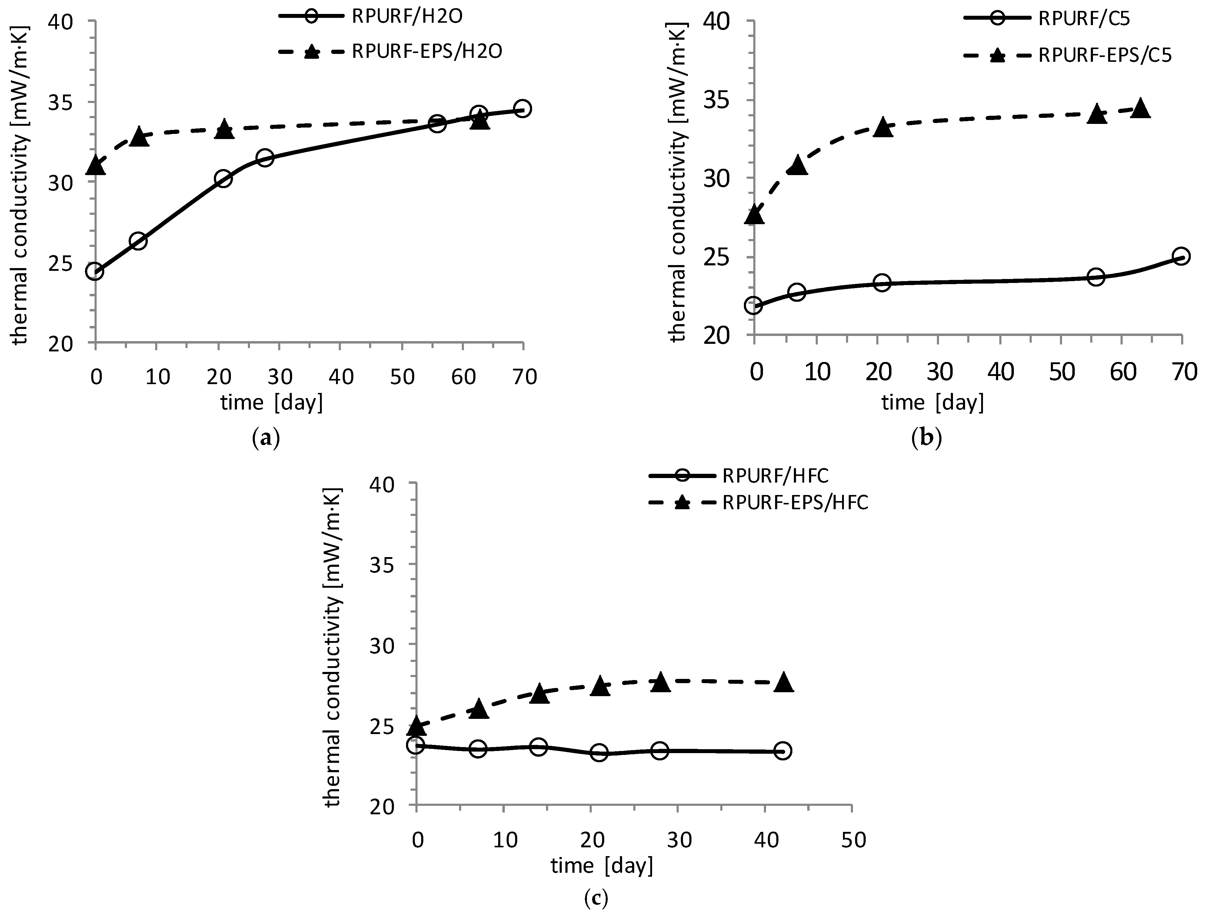
The insulating properties of foam materials deteriorate with time. Therefore, the measurement of the thermal conductivity of the reference and composite foams were repeated at weekly intervals for a certain period. Obtained material in the process of aging showed an increase in thermal conductivity over time. The reason for this is mainly in the diffusion of air into the foam cells and volatilization of physical blowing agents.
Carbon dioxide has the quickest diffusion through the cell walls. Therefore, the rapid increase in the thermal conductivity of the water-blown materials at the time occurs (
Figure 16a). Physical blowing agents more slowly diffuse through the cell walls into the atmosphere. Therefore, an increase in the value of thermal conductivity in materials blown with physical blowing agents is slower (
Figure 16b,c).


