Abstract
This paper is the first part of a two-part paper that discusses the development of a novel lightweight and cost-effective hybrid 3D composite material and its and utilization for constructing utility poles. The main objective was to generate a material/pole with a comparable performance to the commercially available poles made of 2D fiber-reinforced polymer (FRP) and examine its feasibility. The novel hybrid composite was configured using a recently developed and marketed 3D E-glass fabric–epoxy composite reinforced with wood dowels, referred to as 3D dowel-reinforced FRPs (3D-drFRPs) hereafter. Firstly, the compressive and flexural properties of the 3D-drFRPs are evaluated. Then, the development of the 3D pole is discussed followed by the fabrication details of two 3D-drFRPs using the standard test method, and their responses are compared. For the second part, robust finite element (FE) models were developed in an LS-DYNA environment and calibrated based on the experimental results. A sophisticated nonlinear FE model was used to simulate the performances of ASTM standard-size compression and three-point bending specimens and tapered 2D and prismatic 3D poles. Moreover, the responses of equivalent 2D and 3D poles were simulated numerically, as the task could not be accommodated experimentally due to our laboratory’s deficiencies. The integrity of the numerical simulation results was validated against experimental results, confirming the accuracy of the developed model. As an example, the stiffness values for the 3-pt bending specimens and the 3D poles obtained through the simulations were very close to the experimentally obtained results, with small margins of errors of 3.2% and 0.89%, respectively. Finally, a simplified analytical calculation method was developed so practicing engineers can determine the stiffnesses of 3D-DrFRP poles very accurately and quickly.
1. Introduction
1.1. Brief Historical Overview
In 1844, Washington, D.C., saw the first recorded use of wooden utility poles for telegraph transmission [1]. Presently, the United States has an estimated 160–180 million wooden utility poles, primarily made from southern pine, Douglas fir, and western redcedar [2]. Wood, being cost-effective and renewable, aids in carbon dioxide absorption. While concrete and steel are also employed for utility poles, concrete is heavy and costly, while steel is lighter and fully recyclable [3]. However, steel poles are susceptible to corrosion and are often pricier than wood alternatives [3].
Glass fiber-reinforced polymers (GFRPs), widely used in various industries, are chosen for FRP utility poles due to their cost-effectiveness compared to other FRP types [4]. GFRPs’ initial application dates back to the early 1940s in marine boats [5]. Approximately twenty years later, the first GFRP utility pole was installed in Hawaii, serving for around 50 years before UV exposure led to its removal [3].
The development of FRP poles in the US can be guided by standards like ACMA/UCSC UP01-18-2019 from the American National Standards Institute [6] or Engineering Practice No.104 from the American Society of Civil Engineers [6,7]. Given the lower popularity of concrete and steel poles compared to wood in North America, the discussion in the subsequent subsections of this section focuses on wood and FRP poles.
1.2. Advantages of FRP Poles
Wood utility poles installed in regions with severe weather conditions are highly susceptible to decay, with over half of the poles removed in the Pacific Northwest attributed to decay [8]. Factors contributing to wood pole decay include ultraviolet light, insects, and decay fungi, particularly in humid environments [8]. Decay is accelerated in regions with high humidity and frequent rainfall, making wood poles vulnerable, thus requiring special treatments of the poles [9].
In contrast, FRP poles are inherently resistant to material decay. UV and fire inhibitors have extended the service life of treated GFRP poles to over 80 years [3], while wood poles typically last between 40 and 56.8 years [10]. Wood poles require maintenance every decade, whereas FRP poles demand minimal upkeep, with some manufacturers, like R.S. Technologies Inc., Tilbury, ON, Canada, asserting a maintenance-free 120-year life cycle [11].
Despite these advantages, there is no standard governing the design of FRP poles. Manufacturers have flexibility in adjusting pole dimensions to match specific loading criteria for wood pole classes [7]. Notably, due to GFRPs’ high specific strength, a class 1 wood pole is approximately three times heavier than an equivalent GFRP pole, as reported by R.S. Technologies Inc. [11].
The modern GFRP pole design is modular, offering several advantages over traditional wood and monolithic GFRP poles. Modular poles are easier to transport, as modules can be nested for efficient transportation. Different module sizes can be combined to create poles of various lengths and rigidities to suit different applications, such as power transmission and distribution. Additionally, in the event of a catastrophic failure, only the failed modules need replacement, eliminating the need to replace the entire pole. Moreover, it should be noted that while the overall cost of a composite pole is higher than a pole made of traditional materials, the low cost of transportation, faster installation, minimal required maintenance, and the overall life cycle of composite poles outweigh their initial cost.
While the current commercially available 2D poles are lightweight, resilient, and modular, their specific stiffness (i.e., stiffness-to-weight ratio) can be improved cost effectively. This factor is crucial when considering the vibration and buckling capacity of such poles. Notwithstanding, the Achilles heel of most FRPs is the delamination phenomenon, due to the relatively much weaker resin constituent and the mismatch in mechanical properties exacerbated due to stacking sequences. FRPs are quite susceptible to delamination under compressive and bending loads. The inherent nature of the 3D woven fabric significantly decreases the likelihood of delamination compared to its 2D layered counterpart. The woven pillar-to-fabric connection significantly enhances the overall stiffness and interlaminar strength, rendering a 3D glass–epoxy panel with a significantly stronger bending stiffness than its equivalent 2D counterpart. Nonetheless, the response of the material subjected to the aforementioned loading states should be examined, especially for the existence of any voids and deformations induced on the empty channels of the fabric due to the consolidation process (i.e., the application of shrink wrap) can potentially initiate delamination and local buckling of the fabric on the non-Dowel-filled sections.
The lightweight base 3D FRP of a 3DdrFRP hybrid composite is much stiffer compared to its weight-equivalent 2D FRP. Moreover, the significant increases of 300% and 500%, respectively, in its stiffness and strength compared to its virgin 3D FRP counterpart, achieved by the insertion of lightweight dowels, attest to the potential and feasibility of the newly introduced hybrid composite. In addition, the 3D woven configuration of the fabric virtually eliminates the likelihood of delamination.
1.3. Testing Methods of FRP Composite Utility Poles
While there is no specific classification standard for FRP poles, similar minimum load factors to those for steel poles are often applied [12]. Suggested testing methods encompass full-scale static flexural and dynamic tests, cross-sectional hoop tests, and wall pull-through tests [7]. A full-scale flexural test, following ASTM D1036-99 for wood poles [13], assesses pole stiffness and ultimate strength. The pole, constrained from its bottom end at 10% of its total length plus 0.6 m, undertakes a perpendicular load at 0.6 m.
Ibrahim [14] explored GFRP pole performance and layup sequence through flexural testing. Various stacking sequences, including longitudinal and circumferential fiber placement, along with other combinations, were tested. The highest ultimate load-to-mass ratio achieved was 0.47 kN/kg using the [90/0_6/90] layup configuration (0°: axial direction, 90°: hoop direction).
1.4. Research Objectives
Commercial FRP poles, like those from RS Technologies Inc. (n.d.), are typically constructed using 2D laminates. In this paper, a unique design is introduced, incorporating a newly developed 3D E-glass fabric in epoxy resin—an untried combination in the utility pole industry. It is anticipated that this novel pole design will offer greater strength and stiffness compared to its weight-equivalent 2D FRP counterpart, cost-effectively.
2. Materials and Methods
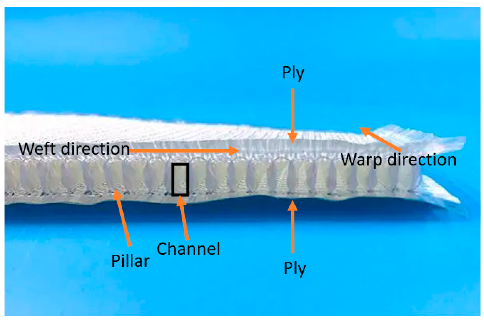
The 3D fabric, illustrated in Figure 1, consists of two plies of bidirectionally woven fabrics interconnected by vertical fibers (pillars). The length of these pillars determines the space between the two fabrics. When impregnated with resin, the pillars expand, creating the specified gap between the fabrics. This woven pillar-to-fabric connection significantly enhances overall stiffness and interlaminar strength, rendering a 3D glass–epoxy panel with a significantly stronger bending stiffness than its equivalent 2D counterpart. However, for thinner 3D fabrics like the one in this study, stiffness differences are not significant. Hence, a cost-effective wooden dowel reinforcement is introduced to substantially increase both the strength and stiffness of the 3D glass–epoxy, as will be demonstrated later. Thicker fabrics, especially when combined with the lightweight system used here, would yield even greater stiffness gains. For more insight into the performance of the 3D fabric, the reader is directed to reference [15].
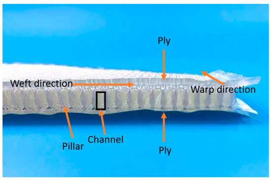
Figure 1.
Illustration of component names in the 3D glass fabric [16].
Figure 1 depicts a typical 3D fabric with hollow channels created by plies and pillars. Wooden dowels are inserted into these channels before cloth impregnation, resulting in a more robust and stiffer 3D hybrid composite material. The benefits of using wood were previously discussed. The mechanical properties of the fabric and dowels are reported in Table 1.

Table 1.
Refined material properties used in flexural and compressive models.
This research aimed to assess the feasibility of using the developed 3D hybrid material to create poles with superior stiffness compared to equivalent-weight 2D poles. Scaled 2D and 3D poles were designed and fabricated to evaluate the proposed design against the latest commercially designed 2D modular poles. It is worth noting that automating dowel embedment during 3D fabric manufacturing/weaving could facilitate mass production. Additionally, the study developed a simple equation for pole designers to estimate the equivalent stiffness of a given 3D pole.
Due to the geometrical configuration of this hybrid composite, it would not be feasible to evaluate its tensile strength using the conventional test method as that in the ASTM D638 or D3039 test guidelines. Therefore, the flexural and compressive properties of this composite were evaluated experimentally.
3. Evaluation of the Bending and Compressive Response of 3DdrFRP
It is well established that the Achilles heel of most FRPs is the delamination phenomenon, due to the relatively much weaker resin constituent and the mismatch in mechanical properties exasperated due to the stacking sequence. FRPs are quite susceptible to delamination under compressive and bending loads. The inherent nature of the 3D woven fabric significantly decreases the likelihood of delamination compared to its 2D layered counterpart. Nonetheless, the response of the material subjected to the aforementioned loading states should be examined, especially the existence of any voids and deformations induced on the empty channels of the fabric due to the consolidation process (i.e., the application of shrink wrap) that can potentially initiate the delamination and local buckling of the fabric on the non-Dowell-filled sections. In this section, therefore, the bending and compressive response of the hybrid composite is evaluated based on the ASTM standards.
3.1. Specimen Preparation
Initially, 3D glass fabric sections measuring 200 × 150 mm (in the weft and warp directions) were prepared for each test category. The dowels were Ramin hardwood with a 3.175 mm diameter and length of 1200 mm. The dowels were not pretreated using any chemical or coating. The dowels were purchased from a local hardware store; therefore, no specific information was available for them. It is worth noting that the 3.175 mm diameter dowels used were slightly larger than the untreated fabric’s channel dimensions, necessitating careful insertion into every other channel along the warp direction. It should also be noted that the dowels play a major role in the performance of the new hybrid composite. Not only do they facilitate the consolidation of the 3D composite, but they also have a major contribution in stabilizing the pillars, hence strengthening and stiffening the response by significant percentiles, as reported earlier. Moreover, as explained in Section 1.2, the integral woven nature of the pilar/cross-ply feature of this 3D fabric virtually eliminates the potential for delamination.
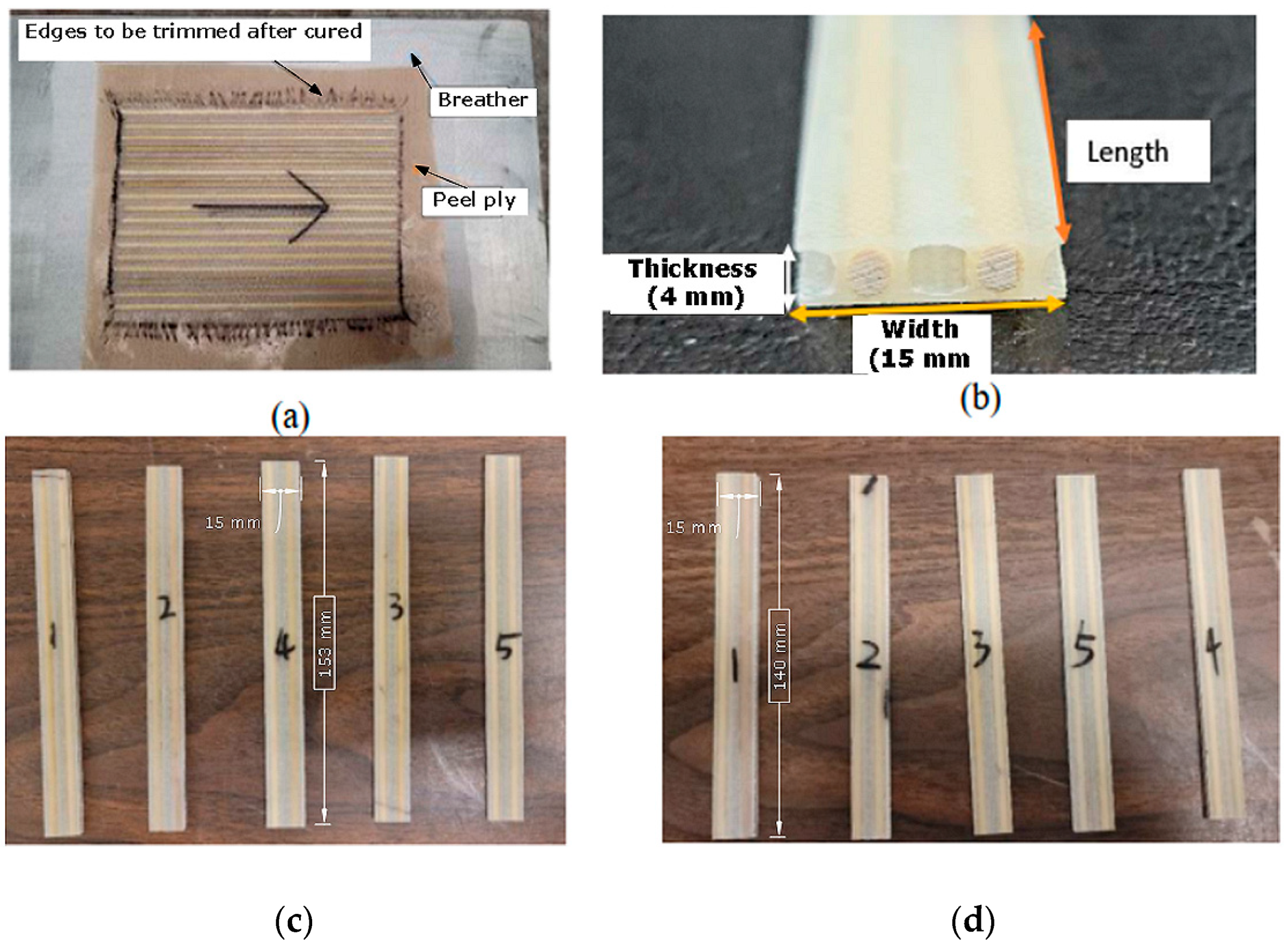
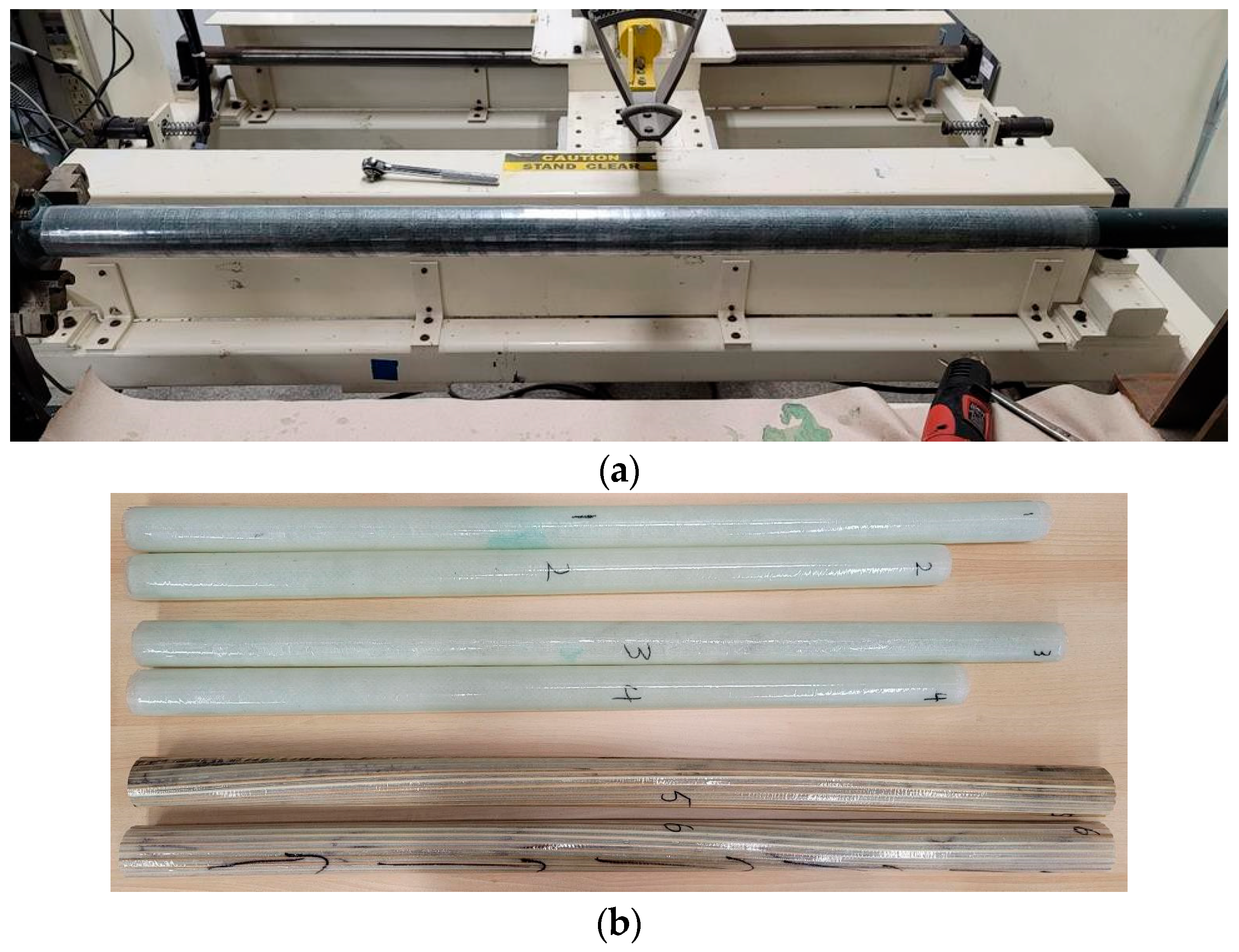
West System 105 room-cured resin and 206 hardener [17] were mixed at a 5:1 ratio, brushed onto peel ply, and left to cure for 24 h. The resulting panels had excess fibers at the edges (see Figure 2a), which were trimmed using a rotary diamond saw. The panels were then cut into appropriately sized specimens following ASTM D7264 [18] and ASTM D6641 [19] for compressive and flexural tests, respectively. Each specimen or coupon featured one mid-width empty channel surrounded by two dowel-inserted channels and a half-width empty channel on the exterior edges. Five coupons per test category were extracted from the panels, measuring 150 mm for three-point bending tests and 140 mm for compressive tests following ASTM standards.

Figure 2.
Prepared specimens: (a) typical 3D-drFRP panel being prepared, (b) a typical coupon’s cross-section (c) flexural test specimens, and (d) compressive test specimens.
3.2. Three-Point Flexural Test
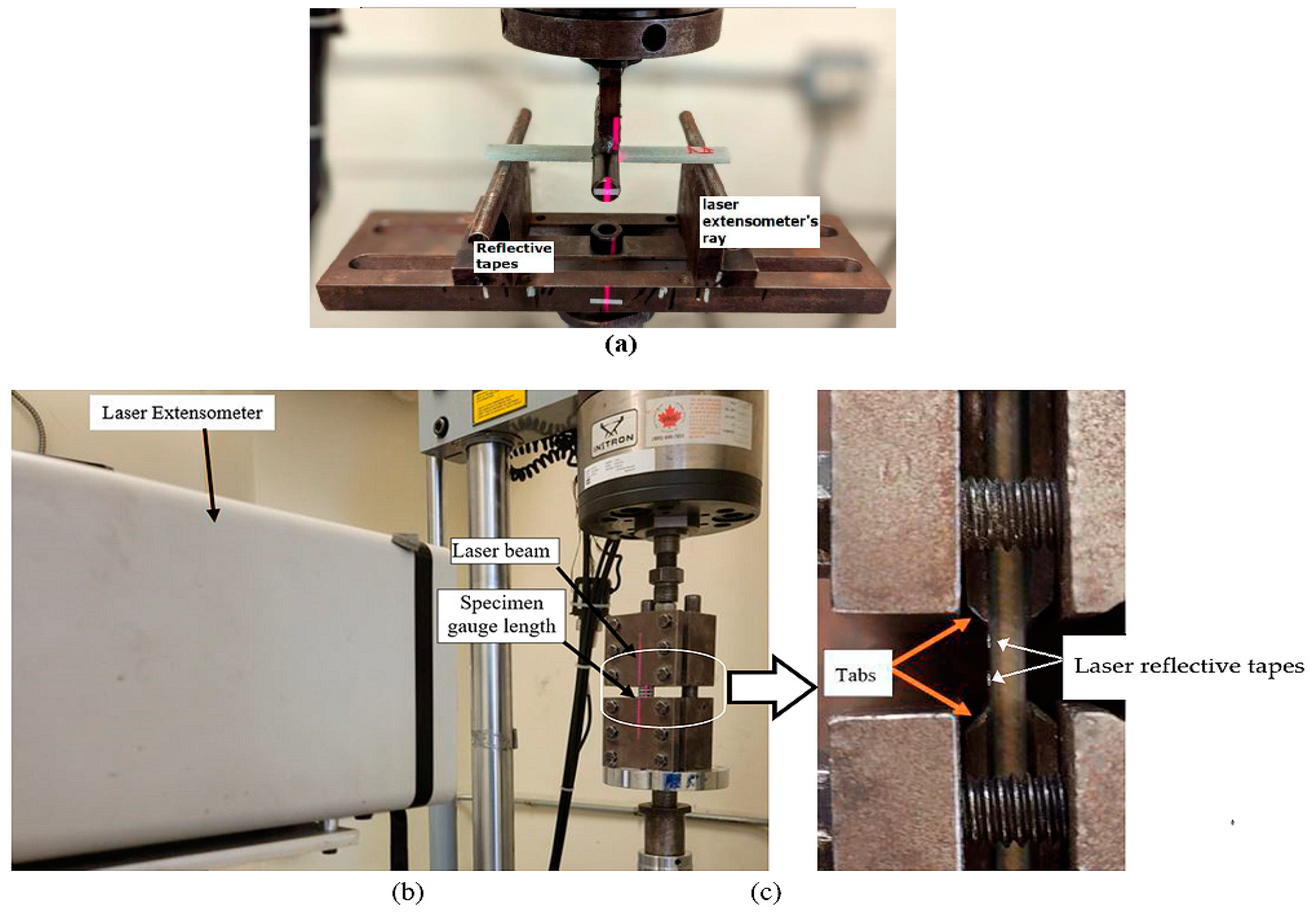
Bending tests followed ASTM-D7264 [18] procedure A. Specimens had average dimensions of 153 mm in length, 15 mm in width, and 4 mm in thickness, with a support span of 128 mm, as illustrated in Figure 2. A loading speed of 1 mm/min was set, initially allowing for a maximum actuator displacement of 10 mm, where the initial failure occurred at 9.2 mm. The maximum actuation displacement was then increased to 25 mm to capture the full response of the remaining specimens. The deflection was recorded using both the test machine’s actuator and a Laser extensometer (see Figure 3). Subsequently, the flexural rigidity (EfI) could be calculated using Equation (1) [20]:
where F is the applied load, L is the support span, I is the area moment of inertia, and δ is the deflection corresponding to load F (taken at the linear portion of the load vs. deflection curve).
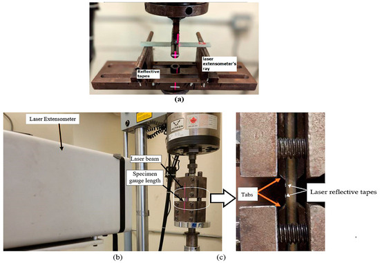
Figure 3.
Test setup: (a) flexural; (b) compression; (c) closeup view.
3.3. Compression Test
The compression test utilized the Combined Loading Compression (CLC) fixture as shown in Figure 3 (see ASTM-D6641 [19]). Five coupons were tested, measuring an average length, width, and thickness of 140 mm, 15 mm, and 4 mm, respectively. A laser extensometer measured the axial compressive strain at the 13 mm gauge length established using the following equation, as per ASTM D6641 [19]:
where lg is the gauge length, Fcu is the estimated ultimate compressive strength, Gxz is the estimated interlaminar shear modulus, and Ef is the estimated flexural modulus. Rough estimates were established for Fcu = 50 MPa and Gxz = 1000 MPa. Then, by inputting Ef = 6199.9 MPa as stated in Equation (2) and lg = 13 mm to the rest of the unknowns in Equation (2), the estimated specimen thickness, h, would have to be at least equal to or greater than 1.2 mm. Therefore, the 4 mm thick specimens satisfy the requirement. Tests were conducted at a rate of 1.3 mm/min until failure.
4. Results for the Basic Mechanical Performance of the Material
4.1. Flexural Test Results
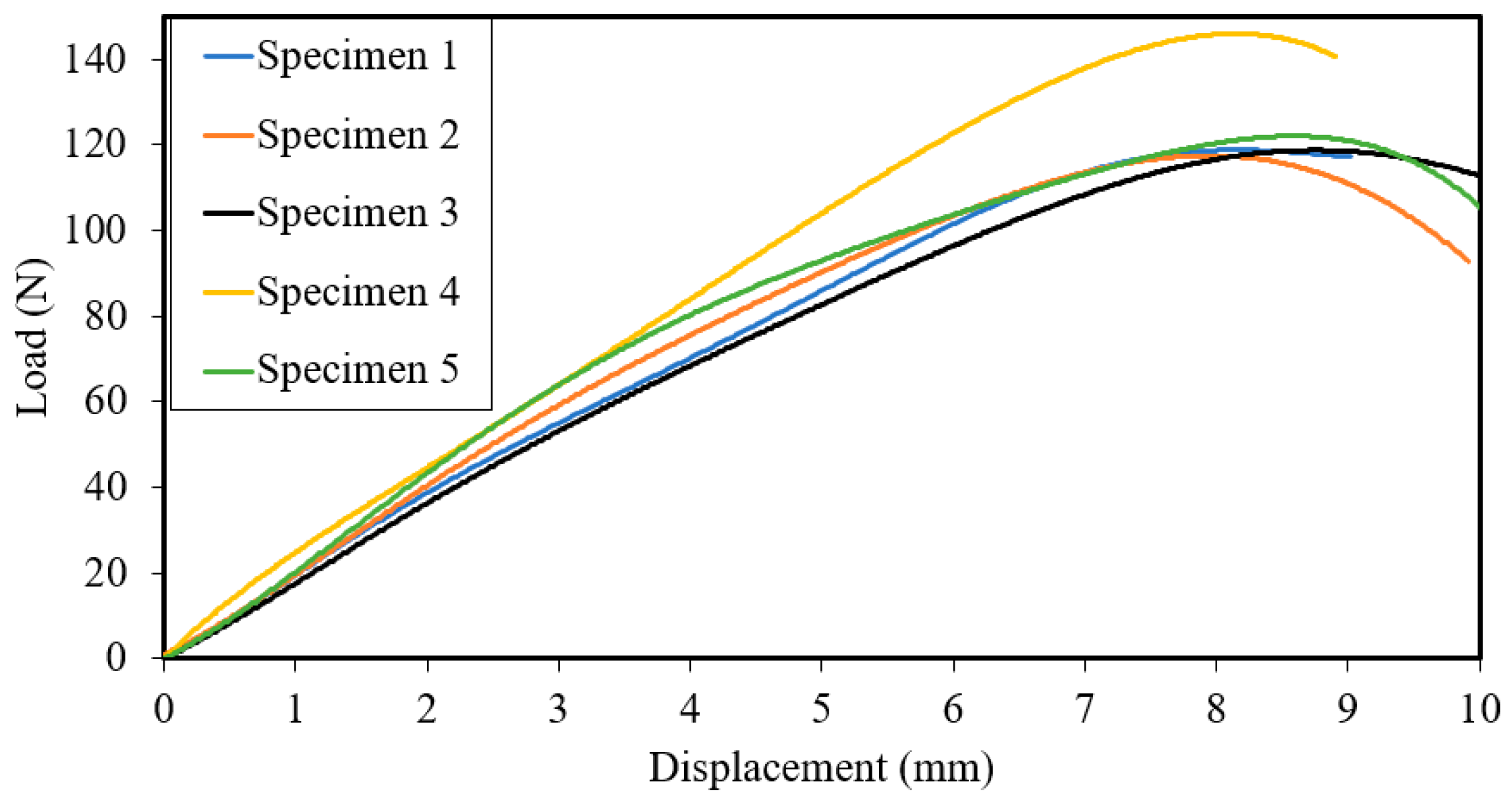
Figure 4 presents the experimental load–displacement curves. The flexural test results were processed, with an average ultimate load and strength of 121 and 117 MPa, respectively, a maximum displacement of 7.9 (mm), an elastic modulus of 10,267 (MPa), and a flexural rigidity of 679,683 (N·mm2).
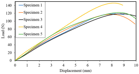
Figure 4.
Flexural tests’ load–displacement curves.
Variations in the load–deflection curves are attributed to fabrication-related anomalies like non-uniform void and resin distributions common in hand layup processes, particularly those without vacuum assistance. Despite being fabricated using the hand layup method without vacuum assistance, the results are reasonably consistent.
Figure 5 illustrates typical damage in specimens tested in flexure. The ply region on the bottom surface (tension side) of a flexural specimen, particularly at the mid-span and mid-width (corresponding to an empty channel location), is the most vulnerable to damage.
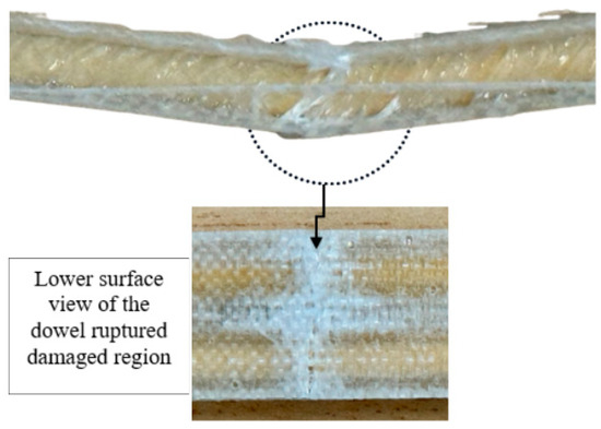
Figure 5.
Typical post-failure damage of a flexural specimen.
4.2. Compression Test Results
The results from the compression tests are shown in Figure 6a. The average ultimate compressive load is 2841 N, and the ultimate compressive strain is 1.44%, leading to a compressive elastic modulus of 8968 MPa. Moreover, as seen, compression specimen 1 exhibited the second-lowest elastic moduli while displaying the most ductile response. The standard deviation of maximum strength, at 7.7 MPa, is considered reasonable given the material’s complexity and experimentation conditions. The discrepancies in the experimental results are due to the reasons stated above. The results show an elastic response up to a displacement of approximately 0.1 mm, after which it deformed nonlinearly as the dowels started failing. The typical mode of failure of specimens tested under compressive loading, which was in the form of a shear-crimping failure mode is Figure 6b.
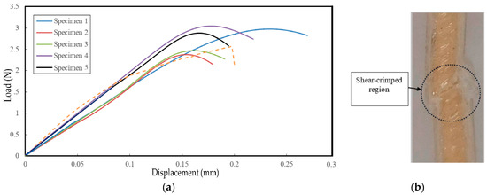
Figure 6.
(a) Compression tests’ load–displacement curves; (b) typical failure mode of specimens tested in compression.
5. 2D Pole Design
This section introduces two types of scaled-down composite poles: conventional 2D FRP (glass–epoxy) poles, similar to the commercially available ones, and the novel 3D-drFRP material. These poles are referred to as 2D and 3D poles hereafter, respectively. Notably, 2D poles are modular in design, while the inherent complexities of 3D fabric and dowel reinforcements necessitate prismatic shapes for 3D poles.
2D Scaled Modular (Tapered) Pole Design
In the context of composite poles, assessing hoop strength is crucial to preventing local buckling, especially at the groundline boundary. Moreover, investigating interlaminar failures is essential, as composites are vulnerable in this aspect. Therefore, a nonlinear numerical analysis was conducted using LS-Dyna software, with a sophisticated material model capable of handling failure criteria, the degradation of the material, and element erosion. The layup considered included unidirectional (UD) and [0/90] cross-ply E-glass fabrics to examine interlaminar failure potential. The selected layup, [+/09/+], with a slightly lower axial stiffness but greater resistance against local buckling, was chosen for pole fabrication. Seven laminated configurations were analyzed, and the [+/09/+] layup was found suitable.
As stated earlier, a modular design was implemented for these poles, considering the advantages outlined in Section 1. Due to experimental and fabrication limitations, each module’s maximum length was set to 1000 mm, allowing for a maximum of two modules per pole. The performance of the modular design was compared to RS Technologies Inc.’s commercial pole design and other reported scaled pole designs. Control over the overlap region in the modular design was deemed critical, as it is a high-stress area. The overlap length should be at least 1.5 times the diameter of the upper module at the bottom, as per ASCE [7], and can be calculated using the following equation:
where L is the pole’s length, t is the pole thickness, and θ is the tapered angle in degrees (please see Figure 7).
overlap length = L − tan(θ)
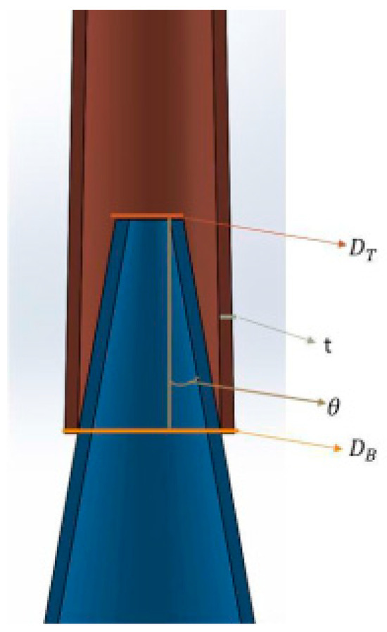
Figure 7.
Schematic of the overlap region and its parameters (angle Ɵ has been exaggerated for visual purposes).
The diameter of the cross-section at the top of each module, DT, can be evaluated based on the base diameter, DB, using the following equation:
DT = DB − 2L tan(θ)
The dimensions of the modular poles calculated according to the above equations are reported in Table 2.
Table 2.
The designed modular pole dimensions.
Subsequently, after the assemblages of the two modules of the proposed design, all of the pole’s parameters were compared against those of the full-sized commercial pole (RS Technologies Inc, n.d.) and two scaled poles from existing studies, as reported in Table 3.
Table 3.
Comparison of the proposed pole’s key parameters with those of a commercial pole and scaled poles investigated in other studies.
6. 3D Scaled Pole Design
6.1. Preliminary Coupon-Level Investigation
This work introduces two significant innovations: (i) the utilization of 3D fabric in the development of durable poles, which is a novel approach; and (ii) the reinforcement of the fabric with wooden dowels to enhance overall stiffness.
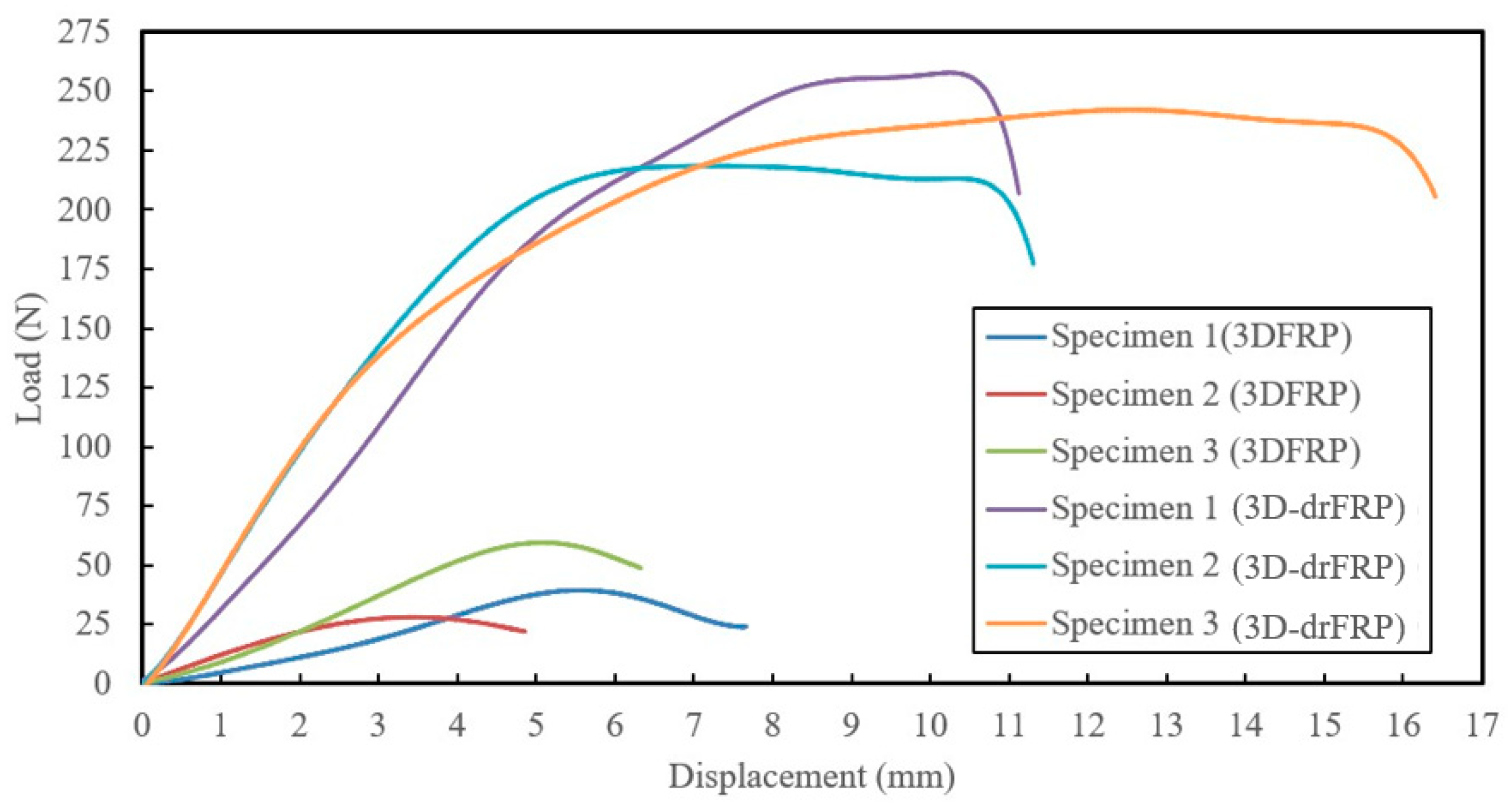
Before designing and fabricating the 3D pole, the response of the new 3D-drFRP material was assessed against its 3DFRP counterpart. Curved cross-section specimens were fabricated from both materials and subjected to three-point bending tests to measure the enhancement in the response of the 3D-drFRP. These specimens were obtained from cylinders made of the two materials. The results, as shown in Figure 8, reveal a significant improvement in the response of the 3D-drFRP due to the incorporation of dowels, with an approximate 300% increase in stiffness and 500% increase in strength.

Figure 8.
Responses of 3DFRP and 3D-drFRP coupons under flexural loading state.
6.2. Design Compromise
In the context of tapered poles, where the top and bottom diameters differ, constructing a 3DdrFEP pole would result in an unequal number of channels at the top and bottom. This necessitates a partial cutting of the dowels along the pole’s length, making fabrication impractical and diminishing dowel contributions, leading to inconsistent stiffness along the pole’s length. Consequently, a prismatic pole design was adopted as a practical compromise, featuring specific dimensions and a slenderness ratio. The pole was designed as 1000 mm long, has an outside diameter of 56.5 mm, a thickness of 5 mm, and a slenderness ratio of 115.5.
7. Fabrication of the Poles
7.1. 2D Pole Fabrication
Poles are often manufactured via filament winding, which is an automated manufacturing process [22], requiring expensive filament winding equipment that was not available to us. Pultrusion is another automated fabrication process that can be used to effectively produce prismatic sections [23], including cylindrical sections as composite poles. However, the new trend in pole design, favoring non-prismatic shapes, makes the incorporation of pultrusion for manufacturing tapered poles challenging. As a result, while all modular and most prismatic composite poles are essentially manufactured using filament winding technology, single-piece poles, as well as cross arms, are manufactured using the pultrusion process [24].
To fabricate the poles and achieve the desired thicknesses for the nesting modules, extensive trials were conducted with cylindrical shapes. Ultimately, the [+/0/+] layup was selected due to its capacity to provide thickness tolerance in scaled poles for a sufficient overlap length. The fabric layers’ overlaps were alternately distributed at 120° angles around the circumference.
For the 2D pole modules, a solid cylindrical PVC stock was machined into a tapered shape. Initially, a wet-layup method was attempted but proved inadequate for effective consolidation. Prepregs, typically cured at high temperatures, could not be used due to the unavailability of a suitably sized oven. Therefore, an innovative pseudo-prepreg approach was developed in the lab. E-glass fabrics were saturated with West System 105 resin and 206 slow hardener, laid as per the designed stacking sequence, covered with plastic sheets, and placed in a freezer. At the pole fabrication stage, the prepreg was removed from the freezer and allowed to warm up gradually from frozen to a “tacky” state. Then, the pre-impregnated fabrics were wrapped around a mandrel, tensioned, and finally secured using shrink tape (see Figure 9a) and left to cure at room temperature. Four modules were created using these steps. Each two modules were joined together with a thin epoxy layer to enhance load transfer and form a 2D modular tapered pole. Two tapered poles were assembled from these modules, reflecting the design’s performance.
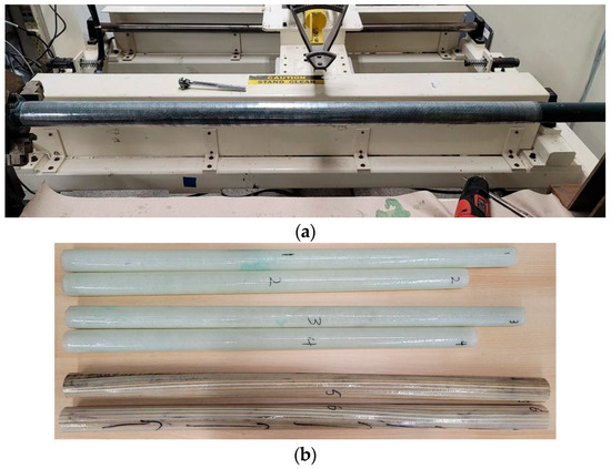
Figure 9.
(a) A pole module being fabricated, wrapped with shrink tape; (b) 3D and 2D poles (numbers signify pole numbers).
7.2. 3D Pole Fabrication
A total of two 3D poles were fabricated. The fabric was turned into prepreg following the same procedure described previously. The poles were also fabricated using the same procedure discussed in the last section with one difference in that before the 3DdrFRP prepreg was wrapped onto the mandrel, a layer of resin was brushed on the mandrel to ensure better wetting of the inner surface of the pole (see Figure 9a). The dimensions of the fabricated 3D poles are reported in Table 4. All the produce poles are shown in Figure 9b.
Table 4.
Measured dimensions of the fabricated FRP pole modules.
7.3. Loading Mechanism
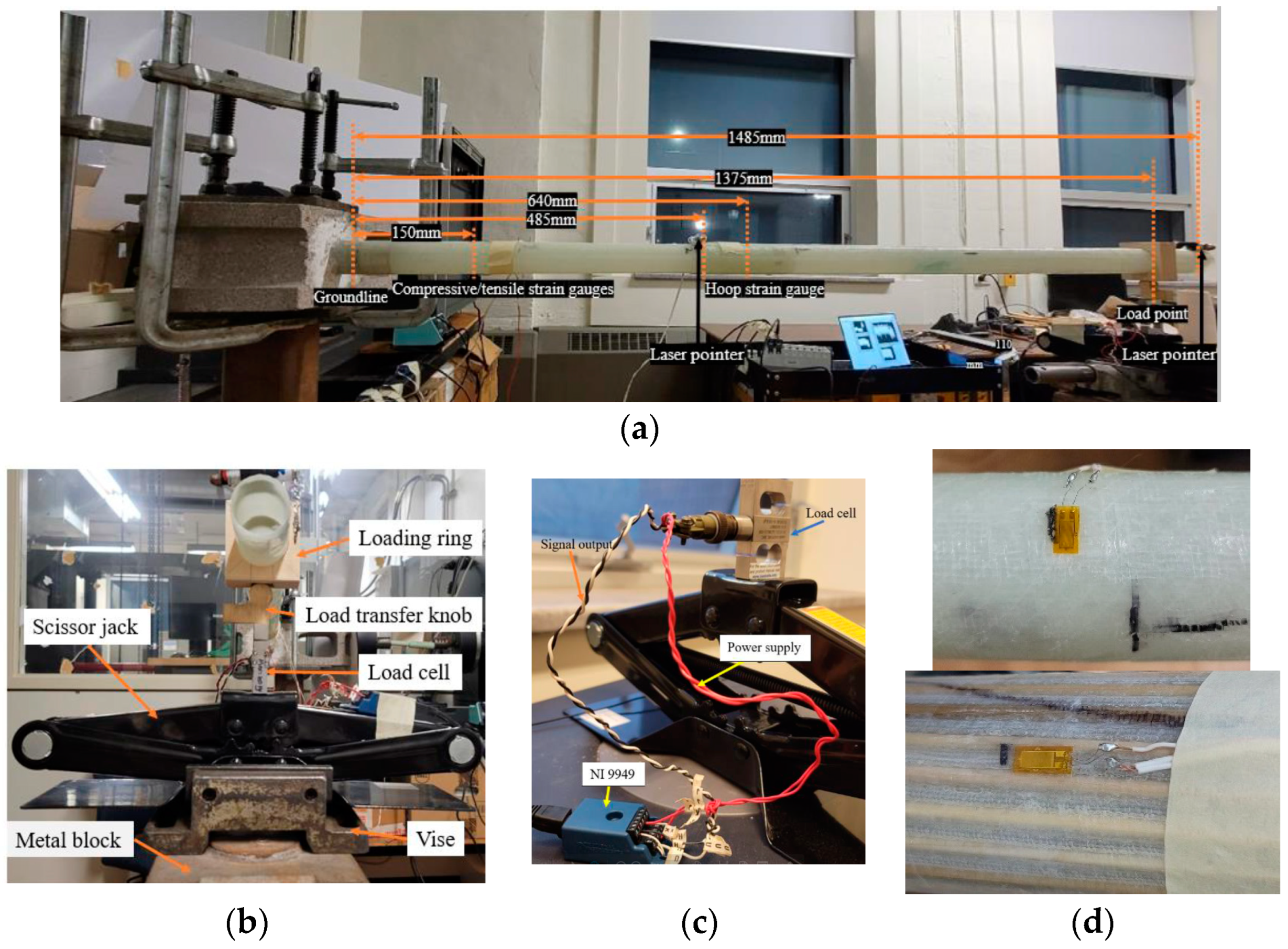
The overall test setup is shown in Figure 10a. The setup includes a full-bridge 100 Kgf capacity OMEGA LCM/111-100 load cell from Omega Sensing Solutions [25], which was used to measure the applied load, controlled by a scissor jack. The load cell was connected to the DAQ system using appropriate modules, as depicted in Figure 10b.
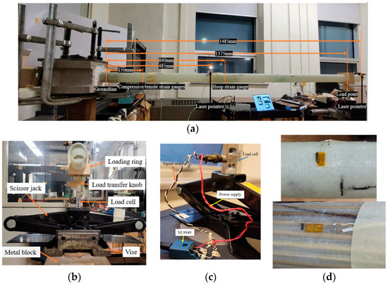
Figure 10.
(a) Overall test setup, (b) detail of the loading setup (side and isometric views), (c) close-up of loading jack and its instrumentation; (d) hoop-measuring strain gauge on 2D (top) and longitudinal measuring strain on a 3D pole (bottom).
7.4. Data Acquisition
Individual 350 Ω quarter-bridge strain gauges (OMEGA SGD-10/350-LY41) were employed [24] to measure the tensile and compressive strains on all poles, as well as hoop strains on the 2D poles. Due to the 3D poles’ thick-wall design, which minimizes the risk of local buckling, hoop strain was not monitored. Strain values were recorded using a Compact DAQ NI Chassis cDAQ-9172 system from National Instruments [26]. For the 2D poles, two strain gauges were placed 150 mm above the groundline on the tensile and compressive sides. The strain gauge measuring hoop strain due to the compressive load was positioned 155 mm above the lower end of the top module. The locations of the strain gauges for both the 2D and 3D poles are illustrated in Figure 10a.
8. Experimental Results and Discussion
The cantilever tests, as shown in Figure 10a, employed manual displacement tracking at the pole’s tip and mid-span using orthogonal laser pointers. These pointers were affixed at the mid-span, aligning with the top module’s butt end, as depicted in the figure, as well as at the tips of the poles. The trajectories of these laser pointers were traced onto whiteboards and marked at specific load intervals using pins. Data acquisition monitored the strain gauges and load cells through a code written in the LabView environment; it was used to oversee processes like the start/end of acquisition, sampling rate evaluation, data storage, and transducer calibration.
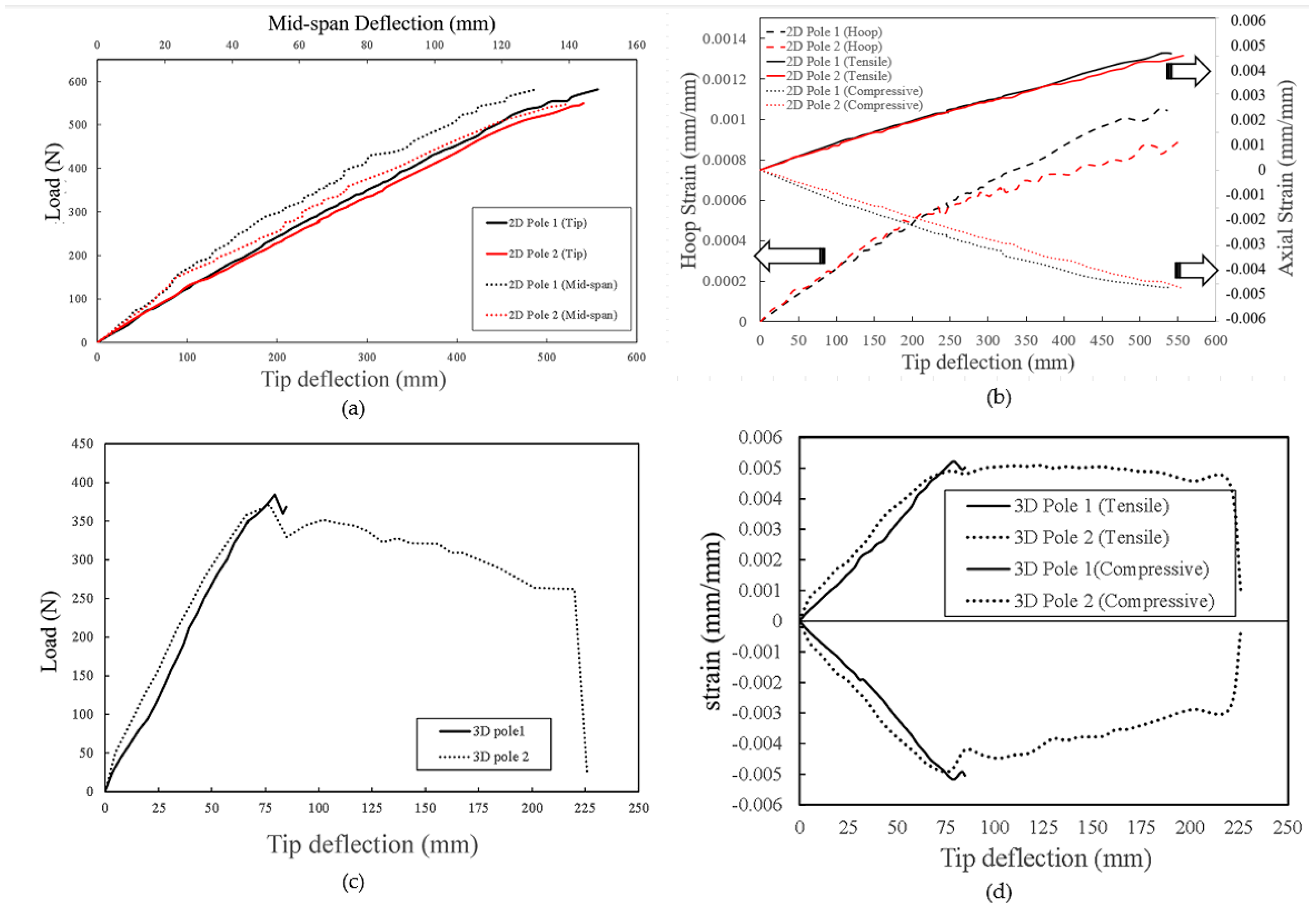
During testing, a scissor jack was used to steadily raise the pole’s tip at a consistent speed of 0.25 mm/sec, pausing after every three complete jack rotations to record displacements and corresponding loads until test completion. The experimental results, including load, deflection, and longitudinal compressive/tensile and hoop strain distributions were monitored and are presented in Figure 11.
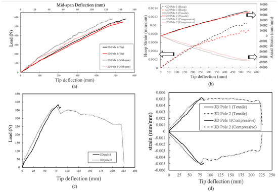
Figure 11.
Performances of the poles: (a) load–deflection and (b) strain–deflection plots of 2D poles; (c) load–deflection and (d) strain–deflection plots of 3D poles.
It should be noted that when testing the first 3D Pole, the loading jack reached its maximum travel limit unexpectedly due to significant deflections. Subsequent tests involved releasing the load and inserting a series of 25 mm thick steel plates under the jack to continue testing. Furthermore, the failure of the 2D poles could not be observed due to their unanticipated very large deflection, and further loading could have posed a catastrophic risk to the loading mechanism.
Notably, the 3D poles exhibited significantly stiffer responses, enduring an average ultimate compressive strain of 0.005 mm/mm. Compressive strain values for both 3D poles began decreasing at deflections coinciding with load decreases. As seen in Figure 11, nonlinear mid-span curves partly resulted from measurement resolution, where deflection changes at such low values were smaller than the laser beam’s projected radius on the whiteboard. Using a Linear Variable Differential Transformer (LVDT) or a more focused laser pointer could have improved the accuracy. An available LVDT in the lab had a limited stroke range for observed deflections.
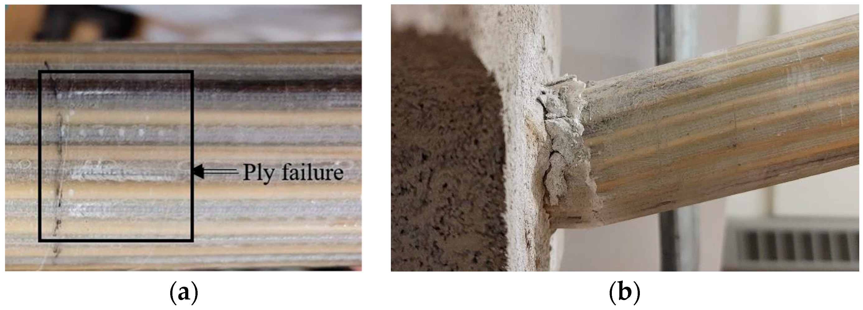
As seen in Figure 12, the 3D pole sustained significant loads after reaching ultimate strength, gradually decreasing to 262 N before full fracture at a 220 mm deflection. Concurrently, ply failure occurred 30 mm above the groundline along an empty channel on the compression side, as shown in Figure 12a, followed by compression failure at the groundline post fracture, as depicted in Figure 12b.

Figure 12.
Typical experimentally observed (a) ply failure and (b) pole failure.
To better understand the performance of the two pole types, their ultimate strengths were normalized to their masses. However, direct comparison was challenging due to differences in length and shape since the 3D poles tested were shorter and prismatic, while the 2D poles were longer and non-prismatic. To address this, a numerical simulation of a 3D pole matching the length of a 2D pole was conducted, and the detailed comparative results are provided in the second part of this paper.
Additionally, an accurate and straightforward hand calculation method was developed to estimate the stiffnesses of 3D-drFRP material poles. The comprehensive details of this method, constrained by space limitations, are presented in the second paper.
9. Conclusions
This study introduced a novel hybrid material, 3D dowel-reinforced FRP (3D-drFRP), consisting of 3D glass fabric–epoxy composite with wooden dowel reinforcement. The aim of the work introduced in this paper was to introduce a concept and examine its potential application for future developments. Additional examinations such as the investigation of long-term durability, adaptability to different environmental conditions, dynamic performance, and damping characteristics of the hybrid composite material, as well as its material and automated production cost, will be investigated. Moreover, poles may be subjected to large impact loading due to careless driving accidents and other reasons. Therefore, it is imperative to better understand the residual strengths of poles after failure, a critical topic that should be investigated.
The key findings and outcomes can be summarized as follows:
- -
- The assessment of 3DdrGRP’s mechanical properties revealed significant improvements in stiffness and strength compared to its non-dowel-reinforced 3DFRP counterpart, with enhancements of up to 300% and 500%, respectively. Additionally, there was a 13% difference observed between the flexural modulus and compressive modulus.
- -
- Computational simulations suggested that optimized designs could be achieved using either [+/09/+] or [90/011/90] layup sequences.
- -
- The paper detailed the development methods for both 3D and 2D poles. The experimental results highlight the impressive stiffness of 3D-drFRP material-based poles compared to that of conventional 2DFRP poles. However, 2D poles exhibited a higher load capacity. The lower load capacity of 3D poles was attributed to the premature failure of empty channels in the 3D-drFRP material, suggesting that additional dowel reinforcements could significantly enhance their load-bearing capacity.
In conclusion, this research demonstrates the promise of the developed 3D poles, especially in scenarios involving loading conditions that prioritize stiffness (e.g., axially applied dynamic loading states). Further investigations are warranted to explore their potential applications fully.
Author Contributions
Q.W.: Fabrication and Experimentation, Formal Analysis, Visualization, Data Curation, and Writing Original Draft; F.T.: Conceptualization, Methodology, Formal Analysis, Validation, Resources, Supervision, Writing—Final Draft; Writing—Review and Editing, and Funding Acquisition. All authors have read and agreed to the published version of the manuscript.
Funding
Funding was provided to the second author by the Natural Sciences and Engineering Research Council of Canada (grant No. RGPIN-2017-05114), which is gratefully appreciated and acknowledged.
Data Availability Statement
The data presented in this study are available on request from the corresponding author.
Acknowledgments
The financial support from the Natural Sciences and Engineering Research Council of Canada is gratefully appreciated.
Conflicts of Interest
The authors declare no conflict of interest.
References
- North American Wood Pole Council. How Wood Utility Poles Are Made. Available online: https://woodpoles.org/Why-Wood-Poles/How-Poles-Are-Made (accessed on 3 April 2023).
- Mankowski, M.; Hansen, E.; Morrell, J. Wood pole purchasing, inspection, and maintenance: A survey of utility practices—ProQuest. For. Prod. J. 2002, 52, 43–50. [Google Scholar]
- Love, L.; Post, B.; Tekinalp, H.; Wang, P.; Atkins, C.; Xianhui, A.R.; Zhao, A.; Rencheck, M. Assessment of Commercial Composite Power Pole Performance. 2021. Available online: http://www.osti.gov/scitech/ (accessed on 1 December 2023).
- El-Fiky, A.M.; Awad, Y.A.; Elhegazy, H.M.; Hasan, M.G.; Abdel-Latif, I.; Ebid, A.M.; Khalaf, M.A. FRP Poles: A State-of-the-Art-Review of Manufacturing, Testing, and Modeling. Buildings 2022, 12, 1085. [Google Scholar] [CrossRef]
- Palucka, T.; Bensaude-Vincent, B. History of Composites—Overview. Available online: https://authors.library.caltech.edu/5456/1/hrst.mit.edu/hrs/materials/public/composites/Composites_Overview.htm (accessed on 12 October 2022).
- ANSI/ACMA/UCSC UP01-18-2019; Standard Specification for FRP Composite Utility Poles. American National Standards Institute: Washington, DC, USA, 2019.
- ASCE. Recommended practice for fiber-reinforced polymer products for overhead utility line structures. In Recommended Practice for Fiber-Reinforced Polymer Products for Overhead Utility Line Structures, 2nd ed.; Fecht, G., Ed.; American Society of Civil Engineers (ASCE): Reston, VA, USA, 2019. [Google Scholar] [CrossRef]
- Morrell, J.J. Wood Pole Maintenance Manual, 2012 ed.; Oregon State University: Corvallis, OR, USA, 2012; Available online: https://www.forestry.oregonstate.edu/ (accessed on 11 July 2022).
- Jackson, E. Wood Utility Poles and Preservative Choices. Utility Products. Available online: https://www.utilityproducts.com/line-construction-maintenance/article/16002743/wood-utility-poles-and-preservative-choices (accessed on 2 June 2012).
- Rey, J.; Morrell, J. Estimated Service Life of Wood Poles. Available online: https://woodpoles.org/portals/2/documents/TB_ServiceLife.pdf (accessed on 17 January 2022).
- RS Technologies Inc. RS PowerONTM Modular Poles Brochure. Available online: https://www.rspoles.com/resources/literature (accessed on 5 April 2023).
- CSA C22.3; Overhead Systems C22.3. National Standard of Canada: Ottawa, ON, Canada, 2020.
- ASTM D1036; Static Tests of Wood Poles. American National Standards Institute: Washington, DC, USA, 2017.
- Ibrahim, S.M. Performance Evaluation of Fiber-Reinforced Polymer Poles for Transmission Lines. Ph.D. Thesis, The University of Manitoba, Winnipeg, MB, Canada, 2000. Available online: https://www.collectionscanada.gc.ca/obj/s4/f2/dsk1/tape3/PQDD_0025/NQ51638.pdf (accessed on 7 November 2022).
- Asaee, Z.; Taheri, F. Characterization of the Mechanical and Impact Response of a New-Generation 3D Fiberglass Fabric. In Proceedings of the American Society for Composites 30th Technical Conference, East Lansing, MI, USA, 28–30 September 2015. [Google Scholar]
- China Beihai Fiberglass Co., Ltd. 3D Fiberglass Woven Fabric. Available online: https://www.fiberglassfiber.com/3d-fiberglass-woven-fabric-product/ (accessed on 21 April 2023).
- West System. 05 Epoxy Resin®/206 Slow Hardener®. 2014. Available online: https://www.westsystem.com.au/wp-content/uploads/2019/07/WEST-SYSTEM-105-Epoxy-1 (accessed on 21 February 2024).
- ASTM D7264; Standard Test Method for Flexural Properties of Polymer Matrix Composite Materials: Vol. 15.03. ASTM International: West Conshohocken, PA, USA, 2015. [CrossRef]
- ASTM D6641; Standard Test Method for Compressive Properties of Polymer Matrix Composite Materials Using a Combined Loading Compression (CLC) Test Fixture: Vol. 15.03. ASTM International: West Conshohocken, PA, USA, 2015.
- Hibbeler, R.C. Mechanics of Materials, 10th ed.; Pearson: Indianapolis, IN, USA, 2016. [Google Scholar]
- Altanopoulos, T.I.; Raftoyiannis, I.G.; Polyzois, D. Finite element method for the static behavior of tapered poles made of glass fiber reinforced polymer. Mech. Adv. Mater. Struct. 2021, 28, 2141–2150. [Google Scholar] [CrossRef]
- Mazumdar, S.K. Composites Manufacturing: Materials, Product, and Process Engineering, 1st ed.; CRC Press: Boca Raton, FL, USA, 2002. [Google Scholar]
- Vedernikov, A.; Gemi, L.; Madenci, E.; Onuralp Özkılıç, Y.; Yazman, Ş.; Gusev, S.; Sulimov, A.; Bondareva, J.; Evlashin, S.; Konev, S.; et al. Effects of high pulling speeds on mechanical properties and morphology of pultruded GFRP composite flat laminates. Compos. Struct. 2022, 301, 116216. [Google Scholar] [CrossRef]
- EPRI. Management of Composite Structures. Available online: https://www.epri.com/research/products/000000003002020576 (accessed on 17 January 2022).
- Omega Sensing Solutions ULC. Available online: https://www.omega.ca/en/ (accessed on 17 January 2022).
- National Instruments Corp. Connecting Strain Gauges and Shunt Resistors to the NI-9237. 2022. Available online: https://knowledge.ni.com/KnowledgeArticleDetails?id=kA00Z000000PA73SAG&l=en-CA (accessed on 17 January 2022).


Disclaimer/Publisher’s Note: The statements, opinions and data contained in all publications are solely those of the individual author(s) and contributor(s) and not of MDPI and/or the editor(s). MDPI and/or the editor(s) disclaim responsibility for any injury to people or property resulting from any ideas, methods, instructions or products referred to in the content. |
© 2024 by the authors. Licensee MDPI, Basel, Switzerland. This article is an open access article distributed under the terms and conditions of the Creative Commons Attribution (CC BY) license (https://creativecommons.org/licenses/by/4.0/).