Abstract
This study investigates the stability of Inconel–Cu Multimetallic Layered Composites (MMLCs) in nuclear reactor applications using Molecular Dynamics simulations. The focus is on understanding the underlying mechanisms governing the properties of MMLCs for advanced nuclear reactors, specifically, the mechanochemistry of the interface between Inconel and copper alloys. The selection of Inconel–Cu MMLCs is primarily due to copper’s superior thermal conductivity, enhancing heat management within reactors by preventing hotspots and ensuring uniform temperature distribution. This research examines Incoloy 800H and two Inconel variants (718 and 625), assessing their stability at 1000 K after exposure to 10 keV collision cascades up to 0.12 dpa. Notable findings include defect clustering on the {1 2 0} family of planes of Inconel and Cu, with Stacking Faults and Lomer–Cottrell locks on the Inconel side.
1. Introduction
Resistance to thermal and irradiation creep, high mechanical strength, creep resistance, fatigue resistance, radiation damage resistance, and chemical compatibility with the coolant and the fuel [1] are some properties the structural material for Gen-IV must have. Exposure to higher temperatures would cause hydrogen embrittlement in zirconium alloys [1]. As a result of these requirements, materials currently used for Gen-III reactors are unsuitable for use in Gen-IV reactors. Multimetallic layered composites (MMLCs), which decouple interactions between different alloys by forming functionally graded materials, provide a viable solution [2].
The austenitic nickel–chromium-based superalloys, such as Incoloy 800H [3], Inconel 718 [4], and Inconel 625 [5], are some of the candidate materials for Gen-IV reactors. Inconel has a high oxidation resistance, one of the primary features that any candidate for fuel cladding material must possess. Incoloy 800H has a high atomic weight percentage of iron (47%) and a comparable atomic weight percentage of nickel (32%) and chromium (21%). Incoloy 800H is predominantly employed in heat exchangers and industrial heating equipment [6], yet its applications in Gen-IV reactors have been reported and [7] comprehensively reviewed [8]. It was found that Incoloy 800H has a lower thermal conductivity and a higher resistance to temperature-induced corrosion [9], and it was found to be a viable option for VHTRs. Fine precipitates were observed to form in Incoloy 800H when subjected to irradiation at a temperature of 500 °C [10]. Laser cladding was used to improve the high-temperature oxidation characteristics of Incoloy 800H [11]. Inconel 718 has an atomic weight composition of 55% Ni, 21% Cr, and 24% Fe. At high temperatures, the self-diffusion of Ni atoms was observed to govern mechanical deformation in Inconel 718. Inconel 718, notable for its usage in turbocharger rotors and gas turbines, constitutes over 30% of the mass of modern aircraft engines [12]. Inconel 718 was found to be a highly suitable material to manufacture bellows in nuclear power plants owing to its compatibility with the coolant and its chemical inertness [13].
Similarly, Inconel 625 is instrumental in the marine and nuclear sectors [14,15]. Inconel 625 contains a very high atomic weight percentage of Ni (72%), a comparable concertation of Cr (23%), and a meager percentage of Fe (5%). It was initially meant to be used as a material for steam-line piping and is highly resistant to oxidation and corrosion. Its original composition was modified to make it weldable and even more creep-resistant [16]. The investigation into understanding the corrosion properties of Inconel 625 in a reactor environment [17] yielded results that indicated a high corrosion resistance up to a temperature of 1500°F. Inconel 625-clad steel possessed excellent corrosion resistance in severe environments in energy and processing industries [18]. The properties of Inconel have been studied to evaluate its use in the tokamak concept [19] of the nuclear fusion reactor. Inconel 625 was studied as the material in the neutron shielding structure of the vacuum vessel in the JT-60SU tokamak device [20]. Inconel 718 was used as a part of the inner wall and the outer wall structures in an Affordable Robust Compact (ARC) fusion reactor [21], where it was observed that Inconel 718 maintained a good degree of creep resistance to temperature until around 930 K.
The inclusion of copper in the composition of MMLCs under investigation is justified by its excellent corrosion resistance and the demonstrated irradiation resilience of copper-electroplated Zircaloy claddings [22,23]. The effect of copper addition on the oxidation of zirconium alloys used as nuclear fuel cladding materials [24,25] as well as the influence of copper on Zircaloy fuel cladding degradation [26] has already been investigated. It was also observed that the Ultimate Tensile Strength (UTS) and Yield Strength (YS) of zirconium (Zr) alloys had a considerable degree of dependence on their copper content [27]. Copper has been studied as a material used to make canisters to isolate spent nuclear fuel in the long term [26]. The influence of elevated temperature on Cu showed a linear degree of corrosion at the beginning and exponential kinetics of corrosion after prolonged exposure, which resulted in layers of cupric oxide (CuO) and cuprous oxide (Cu2O) [28]. The electrical impedance was determined to be affected by the growth and nucleation of deposits on the copper surface [29]. An explosively bonded laminated Inconel–Cu plate was used as the toroidal field and ohmic heating conductor material in a Compact Ignition Tokamak (CIT) to provide the conductors an enhanced conductivity/strength ratio [19]. Cu has a high thermal conductivity of ~390 W/mK, which is only second to silver among all metals. Its thermal conductivity is almost 30 times higher than that of stainless steel [30]. Incorporating Cu in a Fe-Cu bimetal provided high thermal conductivity in the heat sink since the quick dissipation of heat was facilitated by the Cu [31]. An increase in thermal conductivity and thermal diffusivity of ~65% and ~500%, respectively, was observed in the bimetallic Inconel 625–Cu structure in comparison with Inconel 625 [32]. GRCop-84, which contains ~87.5 wt.% of Cu, when added to Inconel 718 to create a bimetallic structure, resulted in a thermal diffusivity increase of ~250% as compared with the pure Inconel 718 structure [33].
When exposed to radiation, materials face radiation damage, resulting in the accumulation of defects such as voids, vacancies, and interstitials, which are fundamental radiation-induced atomic changes. These defects tend to impair the material’s mechanical and thermal properties, leading to performance degradation [34,35] and the structural integrity of the nuclear reactor. The formation of cracks further enhances the possibility of accidents. Here, we employed the Molecular Dynamics (MD) simulation technique to study irradiation effects on the stability and mechanical properties of irradiated Inconel–Cu MMLCs. This method has successfully formulated a theory that quantifies elastic interactions to describe homogeneous grain boundary phase nucleation at elevated temperatures [36]. In this work, we considered one Incoloy combination—i.e., Incoloy 800H—and two Inconel combinations, i.e., Inconel 718 and Inconel 625.
2. Materials and Methods
Three compositions of Inconel, namely, Incoloy 800H (Ni32Cr21Fe47), Inconel 718 (Ni55Cr21Fe24), and Inconel 625 (Ni72Cr23Fe5), for an 80 × 40 × 40 face-centered cubic (FCC) lattice structure of Cu with 512,000 atoms were considered, with both the Inconel and copper layers having a thickness of 144.32 Å each. This system size ensures that the collision cascades initiated by 10 keV Primary Knock-on Atoms (PKAs) have no interaction with the periodic images during the modeling of the collision cascades [37]. For constructing the atomistic model of the MMLC, the left half of the pre-existing copper slab was replaced with an equivalent Inconel segment, resulting in a structure composed of 256,000 Inconel atoms. This modification creates an Inconel–Cu composite characterized by a (100) crystallographic interface between the two metallic constituents. Upon irradiation, PKAs are generated, leading to lattice displacements within the irradiated structure. The determination of the damage caused by irradiation was performed by considering vacancies and formed defects using Seitz’s theory [38] of moving atoms. The initiation of this process occurs when an atom is perturbed from its original lattice site, which then imparts energy to neighboring atoms through collisional interactions, precipitating a cascade of subsequent atomic displacements. The PKA can induce multiple displacements of atoms in other lattice sites if it possesses an adequate amount of energy, or it can come to rest at an interstitial lattice site if it does not have enough energy [39]. We performed MD simulations using LAMMPS Version 3.7.8. [40]. The Inconel–Cu structure was initially relaxed at 1000 K [41], which is the operating temperature of fluoride salt high-temperature reactors, for 50 ps under NVT ensemble with a time-step of 1 fs. Ni atoms were selected as the PKA for the cascade simulation since it has the largest radiation surface of all the atoms in this model. The identification and analysis of the defects were performed using the Wigner–Seitz cell [42] method in OVITO version 3.7.8 [43].
In studying radiation effects on the Inconel–Cu heterostructure interface, the PKA velocity distribution is anisotropic [44]. The velocity magnitude is distributed as v = (0.99, 0.135, 0.042)|v| [44]. The velocity vector ‘v’ represents the distribution direction of the energy. The velocity magnitude corresponding to a 10 keV energy peak is predominantly oriented in the x-direction, which is normal to the Inconel–Cu interface. Using this energy distribution, the structure was homogeneously irradiated up to a radiation dose of 0.12 dpa. A microcanonical (NVE) ensemble was employed for the cascade simulation over a 20-picosecond duration, utilizing a variable time-step algorithm to optimize numerical efficiency. The PKA selection process is governed by a successive cascade algorithm, whereby a solitary atom within a stipulated spherical volume is designated as the PKA and endowed with the requisite energy of 10 keV to initiate bombardment processes [44,45,46,47,48]. The evolution of the collision cascade events happens in four stages, namely, the initial collision, thermal spike (TS), ballistic mixing, and annealing. During the initial collision stage, lasting 0.9–1.5 ps, energy dissipates, or further displacements occur, without defect clustering because of the brief duration. To prevent atoms from moving beyond 0.1 Å, the time-step is reduced to 0.01 fs from the usual 1 fs, resetting every 10 steps. The TS stage [49,50] involves the dissipation of the maximum cascade energy to neighboring atoms within ~1 ps of the PKA initiation, which results in the maximum displacement of the atoms. In this stage, there is a spike in the temperature in correlation to the 10 keV PKA energy that is provided. At the end of the collision cascade, the TS is quenched back to 1000 K. In the ballistic mixing stage, the Ni, Cr, and Fe atoms on the Inconel side diffuse gradually into the Cu side, facilitating the formation of several vacancies and interstitials. The final stage is the annealing phase, which is instrumental in causing defect displacement and annihilation. The collision damage becomes detectable in this phase. This phase lasts ~10 ps.
Interatomic forces within the four-element atomic system are characterized by an embedded atom method (EAM) potential [51]. EAM potentials can model the behavior of atoms in metals and alloys at the atomistic scale. It simulates many-body interactions by considering the local electron density around the atoms. The EAM potential is augmented with Ziegler–Biersack–Littmark (ZBL) parameters to enhance the fidelity of cascade simulations, especially for high-energy and short-range interactions [52,53]. ZBL potentials help model the interatomic interactions at distances where repulsion between atoms occurs and find utility in modeling atomic interactions during irradiation damage simulations. The expression that gives the total energy is
where the Heaviside function H(rij) ensures the seamless shift between the EAM and ZBL potentials. Since the first nearest neighbor atom distance is 0.707a, with a being the lattice constant, the inner and outer radii of the ZBL potential should be lower than this distance value. Knowing that the value of this distance for Ni is 2.49 Å, the inner and outer radii are chosen to be 0.9 Å and 1.25 Å, respectively [44].
To obtain the displacement per atom (dpa) for each PKA, two methods were employed, which were the Stopping and Range of Ions in Materials (SRIM) [52] code and the Norgett–Robinson–Torrens (NRT) equation [54]. The SRIM method is used to simulate the deposition trajectories and profiles of ions when they are exposed to high-energy beams. It also predicts the evolution of damage in materials subjected to impact from high-energy ions. There are two ways displacement damage parameters can be computed in SRIM, namely, the ‘Quick’ Kinchin Pease [55] calculation and the Full Damage Cascade calculation. The input parameters used were as follows: The input layers consisted of one layer of Incoloy 800H (Ni32Cr21Fe47) and one layer of copper. Each layer had a depth of 144.32 Å, with nickel chosen as the incident ion. The angle of incidence of the Ni ion was 0°, and the energy of incidence was 10 keV. The Full Damage Cascade calculation was set to be the damage calculation method here. We used 99,999 incident ions to obtain statistical viability. Figure 1a shows the damage depth profile undergone by the Incoloy 800H–Cu model after the impact of 99,999 10 keV-irradiated incident ions. Figure 1b displays the displacement profile of the atoms in Incoloy 800H–Cu in a 3-D log-log plot, along with the number of vacancies and displacements. The damage in the form of the number of vacancies, which is used to calculate the dpa, is plotted against the target depth in Figure 1c. The energy loss due to irradiation is plotted against the target depth in Figure 1d.
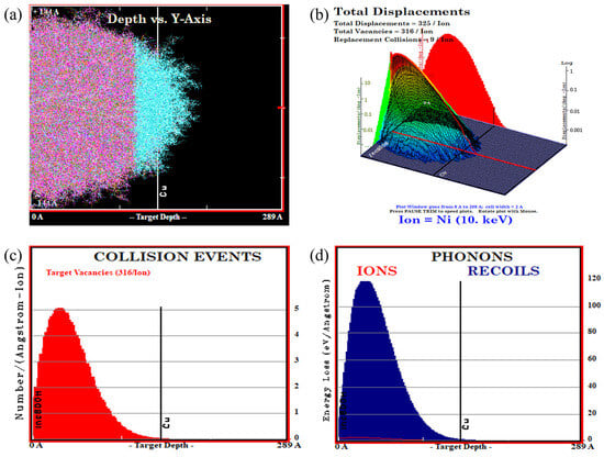
Figure 1.
SRIM calculation of damage in Inconel–Cu MMLC. (a) Target depth profile of Incoloy 800H–Cu MMLC, (b) 3-D log–log plot of the radiation displacement in Incoloy 800H–Cu, (c) damage vs. target depth plot, and (d) damage energy vs. target depth plot.
The value of the damage was obtained from the SRIM calculations, and fluence is the parameter that denotes the number of incident atoms per unit area of the interface. The displacement per atom (dpa) was calculated here [44] as
From the SRIM calculations, the value of dpa for one PKA was 2.24 × 10⁻³.
In our study, we neglected electronic stopping and assumed that the collision cascades are frictionless [56,57]. This assumption facilitates an inherent safety factor and leads to an overestimation of the damage. The modeling of electronic stopping can be performed by adding a friction term in the equation for the motion of atoms [58,59,60]. The NRT equation [54] is
where EPKA is the energy of the PKA and Ed is the threshold displacement energy.
The dpa value for one incident ion was calculated to be equal to 0.34 × 10⁻³ using the NRT equation. Compared with the dpa value calculated from the SRIM method, there was a drop of ~84% here. The SRIM’s internal model has significant error in calculating the number of vacancies [55]. Therefore, the NRT model, which uses the damage energy to calculate the number of displacements, was preferred in our work.
Nickel atoms are chosen to be the PKAs. There are 512,000 atoms in the simulation cell, thus, [44]. From the NRT model, without considering the phononic effect, to obtain a damage of 0.12 dpa for 10 keV, and using Ed = 23 eV for Ni [61], the number of PKAs is calculated as follows [54,55] to obtain a value of 354:
3. Results and Discussion
3.1. Defect Clustering
To obtain a robust statistical foundation, our MD simulations incorporated a minimum of three distinct seed velocities for each Inconel–Cu model, with an increase to four seed velocities for the Inconel 718–Cu model. In LAMMPS, the velocity of atoms is assigned during the initialization based on the simulation temperature, in a random fashion. To achieve different velocity distributions for a given temperature for statistical analysis, different numbers shall be selected as the seed of the random number generator for a given velocity distribution, which is called seed velocity. Here, we created a random seed number based on the atom’s xyz coordinates. Our results revealed that the introduction of a cascade via a PKA leads to the formation of Frenkel defect pairs, i.e., an equal number of vacancies and interstitials. Surprisingly, all Inconel–Cu models demonstrated a propensity for defect clustering, preferentially located along specific crystallographic planes within the copper and/or Inconel matrices after irradiation. These defect clusters manifested in three characteristic configurations shown in Figure 2 as follows: firstly, the clustering planes on both the Inconel and copper sides were oriented parallel to one another; secondly, these planes exhibited a mirrored arrangement; and thirdly, the planes were angularly disposed with respect to each other. Table 1 depicts the planes along which clustering, SF formation, and L-C lock formation happened in the different cases of each of the three models (video in Supplementary Materials). All the observed planes of defect clustering belonged to the {1 2 0} family of planes. The observed planes of SF formation and persistence, in the cases of Incoloy 800H–Cu and Inconel 718–Cu, belonged to the {1 2 2} family of planes, and these SF planes led to the formation of L-C locks in a couple of the cases of Incoloy 800H–Cu. When the SFs formed along the {1 2 0} family of planes, they were subsequently eliminated by the defect clustering process, which also happened along the same family of planes. These findings were corroborated through crystallographic analysis utilizing Crystal Maker version 11 [62]. Defect clustering was initiated only after the models underwent an irradiation damage value of ~0.045 dpa, i.e., after the incidence of ~120–130 PKAs. In the case of Incoloy 800H and Inconel 718, which had an atomic weight percentage of iron of 47% and 24%, respectively, defect clustering was observed at ~0.06 dpa damage. It occurred far more quickly in the case of Inconel 625, which had only 5% of iron in it.
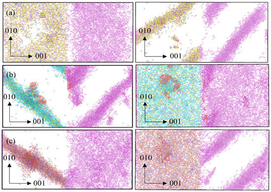
Figure 2.
Clustering planes in Inconel–Cu. (a) Front view and top view of clustering planes on the Inconel (left) and Cu (right) sides parallel to each other (in Incoloy 800H–Cu) at a dose of 0.119 dpa. (b) Front view and top view of clustering planes on the Inconel and Cu sides mirroring each other (in Inconel 718–Cu) at a dose of 0.091 dpa. (c) Front view and top view of clustering planes on the Inconel and Cu sides at an angle to each other (in Inconel 625–Cu) at a dose of 0.102 dpa. The visualization was performed using OVITO.

Table 1.
Defect clustering planes on the Inconel and Cu sides in the three models. The Inconel and Cu clustering planes were observed to belong to the {1 2 0} family of planes, while the SF and L-C locks formed along planes belonging to the {1 2 2} family of planes.
Irradiation-induced SFs [63] were observed on the Inconel interface. The formation of defect clusters created an elastic stress field, which led to the diminishing and subsequent elimination of these SFs and resulted in SF planes being replaced by defect cluster planes (Figure 3 and video in Supplementary Materials). The detection of these SFs can be made feasible through transmission electron microscopy [64]. In Incoloy 800H–Cu, the third seed velocity led to the formation of SFs, forming (L-C) locks [65]. The persistence of SFs and L-C locks prevented the defect clustering from occurring. In Inconel 718–Cu, the first seed velocity led to the clustering of SFs along a distinct plane. The SF and L-C lock planes belonged to the {1 2 2} family of planes (Figure 4). In Inconel 625–Cu, SFs could not cluster and were quickly eliminated by defect clustering. Incoloy 800H–Cu and Inc 718-Cu had much higher iron content in comparison with Inconel 625–Cu, which explains the formation of SFs and L-C locks in Inc 718-Cu and Inc 800H-Cu and why SFs could not cluster in Inc 625-Cu.
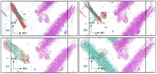
Figure 3.
Clustering of defects along the SF plane in an Inconel 718–Cu model. (a) The formation of the SF plane (the red layer) at a dose of 0.076 dpa. (b) The start of the formation of defect clusters at a dose of 0.086 dpa. (c) The diminishing of the SFs occurs because of the elastic stress field created by the defect clusters at a dose of 0.09 dpa. (d) Defect clusters after eliminating the SF plane at a dose of 0.091 dpa. The visualization was performed using OVITO.
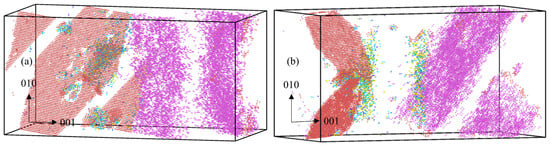
Figure 4.
Stacking faults in Inconel–Cu. (a) Three-dimensional view of the SF formation in the Inconel 718–Cu model at a dose of 0.083 dpa. The red layers denote the SF planes. (b) Three-dimensional view of two distinct SF planes (the red layers) forming an L-C lock in the Incoloy 800H–Cu model at a dose of 0.114 dpa. The pink layers denote the clustering of defects on the Cu side. The visualization was performed using OVITO.
The equilibrium distance between Fe and other alloying elements of Ni, Cr, and Cu is higher than bonds that do not involve Fe [51], leading to larger unit cells on average, which can accommodate interstitials during radiation without creating significant stresses. The higher the Fe content on the Inconel side, the higher this capability, and therefore, it delays the clustering of defects along a plane.
3.2. von Mises and Deviatoric Stresses
We investigated the influence of defect clustering on stress states by calculating hydrostatic, von Mises, and deviatoric stresses. Notably, deviatoric stress, characterized by three invariants, offers insights into shear stress magnitude and direction through its second (J2) and third (J3) invariants. Analyses of the hydrostatic stress revealed that all models exhibited compressive volume changes. Interestingly, in the analysis of von Mises stress, observations indicated a decrease in stress levels concomitant with the initiation of defect clustering on the Inconel side. Conversely, a pronounced increase in stress was noted with the onset of defect clustering on the Cu side, as shown in Figure 5a. These observations are parallel to the trends noted in J2, where the magnitude of shear stress increased sharply at points of copper clustering and decreased at points of Inconel clustering, as well as with the formation of SFs and L-C locks. The defect clustering configurations on the Cu and Inconel sides influence the direction of the shear stress, which was indicated as the third deviatoric stress invariant (J3). When the clustering planes on the Inconel side and the Cu side (i) were parallel to each other, the shear stress seemed to increase (J3 > 0); (ii) exhibited mirror symmetry, the shear stress seemed to increase (J3 > 0); and (iii) were at an angle to each other, the shear stress seemed to decrease (J3 < 0). The formation of SFs and L-C locks does not have a marked effect on the direction of shear stress.
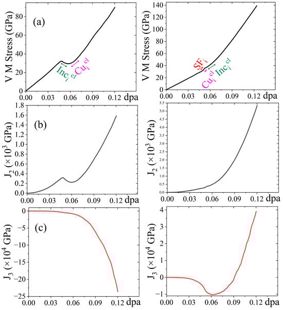
Figure 5.
Impact of stress on clustering. (a) von Mises stress vs. dpa plots, (b) second deviatoric stress invariant (J2) vs. dpa plots, and (c) third deviatoric stress invariant (J3) vs. dpa plots for two seed velocities of Incoloy 800H–Cu. Cuicl represents the copper clustering part, Incicl represents the Inconel clustering part, and SFi represents the SF formation part.
Another key finding was regarding the influence of clustering on the Inconel and Cu sides on the direction of the shear stress. Even though the ultimate direction of the shear stress was determined by the orientation of the defect clustering planes on the Inconel and Cu sides, we observed that there was a drop in the magnitude, or a tendency to have a dop in the magnitude, of the von Mises stress and the shear stress values whenever defect clustering happened on the Inconel side. On the Cu side, the von Mises and shear stress values saw a sharp rise in their magnitude whenever defect clustering happened there, as shown in Figure 5a,b.
Another indicator of the nature of the shear stress was the order in which defect clustering planes formed in the models. When Inconel clustering preceded clustering on the Cu side, the shear stress direction tended to veer towards being positive. When Inconel clustering followed clustering on the Cu side, the shear stress direction tended to edge towards the negative direction. However, the configuration of the defect clustering planes on the Inconel and Cu sides ultimately decided the nature of the shear stress.
The relaxation of the shear stress on the Inconel side drives the formation of defect clusters. Shear stress relaxation leads to the formation of SF planes, which are eliminated and replaced by defect clusters. The stress field on the Inconel side drives the defect clustering on the Cu side. Defect clustering may further lead to the formation of voids and microcracks upon agglomeration of the point defects unless they recombine with interstitials. Thus, defect clustering acts as a double-edged sword, which may make the MMLCs more structurally stable by relaxing the plastic deformation formed by SFs or may facilitate the failure of the MMLCs by initiating microcracks.
4. Conclusions
Three variants of Inconel–Cu alloys were exposed to irradiation employing PKAs with velocities equivalent to 10 keV energy, reaching a damage level of 0.12 dpa through MD simulations. The irradiation resulted in defect clustering, including vacancies and interstitials, predominantly observed along the {1 2 0} family of crystallographic planes on both the Inconel and Cu components. Specifically, on the Inconel side, defect clustering is facilitated by the annihilation of SFs. In cases where SFs were not eliminated, an aggregation of SFs alongside the formation of L-C locks was evident.
The propensity for SF accumulation was notably significant in Incoloy 800H–Cu, containing 47% iron, and Inconel 718–Cu, with 24% iron, while Inconel 625–Cu, with a mere 5% iron content, demonstrated the predominance of defect clustering over SF formation. This suggests a correlation between the iron content in Inconel alloys and the extent of defect clustering observed. Analysis of the von Mises stress revealed that clustering on the Cu side markedly increased the von Mises stress, while clustering on the Inconel side, SF, and L-C lock formations all led to a small drop in the von Mises stress.
The investigation into the shear stress dynamics, facilitated by plotting the second and third invariants of deviatoric stresses against dpa, showed that the nature of shear stress depends on the defect clustering configurations in the Inconel and Cu sides. Increasing shear stress was observed when defect clustering planes on the Inconel and Cu sides were parallel or mirrored, whereas decreasing shear stress manifested when these planes were angularly aligned. The comprehensive impact of defect clustering, including the effects of diffusion and defect quantity, warrants further investigation.
Supplementary Materials
The following supporting information can be downloaded at: https://www.mdpi.com/article/10.3390/jcs8040139/s1, Video S1: SF_formation; Video S2: SF_Elimination_by_defect_clustering.
Author Contributions
Conceptualization, resources, writing—review and editing, project administration, supervision, and funding acquisition, K.M.; writing—original draft preparation, methodology, formal analysis, and investigation, R.R. All authors have read and agreed to the published version of the manuscript.
Funding
This research was funded by DoE-ARPA-E OPEN (DE-AR0001066) and NSF-CAREER under NSF cooperative agreement CBET-2042683.
Data Availability Statement
Research data will be available upon request, considering copyright agreements applied to the data.
Acknowledgments
We would like to thank our colleagues, Nuruzzaman Sakib and Shiddartha Paul, for their help.
Conflicts of Interest
The authors declare no conflicts of interest.
References
- Murty, K.L.; Charit, I. Structural Materials for Gen-IV Nuclear Reactors: Challenges and Opportunities. J. Nucl. Mater. 2008, 383, 189–195. [Google Scholar] [CrossRef]
- Naebe, M.; Shirvanimoghaddam, K. Functionally Graded Materials: A Review of Fabrication and Properties. Appl. Mater. Today 2016, 5, 223–245. [Google Scholar] [CrossRef]
- Langevoort, J.C.; Sutherland, I.; Hanekamp, L.J.; Gellings, P.J. On the Oxide Formation on Stainless Steels AISI 304 and Incoloy 800H Investigated with XPS. Appl. Surf. Sci. 1987, 28, 167–179. [Google Scholar] [CrossRef]
- Thomas, A.; El-Wahabi, M.; Cabrera, J.M.; Prado, J.M. High Temperature Deformation of Inconel 718. J. Mater. Process. Technol. 2006, 177, 469–472. [Google Scholar] [CrossRef]
- Eiselstein, H.L.; Tillack, D.J. The Invention and Definition of Alloy 625. Superalloys 1991, 718, 1–14. [Google Scholar]
- Kumar, S.A.; Sathiya, P. Experimental Investigation of the A-TIG Welding Process of Incoloy 800H. Mater. Manuf. Process. 2015, 30, 1154–1159. [Google Scholar] [CrossRef]
- Ren, W.; Swindeman, R. Status of Alloy 800h in Considerations for the Gen IV Nuclear Energy Systems. J. Press. Vessel Technol. Trans. ASME 2014, 136, 054001. [Google Scholar] [CrossRef]
- Locatelli, G.; Mancini, M.; Todeschini, N. Generation IV Nuclear Reactors: Current Status and Future Prospects. Energy Policy 2013, 61, 1503–1520. [Google Scholar] [CrossRef]
- Hayner, G.O.; Corwin, W.R.; Bratton, R.L.; Burchell, T.D.; Wright, R.N.; Klett, J.W.; Windes, W.E.; Nanstad, R.K.; Totemeier, T.C.; Snead, L.L.; et al. Next Generation Nuclear Plant Materials Research and Development Program Plan; Idaho National Lab. (INL): Idaho Falls, ID, USA, 2005.
- Gan, J.; Cole, J.I.; Allen, T.R.; Shutthanandan, S.; Thevuthasan, S. Irradiated Microstructure of Alloy 800H. J. Nucl. Mater. 2006, 351, 223–227. [Google Scholar] [CrossRef]
- De Damborenea, J.; Lopez, V.; Vázquez, A.J. Improving High-Temperature Oxidation of Incoloy 800H by Laser Cladding. Surf. Coat. Technol. 1994, 70, 107–113. [Google Scholar] [CrossRef]
- Qi, H.; Azer, M.; Ritter, A. Studies of Standard Heat Treatment Effects on Microstructure and Mechanical Properties of Laser Net Shape Manufactured INCONEL 718. Metall. Mater. Trans. A Phys. Metall. Mater. Sci. 2009, 40, 2410–2422. [Google Scholar] [CrossRef]
- Kumar Krovvidi, S.C.S.P.; Padmakumar, G.; Bhaduri, A.K. Experience of Various Materials for Design and Manufacture of Bellows for Nuclear Industry. Adv. Mater. Proc. 2021, 2, 156–161. [Google Scholar] [CrossRef]
- Adiaconitei, A.; Vintila, I.S.; Mihalache, R.; Paraschiv, A.; Frigioescu, T.; Vladut, M.; Pambaguian, L. A Study on Using the Additive Manufacturing Process for the Development of a Closed Pump Impeller for Mechanically Pumped Fluid Loop Systems. Materials 2021, 14, 967. [Google Scholar] [CrossRef]
- Sotoodeh, K. Optimized Material Selection for Subsea Valves to Prevent Failure and Improve Reliability. Life Cycle Reliab. Saf. Eng. 2021, 10, 173–182. [Google Scholar] [CrossRef]
- Mathew, M.D.; Parameswaran, P.; Bhanu Sankara Rao, K. Microstructural Changes in Alloy 625 during High Temperature Creep. Mater. Charact. 2008, 59, 508–513. [Google Scholar] [CrossRef]
- Pearl, W.L.; Brush, E.G.; Gaul, G.G.; Leistikow, S. General Corrosion of Inconel Alloy 625® in Simulated Superheat Reactor Environment. Nucl. Appl. 2017, 3, 418–432. [Google Scholar] [CrossRef]
- Stevens, C.E.; Ross, R.W. Production, Fabrication, and Performance of Alloy 625 Clad Steel for Aggressive Corrosive Environments. J. Mater. Energy Syst. 1986, 8, 7–16. [Google Scholar] [CrossRef]
- Flanagan, C.A.; Brown, T.G.; Hamilton, W.R.; Lee, V.D.; Peng, Y.-K.M.; Shannon, T.E.; Spampinato, P.T.; Yugo, J.J.; Montgomery, D.B.; Bromberg, L.; et al. Overview of the Compact Ignition Tokamak. Fusion Technol. 1986, 10, 491–497. [Google Scholar] [CrossRef][Green Version]
- Miya, N.; Nagami, M.; Nakajima, S.; Nakamura, H.; Ushigusa, K.; Oikawa, A.; Nishitani, T.; Toyoshima, N.; Kinoshita, S.; Nakagawa, S.; et al. Conceptual Design Study of Nuclear Shielding for the Steady State Tokamak Device JT-60SU. Fusion Eng. Des. 1994, 23, 351–358. [Google Scholar] [CrossRef]
- Segantin, S.; Testoni, R.; Hartwig, Z.; Whyte, D.; Zucchetti, M. Exploration of a Fast Pathway to Nuclear Fusion: Thermal Analysis and Cooling Design Considerations for the ARC Reactor. Fusion Sci. Technol. 2020, 76, 45–52. [Google Scholar] [CrossRef]
- Moan, G.D.; Rudling, P. Zirconium in the Nuclear Industry: Thirteenth International Symposium; ASTM International: West Conshohocken, PA, USA, 2002; Volume 1423, ISBN 0803128959. [Google Scholar]
- Donaghy, R.E.; Sherman, A.H. Surface Coating Zr or Zr Alloy Nuclear Fuel Elements. GB Patent Document 2024262/A/, 1980. Available online: http://inis.iaea.org/search/search.aspx?orig_q=RN:11527424 (accessed on 2 April 2024).
- Bandriyana, B.; Prajitno, D.H.; Dimyati, A. Effect of Copper Addition on High Temperature Oxidation of Zirconium Alloy ZrNbMoGe for Advanced Reactor Fuel Cladding Material. Adv. Mater. Res. 2014, 896, 617–620. [Google Scholar] [CrossRef]
- Xu, L.; Xiao, Y.; van Sandwijk, A.; Xu, Q.; Yang, Y. Production of Nuclear Grade Zirconium: A Review. J. Nucl. Mater. 2015, 466, 21–28. [Google Scholar] [CrossRef]
- Smith, H.D. The Influence of Copper on Zircaloy Spent Fuel Cladding Degradation under a Potential Tuff Repository Condition; No. UCRL-15993; HEDL-SA-3583; CONF-870306-71; Nevada Nuclear Waste Storage Investigations Projects Dept.; Sandia National Labs.: Albuquerque, NM, USA, 1987.
- Hong, H.S.; Kim, H.S.; Kim, S.J.; Lee, K.S. Effects of Copper Addition on the Tensile Properties and Microstructures of Modified Zircaloy-4. J. Nucl. Mater. 2000, 280, 230–234. [Google Scholar] [CrossRef]
- Wan, Y.; Wang, X.; Sun, H.; Li, Y.; Zhang, K.; Wu, Y. Corrosion Behavior of Copper at Elevated Temperature. Int. J. Electrochem. Sci. 2012, 7, 7902–7914. [Google Scholar] [CrossRef]
- Kong, D.C.; Dong, C.F.; Xiao, K.; Li, X.G. Effect of Temperature on Copper Corrosion in High-Level Nuclear Waste Environment. Trans. Nonferrous Met. Soc. China (Engl. Ed.) 2017, 27, 1431–1438. [Google Scholar] [CrossRef]
- Chung, D.D.L. Materials for Thermal Conduction. Appl. Therm. Eng. 2001, 21, 1593–1605. [Google Scholar] [CrossRef]
- Bahgat, A.; El-Meniawi, M.A.H.; Khafagy, S.M.; Sallam, H.E.-D.M.; Atta, M. Effect of Mold Casting Parameters in Interface Properties of Iron/Copper Bimetallic Composites Based upon an Ancient Quranic Metal Matrix Composite (QMMC). Int. J. Met. 2024, 18, 821–834. [Google Scholar] [CrossRef]
- Pan, T.; Zhang, X.; Yamazaki, T.; Sutton, A.; Cui, W.; Li, L.; Liou, F. Characteristics of Inconel 625—Copper Bimetallic Structure Fabricated by Directed Energy Deposition. Int. J. Adv. Manuf. Technol. 2020, 109, 1261–1274. [Google Scholar] [CrossRef]
- Onuike, B.; Heer, B.; Bandyopadhyay, A. Additive Manufacturing of Inconel 718—Copper Alloy Bimetallic Structure Using Laser Engineered Net Shaping (LENSTM). Addit. Manuf. 2018, 21, 133–140. [Google Scholar]
- Allen, T.; Busby, J.; Meyer, M.; Petti, D. Materials Challenges for Nuclear Systems. Mater. Today 2010, 13, 14–23. [Google Scholar] [CrossRef]
- Holt, R.A. Mechanisms of Irradiation Growth of Alpha-Zirconium Alloys. J. Nucl. Mater. 1988, 159, 310–338. [Google Scholar] [CrossRef]
- Winter, I.S.; Rudd, R.E.; Oppelstrup, T.; Frolov, T. Nucleation of Grain Boundary Phases. Phys. Rev. Lett. 2022, 128, 035701. [Google Scholar] [CrossRef]
- Chen, P.; Chesetti, A.; Demkowicz, M.J. Healing of Nanocracks by Collision Cascades in Nickel. J. Nucl. Mater. 2021, 555, 153124. [Google Scholar] [CrossRef]
- Seitz, F. On the Theory of Diffusion in Metals. Acta Crystallogr. 1950, 3, 355–363. [Google Scholar] [CrossRef]
- Jin, M.; Cao, P.; Short, M.P. Mechanisms of Grain Boundary Migration and Growth in Nanocrystalline Metals under Irradiation. Scr. Mater. 2019, 163, 66–70. [Google Scholar] [CrossRef]
- Plimpton, S. Fast Parallel Algorithms for Short-Range Molecular Dynamics. J. Comput. Phys. 1995, 117, 1–19. [Google Scholar] [CrossRef]
- Jiang, D.; Zhang, D.; Li, X.; Wang, S.; Wang, C.; Qin, H.; Guo, Y.; Tian, W.; Su, G.H.; Qiu, S. Fluoride-Salt-Cooled High-Temperature Reactors: Review of Historical Milestones, Research Status, Challenges, and Outlook. Renew. Sustain. Energy Rev. 2022, 161, 112345. [Google Scholar] [CrossRef]
- Zou, P.F.; Bader, R.F.W. A Topological Definition of a Wigner–Seitz Cell and the Atomic Scattering Factor. Acta Crystallogr. A 1994, 50, 714–725. [Google Scholar] [CrossRef]
- Stukowski, A. Visualization and Analysis of Atomistic Simulation Data with OVITO—The Open Visualization Tool. Model. Simul. Mater. Sci. Eng. 2009, 18, 015012. [Google Scholar] [CrossRef]
- Paul, S.; Schwen, D.; Short, M.P.; Momeni, K. Effect of Irradiation on Ni-Inconel/Incoloy Heterostructures in Multimetallic Layered Composites. J. Nucl. Mater. 2021, 547, 152778. [Google Scholar] [CrossRef]
- Paul, S.; Schwen, D.; Short, M.P.; Erickson, A.; Momeni, K. Effect of Differently Oriented Interlayer Phases on the Radiation Damage of Inconel-Ni Multimetallic Layered Composite. J. Alloys Compd. 2022, 915, 165432. [Google Scholar] [CrossRef]
- Paul, S.; Schwen, D.; Short, M.P.; Momeni, K. A Modified Embedded-Atom Method Potential for a Quaternary Fe-Cr-Si-Mo Solid Solution Alloy. Materials 2023, 16, 2825. [Google Scholar] [CrossRef]
- Paul, S.; Muralles, M.; Schwen, D.; Short, M.; Momeni, K. A Modified Embedded-Atom Potential for Fe-Cr-Si Alloys. J. Phys. Chem. C 2021, 125, 22863–22871. [Google Scholar] [CrossRef]
- Paul, S.; Momeni, K.; Schwen, D.; Short, M.P. Radiation Damage Study of T91/Fe-Cr-Si Multimetallic Layered Composite for Generation IV Reactor Deployment. In Proceedings of the Energy Proceedings, Cambridge, CA, USA; Scanditale AB: Stockholm, Sweden, 2021; pp. 11–13. [Google Scholar]
- Nordlund, K.; Ghaly, M.; Averback, R.S.; Caturla, M.; de La Rubia, T.D.; Tarus, J. Defect Production in Collision Cascades in Elemental Semiconductors and Fcc Metals. Phys. Rev. B 1998, 57, 7556. [Google Scholar] [CrossRef]
- Was, G.S. Fundamentals of Radiation Materials Science: Metals and Alloys; Springer: Berlin/Heidelberg, Germany, 2016; ISBN 1493934384. [Google Scholar]
- Farkas, D.; Caro, A. Model Interatomic Potentials and Lattice Strain in a High-Entropy Alloy. J. Mater. Res. 2018, 33, 3218–3225. [Google Scholar] [CrossRef]
- Ziegler, J.F.; Ziegler, M.D.; Biersack, J.P. SRIM—The Stopping and Range of Ions in Matter (2010). Nucl. Instrum. Methods Phys. Res. B 2010, 268, 1818–1823. [Google Scholar] [CrossRef]
- Ziegler, J.F.; Biersack, J.P. The Stopping and Range of Ions in Matter. In Treatise on Heavy-Ion Science; Springer: Boston, MA, USA, 1985; pp. 93–129. [Google Scholar] [CrossRef]
- Norgett, M.J.; Robinson, M.T.; Torrens, I.M. A Proposed Method of Calculating Displacement Dose Rates. Nucl. Eng. Des. 1975, 33, 50–54. [Google Scholar] [CrossRef]
- Stoller, R.E.; Toloczko, M.B.; Was, G.S.; Certain, A.G.; Dwaraknath, S.; Garner, F.A. On the Use of SRIM for Computing Radiation Damage Exposure. Nucl. Instrum. Methods Phys. Res. B 2013, 310, 75–80. [Google Scholar] [CrossRef]
- Zarkadoula, E.; Duffy, D.M.; Nordlund, K.; Seaton, M.A.; Todorov, I.T.; Weber, W.J.; Trachenko, K. Electronic Effects in High-Energy Radiation Damage in Tungsten. J. Phys. Condens. Matter 2015, 27, 135401. [Google Scholar] [CrossRef] [PubMed]
- Zarkadoula, E.; Daraszewicz, S.L.; Duffy, D.M.; Seaton, M.A.; Todorov, I.T.; Nordlund, K.; Dove, M.T.; Trachenko, K. Electronic Effects in High-Energy Radiation Damage in Iron. J. Phys. Condens. Matter 2014, 26, 085401. [Google Scholar] [CrossRef] [PubMed]
- Zarkadoula, E.; Samolyuk, G.; Xue, H.; Bei, H.; Weber, W.J. Effects of Two-Temperature Model on Cascade Evolution in Ni and NiFe. Scr. Mater. 2016, 124, 6–10. [Google Scholar] [CrossRef]
- Zarkadoula, E.; Samolyuk, G.; Zhang, Y.; Weber, W.J. Electronic Stopping in Molecular Dynamics Simulations of Cascades in 3C–SiC. J. Nucl. Mater. 2020, 540, 152371. [Google Scholar] [CrossRef]
- Zarkadoula, E.; Samolyuk, G.; Weber, W.J. Two-Temperature Model in Molecular Dynamics Simulations of Cascades in Ni-Based Alloys. J. Alloys Compd. 2017, 700, 106–112. [Google Scholar] [CrossRef]
- Kenik, E.A.; Mitchell, T.E. Orientation Dependence of the Threshold Displacement Energy in Copper and Vanadium. Philos. Mag. J. Theor. Exp. Appl. Phys. 1975, 32, 815–831. [Google Scholar] [CrossRef]
- Kohn, S.C. CrystalMaker: Interactive Crystallography. Terra Nova 1995, 7, 554–556. [Google Scholar] [CrossRef]
- Schäublin, R.; Yao, Z.; Baluc, N.; Victoria, M. Irradiation-Induced Stacking Fault Tetrahedra in Fcc Metals. Philos. Mag. 2005, 85, 769–777. [Google Scholar] [CrossRef]
- Li, B.; Yan, P.F.; Sui, M.L.; Ma, E. Transmission Electron Microscopy Study of Stacking Faults and Their Interaction with Pyramidal Dislocations in Deformed Mg. Acta Mater. 2010, 58, 173–179. [Google Scholar] [CrossRef]
- Yan, Z.; Lin, Y. Lomer-Cottrell Locks with Multiple Stair-Rod Dislocations in a Nanostructured Al Alloy Processed by Severe Plastic Deformation. Mater. Sci. Eng. A 2019, 747, 177–184. [Google Scholar] [CrossRef]


Disclaimer/Publisher’s Note: The statements, opinions and data contained in all publications are solely those of the individual author(s) and contributor(s) and not of MDPI and/or the editor(s). MDPI and/or the editor(s) disclaim responsibility for any injury to people or property resulting from any ideas, methods, instructions or products referred to in the content. |
© 2024 by the authors. Licensee MDPI, Basel, Switzerland. This article is an open access article distributed under the terms and conditions of the Creative Commons Attribution (CC BY) license (https://creativecommons.org/licenses/by/4.0/).