Article

Bio-Inspired Helicoidal Composite Structure Featuring Graded Variable Ply Pitch under Transverse Tensile Loading

by
Hossein Malekinejad
1,
Ricardo J. C. Carbas
1,2,*,
Alireza Akhavan-Safar
1,*,
Eduardo A. S. Marques
2,
Maria Ferreira
1 and
Lucas F. M. da Silva
2
1
Instituto de Ciência e Inovação em Engenharia Mecânica e Engenharia Industrial (INEGI), Rua Dr. Roberto Frias, 4200-465 Porto, Portugal
2
Departamento de Engenharia Mecânica, Faculdade de Engenharia (FEUP), Universidade do Porto, Rua Dr. Roberto Frias, 4200-465 Porto, Portugal
*
Authors to whom correspondence should be addressed.
J. Compos. Sci. 2024, 8(6), 228; https://doi.org/10.3390/jcs8060228
Submission received: 28 February 2024 / Revised: 15 May 2024 / Accepted: 13 June 2024 / Published: 16 June 2024
(This article belongs to the Special Issue Sustainable Biocomposites, Volume II)

Abstract

:
Biostructures found in nature exhibit remarkable strength, toughness, and damage resistance, achieved over millions of years. Observing nature closely might help develop laminates that resemble natural structures more closely, potentially improving strength and mimicking natural principles. Bio-inspired Carbon Fiber-Reinforced Polymers (CFRP) investigated thus far exhibit consistent pitch angles between layers, whereas natural structures display gradual variations in pitch angle rather than consistency. Therefore, this study explores helicoidal CFRP laminates, focusing on the Non-Linear Rotation Angle (NLRA) or gradual variation to enhance composite material performance. In addition, it compares the strength and failure mechanisms of the gradual configuration with conventional helicoidal and unidirectional (UD) laminates, serving as references while conducting transverse tensile tests (out-of-plane tensile). The findings highlight the potential of conventional and gradual helicoidal structures in reinforcing CFRP laminates, increasing the failure load compared to unidirectional CFRP laminate by about 5% and 17%, respectively. In addition, utilizing bio-inspired configurations has shown promising improvements in toughness compared to traditional unidirectional laminates, as evidenced by the increased displacement at failure. The numerical and experimental analyses revealed a shift in crack path when utilizing the bio-inspired helicoidal stacking sequence. Validated by experimental data, this alteration demonstrates longer and more intricate crack propagation, ultimately leading to increased transverse strength.

1. Introduction

Composite materials consist of fibers that offer strength, combined with a supporting matrix to maintain structural integrity and withstand shear stress. This combination forms a robust material with properties superior to its individual components [1,2]. The use of composite laminates is increasing due to its high specific strength and outstanding performance under various loading conditions [3,4,5]. However, the weaknesses and disadvantages of composite laminates under out-of-plane loading and resulting failure modes including delamination and matrix cracking should be addressed [6,7,8].
In composite laminates loads directed perpendicular to the fiber’s orientation must be carried by the matrix, which consistently exhibits weaker strength compared to the fiber [9]. Addressing this challenge, several concepts have been presented in the literature over the years to enhance the out-of-plane strength of composite laminates. Altering the stacking sequence and using multidirectional (MD) CFRP [10,11], strengthening individual components [12,13] and employing thinplies [9,14] stand among various solutions proposed to deal with this issue. In the context of altering the stacking sequence, which aim to replicate forms, functions, and principles from the natural world, have led to the creation of lightweight, stronger composite materials capable of withstanding damage. Numerous intricate biological structures in nature, like nacre [15] and the dactyl club of the mantis shrimp [16], prove to be sources of inspiration for bio-inspired structures that offer increased strength and also toughness. Researchers discovered that mantis shrimp clubs possess an inner structure arrangement resembling a spiral, called a helicoidal structure (see Figure 1) [17,18,19,20]. This unique arrangement, artificially achieved by stacking and rotating adjacent fiber layers in helicoidal manner, enable it to have remarkable toughness and strength, and effectively dissipate energy compared to conventional structures [10,21]. Using the aforementioned bio-inspired structure, Grunenfelder et al. [22] manufactured CFRP to achieve high-performance laminates. They concluded that the propagation of damage decreased in helicoidal laminates compared to conventional unidirectional (UD) and cross-ply laminates under impact loading. It has been concluded that the bio-inspired helicoidal configuration holds more promise than traditional cross-ply configurations for investigation. Other studies have reached similar conclusions, further emphasizing the importance of focusing on helicoidal laminates and clarifying their advantages and challenges. Similarly, Cheng et al. [23] presented substantial enhancements in the mechanical performance of the bio-inspired helicoidal laminate, particularly for smaller fiber rotations, surpassing that of the traditional composite laminate. It is generally accepted that the bio-inspired helicoidal laminate redirects intralaminar failures (matrix cracking) by adjusting the angle between each layer, leading to a more complex crack path [24]. Moreover, helicoidal laminates are prone to resistance against interlaminar (delamination) failure, which is known as the cause of catastrophic failure in composite materials [25]. Once delamination becomes the predominant mode of failure, surpassing matrix cracking, it poses a substantial risk of degrading the properties of laminates, potentially leading to catastrophic failures in composite laminates and components over their service life [26,27]. This phenomenon occurs because matrix cracking is recognized as a less-severe form of failure compared to delamination [8]. In essence, delamination can severely compromise the integrity of the entire laminate, resulting in more catastrophic failure. However, helicoidal structures are still susceptible to various intricate damage mechanisms, such as fiber breakage, matrix cracking, fiber/matrix interface separation, and delamination [28,29].
According to the reviewed research and literature, variations in ply orientation significantly impact the strength and toughness of composite laminate structures by changing damage mechanisms or the crack path. Shang et al. [30] conducted experimental and numerical assessments of helicoidal laminates under transverse point loading. They compare the helicoidal stacking sequence with traditional cross-ply laminates and also consider two different pitch angles in helicoidal laminates. Their findings indicated that the helicoidal laminate with a helicoid angle of 10° exhibited improved peak load and stiffness, while also showing reduced occurrences of fiber failure and delamination compared to a similar laminate in terms of the number of layers with a cross-ply layup. As a result, bio-inspired laminates can achieve higher strength if their pitch angles are properly designed to closely mimic nature. The more closely the laminates mimic nature, the higher strength can be achieved.
As we explore the intricate structures found in nature that serve as inspiration for CFRP laminates, particular attention is directed to nonlinear variations in the angles between adjacent layers, as illustrated in Figure 1. This unique design involves a gradual rotation of layers, commencing with smaller angles and progressively increasing to higher ones. Another noteworthy aspect observed in natural structures is the presence of distinct blocks of rotated fibers, a pattern that repeats after completing a full rotation period. This deliberate arrangement contributes to the complexity and strength inherent in these bio-inspired composite structures. However, replicating natural structures presents difficulties in achieving extremely low-angle pitches and ensuring a restricted number of repetitions of the bio-inspired unit throughout the thickness to attain the desired overall thickness.
Due to the manufacturing challenges associated with bio-inspired helicoidal laminates featuring small pitch angles, there is limited literature focusing on taking advantage of these smaller angles or incorporating a gradual change in pitch angle starting from a smaller angle and increasing through the thickness [17,31]. Furthermore, these studies rarely exceed two repetitions of the bio-inspired distinct blocks throughout the thickness [22]. In this context, Jiang et al. [24] developed laminates with helicoidal layups inspired by Non-Linear Rotation Angle (NLRA) from nature to enhance the impact resistance of composite laminates. They utilized a numerical progressive damage model to study the failure behavior of bio-inspired CFRP laminates, validating their model through experimental tests. Their findings suggested that compared to Quasi-isotropic (QI) stacking sequence, laminates with significant rotation angles notably enhance impact resistance. Michele Meo et al. [32] similarly designed bio-inspired helicoidal laminates with functionally graded pitch (FGP) to enhance impact resistance. Unlike traditional laminates, FGP mimics natural structures with varying pitch rotation, optimizing energy absorption. Their results showed a 41% reduction in damaged area, 111% increase in post-impact energy, and notable improvements in mechanical strength and elastic energy capacity compared to benchmarks.
Therefore, in this study, to mimic nature more accurately, CFRP laminates were created with a gradual change in the angle of each layer. This gradual alteration in rotation angle has been neglected in many studies exploring bio-inspired helicoidal CFRP laminates. To closely replicate the dactyl club’s structure within the constraints of manufacturing, as outlined in Section 2.1, this study produced and tested gradual helicoidal CFRP with four blocks of rotated layers throughout the thickness. Additionally, unidirectional and conventional helicoidal laminates were manufactured and used as benchmarks.
Nevertheless, to the best of the authors’ knowledge, prior studies have predominantly emphasized the advantages of helicoidal laminates in impact and compression, with limited exploration into their bending behavior and an absence of consideration for their out-of-plane tensile performance. Hence, in this study, the UD laminates served as the baseline; and two helicoidal laminates one with a constant pitch angle of 20° and the other with NLRA or gradual pitch angle were manufactured and tested under transverse tensile loading. The strength of the mentioned laminates and failure mechanisms using optical microscopic pictures, were evaluated experimentally. Additionally, the failure mechanism and the effect of stacking sequence on the stress distribution of CFRP laminates were studied numerically.
Figure 1. (a) Mantis shrimp; (b) Dactyl club; (c) Schematic illustrating the helicoidal structure, providing clarity on the origins of the aligned fiber layers’ helicoidal arrangement; (d) SEM image depicting a fracture surface, unveiling a fibrous arrangement organized in a helicoidal pattern. (Adapted from [16,33]).
Jcs 08 00228 g001

2. Experimental Study

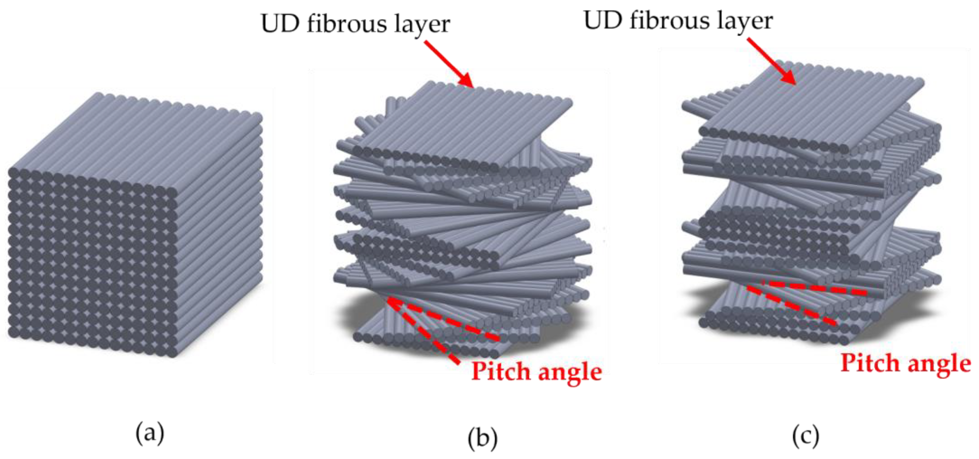
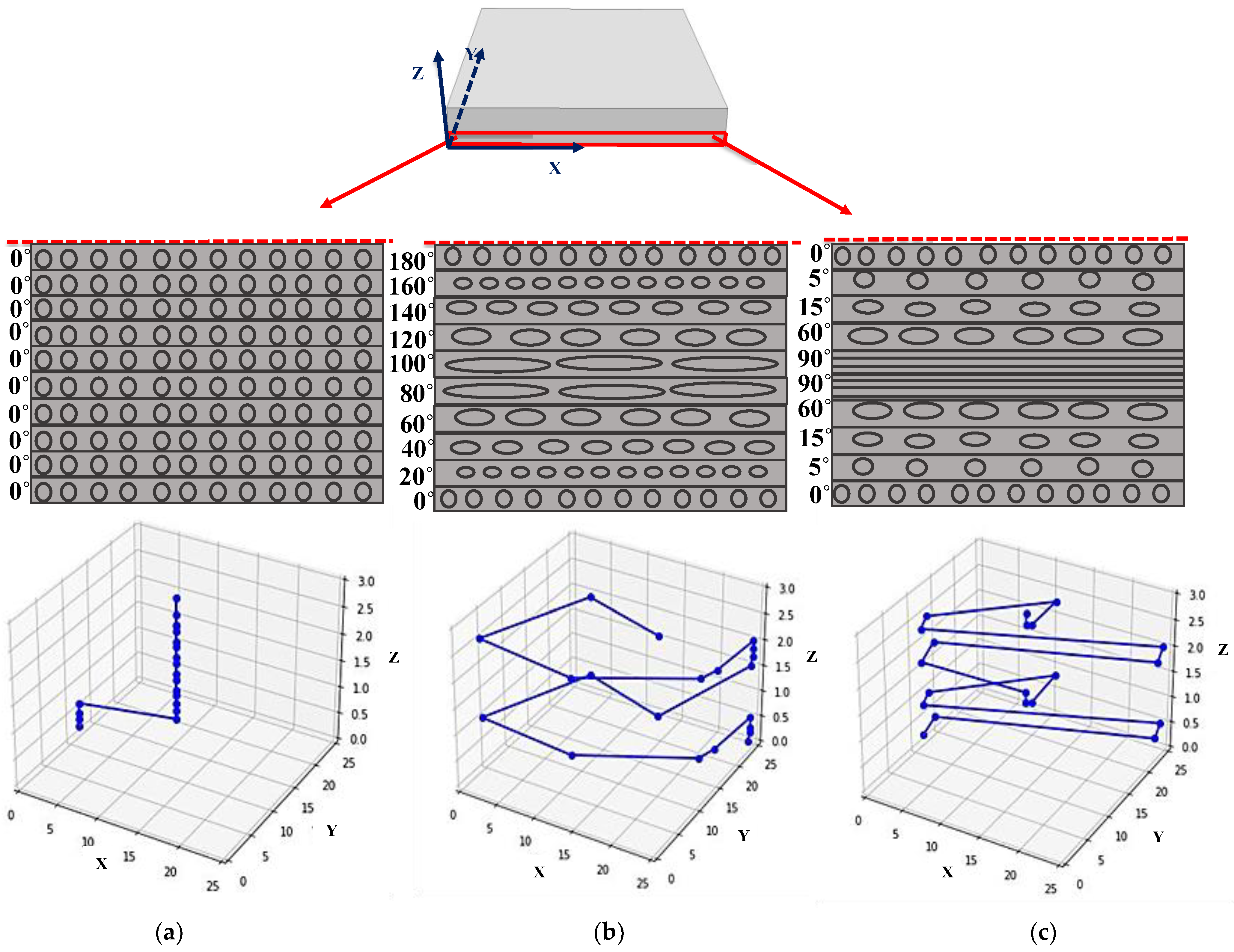
2.1. Bio-Inspired Helicoidal Laminates Manufacturing Limitation

Nature exhibits anti-symmetrical stacking sequences that lead to a couple between in-plane and out-of-plane behaviors in structures [34]. Therefore, mimicking this natural structure synthetically using conventional composite materials may result in warping due to residual stresses from the curing process. This warping is influenced by properties of the laminate, including stiffness, thermal expansion coefficient, Poisson’s ratio, and the sequence in which layers are stacked [35]. Moreover, the asymmetrical structure of conventional composites can result in unpredictable stress concentration because of the unbalanced distribution of stress, making the integrity and stability of the structure undesirable. Therefore, while bio-inspired composites hold promise, their asymmetry restricts their practical application. However, in nature, such concerns are irrelevant since manufacturing takes place under ambient conditions.
Emphasizing mid-plane symmetry simplifies the manufacturing process for helicoidal laminates and eliminates the warping effect that occurs during the curing process. To understand how warping can occur due to the curing process, taking into account the classical laminate theory might be beneficial. This theory is accessible in many references and is presented here briefly based on Reddy’s book [5,23]. The bending–extension coupling stiffnesses can be defined as Equation (1):
Bij = k = 1 N ( Q ¯ i j ) k ( h k 2 h k 1 2 )   i , j = 1,2 , 6
in which Q ¯ is the transfer matrix for representing the elastic properties of the laminate with different orientations in accordance with the global coordination system. N represents the number of laminas, where hk stands for the distance from the mid-surface to the upper side of the kth layer, and hk−1 denotes the distance to the lower side of the kth layer. If mid-plane symmetry is not established, a non-zero value for Bij results; hence, warping occurs during the curing process.
Another challenge in mimicking nature is the difficulty in obtaining the right small pitch angle for producing synthetical helicoidal laminates. It is important to highlight that selecting a particular pitch angle can impact the symmetry and the number of layers needed to maintain a constant thickness. Additionally, it has an effect on the response of laminate under different loading and deformation conditions; for instance, if 20 plies with a pitch angle of 5° is considered, the plies in the stack would rotate from 0° to only 95°. Each ply is rotated by 5° relative to the previous one, resulting in an unsymmetrical rotation throughout the thickness which in turn would lead to certain generally undesired effects which are addressed later on in this section. To attain symmetry and balance in the helicoidal laminate, researchers incorporated multiple extra mid-plane layers into the laminate sequence [25]. Typically, a higher total number of layers provides designers with increased flexibility in selecting the pitch angle and, consequently, the lamination scheme.
Due to the explained limitations in manufacturing CFRP laminates to prevent warping and the gradual development of angles throughout the thickness in bio-inspired laminates, achieving a complete mimicry of nature has proven challenging and impractical. To closely replicate the natural structure with the required thickness, a gradual design ([0/5/15/60/90/90/60/15/5/0]s) was implemented and manufactured alongside a conventional helicoidal laminate, altering the angle between each layer by 20 degrees ([0/20/40/60/80/100/120/140/160/180]s) (see Figure 2). Furthermore, a benchmark specimen was fabricated, comprising unidirectional plies with a total of twenty layers.
Consequently, in addition to considering bio-inspired mimicry, the unsymmetrical problem was taken into account, and two variations were designed (Table 1 and Figure 2), as described in the following section. Both designs intend to solve the unsymmetrical problem by enforcing a mid-plane symmetry while maintaining the gradual ply rotation pattern in the laminate stacking sequence. The resulting laminates remained flat after manufacturing.

2.2. Laminate Manufacturing
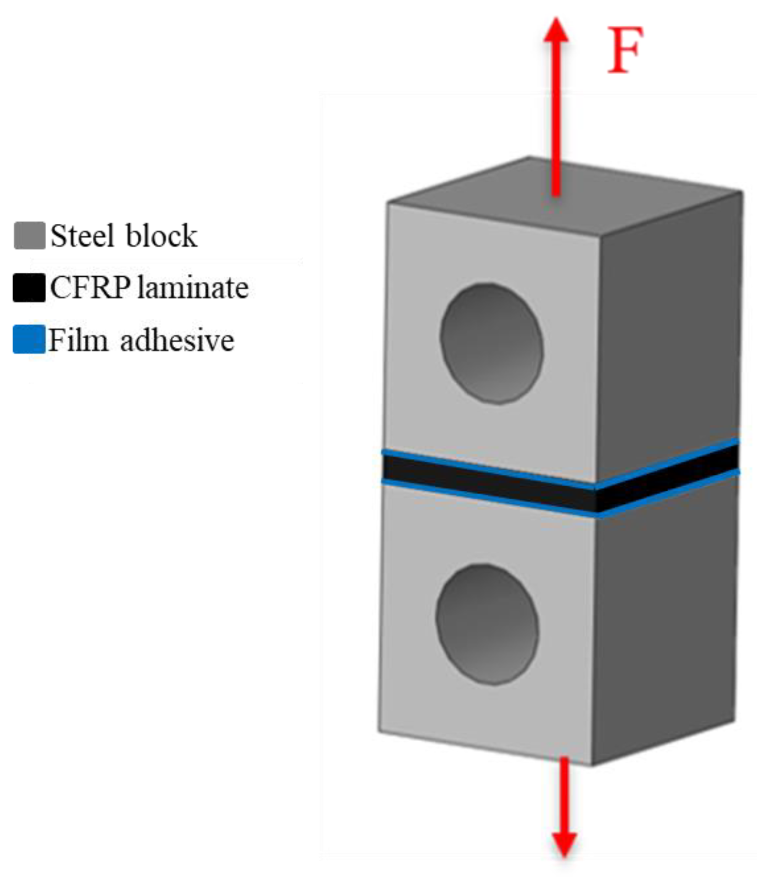
All laminates manufactured in this study utilized unidirectional carbon–epoxy prepreg with a ply thickness of 0.15 mm from the same batch, supplied by Seal Spa of Italy, known commercially as Texipreg HS160T700. Three distinct stacking sequences were fabricated: unidirectional, conventional helicoidal, and gradual helicoidal laminates, as outlined in Table 1 and Figure 2.
All laminates were manufactured using the hand layup method, beginning with a layer-by-layer stacking of the plies and adjusting the angle between each layer according to the designated sequences.
The stacking of the plies layer by layer persists until the desired thickness is attained. To guarantee that all the produced laminates have a consistent thickness of 3 mm, an aluminum mold was employed. Consequently, all configurations maintained a consistent thickness of 3 mm, comprising a total of 20 plies and exhibiting symmetry with respect to the midplane. A release agent was applied to the surface of the mold to make it easier to remove the laminate after curing. Subsequently, the plates were subjected to curing in a hot press at the conditions advised by the manufacturer: 30 bar pressure and a temperature of 130 °C for a duration of 2 h [9]. Following the curing process, the plates were trimmed to achieve the specified desired dimensions of 25 × 25 mm2. Finally, the cured laminates were attached to the steel block, allowing for a transverse tensile load to be applied (see Figure 3). The attachment process included the use of a film adhesive commercially known as Scotch Weld AF 163-2k (3M, Saint Paul, MN, USA). For achieving optimal adhesion of laminates and steel blocks, it is essential to employ distinct surface preparation methods; one for the composite laminate and another for the steel surfaces. The steel surface was first subjected to sanding using a sanding machine, followed by a thorough cleaning with acetone to eliminate any contaminants.
Regarding the composite laminate, initially, the composite laminates’ surfaces underwent preparation involving light sanding using sandpaper and subsequent cleansing with acetone to eliminate any contaminants. Following this, a plasma treatment was conducted on the composite surfaces to enhance their surface energy before the bonding process. Finally, curing required keeping the assembly at room temperature for 24 h under pressure according to the supplier recommendations. Following the curing process, the film adhesive was manually cleaned using sandpaper, ensuring the laminate remained undamaged.

2.3. Testing Method

Five samples for each configuration were manufactured and underwent transverse tensile testing using an Instron machine capacity of 30 kN, subjected to a consistent speed of 1 mm/min (quasi-static) to guarantee test repeatability. The tests were carried out under ambient conditions (room temperature of 24 °C and a relative humidity of 55%). The repeatability of the results was ensured by subjecting a minimum of five specimens to the transverse tensile test. It should be noted that no specific standard was adhered to for these tests; however, the test conditions remained constant for all configurations, ensuring the comparability of the results.

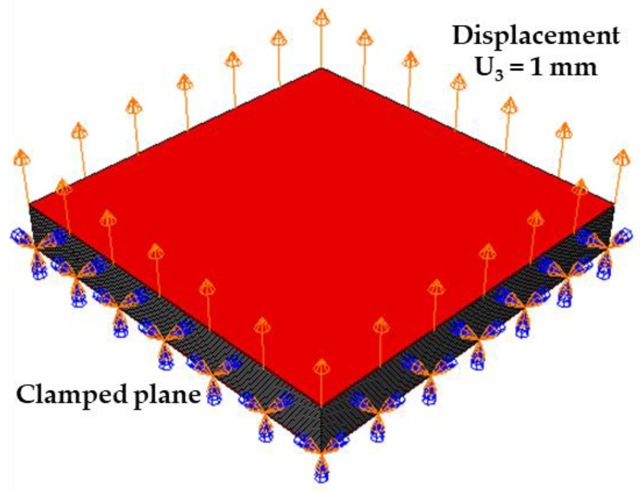
2.4. Numerical Study

Three distinct static linear models were developed in the Abaqus software, each corresponding to a specific configuration: conventional helicoidal, gradual helicoidal, and unidirectional. The models replicated the experiment conditions concerning geometry, loading, and boundary conditions. A composite model comprises 20 distinct plies, with each layer assigned specific angles based on the manufacturing configuration. Two layers, each with a thickness of 0.1 mm, were simulated to replicate the elastic properties of the film adhesive (utilized for bonding the laminate to steel blocks). The film adhesive mentioned was characterized in a prior study [36]. Tests were performed on bulk samples, revealing a Young’s modulus of 1.52 GPa and a Poisson’s ratio of 0.35. The material properties assigned to each lamina can be found in Table 2.
The eight-node linear brick elements (C3D8R) were employed, and a mesh convergence analysis was carried out to verify the model’s accurate elastic response during transverse tensile tests. A study on mesh convergence was performed to confirm the model’s accuracy in elastic response and the consistency of results regardless of the mesh used. For this purpose, the distribution of von Mises stress was analyzed to ascertain the minimum appropriate element size, and the mesh of the model converged at a minimum size of 0.09 mm. A vertical transverse tensile displacement equal to 1 mm was applied to the outer surface of the film adhesive. The boundary conditions and displacement applied is shown in Figure 4.

3. Results and Discussion

3.1. Numerical Results

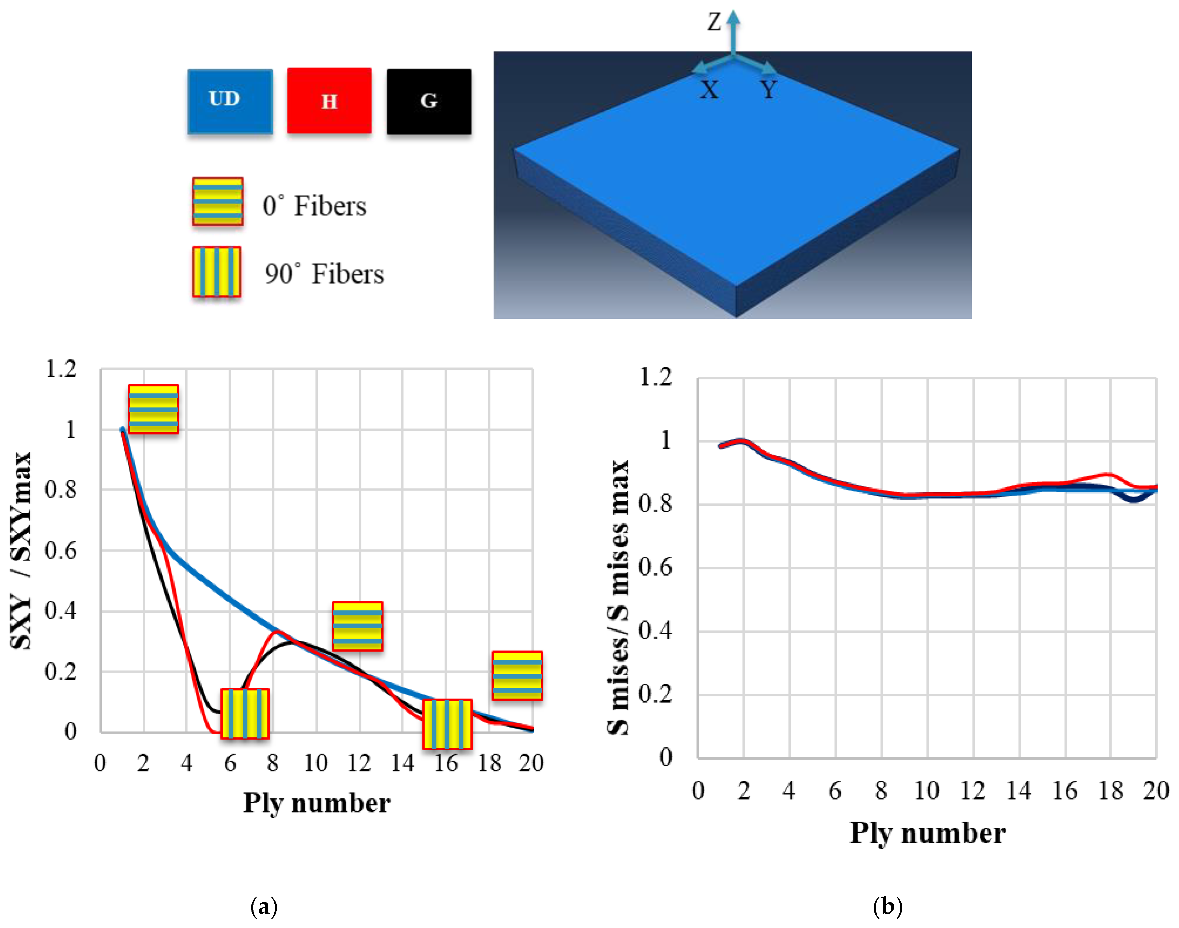
3.1.1. Influence of Laminate Thickness on Stress Distribution

Accurately determining the out-of-plane tensile strength in CFRP laminates is considered to be of significance in designing these materials, particularly for thinner laminates subjected to multidirectional loading conditions [38]. However, in the context of a laminate subjected to transverse tensile tests, the stress distribution is impacted by both the laminate’s thickness and the adhesive employed for bonding the laminate to steel blocks. In this research, as elaborated in Section 2.2, we utilized a toughened film adhesive to diminish the impact of the adhesive applied between the steel block and laminates on the stress distribution of laminates. Another aspect assessed was the influence of laminate thickness on the stress concentration. Localized stress concentration arises due to the non-uniform stress distribution in transverse tensile loading, and the failure load is affected by the locus in which stress concentration is raised. As a result, to make the investigation of transverse tensile strength independent of laminate thickness and stress concentration, a numerical study was conducted. Figure 5 shows the stress ratio σZ, determined by dividing the maximum stress in direction Z, based on the displayed coordination system, by the mean stress in the unidirectional laminate configuration numerically. As depicted in Figure 5, the stress is relaxed and the stress concentration decreases when the thickness is reduced to 3.5 mm or less (distinguished with a red circle). Based on this conclusion, it was confirmed that the selected 3 mm thickness is suitable for the current study.

3.1.2. Influence of Bio-Inspired Configuration on Stress Distribution

References [39,40] highlight the significant contribution of stress distribution to composite laminate failure. Therefore, the focus of this section is to determine how different pitch angles can affect the stress distribution numerically and crack path in the tested configurations numerically.
All stresses depicted in Figure 6a,b are normalized by dividing them by the maximum corresponding stress observed in the unidirectional configuration, ensuring their comparability. The shear component of stress including SXY, based on the coordination system depicted in Figure 6, primarily induces delamination [40]. According to Figure 6a, the unidirectional configuration experienced higher shear stress. The behavior of laminates remains consistent at similar layer angles. When the orientation reaches 0° degrees, the shear stress is equal for all configurations. However, in the case of gradual and helicoidal configuration, the average shear stress at which delamination is prone to occur is lower compared to the unidirectional configuration. This observation highlights a crucial aspect of bio-inspired laminate performance. The reduced shear stress in gradual and helicoidal configurations implies less susceptibility to delamination. This insight underscores the importance of considering the specific laminate arrangement and layer angles in predicting and mitigating the risk of delamination in composite materials for the studied loading conditions. In Figure 6b, the von Mises stress is illustrated, revealing a noteworthy observation. The uniformity in von Mises stress levels implies that, despite diverse laminate configurations, the overall stress experienced by the material is comparable. To comprehend the reasons for changes in strength, instead of focusing solely on stress distribution throughout the thickness, it is crucial to take into account the various failure mechanisms. This insight underscores the significance of comprehending and addressing specific failure modes within laminated structures, as they have a more significant impact on the material’s strength characteristics than the stress distribution across its thickness in the case of transverse tensile loading conditions.
Shifting our focus from stress distribution to understanding CFRP laminate failure mode and the crack path gives us a clearer picture of their behavior. These failure modes, ranging from delamination to matrix cracking, are pivotal in determining the material’s strength characteristics. Recognizing and addressing these specific failure modes become paramount in optimizing the performance of the studied CFRP laminates. Thus, while the stress distribution provides valuable insights, it is the understanding of specific failure modes that ultimately shape the material’s strength characteristics and its performance under transverse tensile loading conditions. This aspect is discussed in next section.

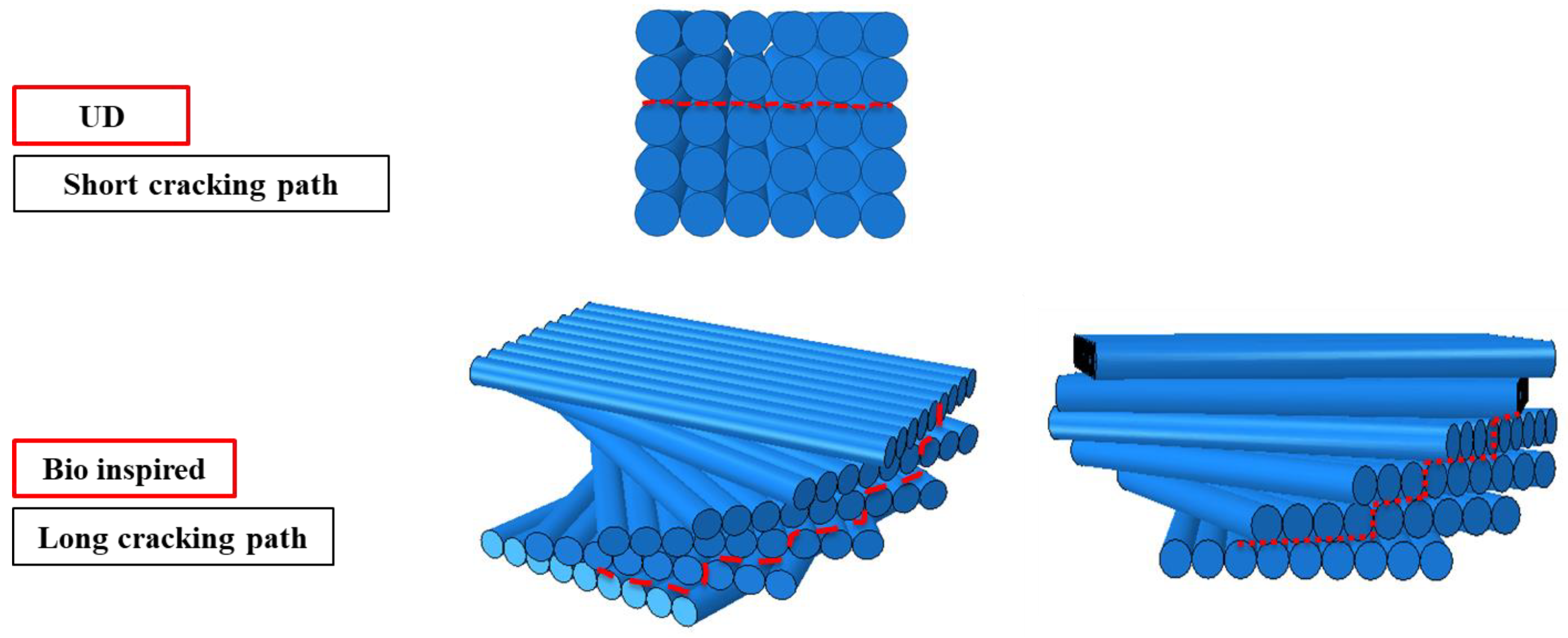
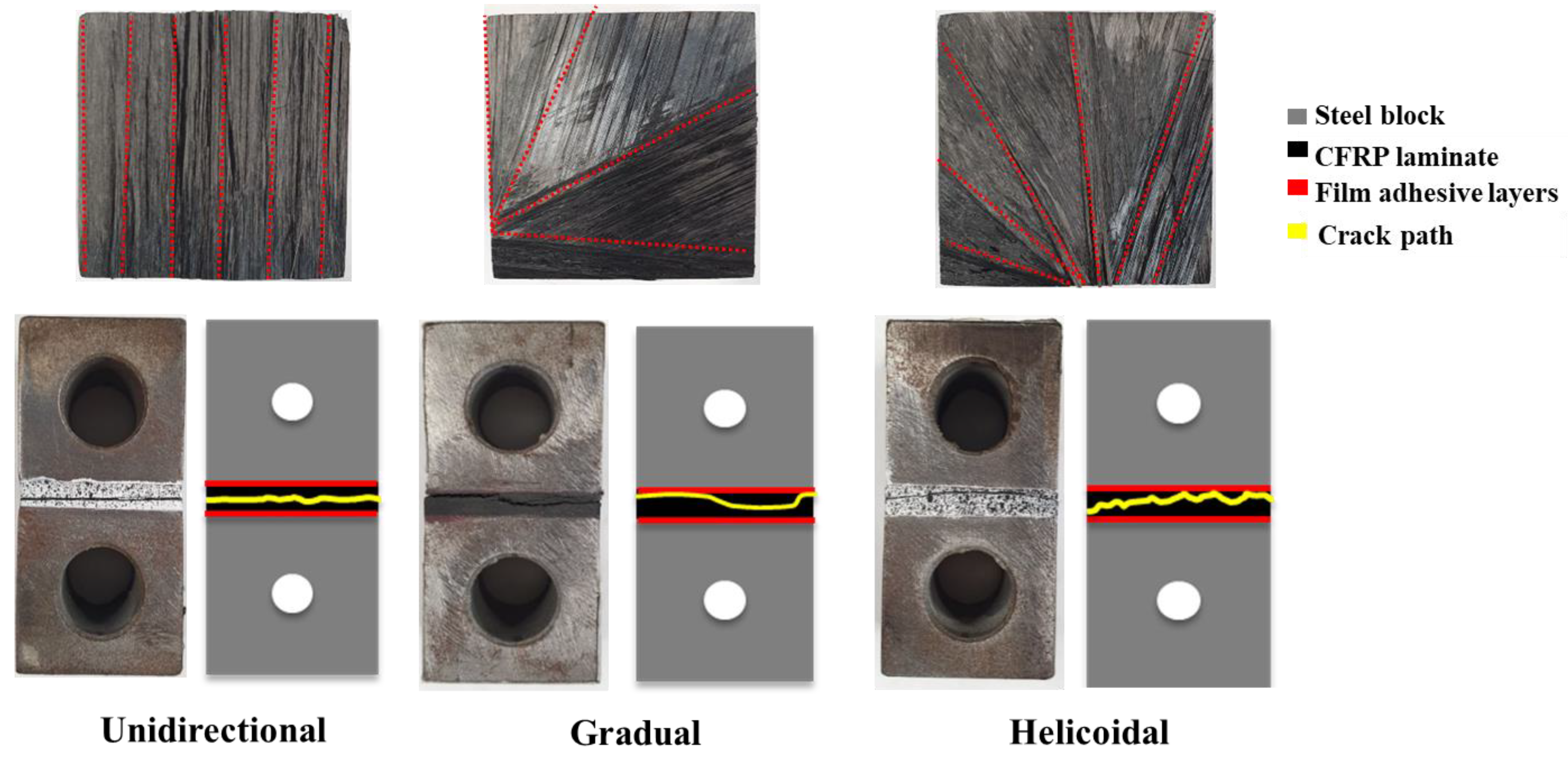
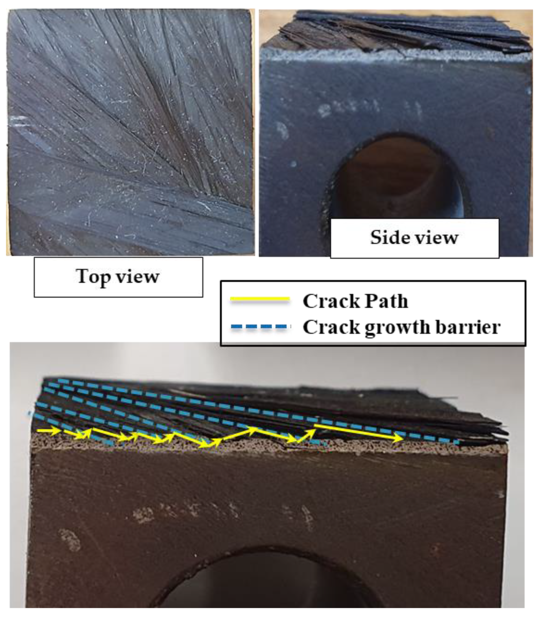
3.1.3. Influence of Bio-Inspired Configuration on Crack Morphology

The impact of various pitch angles on the failure mechanism can be assessed by examining the shear stress locus by using a proper static linear numerical simulation as discussed in Section 2.4. In each layer-i, the initiation of shearing cracks is a result of the maximum shear stress component. Consequently, within each layer-i, the anticipated formation of shearing cracks implies their occurrence at position(s) corresponding to the points where the shear stress component is maximized (there are two such points per layer, and in this study, the maximum absolute value is considered as maximum shear stress corresponding to each layer). Hence, the influence of the pitch angle on the location of shearing cracks can be evaluated by considering the locus of maximum shear stress of the ith layer.
Figure 7 displays the locus of the absolute maximum shear stress associated with the ith layer for helicoidal, gradual, and unidirectional configurations in panels a to c. As observed in the unidirectional laminate, the crack path follows a straight path, expanding through delamination and rarely growing throughout the thickness in different layers. In the helicoidal laminate, the cracks twist in the thickness direction, and due to the equal change in angle between adjacent layers (20°), the cracks follow a regular and homogeneous pattern. On the other hand, in the gradual laminate, which is characterized by different blocks of symmetry and nonlinear change in adjacent-layer orientation, the crack path exhibits a more intricate pattern. This complexity can have an impact on the strength of the laminate under transverse tensile loading.

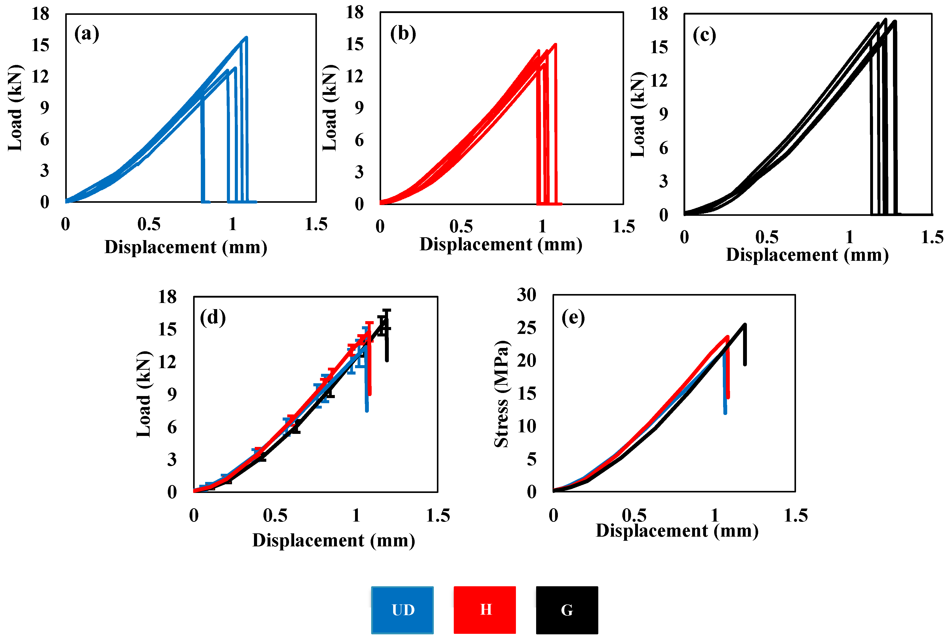
3.2. Experimental Results

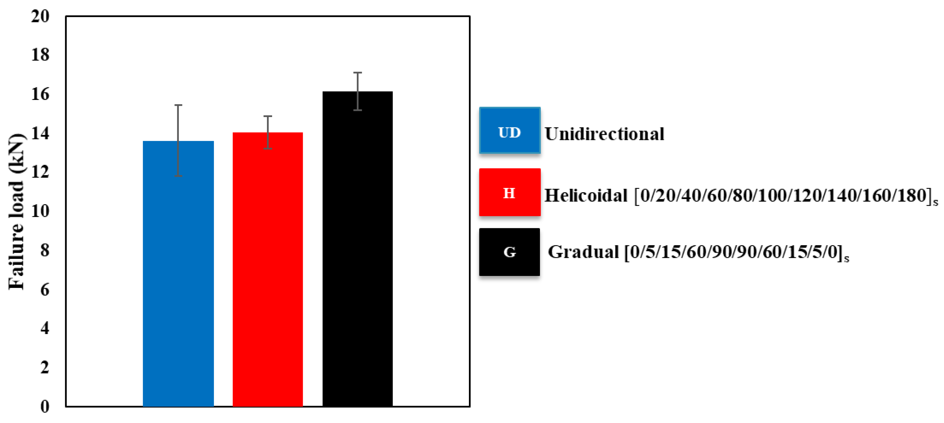
Influence of Bio-Inspired Configuration on Failure Load

Three distinct configurations, namely unidirectional, helicoidal, and gradual laminates, underwent testing, and the average resulted load–displacement and stress–strain curves are illustrated in Figure 8. To ensure data repeatability and bolster confidence in the presented average values, the Coefficient of Variation (CV) is computed for all configurations. The CV offers a standardized metric for variability compared to the mean, facilitating comparisons and assessing data consistency. The results indicate that the gradual and conventional helicoidal configurations display CVs of 6% and 4.8%, respectively, while the unidirectional configuration shows a slightly higher CV of 12%, all of which are considered acceptable.
A comparative analysis reveals that both helicoidal and gradual configurations exhibit higher failure loads when compared to unidirectional laminates. An increase of 17% in displacement at failure load is observed for the gradual composite laminate compared to the reference unidirectional configuration. This increase in displacement is approximately 5% for the helicoidal configuration when compared to the reference composite laminate. Therefore, it can be inferred that the bio-inspired configuration tends to exhibit greater toughness owing to the intricate nature of the failure mechanisms it experiences.
Figure 9 provides a summary of the experimentally obtained failure loads and the standard deviation for each configuration. In general, the experimental study indicates that the bio-inspired laminate exhibits higher strength compared to the unidirectional configuration. A detailed comparison between the failure loads of gradual and helicoidal laminates reveals that the failure load obtained from the gradual laminate is slightly higher than that exhibited by the helicoidal laminates (11%).

3.3. Discussion

The marginal distinction in the failure load among all configurations can be substantiated by the nearly equal distribution of von Mises stress for each configuration, as depicted in Figure 6b. Thus, the difference in failure load is primarily attributed to the more complex crack pattern throughout the thickness of bio-inspired configurations.
The distinct twisted pattern evident in the helicoidal and gradual configurations, indicated by the shear stress locus in Figure 7, further supports the observation of crack twisting in our experimental study. To clarify the twisting of cracks and the failure mechanisms in the studied configurations, Figure 10 depicts a schematic of the crack path. In the unidirectional configuration, the crack pattern is straight and relatively short. However, in the helicoidal laminate, the cracking path undergoes redirection, resulting in a longer crack path. This extended crack path plays a crucial role in effectively preventing catastrophic propagation of damage as delamination.
In Figure 11, the experimentally observed failure mechanisms for each configuration are presented. It is clear that within the unidirectional laminate, the propagation of cracks takes place smoothly, following a short and straight path. In unidirectional laminate, the dominant failure mode is interlaminar (delamination), which can be considered as more severe than intralaminar (matrix cracking) failure [29]. This is numerically demonstrated in Figure 7, where failure in the bio-inspired configuration is more intralaminar. Comparing the crack paths between the helicoidal and gradual configurations reveals that the helicoidal pattern, featuring a linear increase in pitch angle, results in regular failure surfaces that are distinguished with dotted red lines in Figure 11. Conversely, in the gradual configuration where the pitch angle increases nonlinearly, the failure surface shows irregular and severe changes. This can result in a more intricate crack path, offering higher strength.
In bio-inspired configurations, the failure starts with a shearing crack in ply-i (the layer below), then progresses along the fiber direction of the layer above (refer to Figure 12). As shown in Figure 12, in the bio-inspired configuration, the change in pitch angle acts as an effective barrier to crack propagation, offering higher strength and subsequently achieving a greater failure load. This complexity in crack path significantly enhances the ability of helicoidal and gradual laminates to resist and mitigate damage under applied loads. This experimental observation aligns with the explanations provided in Section 3.1.3 (Influence of bio-inspired configuration on crack morphology), highlighting the intricate crack path in bio-inspired laminates.

4. Conclusions

This research examined how the strength of composite laminates under transverse tensile loading is influenced by a bio-inspired design, incorporating both helicoidal and gradual changes in fiber orientation. Two stacking sequences, ([0/20/40/60/80/100/120/140/160/180]s and [0/5/15/60/90/90/60/15/5/0]s), denoted as helicoidal and gradual, were inspired from nature, manufactured, and subjected to transverse tensile tests for comparison with a reference composite laminate produced using a unidirectional composite. Numerical models of bio-mimetic CFRP laminates were created to analyze the influence of the pitch angle on the stress distribution and failure pattern of various manufactured configuration, as observed experimentally. Loci for the formation of delamination were subsequently analyzed, with a focus on shear stresses. The following conclusions can be drawn:
  • The numerical simulation indicates that the selected thickness of the laminates (3 mm) is sufficiently thin to keep the stress concentration effect on transverse tensile strength negligible.
  • The numerical study also indicated that delamination is prone to happen more in unidirectional laminates than in bio-inspired laminates.
  • The failure mechanism is significantly impacted by the angle between the layers. Where all layers are stacked in a 0-degree direction, the crack path is straight, making delamination more prone. Conversely, by introducing variations in the stacking sequence and incorporating bio-inspired laminates like helicoidal and gradual configurations, the crack path becomes longer and complex. Consequently, it is anticipated that both gradual and helicoidal laminates will exhibit greater strength when compared to unidirectional composites.
  • A rise in displacement at failure load was noted for both gradual and helicoidal configurations, showing an increase of 17% and 5%, respectively, compared to the reference unidirectional composite.
  • The gradual configuration demonstrates the highest strength (17% and 11% improvement in comparison with unidirectional and helicoidal configurations), attributed to the more intricate failure mechanism obtained through both numerical simulations and experimental observations.

Author Contributions

H.M.: Conceptualization, investigation, simulation, validation, and writing—original draft and editing.; R.J.C.C.: Conceptualization, supervision, and writing—review and editing; A.A.-S.: writing—review and editing; E.A.S.M.: writing—review and editing, M.F.: writing—review and editing; L.F.M.d.S.: conceptualization, writing—review and editing, and project administration. All authors have read and agreed to the published version of the manuscript.

Funding

This research was funded by Fundação para a Ciência e Tecnologia, grant number CEECIND/03276/2018.

Data Availability Statement

Data are contained within the article.

Acknowledgments

The authors gratefully acknowledge the Portuguese Foundation for Science and Technology (FCT) for supporting the work presented here, through individual grants CEECIND/03276/2018 ‘New approaches to improve the joint strength and reduce the delamination of composite adhesive joints’.

Conflicts of Interest

The authors declare no conflict of interest.

References

  1. Karataş, M.A.; Gökkaya, H. A review on machinability of carbon fiber reinforced polymer (CFRP) and glass fiber reinforced polymer (GFRP) composite materials. Def. Technol. 2018, 14, 318–326. [Google Scholar] [CrossRef]
  2. Clyne, T.W.; Hull, D. An Introduction to Composite Materials, 3rd ed.; Cambridge University Press: Cambridge, UK, 2019. [Google Scholar] [CrossRef]
  3. Shah, S.H.; Megat-Yusoff, P.S.M.; Karuppanan, S.; Choudhry, R.S.; Ahmad, F.; Sajid, Z.; Gerard, P.; Sharp, K. Performance comparison of resin-infused thermoplastic and thermoset 3D fabric composites under impact loading. Int. J. Mech. Sci. 2021, 189, 105984. [Google Scholar] [CrossRef]
  4. Peters, S.T. Introduction, Composite Basics and Road Map. In Handbook of Composites; Peters, S.T., Ed.; Springer: Boston, MA, USA, 1998; pp. 1–20. [Google Scholar] [CrossRef]
  5. Reddy, J.N. Mechanics of Laminated Composite Plates and Shells, 2nd ed.; CRC Press: Boca Raton, FL, USA, 2003. [Google Scholar] [CrossRef]
  6. Liu, L.; Zhang, X.; Wang, Z.; Wang, Y.; Guo, J. Micromechanics Modeling of Transverse Tensile Strength for Unidirectional CFRP Composite. Materials 2022, 15, 8577. [Google Scholar] [CrossRef] [PubMed]
  7. Shah, S.P.; Maiarù, M. analytical model for composite transverse strength based on computational micromechanics. Int. J. Multiscale Comput. Eng. 2023, 21, 77–97. [Google Scholar] [CrossRef]
  8. Camanho, P.P.; Dávila, C.G.; Pinho, S.T.; Iannucci, L.; Robinson, P. Prediction of in situ strengths and matrix cracking in composites under transverse tension and in-plane shear. Compos. Part A Appl. Sci. Manuf. 2006, 37, 165–176. [Google Scholar] [CrossRef]
  9. Malekinejad, H.; Ramezani, F.; Carbas, R.J.C.; Marques, E.A.S.; Ferreira, A.M.; da Silva, L.F.M. Study of CFRP Laminate Gradually Modified throughout the Thickness Using Thin Ply under Transvers Tensile Loading. Materials 2024, 17, 2388. [Google Scholar] [CrossRef]
  10. Garulli, T.; Katafiasz, T.J.; Greenhalgh, E.S.; Pinho, S.T. A novel bio-inspired microstructure for improved compressive performance of multidirectional CFRP laminates. Compos. B Eng. 2023, 264, 110867. [Google Scholar] [CrossRef]
  11. Melaibari, A.; Wagih, A.; Basha, M.; Kabeel, A.M.; Lubineau, G.; Eltaher, M.A. Bio-inspired composite laminate design with improved out-of-plane strength and ductility. Compos. Part A Appl. Sci. Manuf. 2021, 144, 106362. [Google Scholar] [CrossRef]
  12. Ning, J.; Zhang, J.; Pan, Y.; Guo, J. Fabrication and mechanical properties of SiO2 matrix composites reinforced by carbon nanotube. Mater. Sci. Eng. A 2003, 357, 392–396. [Google Scholar] [CrossRef]
  13. Cho, J.; Chen, J.Y.; Daniel, I.M. Mechanical enhancement of carbon fiber/epoxy composites by graphite nanoplatelet reinforcement. Scr. Mater. 2007, 56, 685–688. [Google Scholar] [CrossRef]
  14. Arteiro, A.; Catalanotti, G.; Reinoso, J.; Linde, P.; Camanho, P.P. Simulation of the Mechanical Response of Thin-Ply Composites: From Computational Micro-Mechanics to Structural Analysis. Arch. Comput. Methods Eng. 2019, 26, 1445–1487. [Google Scholar] [CrossRef]
  15. Heinemann, F.; Launspach, M.; Gries, K.; Fritz, M. Gastropod nacre: Structure, properties and growth—Biological, chemical and physical basics. Biophys. Chem. 2011, 153, 126–153. [Google Scholar] [CrossRef] [PubMed]
  16. Suksangpanya, N.; Yaraghi, N.A.; Kisailus, D.; Zavattieri, P. Twisting cracks in Bouligand structures. J. Mech. Behav. Biomed. Mater. 2017, 76, 38–57. [Google Scholar] [CrossRef] [PubMed]
  17. Mencattelli, L.; Pinho, S.T. Realising bio-inspired impact damage-tolerant thin-ply CFRP Bouligand structures via promoting diffused sub-critical helicoidal damage. Compos. Sci. Technol. 2019, 182, 107684. [Google Scholar] [CrossRef]
  18. Milliron, G.W. Lightweight Impact-Resistant Composite Materials: Lessons from Mantis Shrimp; University of California, Riverside: Riverside, CA, USA, 2012. [Google Scholar]
  19. Tadayon, M.; Amini, S.; Masic, A.; Miserez, A. The Mantis Shrimp Saddle: A Biological Spring Combining Stiffness and Flexibility. Adv. Funct. Mater. 2015, 25, 6437–6447. [Google Scholar] [CrossRef]
  20. Ramakrishna, D.; Murali, G.B. Bio-inspired 3D-printed lattice structures for energy absorption applications: A review. Proc. Inst. Mech. Eng. Part L J. Mater. Des. Appl. 2022, 237, 503–542. [Google Scholar] [CrossRef]
  21. Chouhan, G.; Murali, G.B. Uniform and graded bio-inspired gyroid lattice: Effects of post-curing and print orientation on mechanical property. Proc. Inst. Mech. Eng. Part L J. Mater. Des. Appl. 2023, 235, 14644207231200728. [Google Scholar] [CrossRef]
  22. Grunenfelder, L.K.; Suksangpanya, N.; Salinas, C.; Milliron, G.; Yaraghi, N.; Herrera, S.; Evans-Lutterodt, K.; Nutt, S.R.; Zavattieri, P.; Kisailus, D. Bio-inspired impact-resistant composites. Acta Biomater. 2014, 10, 3997–4008. [Google Scholar] [CrossRef]
  23. Cheng, L.; Thomas, A.; Glancey, J.L.; Karlsson, A.M. Mechanical behavior of bio-inspired laminated composites. Compos. Part A Appl. Sci. Manuf. 2011, 42, 211–220. [Google Scholar] [CrossRef]
  24. Jiang, H.; Ren, Y.; Liu, Z.; Zhang, S.; Lin, Z. Low-velocity impact resistance behaviors of bio-inspired helicoidal composite laminates with non-linear rotation angle-based layups. Compos. Struct. 2019, 214, 463–475. [Google Scholar] [CrossRef]
  25. Apichattrabrut, T.; Ravi-Chandar, K. Helicoidal Composites. Mech. Adv. Mater. Struct. 2006, 13, 61–76. [Google Scholar] [CrossRef]
  26. Abrate, S. Impact on Laminated Composite Materials. Appl. Mech. Rev. 1991, 44, 155–190. [Google Scholar] [CrossRef]
  27. Su, K. Delamination Resistance of Stitched Thermoplastic Matrix Composite Laminates; ASTM: West Conshohocken, PA, USA, 1989. [Google Scholar]
  28. Ginzburg, D.; Pinto, F.; Iervolino, O.; Meo, M. Damage tolerance of bio-inspired helicoidal composites under low velocity impact. Compos. Struct. 2017, 161, 187–203. [Google Scholar] [CrossRef]
  29. Hazzard, M.K.; Hallett, S.; Curtis, P.T.; Iannucci, L.; Trask, R.S. Effect of fibre orientation on the low velocity impact response of thin Dyneema® composite laminates. Int. J. Impact Eng. 2017, 100, 35–45. [Google Scholar] [CrossRef]
  30. Shang, J.S.; Ngern, N.H.H.; Tan, V.B.C. Crustacean-inspired helicoidal laminates. Compos. Sci. Technol. 2016, 128, 222–232. [Google Scholar] [CrossRef]
  31. Liu, J.L.; Lee, H.P.; Tan, V.B.C. Failure mechanisms in bioinspired helicoidal laminates. Compos. Sci. Technol. 2018, 157, 99–106. [Google Scholar] [CrossRef]
  32. Meo, M.; Rizzo, F.; Portus, M.; Pinto, F. Bioinspired Helicoidal Composite Structure Featuring Functionally Graded Variable Ply Pitch. Materials 2021, 14, 5133. [Google Scholar] [CrossRef] [PubMed]
  33. Tadayon, M.; Amini, S.; Wang, Z.; Miserez, A. Biomechanical Design of the Mantis Shrimp Saddle: A Biomineralized Spring Used for Rapid Raptorial Strikes. iScience 2018, 8, 271–282. [Google Scholar] [CrossRef] [PubMed]
  34. Cheng, L.; Wang, L.; Karlsson, A.M. Image analyses of two crustacean exoskeletons and implications of the exoskeletal microstructure on the mechanical behavior. J. Mater. Res. 2008, 23, 2854–2872. [Google Scholar] [CrossRef]
  35. Kim, K.S.; Hahn, H.T. Residual stress development during processing of graphite/epoxy composites. Compos. Sci. Technol. 1989, 36, 121–132. [Google Scholar] [CrossRef]
  36. Palmares, M.; Carbas, R.; Silva, L.F.M. Strength of Hybrid Laminates Aluminium Carbon-Fibre Joints with Different Lay-up Configurations. Master Thesis, Faculty of Engineering of Porto University, Porto, Portugal, 2016. [Google Scholar]
  37. Campilho, R.D.S.G.; de Moura, M.F.S.F.; Domingues, J.J.M.S. Modelling single and double-lap repairs on composite materials. Compos. Sci. Technol. 2005, 65, 1948–1958. [Google Scholar] [CrossRef]
  38. Hara, E.; Yokozeki, T.; Hatta, H.; Ishikawa, T.; Iwahori, Y. Effects of geometry and specimen size on out-of-plane tensile strength of aligned CFRP determined by direct tensile method. Compos. Part A Appl. Sci. Manuf. 2010, 41, 1425–1433. [Google Scholar] [CrossRef]
  39. Choi, H.Y.; Chang, F.-K. A Model for Predicting Damage in Graphite/Epoxy Laminated Composites Resulting from Low-Velocity Point Impact. J. Compos. Mater. 1992, 26, 2134–2169. [Google Scholar] [CrossRef]
  40. Ramezani, F.; Carbas, R.; Marques, E.A.S.; Ferreira, A.M.; da Silva, L.F.M. Study on out-of-plane tensile strength of angle-plied reinforced hybrid CFRP laminates using thin-ply. Mech. Adv. Mater. Struct. 2023, 31, 2859–2872. [Google Scholar] [CrossRef]
Figure 2. (a) Unidirectional laminate; (b) Conventional helicoidal laminate [0/20/40/60/80/100/120/140/160/180]s; (c) Gradual helicoidal laminate [0/5/15/60/90/90/60/15/5/0]s.
Jcs 08 00228 g002
Figure 3. Schematic design of steel blocks attached to conventional composite blocks and loading condition.
Jcs 08 00228 g003
Figure 4. Loading and boundary conditions applied to the model.
Jcs 08 00228 g004
Figure 5. Effect of laminate thickness on stress ratio.
Jcs 08 00228 g005
Figure 6. (a) Shear stress; (b) von Mises stress corresponded to each layer for unidirectional (UD), helicoidal (H), and gradual (G) configurations.
Jcs 08 00228 g006
Figure 7. Locus of maximum shear stress corresponded to each layer along the thickness: (a) unidirectional, (b) helicoidal, (c) gradual.
Jcs 08 00228 g007
Figure 8. Load–displacement curves for (a) unidirectional (UD), (b) helicoidal (H), and (c) gradual (G) configurations; (d) average load–displacement curves corresponded to each configuration; (e) stress–displacement curves corresponded to each configuration.
Jcs 08 00228 g008
Figure 9. Average failure loads for laminates with unidirectional CFRP, helicoidal-oriented CFRP and gradual-oriented CFRP.
Jcs 08 00228 g009
Figure 10. Comparative analysis of the impact response in composites with and without helicoidal structure (reproduced with permission from Elsevier).
Jcs 08 00228 g010
Figure 11. Failure mechanism for unidirectional, helicoidal, and gradual configurations.
Jcs 08 00228 g011
Figure 12. Cracks started along the above fiber layer direction.
Jcs 08 00228 g012
Table 1. Laminates manufactured with varied stacking sequences.
Laminate TitlePly Stacking Sequence
Unidirectional (UD)[0]20
Helicoidal (H)[0/20/40/60/80/100/120/140/160/180]s
Gradual (G)[0/5/15/60/90/90/60/15/5/0]s
Table 2. Mechanical properties of the CFRP laminates [37].
Ex (Mpa)Ey (Mpa)Ez (Mpa)ʋxyʋxzʋyzGxy (Mpa)Gxz (Mpa)Gyz (Mpa)
109,000881988190.3420.3420.380431543153200
Disclaimer/Publisher’s Note: The statements, opinions and data contained in all publications are solely those of the individual author(s) and contributor(s) and not of MDPI and/or the editor(s). MDPI and/or the editor(s) disclaim responsibility for any injury to people or property resulting from any ideas, methods, instructions or products referred to in the content.

