
Stress Analysis of Tibial Bone Using Three Different Materials for Bone Fixation Plates

 ,
, 
Abstract
1. Introduction
2. Materials and Methods
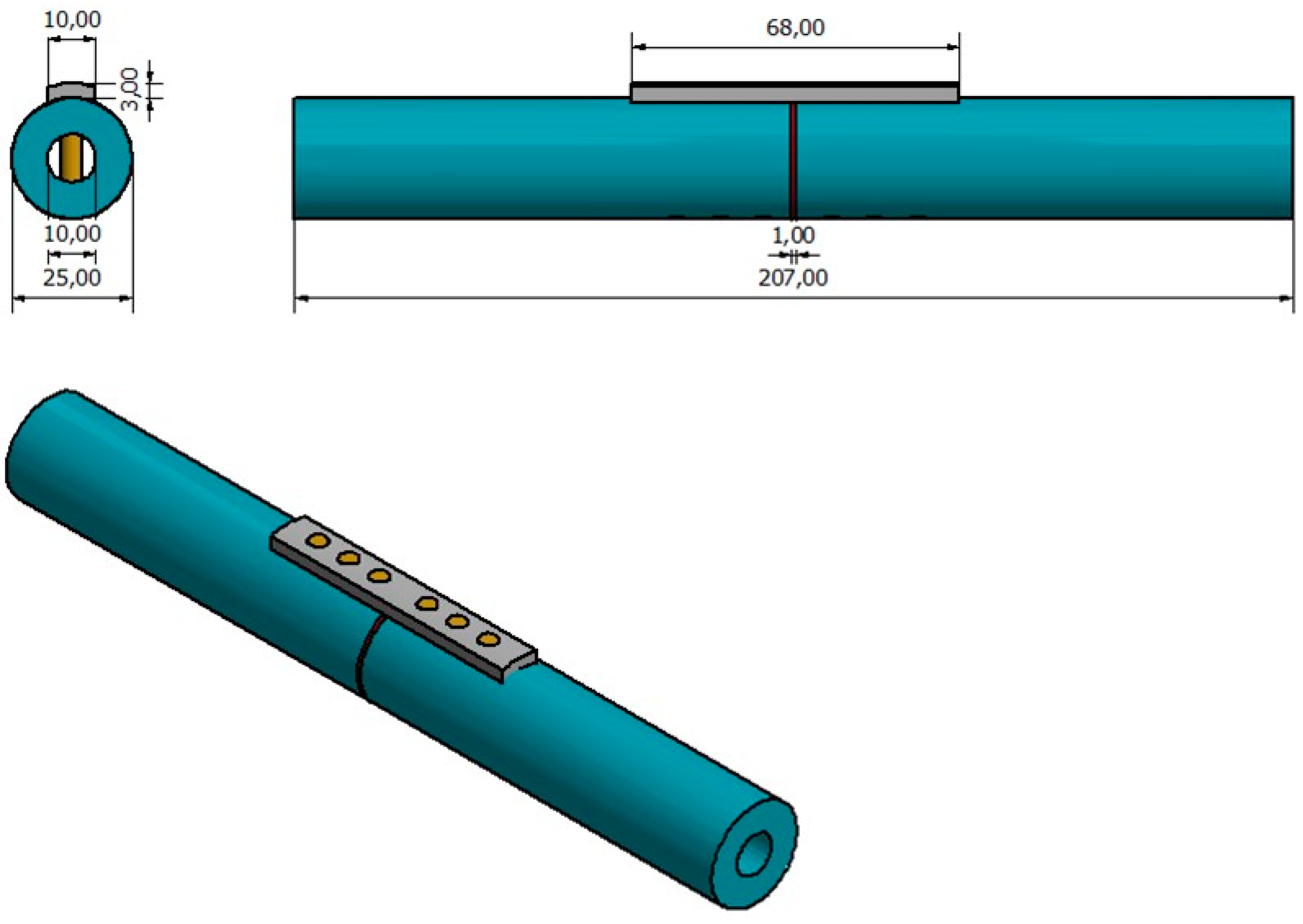
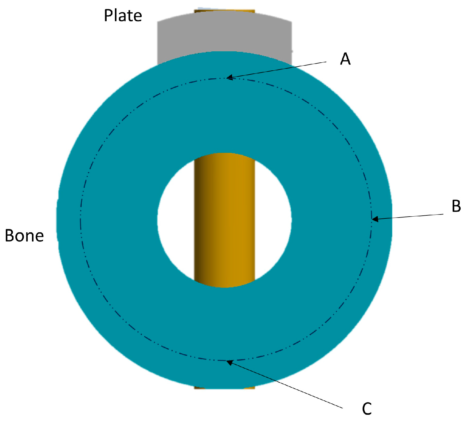
2.1. Model Geometry
2.2. Material Properties
- -
- Titanium alloy, Ti-6Al-4V;
- -
- Magnesium alloy, ZM21;
- -
- Carbon fiber reinforced PEEK (CFRP) composite material.
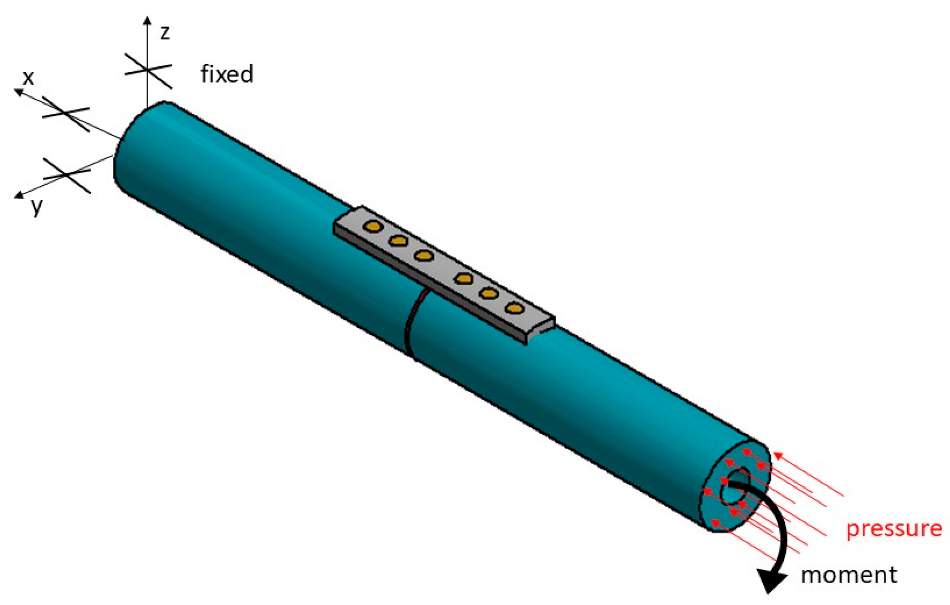
2.3. Loading and Kinematic Boundary Conditions
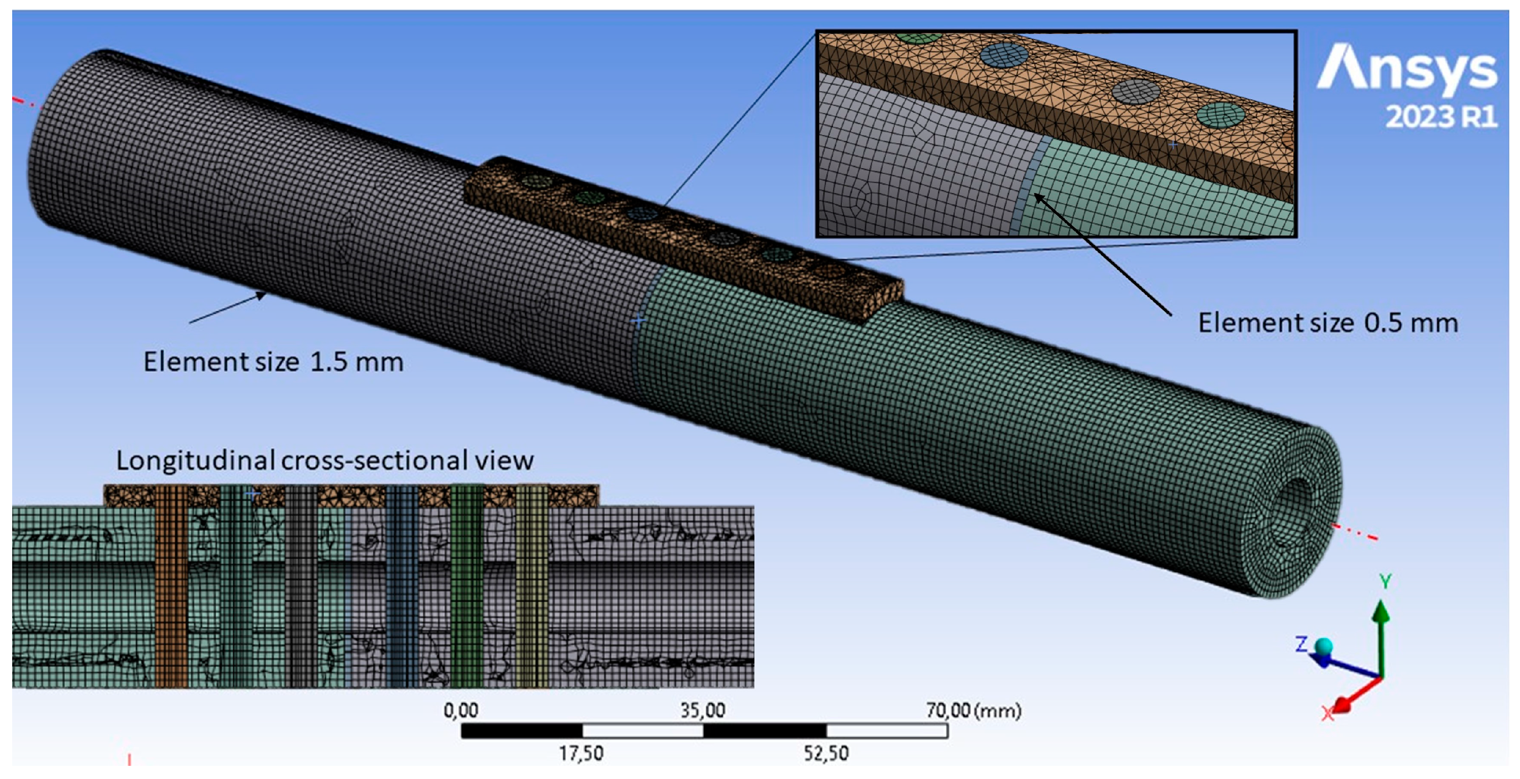
2.4. Finite Element Model
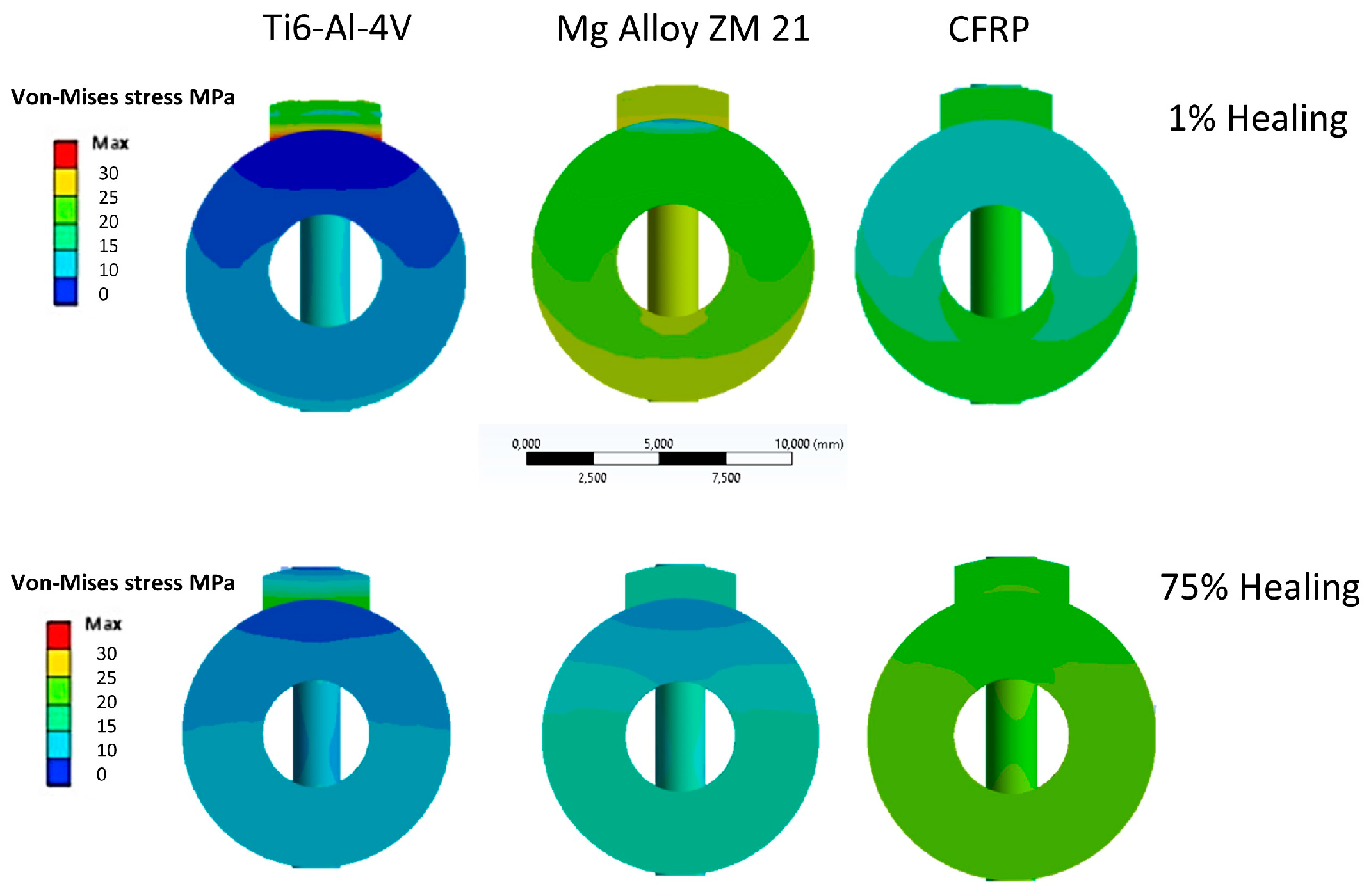
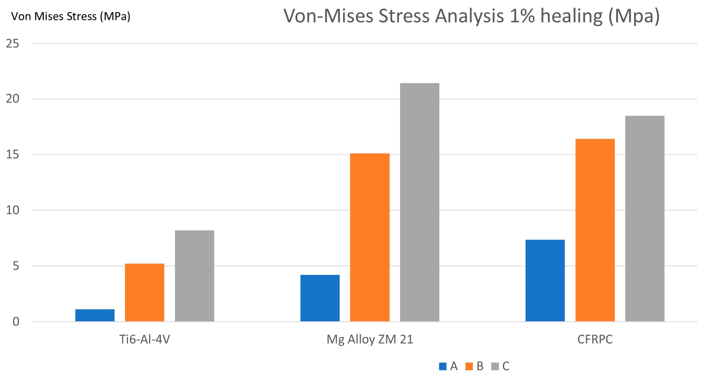
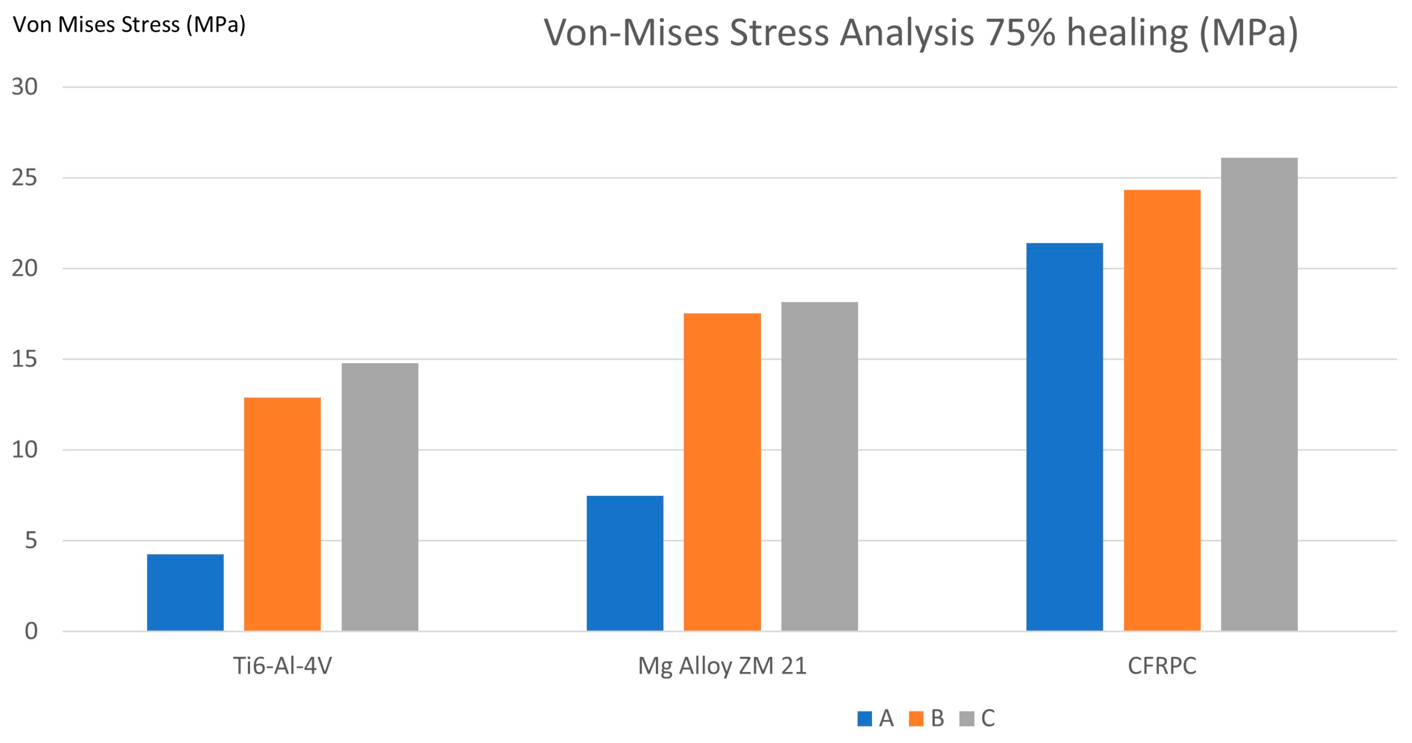
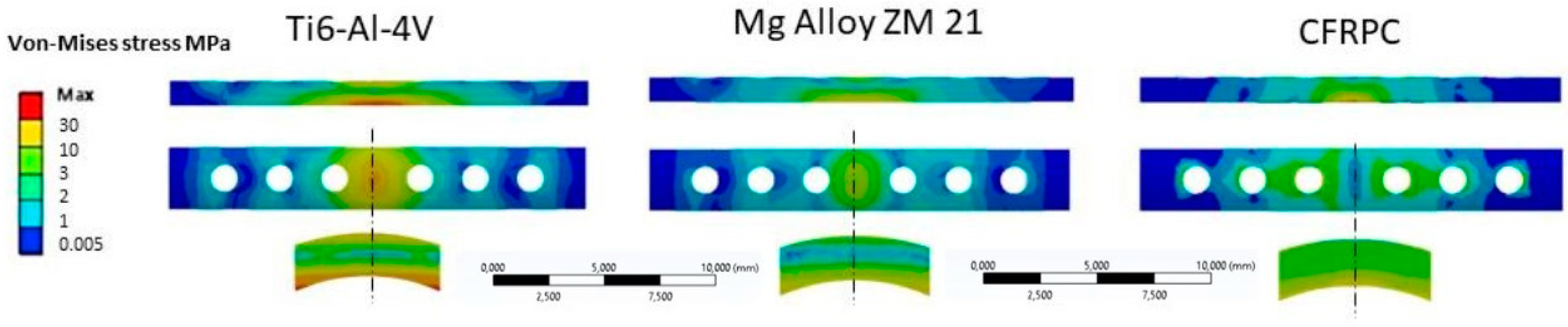
3. Results
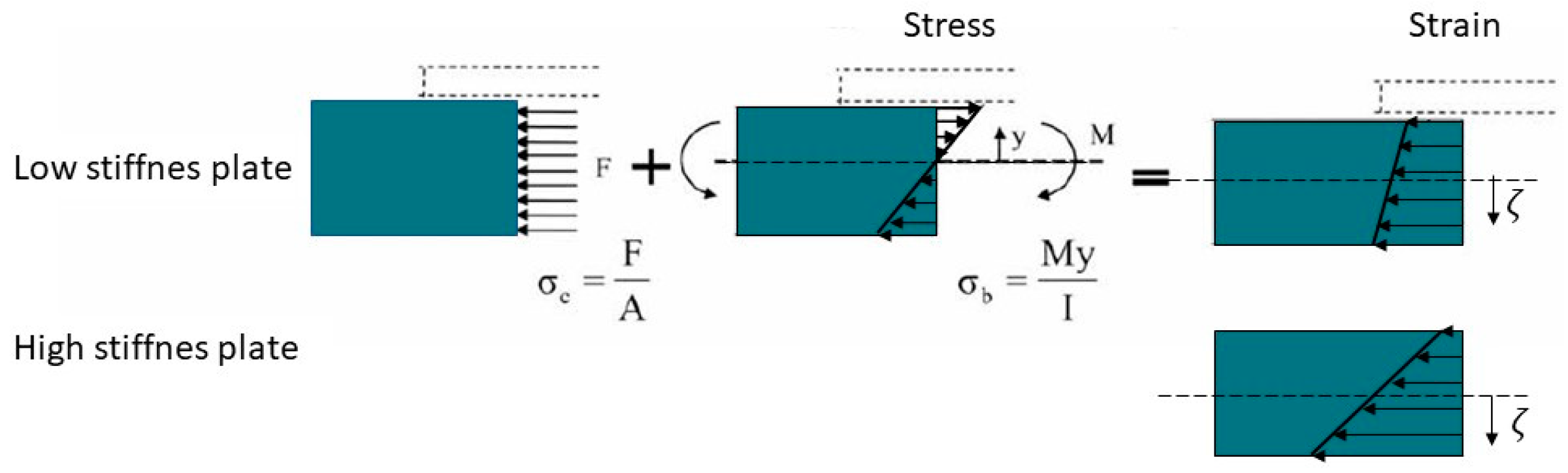
4. Discussion
5. Conclusions
Author Contributions
Funding
Institutional Review Board Statement
Informed Consent Statement
Data Availability Statement
Conflicts of Interest
References
- Gordon, J.E.; O’Donnell, J.C. Tibia fractures: What should be fixed? J. Pediatr Orthop. 2012, 32 (Suppl. S1), S52–S61. [Google Scholar] [CrossRef]
- Beale, B.; McCally, R. Minimally invasive fracture repair of the tibia and fibula. Vet. Clin. N. Am. Small. Anim. Pract. 2020, 50, 183–206. [Google Scholar] [CrossRef]
- Prasad, M.; Yadav, S.; Sud, A.; Arora, N.C.; Kumar, N.; Singh, S. Assessment of the role of fibular fixation in distal-third tibia-fibula fractures and its significance in decreasing malrotation and malalignment. Injury 2013, 44, 1885–1891. [Google Scholar] [CrossRef]
- Einhorn, T.A.; Gerstenfeld, L.C. Fracture healing: Mechanisms and interventions. Nat. Rev. Rheumatol. 2015, 11, 45–54. [Google Scholar] [CrossRef]
- Claes, L.; Recknagel, S.; Ignatius, A. Fracture healing under healthy and inflammatory conditions. Nat. Rev. Rheumatol. 2012, 8, 133–143. [Google Scholar] [CrossRef]
- Marsell, R.; Einhorn, T.A. The biology of fracture healing. Injury 2011, 42, 551–555. [Google Scholar] [CrossRef]
- Li, J.; Qin, L.; Yang, K.; Ma, Z.; Wang, Y.; Cheng, L.; Zhao, D. Materials evolution of bone plates for internal fixation of bone fractures: A review. J. Mater. Sci. Technol. 2020, 36, 190–208. [Google Scholar] [CrossRef]
- Palanisamy, P.; Alam, M.; Li, S.; Chow, S.K.H.; Zheng, Y.P. Low-intensity pulsed ultrasound stimulation for bone fractures healing: A review. J. Ultrasound Med. 2022, 41, 547–563. [Google Scholar] [CrossRef]
- Dhason, R.; Roy, S.; Datta, S. Metal and composite bone plates for B1 periprosthetic femoral fracture in healthy and osteoporotic condition: A comparative biomechanical study. Int. J. Artif. Organs. 2022, 45, 704–714. [Google Scholar] [CrossRef]
- Samiezadeh, S.; Tavakkoli Avval, P.; Fawaz, Z.; Bougherara, H. On optimization of a composite bone plate using the selective stress shielding approach. J. Mech. Behav. Biomed. Mater. 2015, 42, 138–153. [Google Scholar] [CrossRef]
- Iwai, T.; Omura, S.; Aoki, N.; Tohnai, I. Use of self-tapping metal screws for temporary fixation of a resorbable plate system in maxillofacial surgery. J. Craniofac. Surg. 2015, 26, 891–892. [Google Scholar] [CrossRef]
- Zdero, R.; Gide, K.; Brzozowski, P.; Schemitsch, E.H.; Bagheri, Z.S. Biomechanical design optimization of distal femur locked plates: A review. Proc. Inst. Mech. Eng. H J. Eng. Med. 2023, 237, 791–805. [Google Scholar] [CrossRef]
- Al-Tamimi, A.A.; Fernandes, P.R.A.; Peach, C.; Cooper, G.; Diver, C.; Bartolo, P.J. Metallic bone fixation implants: A novel design approach for reducing the stress shielding phenomenon. Virtual Phys. Prototyp. 2017, 12, 141–151. [Google Scholar] [CrossRef]
- Al-Tamimi, A.A.; Peach, C.; Fernandes, P.R.; Cseke, A.; Bartolo, P.J.D.S. Topology optimization to reduce the stress shielding effect for orthopedic applications. Procedia CIRP 2017, 65, 202–206. [Google Scholar] [CrossRef]
- Witte, F.; Kaese, V.; Haferkamp, H.; Switzer, E.; Meyer-Lindenberg, A.; Wirth, C.J.; Windhagen, H. In vivo corrosion of four magnesium alloys and the associated bone response. Biomaterials 2005, 26, 3557–3563. [Google Scholar] [CrossRef]
- Yamasaki, Y.; Yoshida, Y.; Okazaki, M.; Shimazu, A.; Kubo, T.; Akagawa, Y.; Uchida, T. Action of FGMgCO 3Ap–collagen composite in promoting bone formation. Biomaterials 2003, 24, 4913–4920. [Google Scholar] [CrossRef]
- Castellani, C.; Lindtner, R.A.; Hausbrandt, P.; Tschegg, E.K.; Stanzl-Tschegg, S.; Zanoni, G.; Beck, S.; Weinberg, A.M. Bone-implant interface strength and osseointegration: Biodegradable magnesium alloy versus standard titanium control. Acta Biomater. 2011, 7, 432–440. [Google Scholar] [CrossRef] [PubMed]
- Du, Z.; Yu, X.; Nie, B.; Zhu, Z.; Ibrahim, M.; Yang, K.; Tan, L.; Wang, Y. Effects of magnesium coating on bone-implant interfaces with and without polyether-ether-ketone particle interference: A rabbit model based on porous Ti6Al4V implants. J. Biomed. Mater. Res. B Appl. Biomater. 2019, 107, 2388–2396. [Google Scholar] [CrossRef]
- Nasr Azadani, M.; Zahedi, A.; Bowoto, O.K.; Oladapo, B.I. A review of current challenges and prospects of magnesium and its alloy for bone implant applications. Prog. Biomater. 2022, 11, 1–26. [Google Scholar] [CrossRef]
- Yang, Y.; Wu, Y.; Wei, Y.; Zeng, T.; Cao, B.; Liang, J. Preparation and characterization of hydroxyapatite coating on AZ31 magnesium alloy induced by carboxymethyl cellulose dopamine. Materials 2021, 14, 1849. [Google Scholar] [CrossRef]
- Gu, X.; Zhou, W.; Zheng, Y.; Cheng, Y.; Wei, S.; Zhong, S.; Xi, T.F.; Chen, L.J. Corrosion fatigue behaviors of two biomedical Mg alloys—AZ91D and WE43 in simulated body fluid. Acta Biomater. 2010, 6, 4605–4613. [Google Scholar] [CrossRef]
- Ceddia, M.; Trentadue, B.; De Giosa, G.; Solarino, G. Topology optimization of a femoral stem in titanium and carbon to reduce stress shielding with the FEM method. J. Compos. Sci. 2023, 7, 298. [Google Scholar] [CrossRef]
- Wang, J.; Dou, J.; Wang, Z.; Hu, C.; Yu, H.; Chen, C. Research progress of biodegradable magnesium-based biomedical materials: A review. J. Alloys Compd. 2022, 923, 166377. [Google Scholar] [CrossRef]
- Ortega-Martínez, J.; Farré-Lladós, M.; Cano-Batalla, J.; Cabratosa-Termes, J. Polyetheretherketone (PEEK) as a medical and dental material. A literature review. Med. Res. Arch. 2017, 5, 1–16. [Google Scholar] [CrossRef]
- Mehboob, H.; Chang, S.-H. Effect of structural stiffness of composite bone plate–scaffold assembly on tibial fracture with large fracture gap. Compos. Struct. 2015, 124, 327–336. [Google Scholar] [CrossRef]
- Liao, C.; Li, Y.; Tjong, S.C. Polyetheretherketone and its composites for bone replacement and regeneration. Polymers 2020, 12, 2858. [Google Scholar] [CrossRef]
- Hassani, K.; Nikkhoo, M.; Karimi, A. The role of the fiber ply configurations on the biomechanics of the hip prosthesis. Int. J. Model. Simul. Sci. Comp. 2022, 13, 2250017. [Google Scholar] [CrossRef]
- Abdellah, M.Y.; Alharthi, H.; Hassan, M.K.; Mohamed, A.F. Effect of specimen size on natural vibration of open hole copper/glass-reinforced epoxy laminate composites. AIMS Mater. Sci. 2020, 7, 499–517. [Google Scholar] [CrossRef]
- Laux, C.J.; Hodel, S.M.; Farshad, M.; Müller, D.A. Carbon fibre/polyether ether ketone (CF/PEEK) implants in orthopaedic oncology. World J. Surg. Oncol. 2018, 16, 241. [Google Scholar] [CrossRef]
- Fujihara, K.; Huang, Z.M.; Ramakrishna, S.; Satknanantham, K.; Hamada, H. Feasibility of knitted carbon/PEEK composites for orthopedic bone plates. Biomaterials 2004, 25, 3877–3885. [Google Scholar] [CrossRef]
- Kim, S.H.; Chang, S.H.; Jung, H.J. The finite element analysis of a fractured tibia applied by composite bone plates considering contact conditions and time-varying properties of curing tissues. Compos. Struct. 2010, 92, 2109–2118. [Google Scholar] [CrossRef]
- Zhang, C.; Wen, P.; Xu, Y.; Fu, Z.; Ren, G. Exploring advanced functionalities of carbon fiber-graded PEEK composites as bone fixation plates using finite element analysis. Materials 2024, 17, 414. [Google Scholar] [CrossRef]
- Fouda, N.; Mostafa, R.; Saker, A. Numerical study of stress shielding reduction at fractured bone using metallic and composite bone-plate models. Ain Shams Eng. J. 2019, 10, 481–488. [Google Scholar] [CrossRef]
- Benli, S.; Aksoy, S.; Havıtcıoglu, H.; Kucuk, M. Evaluation of bone plate with low-stiffness material in terms of stress distribution. J. Biomech. 2008, 41, 3229–3235. [Google Scholar] [CrossRef]
- Shirurkar, A.; Tamboli, A.; Jagtap, P.N.; Dondapati, S.; Davidson, J.D. Mechanical behavior of ZM21 magnesium alloy locking plates–an experimental and finite element study. Mater. Today Proc. 2017, 4, 6728–6736. [Google Scholar] [CrossRef]
- Guo, L.; Naghavi, S.A.; Wang, Z.; Varma, S.N.; Han, Z.; Yao, Z.; Wang, L.; Wang, L.; Liu, C. On the design evolution of hip implants: A review. Mater. Des. 2022, 216, 110552. [Google Scholar] [CrossRef]
- Chang, L.; Wang, H.; Guo, Y.; Cai, Z.; Zhan, H. Experimental and numerical analysis of biomechanical effects in cervical spine positioning rotation manipulation. Int. J. Numer. Methods Biomed. Eng. 2022, 38, e3651. [Google Scholar] [CrossRef]
- Ceddia, M.; Solarino, G.; Giannini, G.; De Giosa, G.; Tucci, M.; Trentadue, B. A Finite element analysis study of influence of femoral stem material in stress shielding in a model of uncemented total hip arthroplasty: Ti-6Al-4V versus carbon fibre-reinforced PEEK composite. J. Compos. Sci. 2024, 8, 254. [Google Scholar] [CrossRef]
- Darwich, A.; Nazha, H.; Daoud, M. Effect of coating materials on the fatigue behavior of hip implants: A three-dimensional finite element analysis. J. Appl. Comput. Mech. 2020, 6, 284–295. [Google Scholar]
- Ganesh, V.K.; Ramakrishna, K.; Ghista, D.N. Biomechanics of bone-fracture fixation by stiffness-graded plates in comparison with stainless-steel plates. Biomed. Eng. Online 2005, 4, 46. [Google Scholar] [CrossRef]
- Lanyon, L.E. Using functional loading to influence bone mass and architecture: Objectives, mechanisms, and relationship with estrogen of the mechanically adaptive process in bone. Bone 1996, 18, S37–S43. [Google Scholar] [CrossRef]
- Ahirwar, H.; Gupta, V.K.; Nanda, H.S. Finite element analysis of fixed bone plates over fractured femur model. Comput. Methods Biomech. Biomed. Eng. 2021, 24, 1742–1751. [Google Scholar] [CrossRef]
- Perren, S.M. Evolution of the internal fixation of long bone fractures. The scientific basis of biological internal fixation: Choosing a new balance between stability and biology. J. Bone Joint. Surg. 2002, 84, 1093–1110. [Google Scholar] [CrossRef]
- Pater, T.J.; Grindel, S.I.; Schmeling, G.J.; Wang, M. Stability of unicortical locked fixation versus bicortical non-locked fixation for forearm structures. Bone Res. 2014, 2, 14014. [Google Scholar] [CrossRef]
- Nourisa, J.; Rouhi, G. Biomechanical evaluations of intramedullary nail and bone plate for the fixation of distal metaphyseal fractures. J. Mech. Behav. Biomed. Mater. 2016, 56, 34–44. [Google Scholar] [CrossRef]
- Niinomi, N. Recent metallic materials for biomedical applications. Metall. Mater. Trans. A 2002, 33, 477–486. [Google Scholar] [CrossRef]
- Al-Shalawi, F.D.; Mohamed Ariff, A.H.; Jung, D.W.; Mohd Ariffin, M.K.A.; Seng Kim, C.L.; Brabazon, D.; Al-Osaimi, M.O. Biomaterials as implants in the orthopedic field for regenerative medicine: Metal versus synthetic polymers. Polymers 2023, 15, 2601. [Google Scholar] [CrossRef]
- Szewczenko, J.; Marciniak, J.; Kajzer, W.; Kajzer, A. Evaluation of corrosion resistance of titanium alloys used for medical implants. Arch. Metall. Mater. 2016, 61, 695–700. [Google Scholar] [CrossRef]
- Azevedo, C.R.F. Failure analysis of a commercially pure titanium plate for osteosynthesis. Eng. Fail. Anal. 2003, 10, 153–164. [Google Scholar] [CrossRef]
- Chandra, G.; Pandey, A. Design approaches and challenges for biodegradable bone implants: A review. Expert Rev. Med. Devices 2021, 18, 629–647. [Google Scholar] [CrossRef]
- Kennady, M.C.; Tucker, M.R.; Lester, G.E.; Buckley, M.J. Stress shielding effect of rigid internal fixation plates on mandibular bone grafts. A photon absorption densitometry and quantitative computerized tomographic evaluation. Int. J. Oral Maxillofac. Surg. 1989, 18, 307–310. [Google Scholar] [CrossRef]
- Kennedy, S.M.; Vasanthanathan, A.; Robert, R.B.J.; Amudhan, K. Advancements and prospects of polymer-based hybrid composites for bone plate applications. Polym-Plast. Technol. Mater. 2024, 63, 68–87. [Google Scholar] [CrossRef]
- Chandra, G.; Pandey, A. Preparation strategies for Mg-alloys for biodegradable orthopaedic implants and other biomedical applications: A review. Irbm 2022, 43, 229–249. [Google Scholar] [CrossRef]
- Abd Razak, S.I.; Ahmad Sharif, N.F.; Abdul Rahman, W.A.W. Biodegradable polymers and their bone applications: A review. Int. J. Basic Appl. Sci. 2012, 12, 31–49. [Google Scholar]
- Cox, T.; Kohn, M.W.; Impelluso, T. Computerized analysis of resorbable polymer plates and screws for the rigid fixation of mandibular angle fractures. Int. J. Oral Maxillofac. Surg. 2003, 61, 481–487. [Google Scholar] [CrossRef]
- Schliemann, B.; Wähnert, D.; Theisen, C.; Herbort, M.; Kösters, C.; Raschke, M.J.; Weimann, A. How to enhance the stability of locking plate fixation of proximal humerus fractures? An overview of current biomechanical and clinical data. Injury 2015, 46, 1207–1214. [Google Scholar] [CrossRef]
- Byun, S.H.; Lim, H.K.; Cheon, K.H.; Lee, S.M.; Kim, H.E.; Lee, J.H. Biodegradable magnesium alloy (WE43) in bone—Fixation plate and screw. J. Biomed. Mater. Res. B Appl. Biomater. 2020, 108, 2505–2512. [Google Scholar] [CrossRef]
- Fischer, H.; Schmidt-Bleek, O.; Orassi, V.; Wulsten, D.; Schmidt-Bleek, K.; Heiland, M.; Steffen, C.; Rendenbach, C. Biomechanical comparison of WE43-based magnesium vs. titanium miniplates in a mandible fracture model in sheep. Materials 2022, 16, 102. [Google Scholar] [CrossRef]
- Zhi, P.; Liu, L.; Chang, J.; Liu, C.; Zhang, Q.; Zhou, J.; Liu, Z.; Fan, Y. Advances in the study of magnesium alloys and their use in bone implant material. Metals 2022, 12, 1500. [Google Scholar] [CrossRef]
- He, M.; Chen, L.; Yin, M.; Xu, S.; Liang, Z. Review on magnesium and magnesium-based alloys as biomaterials for bone immobilization. J. Mater. Res. Technol. 2023, 23, 4396–4419. [Google Scholar] [CrossRef]
- Antoniac, I.; Miculescu, M.; Mănescu, V.; Stere, A.; Quan, P.H.; Păltânea, G.; Robu, A.; Earar, K. Magnesium-based alloys used in orthopedic surgery. Materials 2022, 15, 1148. [Google Scholar] [CrossRef] [PubMed]
- Luo, Y.; Wang, J.; Ong, M.T.Y.; Yung, P.S.H.; Wang, J.; Qin, L. Update on the research and development of magnesium-based biodegradable implants and their clinical translation in orthopaedics. Biomater. Transl. 2021, 2, 188–196. [Google Scholar] [PubMed]
- Perić Kačarević, Ž.; Rider, P.; Alkildani, S.; Retnasingh, S.; Pejakić, M.; Schnettler, R.; Gosau, M.; Smeets, R.; Jung, O.; Barbeck, M. An introduction to bone tissue engineering. Int. J. Artif. Organs 2020, 43, 69–86. [Google Scholar] [CrossRef]
- Hsissou, R.; Seghiri, R.; Benzekri, Z.; Hilali, M.; Rafik, M.; Elharfi, A. Polymer composite materials: A comprehensive review. Compos. Struct. 2021, 262, 113640. [Google Scholar] [CrossRef]
- Gupta, R.; Mitchell, D.; Blanche, J.; Harper, S.; Tang, W.; Pancholi, K.; Baines, L.; Bucknall, D.G.; Flynn, D. A review of sensing technologies for non-destructive evaluation of structural composite materials. J. Compos. Sci. 2021, 5, 319. [Google Scholar] [CrossRef]
- Ceddia, M.; Trentadue, B. A review of carbon fiber-reinforced polymer composite used to solve stress shielding in total hip replacement. AIMS Mater. Sci. 2024, 11, 449–462. [Google Scholar] [CrossRef]
- Senthil Maharaj, P.S.R.; Vasanthanathan, A. An insight into the mechanical and tribological behavior of carbon-flax reinforced bioepoxy hybrid composite bone plates for orthopedic applications. Polym. Polym. Compos. 2023, 31, 09673911231178444. [Google Scholar] [CrossRef]
- Jafari Chashmi, M.; Fathi, A.; Shirzad, M.; Jafari-Talookolaei, R.A.; Bodaghi, M.; Rabiee, S.M. Design and analysis of porous functionally graded femoral prostheses with improved stress shielding. Designs 2020, 4, 12. [Google Scholar] [CrossRef]
- Petersen, R. Carbon Fiber Biocompatibility for Implants. Fibers 2016, 4, 1. [Google Scholar] [CrossRef]


| Material | Ex (GPa) | Ey (GPa) | Ez (GPa) | Gxy (GPa) | Gyz GPa) | Gxz (GPa) | |||
|---|---|---|---|---|---|---|---|---|---|
| Bone | 18.400 | 7.000 | 8.500 | 2.410 | 3.560 | 3.560 | 0.12 | 0.37 | 0.14 |
| Fractured Bone | 0.2 (1% healing) 15.00 (75% healing) | 0.3 0.3 | |||||||
| Ti-6Al-4V | 110 | 110 | 110 | 0.3 | |||||
| Mg Alloy ZM 21 | 45 | 45 | 45 | 0.35 | |||||
| CFRP | 4 | 9.8 | 9.8 | 3.5 | 3 | 3.5 | 0.3 | 0.3 | 0.3 |
| Plate Material | A | B | C |
|---|---|---|---|
| Ti-6Al-4V | 4.24 MPa | 12.89 MPa | 14.77 MPa |
| Mg Alloy ZM 21 | 7.47 MPa | 17.52 MPa | 18.14 MPa |
| CFRP | 21.41 MPa | 24.32 MPa | 26.12 MPa |
Disclaimer/Publisher’s Note: The statements, opinions and data contained in all publications are solely those of the individual author(s) and contributor(s) and not of MDPI and/or the editor(s). MDPI and/or the editor(s) disclaim responsibility for any injury to people or property resulting from any ideas, methods, instructions or products referred to in the content. |
© 2024 by the authors. Licensee MDPI, Basel, Switzerland. This article is an open access article distributed under the terms and conditions of the Creative Commons Attribution (CC BY) license (https://creativecommons.org/licenses/by/4.0/).
Share and Cite
Ceddia, M.; Solarino, G.; Tucci, M.; Lamberti, L.; Trentadue, B. Stress Analysis of Tibial Bone Using Three Different Materials for Bone Fixation Plates. J. Compos. Sci. 2024, 8, 334. https://doi.org/10.3390/jcs8090334
Ceddia M, Solarino G, Tucci M, Lamberti L, Trentadue B. Stress Analysis of Tibial Bone Using Three Different Materials for Bone Fixation Plates. Journal of Composites Science. 2024; 8(9):334. https://doi.org/10.3390/jcs8090334
Chicago/Turabian StyleCeddia, Mario, Giuseppe Solarino, Maria Tucci, Luciano Lamberti, and Bartolomeo Trentadue. 2024. "Stress Analysis of Tibial Bone Using Three Different Materials for Bone Fixation Plates" Journal of Composites Science 8, no. 9: 334. https://doi.org/10.3390/jcs8090334
APA StyleCeddia, M., Solarino, G., Tucci, M., Lamberti, L., & Trentadue, B. (2024). Stress Analysis of Tibial Bone Using Three Different Materials for Bone Fixation Plates. Journal of Composites Science, 8(9), 334. https://doi.org/10.3390/jcs8090334