Article

Design of an Overhead Crane in Steel, Aluminium and Composite Material Using the Prestress Method

by
Luigi Solazzi
*,† and
Ivan Tomasi
DIMI Department, University of Brescia, Via Branze 38, 25123 Brescia, Italy
*
Author to whom correspondence should be addressed.
These authors contributed equally to this work.
J. Compos. Sci. 2024, 8(9), 380; https://doi.org/10.3390/jcs8090380
Submission received: 1 August 2024 / Revised: 29 August 2024 / Accepted: 4 September 2024 / Published: 23 September 2024
(This article belongs to the Special Issue Theoretical and Computational Investigation on Composite Materials)

Abstract

:
The present research describes a design of an overhead crane using different materials with a prestress method, which corresponds to an external compression force with the aim of reducing the displacement of the beam due to the external load. This study concerns a bridge crane with a span length of 10 m, with a payload equal to 20,000 N and an estimated fatigue life of 50,000 cycles. Three different materials are studied: steel S355JR, aluminium alloy 6061-T6 and carbon fibre-reinforced polymer (CFRP). These materials are analysed with and without the contribution of the prestress method. In reference to the prestressed steel solution (which has a weight equal to 79% of the non-prestressed configuration), this study designed an aluminium solution that is 50.7% of the weight of the steel one and a composite solution that is always 20.3% of the steel configuration. In combining the methods, i.e., the materials and prestress, compared to the non-prestressed steel solution with a weight evaluated to be 758 kg, the weight of the aluminium configuration is equal to 40% of the traditional one, and the composite value is reduced to 16%, with a weight of 121 kg.

1. Introduction

In recent decades, the usage of innovative materials in many industrial sectors has increased. It has been seen that these kinds of materials have been applied in automotive applications [1,2], earth-moving machinery [3,4] and lifting equipment [5], where the traditional material adopted is steel. The main reason for adopting these innovative materials in the cited structures is for their low density and high performance, which can lead to a reduction in the energy used to move the target structure, thus being more eco-sustainable than the traditional material.
Another technique to reduce the weight is the concept of prestress; this method is usually used in civil engineering to reduce the stress inside a beam structure [6,7,8], usually in pre-compression due to the kind of material adopted, which has a low tensile strength. But in considering the adoption of this concept, it must be considered that to prevent buckling issues from compromising the functionality and safety of the structure analysed, this instability condition has been already studied, for example, in components where buckling is a significant concern, like in hydraulic cylinders [9,10]. In the literature, the implementation of innovative materials, such as fibre-reinforced polymers or using aluminium instead of steel, has been studied also in building constructions; in this field, one of the main structures is the crane. Also, these structures, which can be applied in various fields, have been analysed through the application of innovative materials [11,12,13,14]. A type of crane involved in intralogistic systems, such as distribution centres, is the overhead crane. Overhead cranes have already been studied in the literature: Alkin et al. [15] studied an application of FEM to a double-box girder overhead crane, observing the implementation of two different element types, a four-node tetrahedral element and a four-node quadratic shell element, starting from a known geometry. Savković et al. [16] proposed the implementation of biologically inspired algorithms in the process of optimizing box sections of single-girder bridge cranes, with the optimization task being the minimization of the mass. Yildirim et al. [17] analysed, using finite element methods, the load dynamic effects occurring on the bridge during the movement of carriages, for both single- and double-bridge cranes. Oellerich and Büscher [18,19] showed an alternative design approach of an overhead crane, dividing the structure of the bridge into standardized individual parts. Here, due to the unusually segmented structure, a precompression force is applied, and it has the ability to influence the resulting deflection of the beam. Each of these authors curated a part of the design or carried out a complete design analysis for an overhead crane, without using innovative materials or the prestressed methodology. With this in mind, this paper aims to present new concepts, the implementation of two methodologies, and the adoption of innovative material and the prestress method for the design of lifting machines; these structural approaches can lead to an important weight reduction in the studied component, which is the main target of the research, as already observed in one of the authors’ previous studies [20]. To underline this approach, a design analysis for an overhead crane is presented.
In order to achieve the aim of this article, the next steps, described in the following sections, must be followed. Section 2 describes the analysed structure with its boundary conditions and constraints, describing also the prestress methodology. Section 3.1 shows the analytical design theory adopted; after this, the mechanical properties of the materials implemented in this study are shown in Section 3.2. Then, Section 3.3 describes FEM analysis with a comparison of the displacement obtained between the numerical and analytical results, and after that, Section 4 proposes the construction methods for the innovative CFRP solution designed. Section 5 compares the studied configurations, focusing on the lightening of the structures, and at the end, Section 6 provides a brief summary and critique of the results.

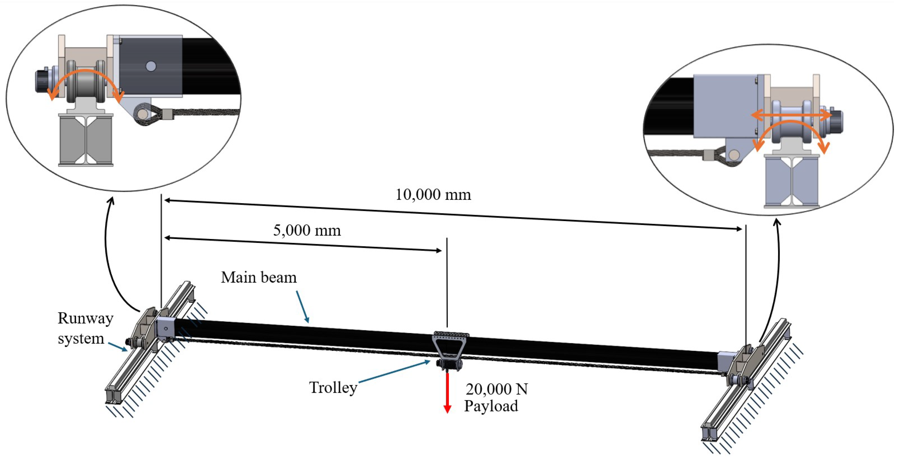
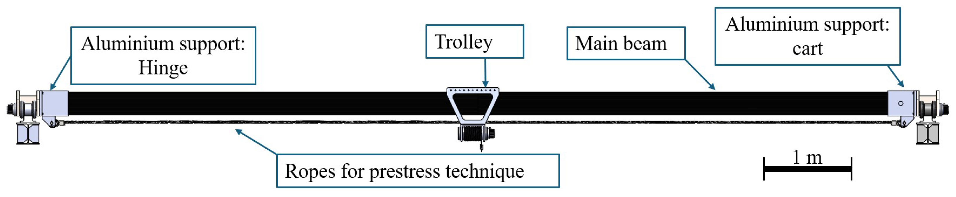
2. Description of the Overhead Crane

The overhead crane is a type of crane designed to efficiently lift and transport heavy loads within an industrial environment. It is composed of the following:
  • A bridge structure that spans the width of the area where the crane operates. This element is typically a beam; it supports the runway system and provides a stable platform for the movement of the hoist and trolley.
  • A runway system described as parallel steel beams secured to the building structure. This system ensures that the crane can move smoothly and safely along its designated path.
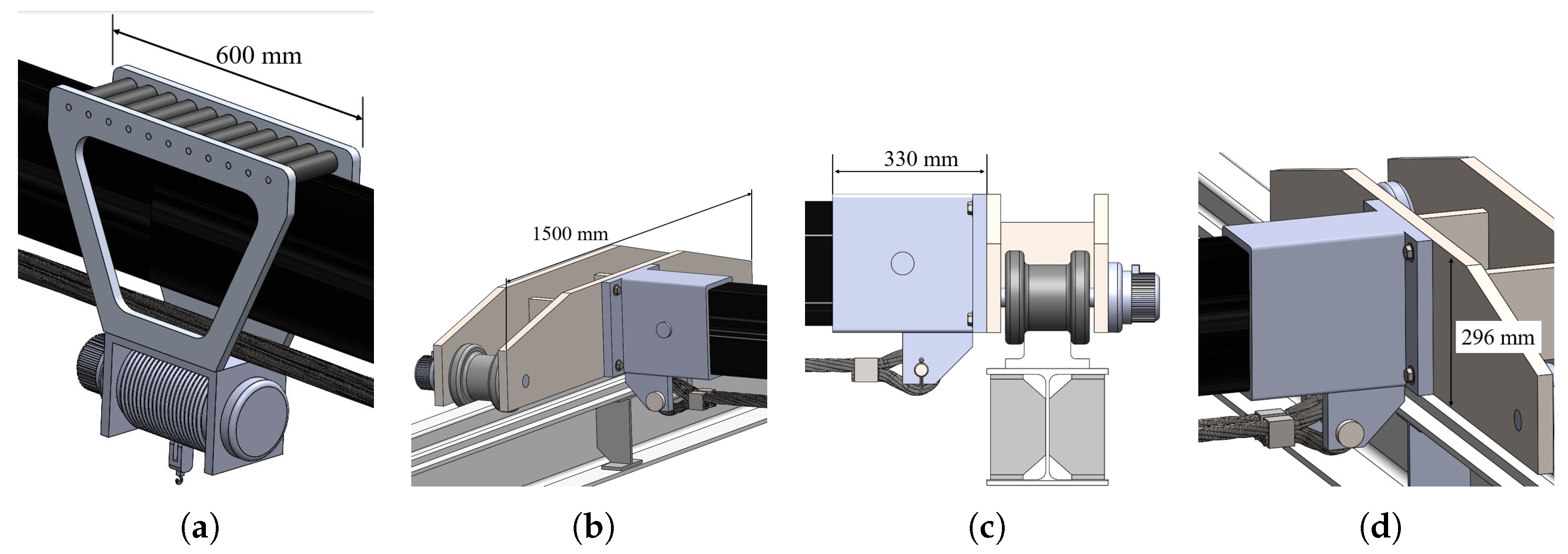
  • End trucks mounted on either end of the bridge; they house the wheels or rollers that enable the crane to travel along the runway beams.
  • The hoist assembly responsible for lifting and lowering loads. It consists of a motorized hoist unit mounted on the bridge, connected to a lifting mechanism.
  • A trolley mounted on the bridge. It moves horizontally along the length of the bridge, and it provides lateral movement for positioning the hoist assembly precisely within the working area.
The main dimension of such a crane is the length of the bridge, which is equal to 10 m. The payload is placed in the middle of the crane, which is the most critical position, and it weighs 20,000 N (≈2000 kg), as shown in Figure 1; the weight of the applied load takes into consideration the dynamic effects induced by the movement of the load itself, which can be estimated analytically [21] or experimentally [22]. Also, a fatigue life of around 50,000 cycles has been estimated, as already seen for other components in the literature [23]. Furthermore, the idea is to apply the precompression technique, also called the prestress or prestrain method, to the beam: with this technique, a structure is subjected to external loads that produce opposite, internal stresses with respect to the ones in exercise [24,25] in order to have a lower average stress along the component. The described methodology is typically applied in civil engineering, primarily because concrete, the main material used in this field, has good mechanical properties in compression but low tensile strength. However, the use of this technique for materials other than concrete has not been widely explored in the literature, likely due to limited knowledge, research, and the technological challenges associated with the methodology itself. Despite this, its advantages are numerous: by adopting the precompression method, the beam’s load-bearing capacity increases, allowing for thinner and longer spans, which leads to more efficient use of materials and cost savings in both materials and construction. Additionally, it offers better crack management, and lower stress enables greater design versatility, such as the ability to create more complex and visually appealing structures. For this reason, a prestressing force of 100,000 N has been applied to the bridge structure. The process of selecting the precompression value has been conducted through multiple iterations, aiming to find a balance between reducing vertical displacement and increasing stress, as reported in [26]. Based on the described boundary conditions, the equations of the elastic line [27] can be applied to analyze this crane. The main constraint for this type of crane, as defined by standards [28], is the maximum allowable vertical displacement. The regulations specify that the ratio of maximum vertical displacement to span length must not exceed 1/450 to prevent trolley rolling. This means that any solution must result in a maximum vertical displacement of less than 22 mm.

3. Design Methodology

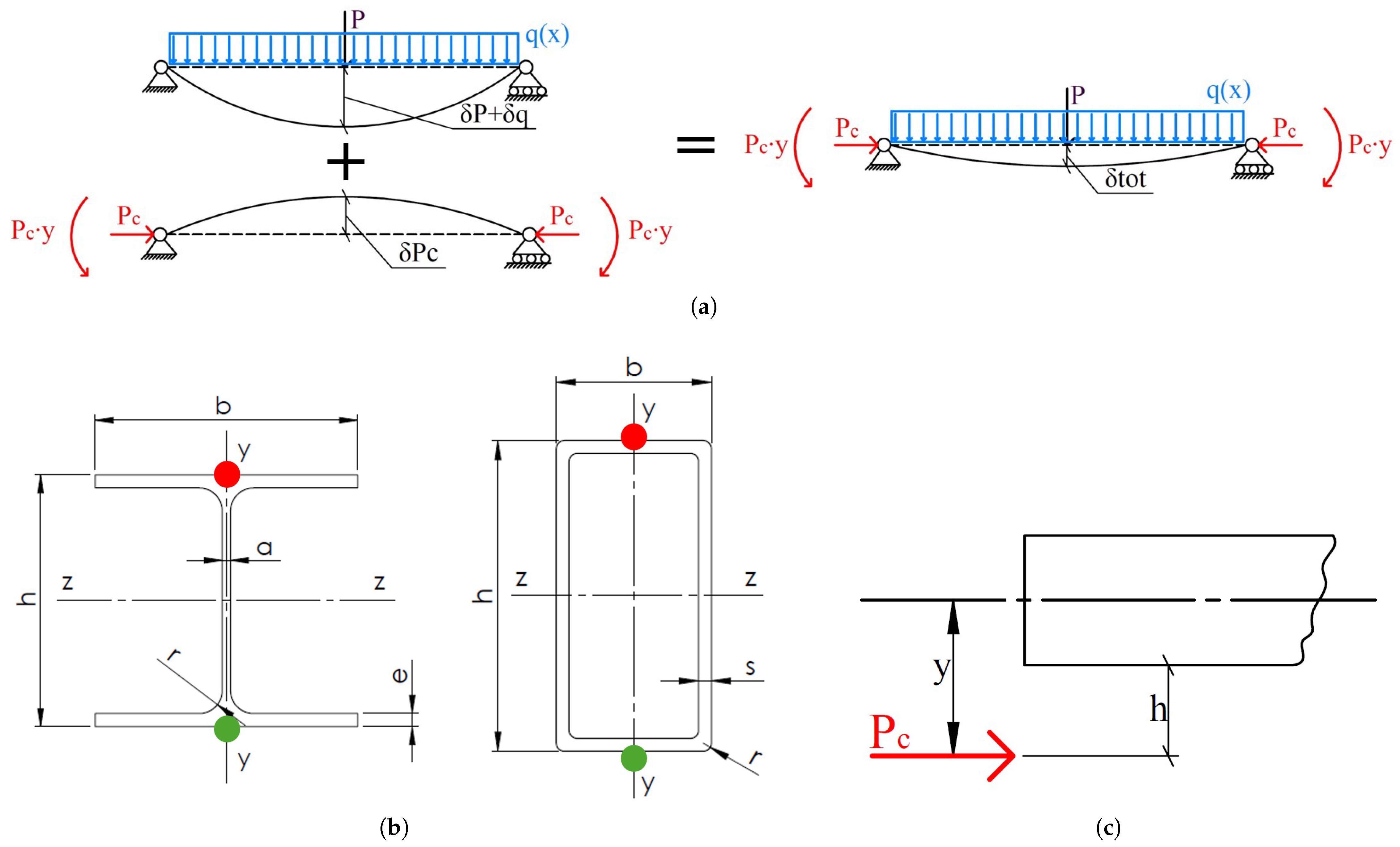
3.1. Analytical Design Theory

3.1.1. Evaluation of Stress and Displacement

The model used to represent the problem under study consists of a beam with a hinge at one end and a cart at the other. The rotation of both constraints is replicated in reality by the contact between the rail system and the wheels of the end truck, while the allowable translation of the cart is provided by the greater length of the wheels—only on one end truck of the overhead crane—relative to the thickness of the rail system. This structure is influenced by three factors: the weight of the girder itself, the load to be lifted, and the force that causes the prestress. The prestress (or prestrain) methodology involves applying a deflection to the beam that opposes the deflection caused by the weight of the structure and the external payload. One possible solution is to apply an external load that generates internal stresses opposite to those induced by the aforementioned factors. This external load can be implemented in various ways; one of the simplest solutions is to attach steel ropes to the lower part of the structure, creating a uniform bending moment along the entire boom. This vertical displacement counteracts the deflection caused by the applied load. By reducing deflections, the internal stresses are also reduced. With lower internal stresses, it is possible for booms with reduced geometry to withstand the applied loads while remaining within the limits set by the standards. To illustrate the methodology, Figure 2a shows where the loads are applied: in this configuration, the precompression force P c is applied at a distance y from the centreline of the beam, as shown in Figure 2c, producing a constant bending moment of P c · y .
Considering that P is the force due to the lifted weight, q ( x ) is the distributed load due to the weight of the beam, L is its length, E is the Young’s modulus of the material, and J is the moment of inertia of the boom’s cross-section, δ t o t ( x ) represents the vertical displacement at position x imposed by all the effects, as defined in Equation (1):
δ t o t ( x ) = δ q ( x ) + δ P ( x ) + δ P c ( x ) = 1 E J ( q 24 x 4 P + q L 12 x 3 + P c y 2 x 2 + ( P L 2 16 + q L 3 24 P c y L 2 ) x )
To evaluate the maximum vertical displacement of the beam, x must be replaced with L / 2 . Additionally, by defining h as the height of the boom and A as the cross-sectional area, the maximum stress acting at position x of the structure can be calculated. The top position is indicated by a red dot in Figure 2b, and the bottom position by a green dot:
σ ( x ) t o p = ( q 2 x 2 + P + q L 2 x P c y ) h 2 J P c A
σ ( x ) b o t = ( q 2 x 2 P + q L 2 x + P c y ) h 2 J P c A
Here too, to determine the maximum vertical displacement of the beam, x must be replaced with L / 2 . Equations (2) and (3) refer to the stresses at the two points shown in Figure 2.

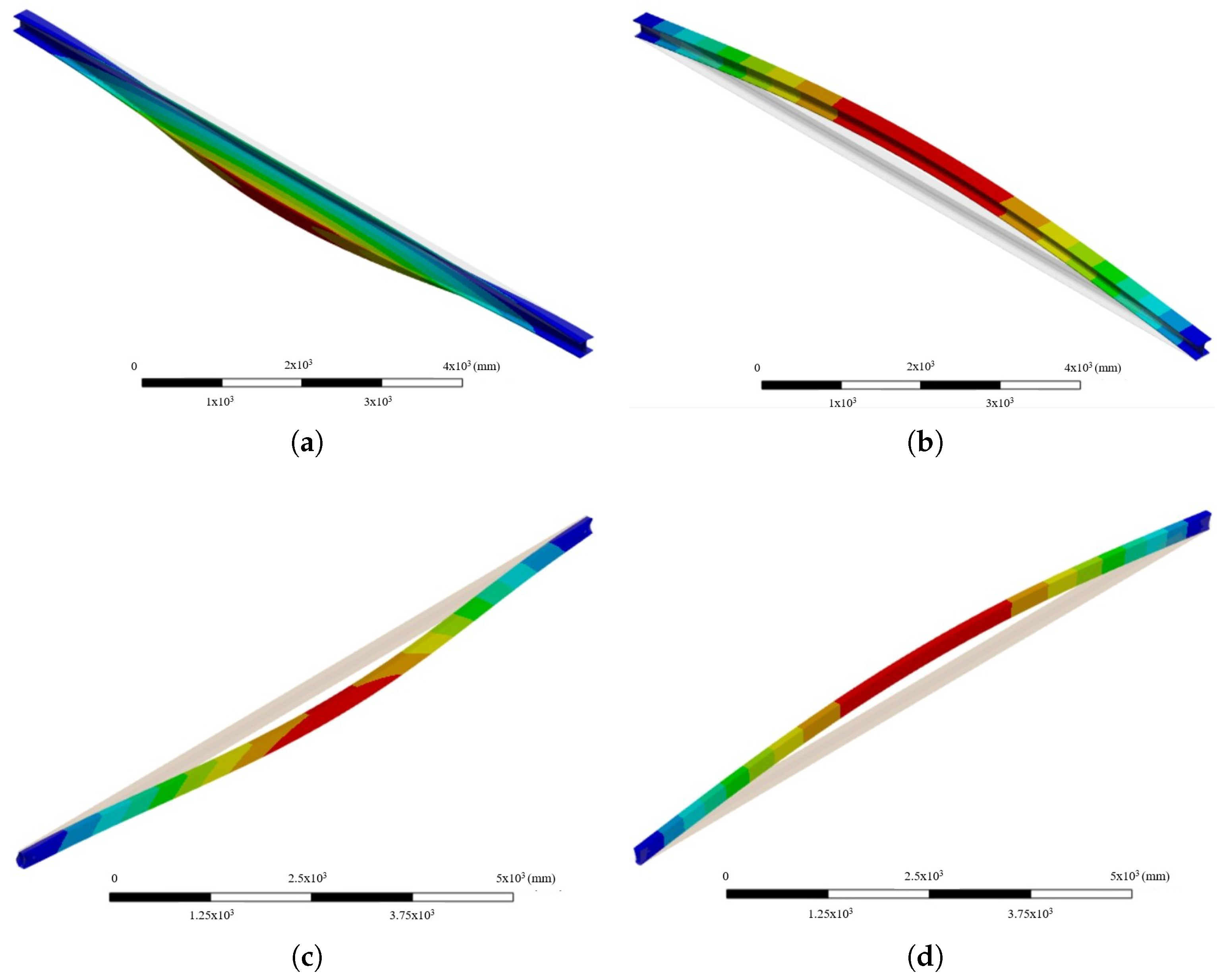
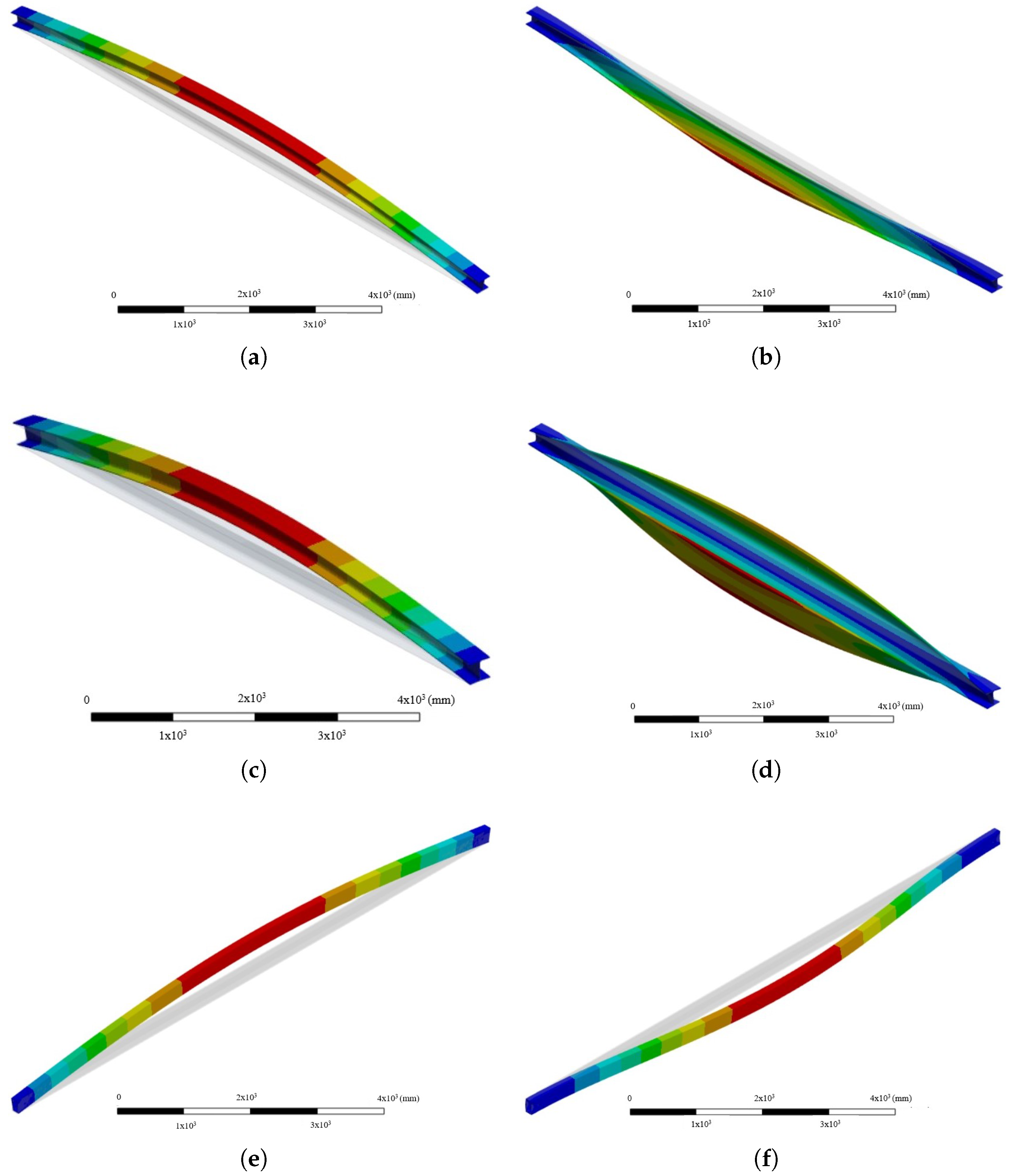
3.1.2. Buckling Analysis

The phenomenon of buckling manifests as lateral deformations in structural elements subjected to compressive forces. In the context of steel structures, where thinness is common, buckling assumes particular significance. According to elastic stability theory, Equation (4) defines P c r , the critical load at which a perfectly elastic component begins to exhibit non-axial deformations:
P c r = π 2 E J L 0 2
where E is Young’s modulus of the material, J is the minimum moment of inertia of the section, and L 0 is the length of free vertical displacement, which depends on how the beam is constrained. In this scenario, L 0 = L . Equation (4) assumes that the load is perfectly applied at the centre of the section. However, in reality, this is not achievable. Moreover, accidental inhomogeneities within the material or pre-existing deformations in the fibres may result in a beam that is not perfectly straight. These effects are known as second-order effects [29], and to account for them, the criteria in Equation (5) must be satisfied:
P a P c r , m + M e q M u ( 1 θ ) 1 w h e r e θ = P a P c r , m
where P a is the axial failure force in the presence of a primary bending moment, P c r , m is the buckling load at failure in the absence of a primary bending moment, M e q is the equivalent bending moment along with the axial force, and M u is the ultimate bending moment at failure without axial force. To define P c r , m , Equation (6) must be used:
P c r , m = χ A f y γ M 1 w h e r e χ = 1 ϕ + ϕ 2 + λ ¯ 2 1
where A is the cross-sectional area, f y is the material strength, γ M 1 is the material safety factor, and χ is the reduction coefficient accounting for the buckling phenomenon. The factors ϕ and the non-dimensional slenderness ratio λ ¯ are described in Equation (7):
ϕ = 0.5 · [ 1 + α · ( λ ¯ 2 0.2 ) + λ ¯ 2 ] ; λ ¯ = λ λ 1 = A f y P c r w h e r e λ 1 = π E f y
where α accounts for imperfections and can take values of 0.13, 0.21, 0.34, 0.49, and 0.76 for buckling curves a 0 , a, b, c, and d (European design buckling curves), respectively [29,30]. The non-dimensional slenderness ratio λ ¯ is the ratio between the slenderness of the relevant buckling mode λ (in this scenario, along the x-axis in Figure 2) and a coefficient λ 1 , which depends on Young’s modulus E and the material strength f y . It should be noted that slenderness λ is the ratio between the critical length L 0 and the radius of gyration about the relevant axis. For the other terms in Equation (5), Equation (8) shows how to evaluate them:
M u = f y W p l γ M 1 ; M e q = C m · | M B | w h e r e C m = 0.6 0.4 ( M A / M B ) 0.4
where M A and M B are the moments at the ends of the boom, and their ratio is considered negative for single curvature bending and positive for double curvature bending. The coefficient W p l represents the plastic section modulus of the beam and is defined in Equations (9) and (10), derived from the dimensions shown in Figure 2b:
W p l , H E A = 2 a h 2 8 + e ( b a ) h e 2 + 2 r 2 h 2 e r 2 2 π r 2 4 h 2 e r + 4 r 3 π
W p l , r e c t a n g u l a r = b h 2 4 ( b 2 t ) h 2 t 2
Another type of instability that can occur is flexural–torsional buckling, which can lead to the failure of thin-walled structural elements made of either metallic (isotropic) material [31] or composite (orthotropic) material [32]. This instability causes the element to twist out of the critical plane and bend laterally. Both generalised [33,34] and specific [35] solutions to analyze this condition are available in the literature, as this instability tends to occur when elements have low bending and flexural–torsional rigidity compared to the rigidity in the load plane. One method to prevent this is by using sections that are resistant to buckling. For instance, closed sections have greater torsional stiffness ( G J ) and bending stiffness ( E I y , where I y is the lesser moment of inertia of the section with respect to the y-axis in Figure 2b) compared to open I-sections. They are less prone to flexural–torsional buckling. To determine the critical load that could lead to flexural–torsional buckling failure of the boom [36], the following parameters must be estimated:
J = 42 b e 3 + h a 3 3 ; I w = e h 2 b 3 24 ; r 1 2 = ( I z + I y ) / A + y 0 2
In Equation (11), J is the torsional constant of the section, where the section’s geometry is shown in Figure 2b, I w denotes the warping constant of the section, and y 0 is the distance of the applied load from the centroidal axis (z-axis in Figure 2b) of the beam. With these parameters, it is possible to evaluate the flexural ( P z and P y ) and torsional ( P x ) buckling resistance.
P z = π 2 E I z L 2 ; P y = π 2 E I y L 2 ; P x = G J + π 2 E I w L 2 / r 1 2
Using the values from Equation (12), the beam’s uniform bending buckling resistance M y x and the bending moment M z can be calculated through Equation (13), which can be approximated under the condition that the compressive load P is less than P z :
M z M 1 P / P z ; M y x = r 1 P y P x
Finally, the compressive load P for the studied beam can be evaluated using Equation (14):
M M y x = 1 P P z · 1 P P y · 1 P P x
In particular, for the buckling analysis of composite materials, the FEA-based modelling approach and methodology adopted are the same as those used in previous studies [37,38,39].

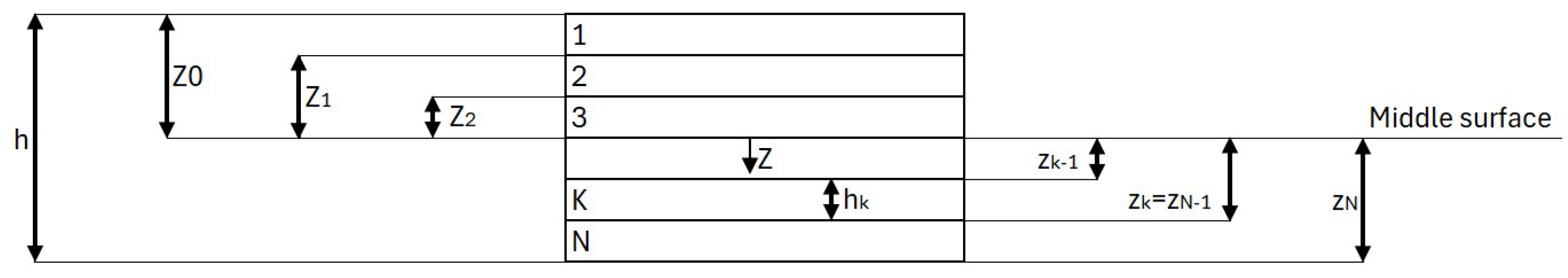
3.2. Description of the Adopted Material

This type of structure is typically made of steel. In this paper, a solution using steel S355JR, as defined in the UNI EN 10027-1 standard [40], has been studied in order to analyze the traditional configuration both with and without the prestress method. Another configuration made of aluminium 6061-T6 has also been examined, and the properties of these isotropic materials are presented in Table 1.
The third proposed solution was designed using a carbon fibre-reinforced polymer. This material was chosen due to its exceptional mechanical properties, as demonstrated in Ashby’s diagrams [41], where stiffness and density play a crucial role for this component. While it would be possible to use natural composite materials, as has been carried out in previous research [42,43], the main focus of this study is weight reduction, so a higher-performance material was preferred. Specifically, the carbon fibre selected for this study is M 50 J [44], and the matrix is epoxy resin S X 10 [45]. Their mechanical properties are shown in Table 2. The properties of the ply are shown in Table 3.
Based on the fibre and matrix information, and assuming the fibres are aligned along the main longitudinal direction, the theory of micromechanics of orthotropic plates [46] was used to calculate parameters such as density, Poisson’s ratio, etc. (Equations (15) and (16)):
ρ = ρ f V f + ρ m V m ; ν 12 ( = ν 13 ) = ν f V f + ν m V m ; E 1 = E f V f + E m V m ;
E 2 ( E 3 ) = E f E m V m E f + V f E m ; X T = σ f t V f ; Y C = σ m c [ 1 + ( V f V f ) ( 1 E m E f ) ]
To determine the longitudinal compressive strength ( X C ), shear strength (S), and transverse tensile strength ( Y T ), values from [44] were used.
Using the proposed geometry of the component and the percentage of ply types, it is possible to apply classical composite theory for two-dimensional laminates [46] for an initial analysis. By introducing a reference system with the first two axes on the lamina and neglecting the deformation ϵ 3 (which is orthogonal to the lamina plane), the deformations for a special orthotropic lamina can be evaluated using Equation (17). The S i j components of the compliance matrix S are calculated based on the elastic constants of the lamina (Table 3), with a density ρ of 1608 kg/m3, a Poisson’s ratio ν 12 of 0.3, and a carbon fibre percentage V f % of 60%.
ϵ 1 ϵ 2 γ 12 = S 11 S 12 0 S 12 S 22 0 0 0 S 66 σ 1 σ 2 τ 12 ; S 11 = 1 E 1 ; S 22 = 1 E 2 ; S 12 = ν 12 E 1 = ν 21 E 2 ; S 66 = 1 G 12
To calculate stresses from deformations, the stiffness matrix Q, which is the inverse of the compliance matrix, must be used. These formulations can also be applied to laminates with fibres aligned along the main axis. However, if there is a relative angle θ , it is necessary to use the rotation matrix T, where c = cos θ and s = sin θ , as described in Equation (18).
σ 1 σ 2 τ 12 = Q 11 Q 12 0 Q 12 Q 22 0 0 0 Q 66 ϵ 1 ϵ 2 γ 12 T = c 2 s 2 2 s c s 2 c 2 2 s c s c s c c 2 s 2
To adjust the compliance matrix S and the stiffness matrix Q for the new direction, the transformations in Equation (19) must be followed:
[ S ¯ ] = [ T ] T [ S ] [ T ] [ Q ¯ ] = [ T ] T [ Q ] [ T ]
Additionally, the expression used to calculate stresses in a generic lamina is given in Equation (20):
σ x σ y τ x y = Q 11 ¯ Q 12 ¯ Q 16 ¯ Q 12 ¯ Q 22 ¯ Q 26 ¯ Q 16 ¯ Q 26 ¯ Q 66 ¯ ϵ x ϵ y γ x y
At this point, the forces and moments can be evaluated using the following equation:
N x N y N x y M x M y M x y = A 11 A 12 A 16 B 11 B 12 B 16 A 12 A 22 A 26 B 12 B 22 B 26 A 16 A 26 A 66 B 16 B 26 B 66 B 11 B 12 B 16 D 11 D 12 D 16 B 12 B 22 B 26 D 12 D 22 D 26 B 16 B 26 B 66 D 16 D 26 D 66 ϵ x 0 ϵ y 0 γ x y 0 k x k y k x y
where ϵ i 0 and k i j represent the deformations and curvatures of the laminate in the principal directions, respectively. Equation (21) can also be written as:
N M = A B B D ϵ 0 k
The components of the so-called ABBD matrix shown in Equation (22) can be described by Equation (23):
A i j = k = 1 N ( Q ¯ i j ) k ( z k z k 1 ) ; B i j = 1 2 k = 1 N ( Q ¯ i j ) k ( z k 2 z k 1 2 ) ; D i j = 1 3 k = 1 N ( Q ¯ i j ) k ( z k 3 z k 1 3 )
where i represents the number of rows of the matrix, j the columns of the matrix, and k the number of layers. Thanks to the choice of a balanced and symmetrical laminate, the components of the B-matrix, such as A 16 and A 26 , are zero. Furthermore, a local reference system has been defined to evaluate the stresses; the x-axis has been chosen as the one longitudinal to the bridge (see Figure 2a), and the XY plane is tangent to the surface of the component. By setting the total number of laminas N and the thickness h of the composite, the coordinate system shown in Figure 3 can be defined:
The deformations and curvature of the laminate can be calculated analytically by multiplying the inverse of the ABBD matrix with the matrix of forces and moments, as evaluated using Equation (24):
ϵ 0 k = A B B D N M
Through the inverse of the ABBD matrix, it is also possible to evaluate the equivalent membrane elastic constants of the entire laminate. If the chosen laminate is symmetrical and balanced, this results in equal deformations throughout the laminate and zero curvature. These equivalent membrane elastic constants are defined in Equation (25):
E X m = 1 A 11 · h ; E Y m = 1 A 22 · h ; G X Y m = 1 A 33 · h ; ν X Y m = A 12 A 11 ; ν Y X m = A 12 A 22
where h is the thickness of the laminate, and the other terms are the values within the inverse A-matrix. The results of Equation (25) for the composite solution under study are shown in Table 4:
Thanks to the deformation and curvature values from Equations (2) and (3), and the thickness of the laminate, it was possible to use Equation (26) to obtain the local stresses along the directions for each lamina composing the entire laminate.
ϵ x ϵ y γ x y = h A 1 σ f 0 τ t σ x σ y τ x y = Q ¯ ϵ x ϵ y γ x y σ 1 σ 2 τ 12 = T σ x σ y τ x y
By connecting the local and lamina reference systems, and considering the maximum bending stress, the maximum shear stress (obtained based on the geometry of the component and the boundary conditions described in Section 3.1), the Tsai–Hill criterion (Equation (27)) can be applied to determine the factor of safety (FOS) for a composite material. This is based on the resistance values shown in Table 3, as described in the literature [47]:
F I = σ 1 2 X 1 2 σ 1 σ 2 X 1 2 + σ 2 2 X 2 2 + τ 12 2 S 2 ; F O S = 1 F I
where X 1 represents X T if σ 1 > 0 or X C if σ 1 < 0 , while X 2 represents Y T if σ 2 > 0 or Y C if σ 2 < 0 . To determine if the ply theoretically reaches failure, the FOS should be less than 1. After several analytical computations, a square profile in composite material with a thickness of 11 mm was designed, as shown in Table 5 and Table 6, using 22 plies with different orientations. Specifically, 35% of the plies have an orientation of 5°, 35% have an orientation of −5°, 10% have an orientation of 45°, 10% have an orientation of −45°, and 10% have an orientation of 90°. These angles were chosen considering a filament winding process, specifically the possibility of using only helical winding (the filament winding process for angles from 5° to 85°) or maximum hoop winding (for orientations from 85° to 90°). Although the best orientation for bending loads is 0°, the process cannot easily lay fibres exactly along the length of a component [48], so polar winding (for angles from 0° to 5°) was avoided to prevent significant impacts on productivity.

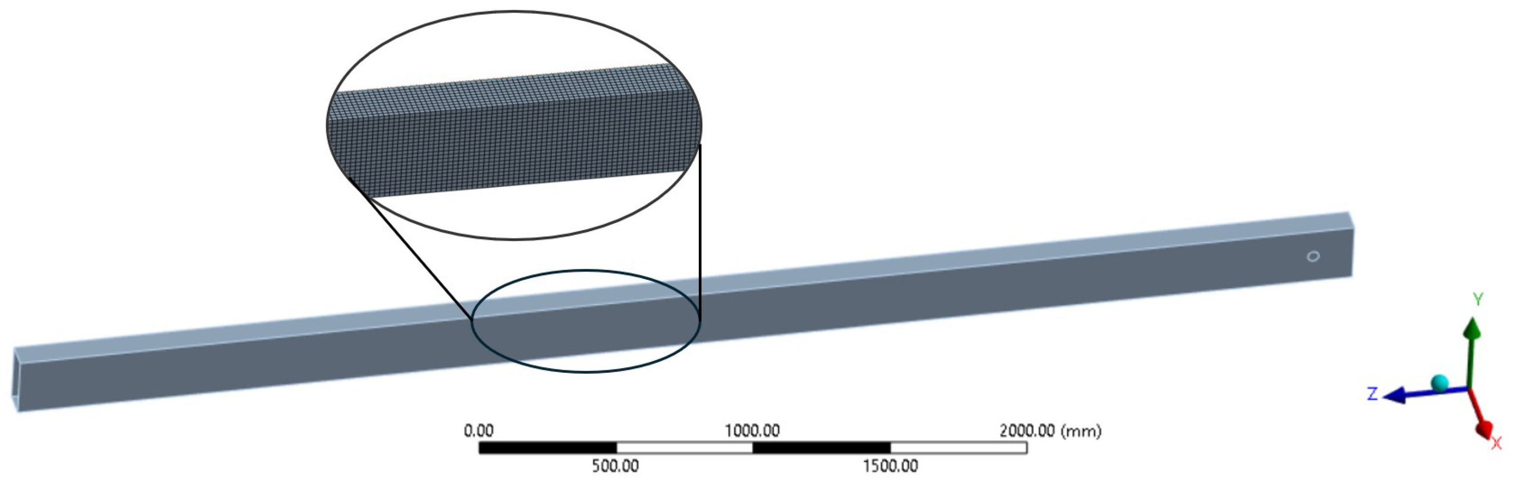
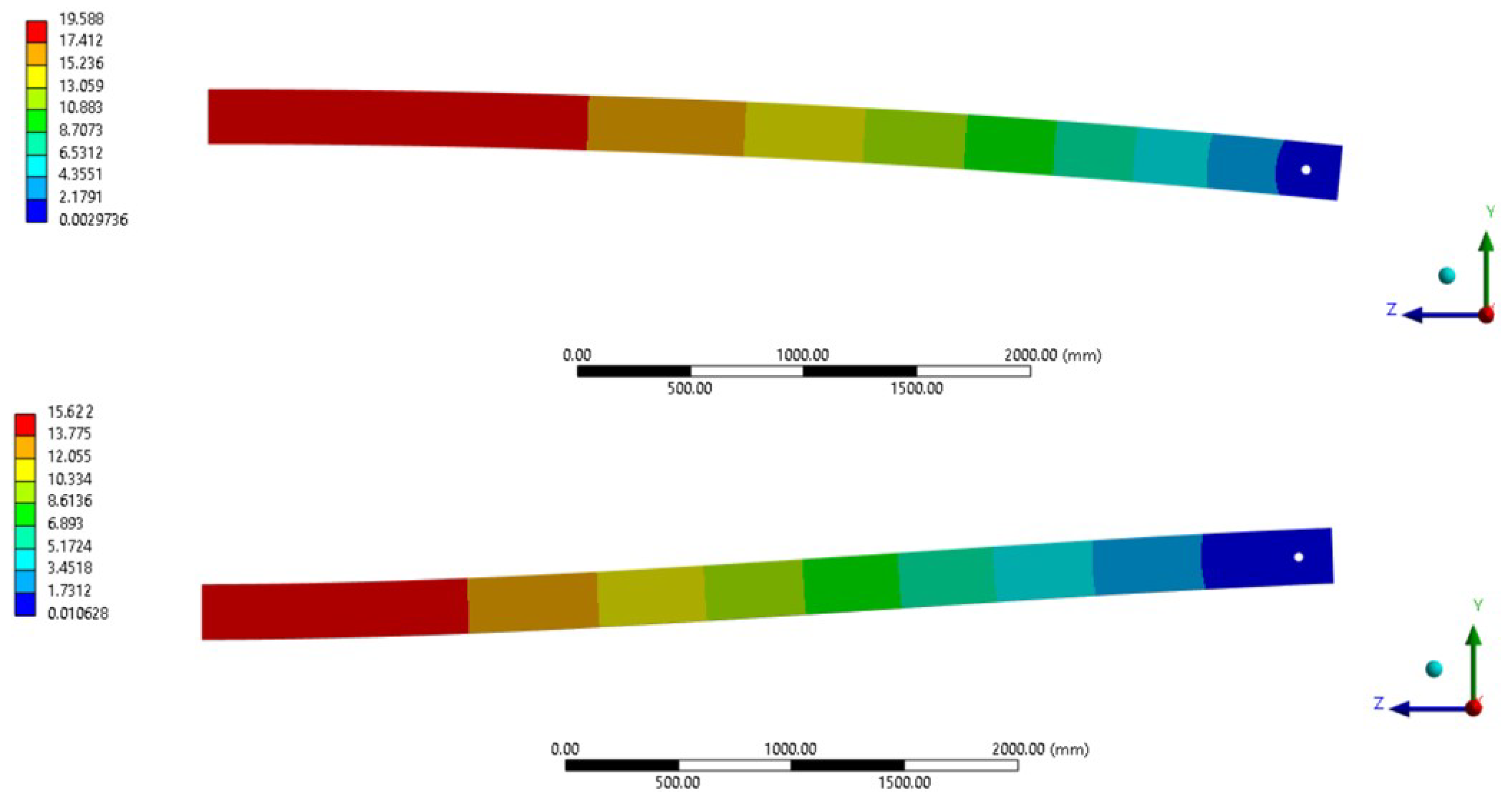
3.3. Design and FEM Analysis

The design of the bridge structure was divided into two phases: the first involved an analytical evaluation of the optimized geometry, while in the second phase, a solid model was implemented using Ansys®and Solidworks®to validate the analytical computations. Three solutions were developed in this paper: one in S355JR and another in Al 6061-T6 with a section geometry defined as an HEA beam described by UNI 5397-78, while the last solution was made from CFRP with a tubular constant section. The analytical formulations differed based on the material behaviour: for the critical load, the formulations derived from the literature were applied to isotropic materials, while for the composite solution, the equations described in Section 3.2 were adopted. For the evaluation of maximum displacement, the equation of the elastic line was applied for all solutions. For the CFRP solution, the Young’s modulus used was E X m from Table 4. The mesh consisted of quadratic solid elements, with approximately 85,000 nodes and 42,000 elements for the boom study. An example of the mesh is shown in Figure 4. As described in Section 3.1, the bridge structure is constrained by a hinge and a roller at the edges, with a concentrated force of 20,000 N (equivalent to a weight of about 2000 kg) applied in the middle, gravity acting on the structure’s weight, and precompression simulated by applying forces to the ends of the girder along with a moment resulting from the distance between the ropes and the beam’s centreline. Figure 5 shows the FEM model of the CFRP prestressed configuration. Due to the system’s symmetry, only half of the beam was modelled to reduce computation time.
The precompression load was set to 100,000 N, and the applied moment varied for each solution depending on the geometry. The main idea was to define this value as the product of P c and the sum of half the boom height plus 80 mm, which is the imposed distance between the bottom of the bridge structure and the rope, referred to as h in Figure 2c. This value was chosen to minimize the overall dimensions. Table 5 shows the vertical displacements of the non-prestressed configurations analyzed. Without the pre-strain method, the geometry of the sections in the obtained configuration had higher values than those shown in Table 6, which shows the vertical displacements of the prestressed solutions. All these displacements never exceeded 20 mm, meaning the vertical displacement/span ratio was 20/10,000 = 1/500, which is within the limits imposed by the standards. When the precompression technique was applied, the section (and therefore the weight) was smaller, with similar displacements.
To fully understand the improvement in weight, Table 7 provides a comparison of the main beam’s weight in all configurations and the payload. The payload is defined in [kg], and the weight reduction can be observed in the last column, comparing the prestressed and non-prestressed configurations.
Regarding the global buckling analysis, Figure 6 shows the first two modes of instability for the solutions. The S355JR and 6061-T6 configurations exhibited similar buckling modes due to their similar geometries, as shown in Figure 6a,b. For the CFRP solution, Figure 6c,d show its first two buckling modes. The numerical results reported a safety factor η concerning buckling phenomena of 14.03 for the steel configuration, 7.33 for the aluminium one, and 10.07 for the composite solution’s first buckling mode. Local buckling was also considered, as described in the literature [49]. The safety factors for the steel solution were 5.46, for the aluminium 4.09, and for the CFRP configuration 6.41.
For the modal analysis, Figure 7 shows the first two vibration modes for each prestressed configuration. These analyses were carried out due to the system’s dynamics, which involved different electric motors for the lifting phase on the trolley and the movement phase on the end trucks. As can be seen, the high Young’s modulus and low density of the CFRP result in higher resonance frequencies than the other solutions. In contrast, the high density and lower moment of inertia of the steel, compared to the aluminium configuration, resulted in the lowest resonance frequencies.
Regarding the fatigue life of the three solutions, due to the adoption of the pre-compression method, which reduces the stress within the bridge structure, both the analytical and numerical results confirm that the highest stress, with the payload in the prestressed configuration, was 56 MPa for the steel solution. This is far below the material’s fatigue limit [50]. For aluminium, the maximum computed stress was less than 40 MPa, and even in this case, the estimated life at such stress [51] exceeds the number of cycles the structure is designed to withstand. For the CFRP solution, the highest stress was around 90 MPa, but [52,53] indicate that for an average CFRP material, this stress does not lead to failure over the estimated life cycle described in Section 2.

4. Construction Methods

The innovative solution proposed, as described in Section 3.3, involves a CFRP beam with a hollow section, produced using the filament winding process [54]. Figure 8 shows the actual solution:
Focusing on the details of this configuration, the components designed include the trolley on the bridge, the runway system, and the connection between the runway system and the bridge structure. As seen in Figure 9a, the trolley used to lift the load is composed of two aluminium plates, each weighing 5 kg, which connect eleven rollers that allow the winch to move along the overhead crane. The rollers are made of steel and Vulkollan®polyurethane rubber [55], each weighing 0.3 kg, in order to prevent wear on the composite surface. The total mass of this trolley is 13.3 kg, excluding the motorized winch, which is lighter than the average trolley for these boundary conditions, typically around 20 kg.
Figure 9b shows one side of the runway system. The hinge constraint is defined by the allowable rotation of the trolley wheel and its guide, which can be seen more clearly in Figure 9c. Horizontal displacement is prevented by the connection between the CFRP boom and the lateral trolley. This connection is made using a safety pin and adhesive, as described in the literature [56], between the aluminium support and the beam. This connection is absent on the other side of the crane, where the roller constraint is located, as shown in Figure 9d. The aluminium support weighs approximately 10.2 kg.
Precompression of the girder is achieved through steel ropes, connected to the aluminium support with a pin held in place by a cotter pin. The two ropes have a metal core, with a diameter of 14 mm and a 7 × 19/133 wire configuration, providing an ultimate tensile load of 124,000 N each. With the precompression load, P c , equal to 100,000 N and applied through a commercial rope tensioner, there is a safety factor of 2.48. The ropes weigh 0.82 kg/m, making each one 8.2 kg. Considering the mass of the non-prestressed steel configuration, these components do not significantly affect the overall weight of the structure.

5. Results

Using the geometry of the proposed solution and FEM software, the masses of the overhead crane booms have been determined.
Considering the different materials, without the use of the prestressed beam concept, it was evaluated that the weight of the aluminium component is 56.6% of the traditional solution, and the value is reduced to about 19.9% for the composite material component, as shown in Table 8. Focusing on the prestressed configurations, the weight of the aluminium solution is reduced to 50.7% compared to the prestressed steel configuration, and for the composite, it is even lower at 20.3%, as shown in Table 9.
It is also interesting to observe not only the weight reduction due to the use of different materials, but also to compare the same material with and without the prestressing method to assess the impact of this concept alone. To analyze this, Equation (28) has been used:
p P r e / N o n P r e % = W P r e s t r e s s e d m a t e r i a l W N o n P r e s t r e s s e d m a t e r i a l · 100 [ % ]
where W P r e s t r e s s e d m a t e r i a l is the weight of the prestressed solution of the material analyzed, and W N o n P r e s t r e s s e d m a t e r i a l is the weight of the non-prestressed configuration of the material analyzed. The value p P r e / N o n P r e % provides an indication of the weight reduction achieved by the prestressing methodology alone. The prestressed S355JR solution is 79.0% (=599.32/758.66) of the non-prestressed version. For the aluminium, it is 70.8% (303.83/429.22), while for the composite, the result is around 80.4% (121.69/151.40).
Examining the combination of different materials and the prestressing method, the weight of the prestressed aluminium configuration is 40% (=303.83/758.66) of the traditional solution, with the value further reduced to 16% (=121.69/758.66) for the composite component, as shown in Figure 10.
These results show that using innovative materials can lead to significant weight reductions, and the weight loss can be even greater when the prestressing methodology is applied. Another notable observation is that the prestressing method has a greater effect on structures where the material used has lower stiffness. The primary reason is that the most significant constraint in overhead cranes is the maximum vertical displacement, which is directly related to the stiffness.

6. Conclusions

The work outlines a comprehensive process aimed at reducing the weight of an overhead crane structure by employing innovative materials and the prestress method. It begins by detailing the analytical criteria and selected materials, followed by extensive numerical and analytical analyses for each solution. The design has been developed to cover many aspects of the studied structure. By performing static structural, buckling, fatigue, and modal analyses for each configuration, significant results have been achieved with the goal of weight reduction.
The solutions bring important innovations to the literature:
  • The prestress methodology can be applied to the design of heavy industrial structures, offering benefits for lightweight design.
  • The implementation of innovative materials, such as composite materials, can be adopted for these specific structures, achieving results similar to steel in terms of deflection but with a much lower density, and therefore, lower mass.
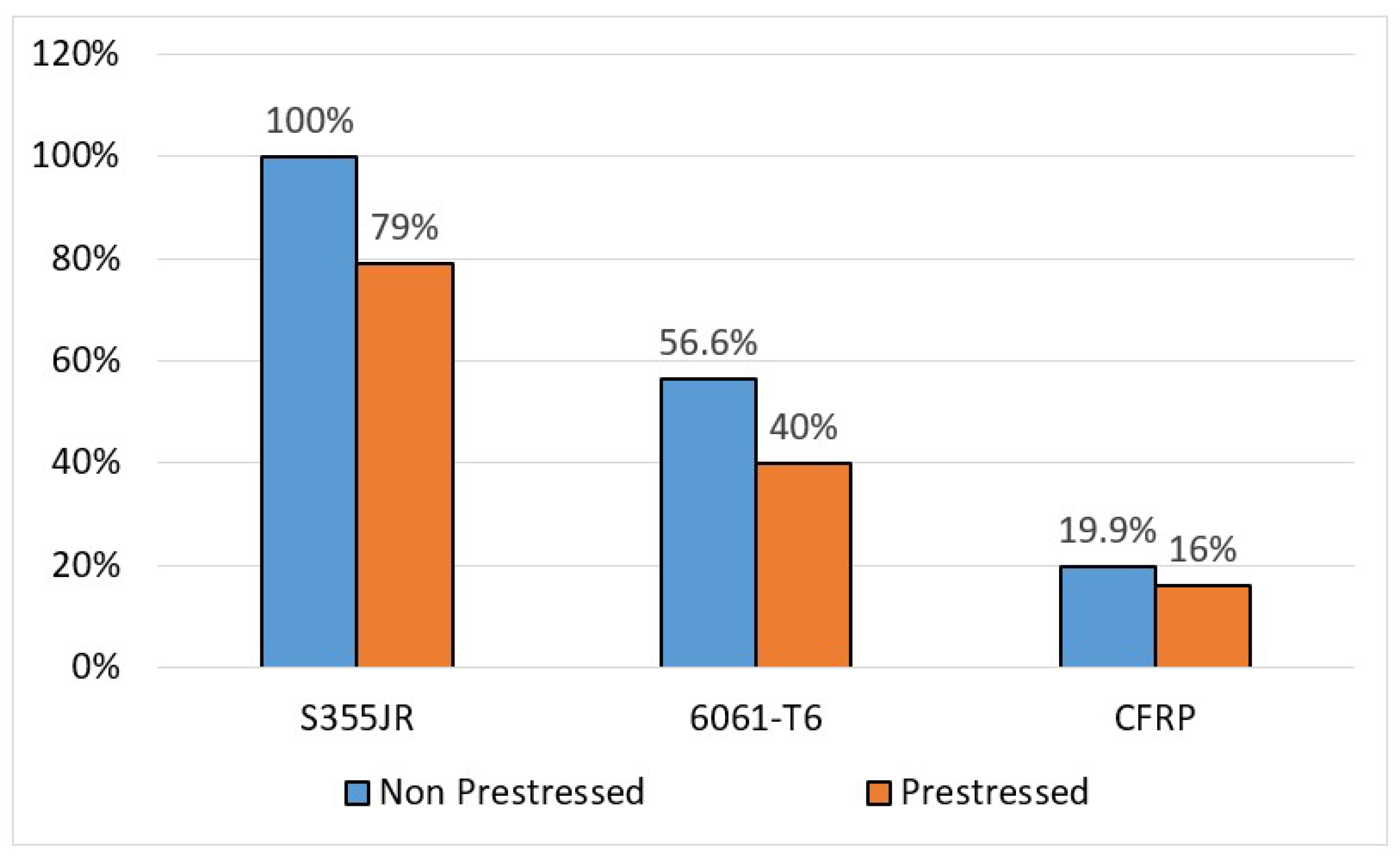
  • The combination of the two methodologies can lead to a significant reduction in weight. For instance, when comparing the non-prestressed steel solution with the composite prestressed configuration, the latter weighs only 16% of the former.
The results achieved in weight reduction carry noteworthy implications:
  • Electric motors powering the overhead crane require less effort.
  • The lighter structure reduces inertia forces.
  • The brake systems also benefit.
  • The building itself, where the overhead crane is located, experiences less stress.
  • The installation of the analyzed structure can be carried out with easier procedures compared to a heavier configuration.
  • The successful implementation of these methodologies opens up possibilities for their application in other sectors of construction machinery. For instance, similar techniques could be adapted for different types of cranes, facilitating further advancements in the field.
It should be noted that the CFRP configuration is suitable for environments where temperature is not an issue, due to its thermal properties. This, along with other factors that could decrease long-term performance, will be the subject of future research. Additionally, this composite material is far more expensive than traditional materials, but the overall cost of the assembly has been considered, as previously discussed in the literature [57].

Future Developments

To validate the numerical and analytical results, the research is ongoing, and some experimental tests with small-scale prototypes are scheduled. Furthermore, a cost comparison analysis will be carried out to provide greater insight into the economic aspects of the structure.

Author Contributions

Conceptualization, L.S.; methodology, L.S. and I.T.; software, L.S. and I.T.; validation, L.S. and I.T.; formal analysis, L.S. and I.T.; investigation, L.S.; resources, L.S.; data curation, L.S.; writing—original draft preparation, L.S. and I.T.; writing—review and editing, L.S.; visualization, I.T.; supervision, L.S.; project administration, L.S.; funding acquisition, L.S. All authors have read and agreed to the published version of the manuscript.

Funding

This work was supported/financed by the European Union-NextGenerationEU (National Sustainable Mobility Center CN00000023, Italian Ministry of University and Research Decree n. 1033-17/06/2022, Spoke 11-Innovative Materials & Lightweighting). The opinions expressed are those of the authors only and should not be considered as representative of the European Union or the European Commission’s official position. Neither the European Union nor the European Commission can be held responsible for them.

Informed Consent Statement

Informed consent was obtained from all subjects involved in the study.

Data Availability Statement

The original contributions presented in the study are included in the article, further inquiries can be directed to the corresponding author.

Conflicts of Interest

The authors declare no conflicts of interest.

References

  1. Faruk, O.; Tjong, J.; Sain, M. (Eds.) Lightweight and Sustainable Materials for Automotive Applications; CRC Press: Boca Raton, FL, USA, 2017. [Google Scholar]
  2. Mallick, P.K. (Ed.) Materials, Design and Manufacturing for Lightweight Vehicles; Woodhead Publishing: Cambridge, UK, 2020. [Google Scholar]
  3. Solazzi, L.; Assi, A.; Ceresoli, F. New design concept for an excavator arms by using composite material. Appl. Compos. Mater. 2018, 25, 601–617. [Google Scholar] [CrossRef]
  4. Santos, J.; Gouveia, R.M.; Silva, F.J.G. Designing a new sustainable approach to the change for lightweight materials in structural components used in truck industry. J. Clean. Prod. 2017, 164, 115–123. [Google Scholar] [CrossRef]
  5. Solazzi, L.; Scalmana, R. New design concept for a lifting platform made of composite material. Appl. Compos. Mater. 2013, 20, 615–626. [Google Scholar] [CrossRef]
  6. Bonopera, M.; Chang, K.C.; Lee, Z.K. State-of-the-art review on determining prestress losses in prestressed concrete girders. Appl. Sci. 2020, 10, 7257. [Google Scholar] [CrossRef]
  7. You, Z. Displacement control of prestressed structures. Comput. Methods Appl. Mech. Eng. 1997, 144, 51–59. [Google Scholar] [CrossRef]
  8. Kaur, H.; Jaspal, S. A review on external prestressing in concrete. Int. Res. J. Eng. Technol. 2017, 4, 1801–1805. [Google Scholar]
  9. Li, Z.M.; Qiao, P. Buckling and postbuckling of anisotropic laminated cylindrical shells under combined external pressure and axial compression in thermal environments. Compos. Struct. 2015, 119, 709–726. [Google Scholar] [CrossRef]
  10. Kumar, D.; Marchi, M.; Alam, S.B.; Kavka, C.; Koutsawa, Y.; Rauchs, G.; Belouettar, S. Multi-criteria decision making under uncertainties in composite materials selection and design. Compos. Struct. 2022, 279, 114680. [Google Scholar] [CrossRef]
  11. Solazzi, L. Feasibility study of a very big crawler crane using composite materials. Compos. Part C Open Access 2024, 13, 100430. [Google Scholar] [CrossRef]
  12. Suvorov, V.; Vasilyev, R.; Melnikov, B.; Kuznetsov, I.; Bahrami, M.R. Weight Reduction of a Ship Crane Truss Structure Made of Composites. Appl. Sci. 2023, 13, 8916. [Google Scholar] [CrossRef]
  13. Gąska, D.; Haniszewski, T. Modelling studies on the use of aluminium alloys in lightweight load-carrying crane structures. Transp. Probl. 2016, 11, 13–20. [Google Scholar] [CrossRef]
  14. Gu, J.P.; Qin, Y.X.; Xia, Y.Y.; Jiao, Q.Q.; Gao, H.B.; Zhang, Y.Y.; Zhang, H. Research on dynamic characteristics of composite towering structure. Int. J. Appl. Mech. 2021, 13, 2150096. [Google Scholar] [CrossRef]
  15. Alkin, C.; Imrak, C.E.; Kocabas, H. Solid modeling and finite element analysis of an overhead crane bridge. Acta Polytech. 2005, 45, 61–67. [Google Scholar] [CrossRef] [PubMed]
  16. Savković, M.M.; Bulatović, R.R.; Gašić, M.M.; Pavlović, G.V. Stepanović, A.Z. Optimization of the box section of the main girder of the single-girder bridge crane by applying biologically inspired algorithms. Eng. Struct. 2017, 148, 452–465. [Google Scholar] [CrossRef]
  17. Yildirim, Ş.; Emir, E. A new approach for dynamic analysis of overhead crane systems under moving loads. In CONTROLO 2016, Proceedings of the 12th Portuguese Conference on Automatic Control, Guimarães, Portugal, 14–16 September 2016; Springer International Publishing: Cham, Switzerland, 2017. [Google Scholar]
  18. Oellerich, J. Fundamentals for the Dimensioning and Optimization of Prestressed Segmented Girders for Application in Bridge Crane Systems; KIT Scientific Publishing: Karlsruhe, Germany, 2022; p. 242. [Google Scholar]
  19. Oellerich, J.; Büscher, K.J. Application of Segmented and Prestressed Supporting Structures in Bridge Crane Systems: Potentials and Challenges. Appl. Syst. Innov. 2023, 6, 105. [Google Scholar] [CrossRef]
  20. Solazzi, L.; Nicola, D. Jib crane lightweighting through composite material and prestressing technique. Compos. Struct. 2024, 343, 118283. [Google Scholar] [CrossRef]
  21. Solazzi, L.; Incerti, G.; Petrogalli, C. Estimation of the Dynamic Effect in the Lifting Operations of a Boom Crane. In Proceedings of the 28th European Conference on Modelling and Simulation, Brescia, Italy, 27–30 May 2014; pp. 309–315. [Google Scholar]
  22. Solazzi, L. Experimental and analytical study on elevating working platform. Procedia Eng. 2017, 199, 2597–2602. [Google Scholar] [CrossRef]
  23. Solazzi, L.; Buffoli, A. Fatigue design of hydraulic cylinder made of composite material. Compos. Struct. 2021, 277, 114647. [Google Scholar] [CrossRef]
  24. Nunziata, V. Strutture in Acciaio Precompresso; Dario Flaccovio: Palermo, Italy, 1999. [Google Scholar]
  25. Belletti, B.; Antonello, G. Behavior of prestressed steel beams. J. Ournal Struct. Eng. 2010, 136, 1131–1139. [Google Scholar] [CrossRef]
  26. Solazzi, L.; Buffoli, A.; Formicola, R. The multi-parametric weight optimization of a hydraulic actuator. Actuators 2020, 9, 60. [Google Scholar] [CrossRef]
  27. Öchsner, A. Classical Beam Theories of Structural Mechanics (Vol. 42); Springer: Cham, Switzerland, 2021. [Google Scholar]
  28. ISO 22986:2007(E); Cranes-Stiffness-Bridge and Gantry Cranes. International Organization for Standardization: Geneva, Switzerland, 2015.
  29. Jerath, S. Structural Stability Theory and Practice: Buckling of Columns, Beams, Plates, and Shells; John Wiley & Sons: Hoboken, NJ, USA, 2020. [Google Scholar]
  30. da Silva, L.S.; Simoes, R.; Gervasio, H. Design of Steel Structures: Eurocode 3: Design of Steel Structures-General Rules and Rules for Buildings, 1st ed.; Wiley-Blackwell: Oxford, UK, 2013. [Google Scholar]
  31. Bloom, F.; Coffin, D. Handbook of Thin Plate Buckling and Postbuckling; CRC Press: Boca Raton, FL, USA, 2000. [Google Scholar]
  32. Falzon, B.G.; Aliabadi, M.F. Buckling and Postbuckling Structures: Experimental, Analytical and Numerical Studies (Vol. 1); World Scientific: Singapore, 2008. [Google Scholar]
  33. Dickel, T.; Klemens, H.P.; Rothert, H. Lateral torsional buckling coefficients. In Diagrams for Continuous Beams with Doubly Symmetric I-Sections; Vieweg: Braunschweig, Germany, 1991. [Google Scholar]
  34. Gonçalves, R. A geometrically exact approach to lateral-torsional buckling of thin-walled beams with deformable cross-section. Comput. Struct. 2012, 106, 9–19. [Google Scholar] [CrossRef]
  35. Piotrowski, R.; Szychowski, A. Lateral torsional buckling of steel beams elastically restrained at the support nodes. Appl. Sci. 2019, 9, 1944. [Google Scholar] [CrossRef]
  36. Trahair, N.S. Flexural-Torsional Buckling of Structures; CRC Press: Boca Raton, FL, USA, 2017. [Google Scholar]
  37. Han, H.; Dong, C. Buckling Analysis for Carbon and Glass Fibre Reinforced Hybrid Composite Stiffened Panels. J. Compos. Sci. 2024, 8, 34. [Google Scholar] [CrossRef]
  38. Wysmulski, P.; Katarzyna, F.; Przemyslaw, F. Buckling state analysis of compressed composite plates with cut-out. Compos. Struct. 2021, 274, 114345. [Google Scholar] [CrossRef]
  39. Belkacem, A.; Tahar, H.D.; Abderrezak, R.; Amine, B.M.; Mohamed, Z.; Boussad, A. Mechanical buckling analysis of hybrid laminated composite plates under different boundary conditions. Struct. Eng. Mech. Int. J. 2018, 66, 761–769. [Google Scholar]
  40. UNI EN 10027-1:2017; Designation Systems for Steels—Part 1: Steel Names. Ente Nazionale Italiano di Unificazione. 2017. Available online: https://store.uni.com (accessed on 3 September 2024).
  41. Ashby, M.F.; Cebon, D. Materials selection in mechanical design. Mrs Bull. 2005, 30, 995. [Google Scholar] [CrossRef]
  42. Collotta, M.; Solazzi, L.; Pandini, S.; Tomasoni, G. New design concept of a downhill mountain bike frame made of a natural composite material. Proc. Inst. Mech. Eng. Part P J. Sport. Eng. Technol. 2018, 232, 50–56. [Google Scholar] [CrossRef]
  43. Collotta, M.; Solazzi, L.; Pandini, S.; Tomasoni, G.; Alberti, M.; Donzella, G. Design and realization a skiff racing boat hull made of natural fibers reinforced composite. In AIP Conference Proceedings; AIP Publishing: New York, NY, USA, 2016; Volume 1736. [Google Scholar]
  44. Toray Composite Materials America Inc. M50J High Modulus Carbon Fiber. Available online: https://cdn.thomasnet.com/ccp/30164375/140079.pdf (accessed on 26 April 2024).
  45. Mates Italiana, Product Data Sheet: SX10. Available online: https://fileserver.mates.it/Prodotti/2_Matrici/TDS/Resine/Mates/SX10_DS.pdf (accessed on 26 April 2024).
  46. Jones, R.M. Mechanics of Composite Materials; CRC Press: Boca Raton, FL, USA, 2018. [Google Scholar]
  47. Groenwold, A.A.; Haftka, R.T. Optimization with non-homogeneous failure criteria like Tsai–Wu for composite laminates. Struct. Multidiscip. Optim. 2006, 32, 183–190. [Google Scholar] [CrossRef]
  48. Aldoumani, N.; Giannetti, C.; Abdallah, Z.; Belblidia, F.; Khodaparast, H.H.; Friswell, M.I.; Sienz, J. Optimisation of the filament winding approach using a newly developed in-house uncertainty model. Eng 2020, 1, 8. [Google Scholar] [CrossRef]
  49. Solazzi, L. Reliability evaluation of critical local buckling load on the thin walled cylindrical shell made of composite material. Compos. Struct. 2022, 284, 115163. [Google Scholar] [CrossRef]
  50. de Jesus, A.M.; Matos, R.; Fontoura, B.F.; Rebelo, C.; da Silva, L.S.; Veljkovic, M. A comparison of the fatigue behavior between S355 and S690 steel grades. J. Constr. Steel Res. 2012, 79, 140–150. [Google Scholar] [CrossRef]
  51. Tiryakioğlu, M.; Eason, P.D.; Campbell, J. Fatigue life of ablation-cast 6061-T6 components. Mater. Sci. Eng. A 2013, 559, 447–452. [Google Scholar] [CrossRef]
  52. Vassilopoulos, A.P. (Ed.) Fatigue Life Prediction of Composites and Composite Structures; Elsevier: Amsterdam, The Netherlands, 2019. [Google Scholar]
  53. Talreja, R.; Varna, J. (Eds.) Modeling Damage, Fatigue and Failure of Composite Materials; Elsevier: Amsterdam, The Netherlands, 2023. [Google Scholar]
  54. Balasubramanian, M. Composite Materials and Processing; CRC press: Boca Raton, FL, USA, 2014; Volume 711. [Google Scholar]
  55. Covestro, A.G. Product Data Sheet: Solid Vulkollan®. Available online: https://solutions.covestro.com/-/media/covestro/solution-center/brands/downloads/imported/1582295025.pdf (accessed on 26 April 2024).
  56. Popp, J.; Drummer, D. Influence of the Textile Reinforcement on the Joint Formation of Pin-Joined Composite/Metal Parts. Appl. Compos. Mater. 2024, 31, 799–822. [Google Scholar] [CrossRef]
  57. Kovács, G.; Jozsef, F. Minimum cost design of overhead crane beam with box section strengthened by CFRP laminates. Struct. Eng. Mech. Int. J. 2017, 61, 475–481. [Google Scholar] [CrossRef]
Figure 1. Dimensions of the analyzed overhead crane, with zoomed-in views of the constraints; the permitted movements and rotations are indicated by arrows.
Jcs 08 00380 g001
Figure 2. Schematisation of the crane boom and section adopted. (a) Schematisation of the boom analysed. (b) Sections adopted of the configurations. (c) Position of the precompression force respect to the beam.
Jcs 08 00380 g002
Figure 3. Coordinate system for the position of laminas.
Jcs 08 00380 g003
Figure 4. Model adopted for the CFRP solution with a zoomed view to represent the mesh used. To simplify the simulation, the fillets at the corners of the cross-section have been neglected, but this modification does not affect the results due to the small size of these dimensions compared to the overall structure.
Jcs 08 00380 g004
Figure 5. Total displacement of the main boom in CFRP: the top shows the displacement without payload, while the bottom shows the displacement with payload.
Jcs 08 00380 g005
Figure 6. Buckling mode of the analysed configurations. (a) First buckling mode of the HEA beam ( η s t e e l = 14.03 η A l = 7.33 ) . (b) Second buckling mode of the HEA beam ( η s t e e l = 15.84 η A l = 11.92 ) . (c) First buckling mode of the CFRP beam ( η C F R P = 10.07 ) . (d) Second buckling mode of the CFRP beam ( η C F R P = 10.1 ) .
Jcs 08 00380 g006
Figure 7. Modal analysis of the prestressed configurations.(a) First vibration mode of the S355JR beam ( ω s t e e l = 7.87 Hz). (b) Second vibration mode of the S355JR beam ( ω s t e e l = 10.66 Hz). (c) First vibration mode of the Al 6061-T6 beam ( ω A l = 9.57 Hz). (d) Second vibration mode of the Al 6061-T6 beam ( ω A l = 10.32 Hz). (e) First vibration mode of the CFRP beam ( ω C F R P = 14.92 Hz). (f) Second vibration mode of the CFRP beam ( ω C F R P = 18.76 Hz).
Jcs 08 00380 g007
Figure 8. 3D model of the overhead crane designed in CFRP.
Jcs 08 00380 g008
Figure 9. Main areas designed for the new innovative solution. (a) Zoom of the trolley on the bridge. (b) Detail of the hinge side of the runway system. (c) Second view of the runway system. (d) View of the roller side of the runway system.
Jcs 08 00380 g009
Figure 10. Column chart showing the percentage weight of each solution compared to the non-prestressed steel configuration.
Jcs 08 00380 g010
Table 1. Mechanical properties of metallic materials.
MaterialUltimate Tensile
Strength
Yield
Strength
Shear
Modulus
Young’s
Modulus
DensityPoisson’s
Coefficient
R m [MPa] R p 0.2 [MPa] G [MPa] E [MPa] ρ [kg/m3] ν
S355JR51035581,000210,00078000.29
Al 6061-T631027527,00069,00027000.33
Table 2. Property of the M50J carbon fibre and SX10 epoxy resin.
Carbon FibreEpoxy Resin
PropertySymbolValueSymbolValue
Density ρ f 1880 kg/m3 ρ m 1200 kg/m3
Young modulus E f 475 GPa E m 3.3 GPa
Tensile strength σ f t 4120 MPa σ m t 65 MPa
Compressive strength σ f t - σ m c 120 MPa
Poisson ratio ν f 0.28 ν m 0.34
Table 3. Mechanical properties of CFRP.
Mechanical Property [MPa]SymbolValue
Longitudinal tensile elasticity modulus E 1 286,000
Transversal tensile elasticity modulus E 2 8160
Shear elasticity modulus G 12 3000
Longitudinal tensile strength X T 2472
Transversal tensile strength Y T 45
Longitudinal compression strength X C 880,000
Transversal compression strength Y C 99.2
Shear strengthS59
Table 4. Equivalent membrane elastic constants of the CFRP solution.
E Xm [MPa] E Ym [MPa] G XYm [MPa] ν XYm ν YXm
CFRP215,00046,00017,2500.360.08
Table 5. Configurations without prestress, as shown in Figure 2a, δ P and δ q are the vertical displacement due to the payload and the weight of the structure itself.
MaterialDimensions
[mm]
Weight
[kg]
Vertical Displacement [mm] ( δ P + δ q )
AnalyticalNumerical
S355JRHEA 280758.66−17.88−18.24
Al 6061-T6HEA 400429.22−15.16−15.65
CFRP300 × 150 × 11151.4−18.74−19.55
Table 6. Configurations with prestress P c = 100 kN, as shown in Figure 2a, δ q , δ P c and δ t o t are the vertical displacement due to the weight of the structure, the precompression load and the combination of the whole three external loads applied.
MaterialDimensions
[mm]
Weight
[kg]
Vertical Displacement [mm]
Without Payload ( δ q + δ P c )With Payload ( δ tot )
AnalyticalNumericalAnalyticalNumerical
S355JRHEA 240599.3210.2610.20−15.31−15.64
Al 6061-T6HEA 300303.8319.1919.19−13.83−14.67
CFRP244 × 122 × 11121.6919.5219.58−14.80−15.62
Table 7. Configurations with and without prestress method, compared to the payload to be lifted.
MaterialDimensions
[mm]
Weight W
[kg]
Payload P
[kg]
Ratio
W P %
[%]
Non-prestressed
configurations
S355JRHEA 280758.662038.7437.21
Al 6061-T6HEA 400429.222038.7421.05
CFRP300 × 150 × 11151.42038.747.43
Prestressed
configurations
S355JRHEA 240599.322038.7429.39
Al 6061-T6HEA 300303.832038.7414.91
CFRP244 × 122 × 11121.692038.745.97
Table 8. Comparison of the found non-prestressed solutions, the percentage is obtained from the ratio between the weight of the observed configuration and the weight of the steel solution, both non-prestressed.
S355JR6061-T6CFRP
Weight [kg]758.66429.22151.40
W m a t / W a c c [ % ] 10056.619.9
Table 9. Comparison of the found prestressed solutions, the precentage is obtained from the ratio between the weight of the observed configuration and the weight of the steel solution, both prestressed.
S355JR6061-T6CFRP
Weight [kg]599.32303.83121.69
W m a t / W a c c [ % ] 10050.720.3
Disclaimer/Publisher’s Note: The statements, opinions and data contained in all publications are solely those of the individual author(s) and contributor(s) and not of MDPI and/or the editor(s). MDPI and/or the editor(s) disclaim responsibility for any injury to people or property resulting from any ideas, methods, instructions or products referred to in the content.

