Article

A Unified Size-Dependent Theory for Analyzing the Free Vibration Behavior of an FG Microplate Under Fully Simply Supported Conditions and Magneto-Electro-Thermo-Mechanical Loads Considering Couple Stress and Thickness Stretching Effects

by
Chih-Ping Wu
* and
Cheng-Dao Hsu
Department of Civil Engineering, National Cheng Kung University, Tainan 70101, Taiwan
*
Author to whom correspondence should be addressed.
J. Compos. Sci. 2025, 9(5), 201; https://doi.org/10.3390/jcs9050201
Submission received: 27 February 2025 / Revised: 17 April 2025 / Accepted: 18 April 2025 / Published: 24 April 2025

Abstract

:
This work develops a unified size-dependent shear deformation theory (SDSDT) to analyze the free vibration behavior of a functionally graded (FG) magneto-electro-elastic (MEE) microplate under fully simply supported conditions, open- or closed-circuit surface conditions, biaxial compression, magnetic and electric potentials, and uniform temperature changes based on consistent couple stress theory (CCST). The FG-MEE microplate is composed of BaTiO3 (a piezoelectric material) and CoFe2O4 (a magnetostrictive material). Various CCST-based SDSDTs, considering couple stress and thickness stretching effects, can be reproduced by employing a generalized shape function that characterizes shear deformation distributions along the thickness direction within the unified SDSDT. These CCST-based SDSDTs encompass the size-dependent classical plate theory (CPT), first-order shear deformation theory (SDT), Reddy’s refined SDT, exponential SDT, sinusoidal SDT, and hyperbolic SDT. The unified SDSDT is validated by comparing its solutions with relevant three-dimensional solutions available in the literature. After validation and comparison studies, we conduct a parametric study, whose results indicate that the effects of thickness stretching, material length-scale parameter, inhomogeneity index, and length-to-thickness ratio, as well as the magnitude of biaxial compressive forces, electric potential, magnetic potential, and uniform temperature changes significantly impact the microplate’s natural frequency.

1. Introduction

Functionally graded (FG) materials are emerging advanced materials, typically composed of two-phase isotropic elastic, piezoelectric, or magnetic materials mixed in varying volume fractions, thereby combining the advantages of both individual materials [1,2]. This composite material structure can avoid delamination and stress concentration shortcomings caused by sudden changes in material properties between adjacent layers in laminated composite structures. The FG structure’s material properties change smoothly and continuously along its thickness direction or the whole domain. On the other hand, because the constituents’ volume fractions can be designed in advance according to the FG structure’s task requirements, it also provides engineers with flexibility in practical applications [3,4]. Hence, microscale and macroscale FG structures have been commonly employed in advanced industries, including electronics [2], microelectromechanical systems [5], biomedical sectors [2], atomic force microscopes [6], broadband ultrasonic transducers [7], and turbine engines [8].
Many reports indicate that when the scale of an FG structure is reduced from the macroscale to the microscale, its structural behavior differs from that of an FG macroscale structure due to the size-dependent effect. This results in various shear deformation theories derived within the classical continuum mechanics (CCM) framework becoming infeasible for analyzing an FG microscale structure. To address the above issue, several size-dependent theories based on higher-order continuum mechanics (HOCM) have been proposed and presented [9,10,11,12,13,14,15,16,17,18,19,20,21,22,23,24,25,26,27,28]. Among these HOCM-based theories, the MCST and the CCST are more commonly employed for analyzing the mechanical behavior of an FG microscale structure than others.
Within the MCST framework, several unified theories based on CCM for analyzing an FG macroscale plate have been reformulated to account for size-dependent effects, thereby developing corresponding unified size-dependent shear deformation theories (SDSDTs) for analyzing an FG microplate. In the unified SDSDTs based on the MCST, a generalized shape function is designed to characterize the through-thickness distribution of shear deformation in the formulation, allowing various two-dimensional (2D) MCST-based SDSDTs to be reproduced by employing specific shear deformation functions within the unified formulation. These SDSDTs include the MCST-based classical plate theory (CPT), first-order shear deformation theory (SDT), Reddy’s refined SDT, sinusoidal SDT, exponential SDT, and hyperbolic SDT. The aforementioned SDSDTs based on the MCST have also been employed to analyze the mechanical behavior of an FG microplate.
Based on the MCST, Trinh et al. [29] developed a unified SDSDT to conduct static buckling, static bending, and free vibration analyses of FG microbeams. Liu and Zhang [30] presented a unified SDSDT to examine the nonlinear dynamic characteristics of a bidirectional FG microbeam. Simsek and Reddy [31] investigated the static buckling behavior of an FG microbeam embedded in a Pasternak elastic medium using various SDSDTs. Li et al. [32] investigated the coupled electro-elastic static bending and free vibration behaviors of an FG piezoelectric microbeam using a size-dependent higher-order SDT. Lou et al. [33] incorporated a higher-order displacement model into the MCST to capture the size-dependent effects influencing an FG microplate’s static buckling, static bending, and free vibration behaviors. Tran et al. [34] proposed a unified SDSDT for analyzing the static buckling and stochastic vibration behaviors of an FG microplate.
Distinct from the unified SDSDTs based on the previously mentioned MCST, within the CCST framework, Wu and Huang [35] and Wu and Lin [19] proposed a unified SDSDT to investigate the static buckling, static bending, and free vibration behaviors of an FG elastic microbeam, as well as the free vibration behavior of a porous FG piezoelectric microplate, respectively. The differences between the critical loads, lowest natural frequencies, and maximum deflections obtained using the MCST and the CCST were examined and discussed. Within the framework of strain gradient elasticity theory, Serpilli et al. [36] developed a size-dependent model to analyze the mechanical behavior of a laminated microbeam with a soft adhesive. Jedreysiak [37] proposed two models for analyzing the mechanical behavior of transversely graded laminates: the tolerance model and the asymptotic model. The tolerance model, which accounts for the microstructure size effect, is applicable for investigating the mechanical behavior of microscale structures. In contrast, the asymptotic model, which ignores the microstructure size effect, is suitable only for examining the mechanical behavior of macroscale structures. Consequently, the tolerance model was employed by Jedrysiak and Kazmierczak-Sobinska [38], Kazmierczak and Jedrysiak [39], and Jedrysiak [40,41] to analyze the dynamic responses of a one-directional thin or moderately thick FG plate. Using both the tolerance and asymptotic models, Tomczyk and Szczerba [42] studied the dynamic problems for thin transversally graded microscale and macroscale shells, respectively. Tomczyk and Szczerba [43] and Kazmierczak and Jedrysiak [44] proposed a new combined asymptotic-tolerance model to investigate the vibration problems of a thin transversally graded plate and the dynamic and stability challenges of a longitudinally graded cylindrical shell.
In recent decades, the development of magneto-electro-elastic (MEE) materials and structures, along with their applications, has received considerable attention due to their outstanding performance and highly coupled, multifield physical behavior when subjected to generalized magneto-electro-mechanical loads in a thermal environment [45]. Among these analyses, the FG-MEE microplate was composed of BaTiO3 (a piezoelectric material) and CoFe2O4 (a magnetostrictive material), whose material properties obey a power-law distribution of the constituents’ volume fraction along the thickness direction. Based on the first-order SDT, Zhang et al. [46] developed an eight-node quadrilateral element to investigate the free vibration characteristics and the static bending behavior of an FG-MEE macroscale plate or shell. Employing the Reissner mixed variational principle, Garcia Lage et al. [47] derived a mixed finite element formulation and subsequently applied it to develop a partial mixed layerwise finite element method for analyzing the static bending behavior of an FG-MEE macroscale plate. Several three-dimensional (3D) solutions of the mechanical behaviors of an FG-MEE macroscale plate or shell have also been presented [48]. Ghadiri and Safarpour [49] incorporated the first-order SDT’s kinematics model into the MCST to analyze the free vibration characteristics of an FG-MEE cylindrical nanoshell embedded in a Winkler elastic medium and placed in a thermal environment. Qu et al. [50] extensively applied the MCST-based first-order SDT to investigate the static bending behavior and free vibration characteristics of an anisotropic FG-MEE plate. Finally, Guo et al. [51] presented 3D solutions for the static bending behavior of an anisotropic multilayered MEE microplate using the state space method.
After a rigorous literature review, we found that there were many more articles related to analyzing MEE macroscale plates than those associated with analyzing MEE microplates. In addition, most relevant analyses were based on the 2D SDSDTs, rather than the quasi-3D MCST/CCST, where the thickness stretching effect is neglected. Thus, their results should be unreliable when the plate of interest becomes thicker. As a result, to capture the thickness stretching effect and account for it in the analysis within the CCST framework, we aim to develop a unified SDSDT capable of analyzing the free vibration characteristics of an FG-MEE microplate. The accuracy of the unified SDSDT will be validated by comparing its solutions with relevant 3D solutions reported in the literature. Furthermore, a parametric study will be conducted to investigate the influence of certain primary effects on the lowest frequency of an FG-MEE microplate. The primary factors encompass thickness stretching, material length-scale parameter, inhomogeneity index, and thickness-to-length ratio effects, as well as the magnitude of biaxial compressive forces, electric potential, magnetic potential, and uniform temperature changes.

2. Formulations

Based on the CCST framework, we develop a unified SDSDT suitable for analyzing the free vibration characteristics of an FG-MEE microplate under fully simply supported conditions and subjected to magneto-electro-thermo-mechanical loads, as shown in Figure 1. The microplate of interest is subjected to biaxial compressive forces at its edges, electric and magnetic potentials on its top and bottom surfaces, and a uniform temperature change. In the following sections, we derive a strong form of the unified SDPT using Hamilton’s principle. The material properties are assumed to follow either a power-law distribution of the constituent materials’ volume fractions along the thickness direction or an exponential function along the thickness direction.

2.1. The Unified Kinematics Model and Relevant Equations

In the unified SDSDT, the generalized displacement components are expressed as follows [18]:
u x x ,   y ,   z ,   t = u x ,   y ,   t z   w x ,   y ,   t x + f z   γ x x ,   y ,   t ,
u y x ,   y ,   z ,   t = v x ,   y ,   t z   w x ,   y ,   t y + f z   γ y x ,   y ,   t ,
u z x ,   y ,   z ,   t = w x ,   y ,   t + D f   γ z x ,   y ,   t ,
Φ x ,   y ,   z ,   t = g z ϕ x ,   y   , t + 2 z V ¯ 0 / h ,
Ψ x ,   y ,   z ,   t = g z ψ x ,   y ,   t + 2   z   C ¯ 0 / h ,
where u ,   v ,   and   w represent the microplate’s mid-plane displacements in the x, y, and z directions, respectively; ϕ and ψ are defined as the microplate’s mid-plane electric and magnetic potentials, respectively; and γ x ,   γ y ,   and   γ z denote the microplate’s mid-plane shear rotations in the xz-, yz-, and xy-planes, respectively. V ¯ 0 and V ¯ 0 are the constant electric potentials acting at the microplate’s top and bottom surfaces, respectively, and C ¯ 0 and C ¯ 0 are the constant magnetic potentials applied to the microplate’s top and bottom surfaces, respectively. g z is given as g z = cos π z / h . The generalized displacement fields of the CCST-based CPT and various first- and higher-order SDTs can be obtained by defining f z in the following form:
CPT :   f z = 0 ,
FOSDT :   f z = z ,
RRSDT :   f z = z 4 z 3 / 3 h 2 ,
SSDT :   f z = h / π sin π   z / h ,
ESDT :   f z = z   e 2 z 2 / h 2 ,
HSDT :   f z = z   cosh 1 / 2 h   sinh z / h .
The microplate’s strain-displacement relations, following Hadjesfandiari [17], are given as ε = 1 / 2   u +   u T , such that
ε x x = u x , x = u , x z   w , x x + f   γ x , x ,
ε y y = u y , y = v , y z   w , y y + f   γ y , y ,
ε z z = u z , z = D 2 f   γ z ,
γ x z = u x , z + u z , x = D f γ x + γ z , x ,
γ y z = u y , z + u z , y = D f γ y + γ z , y ,
γ x y = u x , y + u y , x = u , y +   v , x 2   z   w , x y + f γ x , y + γ y , x ,
where the commas represent the suffix variable’s derivative; D f = d   f / d z and D 2 f = d 2 f / d z 2 ; the symbol represents the gradient operator; and the superscript T represents a matrix’s or a vector’s transpose.
The microplate’s electric field-electric potential relationship is given as E = E x   i + E y   j + E z   k = Φ , such that [17]
E x = Φ , x = g   ϕ , x
E y = Φ , y = g   ϕ , y
E z = Φ , z = D   g ϕ 2 V ¯ 0 / h ,
where D   g = d   g z / d z .
The relationship between the microplate’s magnetic field and magnetic potential is expressed as follows [48]:
H x = Ψ , x = g   ψ , x
H y = Ψ , y = g   ψ , y
H z = Ψ , z = D   g ψ 2 C ¯ 0 / h .
The microplate’s rotation-displacement relationship is expressed as follows [17]:
θ = θ x   i + θ y   j + θ z   k = 1 / 2 curl u ,
where u denotes the displacement tensor and is expressed as u = u x   i + u y   j + u z   k , such that
θ x = θ z y = 1 / 2 2   w , y   D f γ y γ z , y ,
θ y = θ x z = 1 / 2 2   w , x + D f γ x γ z , x ,
θ z = θ y x = 1 / 2   v , x u , y + f γ y , x   γ x , y .
The microplate’s symmetric part of the curvature tensor χ is expressed as χ = 1 / 2   θ +   θ T , such that [17]
χ x x = θ x , x = w , x y + 1 / 2 D f γ y , x + γ z , x y ,
χ y y = θ y , y = w , x y + 1 / 2 D f γ x , y γ z , x y ,
χ z z = θ z , z = 1 / 2 D f γ y , x γ x , y ,
χ x z = 1 / 2 θ x , z + θ z , x = 1 / 4 v , x x u , x y + f γ y , x x γ x , x y + D 2 f γ y + γ z , y ,
χ y z = 1 / 2 θ y , z + θ z , y = 1 / 4 v , x y u , y y + f γ y , x y γ x , y y + D 2 f γ x γ z , x ,
χ x y = 1 / 2 θ x , y + θ y , x = 1 / 2 w , x x + w , y y + 1 / 4 D f γ x , x γ y , y γ z , x x + γ z , y y .
The microplate’s skew-symmetric part of the curvature tensor κ is expressed as κ = κ x   i + κ y   j + κ z   k = 1 / 2 curl θ [17], such that
κ x = κ z y = 1 / 2 θ y , z + θ z , y = 1 / 4 u , y y + v , x y + f γ x , y y + γ y , x y + D 2 f γ x + γ z , x ,
κ y = κ x z = 1 / 2 θ x , z θ z , x = 1 / 4 u , x y v , x x + f γ x , x y γ y , x x + D 2 f γ y + γ z , y ,
κ z = κ y x = 1 / 2 θ x , y + θ y , x = 1 / 2 w , x x + w , y y + 1 / 4 D f γ x , x + γ y , y γ z , x x γ z , y y .

2.2. Generalized Constitutive Equations

The generalized constitutive equations valid for an orthotropic material can be expressed, following Hadjesfandiari and Dargush [16] and Hadjesfandiari [17], as follows:
σ x x σ y y σ z z σ y z σ x z σ x y = c 11 c 12 c 13 0 0 0 c 12 c 22 c 23 0 0 0 c 13 c 23 c 33 0 0 0 0 0 0 c 44 0 0 0 0 0 0 c 55 0 0 0 0 0 0 c 66   ε x x ε y y ε z z γ y z γ x z γ x y 0 0 e 31 0 0 e 32 0 0 e 33 0 e 24 0 e 15 0 0 0 0 0   E x E y E z 0 0 q 31 0 0 q 32 0 0 q 33 0 q 24 0 q 15 0 0 0 0 0   H x H y H z c α 1 c α 2 c α 3 0 0 0 Δ T ,
D x D y D z = 0 0 0 0 e 15 0 0 0 0 e 24 0 0 e 31 e 32 e 33 0 0 0   ε x x ε y y ε z z γ y z γ x z γ x y + η 11 0 0 0 η 22 0 0 0 η 33   E x E y E z + d 11 0 0 0 d 22 0 0 0 d 33   H x H y H z 0 0 e α 3 Δ T ,
B x B y B z = 0 0 0 0 q 15 0 0 0 0 q 24 0 0 q 31 q 32 q 33 0 0 0   ε x x ε y y ε z z γ y z γ x z γ x y + d 11 0 0 0 d 22 0 0 0 d 33   E x E y E z + β 11 0 0 0 β 22 0 0 0 β 33   H x H y H z 0 0 q α 3 Δ T ,
μ x μ y μ z = 1 / 2 b 11 0 0 0 b 22 0 0 0 b 33   κ x κ y κ z ,
where c i j , η k k , and β k k are the elastic, dielectric permeability, and magnetic permeability coefficients, respectively. e k i , q k i , and d k k are the piezoelectric, magnetoelastic, and piezomagnetic coefficients, respectively. c α i   ( i = 1 ,   2 ,   and   3 ) are the coupling stress and temperature change coefficients and are expressed as c α i = c 1 i   α 1 + c 2 i   α 2 + c 3 i   α 3   ( i = 1 ,   2 ,   and   3 ) , for which α k   k = 1 ,   2 ,   and   3 are the thermal expansion coefficients. e α 3 is the coupling electric flux and temperature change coefficient and is expressed as e α 3 = e 31   α 1 + e 32   α 2 + e 33   α 3 .   q α 3 is the coupling magnetic flux and temperature change coefficient and is expressed as q α 3 = q 31   α 1 + q 32   α 2 + q 33   α 3 .   b k k   k = 1 ,   2 ,   and   3 are the coupling coefficients between the couple-stress and skew-symmetric part of the curvature tensors. For an isotropic material, they are expressed as b 11 = b 22 = b 33 = 16   G   l 2 , where l represents the material length-scale parameter, which reflects the couple stress tensor effect and is significant when the structure’s dimensions are reduced to or even lower than the microscale range.

2.3. Strong Form

Based on Hamilton’s principle, we derive the unified SDSDT’s strong form by requiring the relevant energy function’s first-order variation to be zero as follows [17]:
δ t 1 t 2 T U s U i   d t = 0 ,
where Us denotes the strain energy function, T denotes the kinetic energy function, and Ui denotes the potential energy function contributed by the magneto-electro-thermo-mechanical loads.
The kinetic energy function’s first-order variation is expressed in the following form:
δ t 1 t 2 T   d t = t 1 t 2 Ω I 0   u , t t δ u I 1   u , x t t δ w I 3   u , t t δ γ x + I 1   w , x t t δ u + I 2 w , x x t t δ w + I 4   w , x t t δ γ x   I 3   γ x , t t   δ u   I 4   γ x , x t t δ w I 5   γ x , t t δ γ x I 0   v , t t δ v I 1   v , y t t δ w I 3 v , t t δ γ y + I 1   w , y t t δ v + I 2   w , y y t t δ w + I 4   w , y t t δ γ y   I 3   γ y , t t   δ v I 4   γ y , y t t δ w I 5   γ y , t t δ γ y I 0   w , t t δ w I 6   γ z , t t   δ w I 6   w , t t   δ   γ z I 7   γ z , t t   δ   γ z   d Ω   d t + t 1 t 2 Γ I 1   u , t t   n x +   v , t t   n y δ w I 2   w , x t t   n x + w , y t t   n y   δ w + I 4   γ x , t t n x + γ y , t t n y   δ w d Γ   d t ,
where Ω represents the microplate’s mid-surface, and Γ is its boundary edges; I 0 I 1 I 2 I 3 I 4 I 5 = h / 2 h / 2   ρ   1 z z 2 f z f f 2 d z ; and ρ is defined as the microplate’s mass density.
The strain energy function’s first-order variation in the time interval [t1, t2] can be written in the following form:
δ t 1 t 2 U s   d t = t 1 t 2 Ω h / 2 h / 2 σ x x   δ ε x x +   σ y y δ ε y y +   σ z z δ ε z z + σ x z   δ γ   x z + σ y z δ γ y z   + σ x y   δ γ x y 2 μ   x   δ κ   x 2   μ y   δ κ y 2   μ z   δ κ z D x δ E x D y δ E y D z δ E z B x δ H x B y δ H y B z δ H z d Ω   d z   d t = t 1 t 2 Ω N x x   σ   δ u , x M x x     σ   δ w , x x + P x x   σ   δ γ x , x + N y y   σ   δ v , y M y y     σ δ w , y y + P y y   σ δ γ y , y + N x y   σ   δ u , y + δ v , x 2 M x y   σ   δ w , x y + P x y   σ δ γ x , y + δ γ y , x + S   z z   σ   δ γ z + R   x z   σ   δ γ x + δ γ z , x + R y z   σ   δ γ y + δ γ z , y M x y     μ δ w , x x + δ w , y y + 1 / 2 S x y   μ δ γ x , x + δ γ y , y 1 / 2 S x y   μ δ γ z , x x + δ γ z , y y 1 / 2 M y z     μ δ u , y y δ v , x y 1 / 2 R y z   μ δ γ x , y y δ γ y , x y 1 / 2 T y z   μ   δ γ x δ γ z , x 1 / 2 M x z     μ δ u , x y δ v , x x 1 / 2 R x z   μ δ γ x , x y δ γ y , x x + 1 / 2   T x z   μ δ γ y δ γ z , y R   x D δ ϕ , x R   y D δ ϕ , y T   z D δ ϕ R   x B δ ψ , x R   y B δ ψ , y T   z B δ ψ d Ω d t ,
where the generalized force and moment resultants can be expressed in terms of the generalized displacements, which are given in Appendix A.
Performing the integration by parts, we can rewrite Equation (43) in the following form:
δ t 1 t 2 U s   d t = t 1 t 2 Ω N x x   σ , x N x y   σ , y 1 / 2 M x z     μ , x y 1 / 2 M y z     μ , y y   δ u + N x y   σ , x N y y   σ , y + 1 / 2 M x z     μ , x x + 1 / 2 M y z     μ , x y δ v + M x x     σ , x x 2 M x y   σ , x y M y y     σ , y y M x y     μ , x x M x y     μ , y y δ w   + P x x   σ , x P x y   σ , y + R x z   σ 1 / 2 R x z   μ , x y 1 / 2 R y z   μ , y y 1 / 2 S x y   μ , x 1 / 2 T y z   μ   δ γ x + P y y   σ , y P x y   σ , x + R y z   σ + 1 / 2 R x z   μ , x x + 1 / 2 R y z   μ , x y 1 / 2 S x y   μ , y + 1 / 2   T x z   μ δ γ y + S z z   σ R x z   σ , x R y z   σ , y 1 / 2 S x y   μ , x x 1 / 2 S x y   μ , y y + 1 / 2 T x z   μ , y 1 / 2 T y z   μ , x δ γ z + R   x D , x + R   y D , y T   z D δ ϕ + R   x B , x + R   y B , y T   z B δ ψ d Ω d t + boundary   condition     terms .
The first-order variation of the potential energy function contributed by the initial stresses is given as
δ t 1 t 2 U i     d t = t 1 t 2 Ω   N ¯ x   δ ε x x n l + N ¯ y   δ ε y y n l   d Ω   d t = t 1 t 2   Ω   N ¯ x   w , x x + N ¯ y   w , y y + R ¯   x   γ z , x x + R ¯   y   γ z , y y   δ w   + R ¯   x   w , x x + R ¯   y   w , y y + T ¯   x   γ z , x x + T ¯   y   γ z , y y   δ γ z d Ω   d t + t 1 t 2   Γ N ¯ x   w , x   n x + N ¯ y   w , y   n y + R ¯ x   γ z , x   n x + R ¯   y   γ z , y   n y   δ w   R ¯ x   w , x   n x + R ¯   y   w , y   n y + T ¯   x   γ z , x   n x + T ¯   y   γ z , y   n y     δ γ z d Γ d t ,
where ε x x n l and ε y y n l are the von Kármán nonlinear strains expressed as ε x x n l =   1 / 2 w , x 2 and ε y y n l =   1 / 2 w , y 2 .   N ¯ x , N ¯ y , R ¯ x , R ¯ y , T ¯ x , and T ¯ y denote the generalized initial in-plane force resultants induced by the external magneto-electro-thermo-mechanical loads, such that N ¯ x = N ¯   x   0 + N ¯   x   t + N ¯   x   e + N ¯   x   q ,   N ¯ y = N ¯   y   0 + N ¯   y   t + N ¯   y   e + N ¯   y   q ,   R ¯ x = R ¯   x   0 + R ¯   x   t + R ¯   x   e + R ¯   x   q ,   R ¯ y = R ¯   y   0 + R ¯   y   t + R ¯   y   e + R ¯   y   q ,   T ¯ x = T ¯   x   0 + T ¯   x   t + T ¯   x   e + T ¯   x   q , and T ¯ y = T ¯   y   0 + T ¯   y   t + T ¯   y   e + T ¯   y   q , the detailed expressions of which are given in Appendix B.
Substituting Equations (42), (44), and (45) into Equation (43) and setting the coefficients of δ u ,   δ v ,   δ w ,   δ γ x ,   δ γ y ,   and   δ ϕ to zero, we obtain the unified SDSDT’s strong form expressed as follows:
Euler–Lagrange equations,
δ u : N x x   σ , x N x y   σ , y 1 / 2 M y z   μ , y y 1 / 2 M x z   μ , x y = I 0   u , t t + I 1   w , x t t I 3   γ x , t t ,
δ v : N x y   σ , x N y y   σ , y + 1 / 2 M y z   μ , x y + 1 / 2 M x z   μ , x x = I 0   v , t t + I 1   w , y t t I 3   γ y , t t ,
δ w : M x x   σ , x x 2 M x y   σ , x y M y y   σ , y y M x y   μ , x x M x y   μ , y y N ¯ x w , x x N ¯ y w , y y R ¯ x   γ z , x x R ¯ y   γ z , y y = I 1   u , x t t I 1   v , y t t I 0   w , t t + I 2   w , x x t t + I 2   w , y y t t I 4   γ x , x t t I 4   γ y , y t t I 6   γ z , t t ,
δ γ x : P x x   σ , x P x y   σ , y + R x z   σ 1 / 2 S x y   μ , x 1 / 2 R x z   μ , x y 1 / 2 R y z   μ , y y 1 / 2 T y z   μ = I 3   u , t t + I 4 w , x t t I 5   γ x , t t ,
δ γ y : P x y   σ , x P y y   σ , y + R y z   σ 1 / 2 S x y   μ , y + 1 / 2 R x z   μ , x x + 1 / 2 R y z   μ , x y + 1 / 2 T x z   μ = I 3   v , t t + I 4   w , y t t I 5   γ y , t t ,
δ γ z : S z z   σ R x z   σ , x R y z   σ , y 1 / 2 S x y   μ , x x 1 / 2 S x y   μ , y y + 1 / 2 T x z   μ , y 1 / 2 T y z   μ , x R ¯ x w , x x R ¯ y w , y y T ¯ x   γ z , x x T ¯ y   γ z , y y = I 6   w , t t I 7   γ z , t t ,
δ ϕ : R   x D , x + R   y D , y T   z D = 0
δ ψ : R   x B , x + R   y B , y T   z B = 0 .
Possible boundary conditions at the edges,
either   N x x   σ n x + N x y   σ n y + 1 / 2 M x z   μ , y n x + 1 / 2 M y z   μ , y n y = 0   or     u = u ^ ,
either   1 / 2 M x z   μ n y = 0   or   u , x = u ^ , x ,
either   1 / 2 M y z   μ n y = 0   or   u , y = u ^ , y ;
either   N x y   σ n x + N y y   σ n y 1 / 2 M x z   μ , x n x 1 / 2 M y z   μ , x n y = 0   or   v = v ^ ,
either   1 / 2 M x z   μ n x = 0   or   v , x = v ^ , x ,
either   1 / 2 M y z   μ n x = 0   or   v , y = v ^ , y ;
either   M x x     σ , x n x + M y y     σ , y n y + M x y     σ , x n y + M x y     σ , y n x + M x y     μ , x n x + M x y     μ , y n y + N ¯ x w , x n x + N ¯ y w , y n y + R ¯ x   γ z , x n x + R ¯ y   γ z , y n y I 1 u , t t n x + v , t t n y + I 2 w , x t t n x + w , y t t n y I 4 γ x , t t n x + γ y , t t n y = 0   or   w = w ^ ,
either   M x x     σ   n x M x y     σ   n y M x y     μ   n x = 0   or   w , x = w ^ , x ;
either   M x y     σ   n x M y y     σ   n y M x y     μ   n y = 0   or   w , y = w ^ , y ;
either   P x x     σ n x + P x y     σ n y + 1 / 2 S x y     μ n x + 1 / 2 R x z   μ , y n x + 1 / 2 R y z     μ , y n y = 0 or   γ x = γ ^ x ,
either   1 / 2 R x z   μ n y = 0   or   γ x , x = γ ^ x , x ,
either   1 / 2 R y z   μ n y = 0   or   γ x , y = γ ^ x , y ;
either   P x y     σ n x + P y y     σ n y + 1 / 2 S x y     μ n y 1 / 2 R x z   μ , x n x 1 / 2 R y z     μ , x n y = 0 or   γ y = γ ^ y ,
either   1 / 2 R x z   μ n x = 0   or   γ y , x = γ ^ y , x ,
either   1 / 2 R y z   μ n x = 0   or   γ y , y = γ ^ y , y ;
either   R x z     σ n x + R y z     σ n y + 1 / 2   S x y   μ , x n x + 1 / 2   S x y   μ , y n y 1 / 2   T x z   μ   n y + 1 / 2   T y z   μ   n x + R ¯ x w , x n x + R ¯ y w , y n y + T ¯ x   γ z , x n x + T ¯ y   γ z , y n y = 0 or   γ z = γ ^ z ,
either   1 / 2   S x y   μ n x = 0   or   γ z , x = γ ^ z , x ,
either   1 / 2   S x y   μ n y = 0   or   γ z , y = γ ^ z , y ;
either   R   x   D n x R   y   D n y = 0   or   ϕ = ϕ ^ ,
either   R   x   B n x R   y   B n y = 0   or   ψ = ψ ^ ;
where u ^ ,   v ^ ,   w ^ ,   γ ^ x ,   γ ^ y , γ ^ z ,   ϕ ^ ,   and   ψ ^ are the prescribed generalized displacements along the FG-MEE microplate’s edges.
We express the Euler–Lagrange equations in terms of generalized displacements by substituting Equations (A1)–(A21) into Equations (46) through (53) as follows:
δ u : K 11 u + K 12 v + K 13 w + K 14   γ x + K 15   γ y + K 16   γ z + K 17   ϕ + K 18   ψ = I 0   u , t t + I 1   w , x t t I 3   γ x , t t ,
δ v : K 21 u + K 22 v + K 23 w + K 24   γ x + K 25   γ y + K 26   γ z + K 27   ϕ + K 28   ψ = I 0   v , t t + I 1   w , y t t I 3   γ y , t t ,
δ w : K 31   u + K 32   v + K 33 w + K 34   γ x + K 35   γ y + K 36   γ z + K 37   ϕ + K 38   ψ = I 1   u , x t t I 1   v , y t t I 0 w , t t + I 2 w , x x t t + w , y y t t I 4 γ x , x t t + γ y , y t t I 6   γ z , t   N ¯ x   w , x x N ¯ y   w , y y R ¯ x   γ z , x x R ¯ y   γ z , y y ,
δ   γ x : K 41 u + K 42 v + K 43 w + K 44   γ x + K 45   γ y + K 46   γ z + K 47   ϕ + K 48   ψ = I 3   u , t t + I 4   w , x t t I 5   γ x , t t ,
δ   γ y : K 51   u + K 52   v + K 53 w + K 54   γ x + K 55   γ y + K 56   γ z + K 57   ϕ + K 58   ψ = I 3   v , t t + I 4   w , y t t I 5   γ y , t t ,
δ   γ z : K 61   u + K 62   v + K 63 w + K 64   γ x + K 65   γ y + K 66   γ z + K 67   ϕ + K 68   ψ = R ¯ x   w x x + R ¯ y   w y y + T ¯ x   γ z , x x + T ¯ y     γ z , y y I 6   w , t t I 7   γ z , t t ,
δ   ϕ : K 71   u + K 72   v + K 73 w + K 74   γ x + K 75   γ y + K 76   γ z + K 77   ϕ + K 78   ψ = 0 ,
δ   ψ : K 81   u + K 82   v + K 83 w + K 84   γ x + K 85   γ y + K 86   γ z + K 87   ϕ + K 88   ψ = 0 ,
where the detailed expressions of Kij are given in Appendix C for brevity.

3. Applications

Governing Equations (62)–(69) associated with a set of boundary conditions expressed in Equations (54)–(61) constituted a well-posed eigenvalue problem. Navier’s solutions of the FG-MEE microplate’s natural frequency can be obtained.
The fully simply supported boundary conditions of the FG-MEE microplate are expressed in the following form:
At x = 0 and x = Lx,
N x x     σ + 1 / 2 M x z     μ , y = 0 ,
v = 0,
M [ x z ]   μ = 0 ,
v , y = 0 ,
w = 0,
M ( x x )   σ + M [ x y ]   μ = 0 ,
w , y = 0 ,
P ( x x )   σ + 1 / 2 S [ x y ]   μ + 1 / 2 R [ x z ]   μ , y = 0 ,
γ y = 0 ,
R [ x z ]   μ = 0 ,
γ y , y = 0 ,
γ z = 0 ,
S x y   μ = 0 ,
ϕ = 0 ,
ψ = 0 .
At y = 0 and y = Ly,
u = 0 ,
u , x = 0 ,
M [ y z ]   μ = 0 ,
N y y     σ - 1 / 2 M y z     μ , x = 0 ,
w = 0,
w , x = 0 ,
M ( y y )   σ + M [ x y ]   μ = 0 ,
γ x = 0 ,
γ x , x = 0 ,
R [ y z ]   μ = 0 ,
P ( y y )   σ + 1 / 2 S [ x y ]   μ 1 / 2 R [ y z ]   μ , x = 0 ,
γ z = 0 ,
S x y   μ = 0 ,
ϕ = 0 ,
ψ = 0 .
By satisfying the boundary conditions given in Equations (70) and (71), we expand the microplate’s various field variables as a double Fourier series as follows:
u ,   γ x = m ^ = 1   n ^ = 1   u   m ^ n ^ ,   γ x m ^ n ^   cos m ˜ x   sin n ˜ y   e i   ω t ,
v ,   γ y = m ^ = 1   n ^ = 1   v   m ^ n ^ ,   γ y m ^ n ^   sin m ˜ x   cos n ˜ y   e i   ω t ,
w ,   γ z ,   ϕ ,   ψ = m ^ = 1 n ^ = 1     w   m ^ n ^ ,   γ z m ^ n ^ ,   ϕ m ^ ,   ψ m ^ n ^   sin m ˜ x   sin n ˜ y   e i   ω t ,
where m ˜ = m ^ π / L x , and n ˜ = n ^   π / L y , with m ^ and n ^ representing the half-wave numbers. The symbol ω represents the microplate’s natural frequency.
Substituting Equations (72)–(74) into Euler–Lagrange Equations (62)–(69) leads to the system of equations as follows:
k 11 k 12 k 13 k 14 k 15 k 16 k 17 k 18 k 21 k 22 k 23 k 24 k 25 k 26 k 27 k 28 k 31 k 32 k 33 k 34 k 35 k 36 k 37 k 38 k 41 k 42 k 43 k 44 k 45 k 46 k 47 k 48 k 51 k 52 k 53 k 54 k 55 k 56 k 57 k 58 k 61 k 62 k 63 k 64 k 65 k 66 k 67 k 68 k 71 k 72 k 73 k 74 k 75 k 76 k 77 k 78 k 81 k 82 k 83 k 84 k 85 k 86 k 87 k 88 ω 2 m 11 0 m 13 m 14 0 0 0 0 0 m 22 m 23 0 m 25 0 0 0 m 31 m 32 m 33 m 34 m 35 m 36 0 0 m 41 0 m 43 m 44 0 0 0 0 0 m 52 m 53 0 m 55 0 0 0 0 0 m 63 0 0 m 66 0 0 0 0 0 0 0 0 0 0 0 0 0 0 0 0 0 0   N ¯   x   0 0 0 0 0 0 0 0 0 0 0 0 0 0 0 0 0 0 0 g 33   c 0 0 g 36   c 0 0 0 0 0 0 0 0 0 0 0 0 0 0 0 0 0 0 0 0 g 63   c 0 0 g 66   c 0 0 0 0 0 0 0 0 0 0 0 0 0 0 0 0 0 0 + V ¯ 0 0 0 0 0 0 0 0 0 0 0 0 0 0 0 0 0 0 0 g 33 e 0 0 g 36 e 0 0 0 0 0 0 0 0 0 0 0 0 0 0 0 0 0 0 0 0 g 63 e 0 0 g 66 e 0 0 0 0 0 0 0 0 0 0 0 0 0 0 0 0 0 0 + C ¯ 0   0 0 0 0 0 0 0 0 0 0 0 0 0 0 0 0 0 0 g 33 q 0 0 g 36 q 0 0 0 0 0 0 0 0 0 0 0 0 0 0 0 0 0 0 0 0 g 63 q 0 0 g 66 q 0 0 0 0 0 0 0 0 0 0 0 0 0 0 0 0 0 0 Δ T   0 0 0 0 0 0 0 0 0 0 0 0 0 0 0 0 0 0 g 33   t 0 0 g 36 t 0 0 0 0 0 0 0 0 0 0 0 0 0 0 0 0 0 0 0 0 g 63 t 0 0 g 66 t 0 0 0 0 0 0 0 0 0 0 0 0 0 0 0 0 0 0 u m ^ n ^ v m ^ n ^ w m ^ n ^ γ x m ^ n ^ γ y m ^ n ^ γ z m ^ n ^ ϕ m ^ n ^ ψ m ^ n ^ = 0 0 0 0 0 0 0 0 ,
where the detailed expressions of kij, mij, and g i j k = 0 (k = c, e, q, and t) are given in Appendix D for brevity.
Equation (75) represents various CCST-based SDSDTs’ resulting system equations, which we can employ to evaluate an FG-MEE microplate’s natural frequency when it is subjected to magneto-electro-thermo-mechanical loads, for which its static buckling state has not occurred.
Equation (75) can also be reduced to investigate the microplate’s pure free vibration characteristics, which is expressed in the following matrix form:
K 11 K 12 K 21 K 22 ω 2 M 11 0 0 0   X 1 X 2 = 0 0 ,
where   K 11 = k 11 k 12 k 13 k 14 k 15 k 16 k 21 k 22 k 23 k 24 k 25 k 26 k 31 k 32 k 33 k 34 k 35 k 36 k 41 k 42 k 43 k 44 k 45 k 46 k 51 k 52 k 53 k 54 k 55 k 56 k 61 k 62 k 63 k 64 k 65 k 66 ,   K 12 = k 17 k 18 k 27 k 28 k 37 k 38 k 47 k 48 k 57 k 58 k 67 k 68 ,
K 21 = k 71 k 72 k 73 k 74 k 75 k 76 k 81 k 82 k 83 k 84 k 85 k 86 ,   K 22 = k 77 k 78 k 87 k 88 ,
M 11 = m 11 0 m 13 m 14 0 0 0 m 22 m 23 0 m 25 0 m 31 m 32 m 33 m 34 m 35 m 36 m 41 0 m 43 m 44 0 0 0 m 52 m 53 0 m 55 0 0 0 m 63 0 0 m 66 ,   X 1 = u m ^ n ^ v m ^ n ^ w m ^ n ^ γ x m ^ n ^ γ y m ^ n ^ γ z m ^ n ^ T ,
X 2 = ϕ m ^ n ^ ψ m ^ n ^ T .
Using a matrix partition technique, we separate Equation (76) into the following form:
K 11 K 12   K 22 1   K 21   ω 2   M 11   X 1 = 0 ,
X 2 = K 22 1   K 21   X 1 .
By setting the determinant of the coefficient matrix represented by Equation (77) to zero, we obtain the natural frequency of the FG-MEE microplate as follows:
K 11 K 12   K 22 1   K 21   ω 2   M 11 = 0 .
Consequently, six natural frequencies are obtained by fixing the wave number pairs. Among these frequencies, the lowest natural frequency of the microplate of interest can be determined.

4. Numerical Examples

4.1. Validation and Comparison

In this section, we utilize various CCST-based SDSDTs to determine the Navier-type analytical solutions for the natural frequency of an FG-MEE or FG piezoelectric microplate under fully simple supports. The accuracy of these CCST-based SDSDTs is validated by comparing their solutions with the relevant 3D solutions reported in the literature. Comparisons among the solutions obtained using different CCST-based SDSDTs are also conducted. The relevant material properties are provided in Table 1.
Two surface conditions (i.e., open- and closed-circuit surface conditions) are considered, and their corresponding surface conditions are expressed in the following form:
(a)
Open-circuit surface conditions
σ z x = σ z y = σ z z = μ z x = μ z y = 0 ,   D z = D ^ z ± ,   and   B z = B ^ z ± at   z = ± h / 2 ,
where D z ± and B z ± are the applied electric and magnetic fluxes on the top and bottom surfaces. In this analysis, the values of D z ± and B z ± are set to zero.
(b)
Closed-circuit surface conditions
σ z x = σ z y = σ z z = μ z x = μ z y = 0 ,   ϕ = ± V ¯ 0 ,   and   ψ = ± C ¯ 0 at   z = ± h / 2 ,
where ± V ¯ 0 and ± C ¯ 0 are the magnitude of the electric and magnetic potentials acting on the top and bottom surfaces.

4.1.1. FG Piezoelectric Microplates

This section considers the pure free vibration problem of an FG piezoelectric microplate under fully simple supports. The microplate’s material properties are assumed to be an exponential function varying along the thickness direction and are expressed in the following form:
P e f f z = P b   e κ e 1 / 2 + z / h ,
where P denotes the material properties, the subscript eff denotes the effective material properties, and κ e denotes the inhomogeneity index. When z = h/2, following Equation (82), we obtain P t = P b e κ e such that κ ^ e = P t / P b = e κ e , where the subscripts t and b represent the microplate’s top and bottom surfaces, and the symbol κ ^ e represents the material property ratio between the microplate’s top and bottom surfaces. Additionally, we assign the piezoceramic material PZT-4 to the bottom surface, whose material properties are listed in Table 1. For comparison purposes, a dimensionless frequency parameter is defined in the following form: ω ¯ = ω   h   ρ b / c 11 b for Table 2, Table 3 and Table 4.
Table 2 and Table 3 present a comparison of the results for the lowest frequency associated with the flexural vibration mode of an FG piezoelectric microplate under fully simple supports and open- and closed-circuit surface conditions, for the cases of m ^ ,   n ^ = (1, 1), (1, 2), (1, 3), and (2, 2); L x / h = 5 and 10; κ ^ e = 1 and 10; and l ^ / h = 0.5 and 1. As shown in Table 2 and Table 3, the accuracy of various CCST-based SDSDTs compared with the 3D CCST solutions reported in the literature [54] is arranged in descending order as follows: (CCST-based Reddy’s refined SDT, sinusoidal SDT, exponential SDT, and hyperbolic SDT) > CCST-based first-order SDT > CCST-based CPT. The results obtained using the CCST-based Reddy’s refined SDT, sinusoidal SDT, exponential SDT, and hyperbolic SDT are in close agreement with one another.
Their solutions are shown to be in excellent agreement with the 3D solutions [54] obtained using the Hermitian C1 finite layer method. The frequency solutions for the open-circuit surface conditions are always higher than those for the closed-circuit surface conditions. This is because the electric flux is prescribed at the top and bottom surfaces for the cases of open-circuit surface conditions, leading to the electric potential changing more significantly in the in-plane domain than in the out-of-plane domain for the instances of closed-circuit surface conditions. Thus, the piezoelectric effect on the microplate under open-circuit surface conditions is more significant than that under closed-circuit surface conditions, which results in the lowest frequency of the microplate under open-circuit surface conditions being higher than that under closed-circuit surface conditions.

4.1.2. FG-MEE Macroscale Plates

In Table 4, we consider the pure free vibration problems of an FG-MEE macroscale plate under fully simple supports. The macroscale plate of interest is made of BaTiO3 (a piezoelectric material) and CoFe2O4 (a magnetostrictive material), whose material properties are given in Table 1.
The macroscale plate’s effective material properties are expressed as follows [39]:
P e f f z = P F + P B P F   1 / 2 + z / h   κ p ,
where the subscripts B and F represent the materials BaTiO3, enriched at the top surface, and CoFe2O4, enriched at the bottom surface, respectively. A dimensionless frequency parameter is defined as follows: ω ¯ = ω   L x 2   / h ρ F / c 11 F .
Table 4 compares the results for the FG-MEE macroscale plate’s lowest and second-lowest frequencies with m ^ ,   n ^ = ( 1 ,   1 ) . Again, the results in Table 4 illustrate that the accuracy of various CCST-based SDSDTs compared to the 3D solutions reported in the literature [55,56,57] is arranged in descending order as follows: (Reddy’s refined SDT, sinusoidal SDT, exponential SDT, and hyperbolic SDT) > first-order SDT > CPT. The results obtained using Reddy’s refined SDT, sinusoidal SDT, exponential SDT, and hyperbolic SDT are closely aligned with one another. Their solutions are in excellent agreement with those obtained by Wu and Lu [55] using the state space method, Tsai and Wu [56] using the perturbation method, and Ramirez et al. [57] using a discrete layer method.

4.2. Parametric Studies

This section examines the free vibration characteristics of an FG-MEE microplate under fully simple supports and magneto-electro-thermo-mechanical loads, where the microplate has not yet undergone static buckling. We conducted a parametric study to investigate the influence of several primary factors affecting the microplate’s natural frequency, including the effects of the material length-scale parameter, length-to-thickness ratio, inhomogeneity index, and the magnitude of magneto-electro-thermo-mechanical loads. The FG-MEE microplate of interest is composed of BaTiO3, a piezoelectric material, and CoFe2O4, a magnetostrictive material, which are the same materials used in Section 4.1.2. The microplate’s effective material properties are estimated using the rule of mixtures and are expressed in Equation (83). The dimensionless frequency parameter is defined in the same form as that used in Section 4.1.2.

4.2.1. Unloaded FG-MEE Microplates Under Open-Circuit Surface Conditions

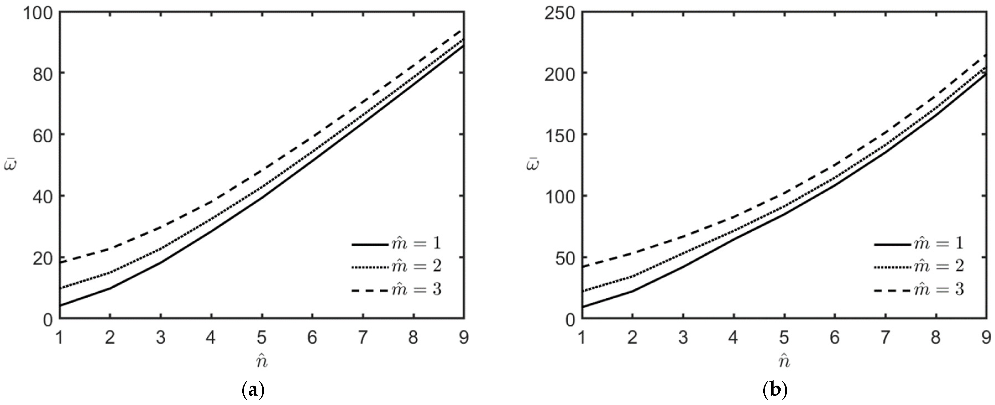
Figure 2a,b shows the variations in the microplate’s lowest frequency with different values of m ^ and n ^ for the cases of l/h = 0 and l/h = 0.5, respectively.
The relevant geometric parameters are as follows: L x = L y ,   L x / h = 10 , and h = 17.8 × 10 6   m . The inhomogeneity index is κ p = 3 . It is shown that the lowest frequency always occurs at m ^ ,   n ^ = ( 1 ,   1 ) , and the lowest frequency appears to increase monotonically when the values of m ^ and n ^ increase. The material length-scale parameter l makes the microplate stiffer, resulting in an increase in its lowest natural frequency.
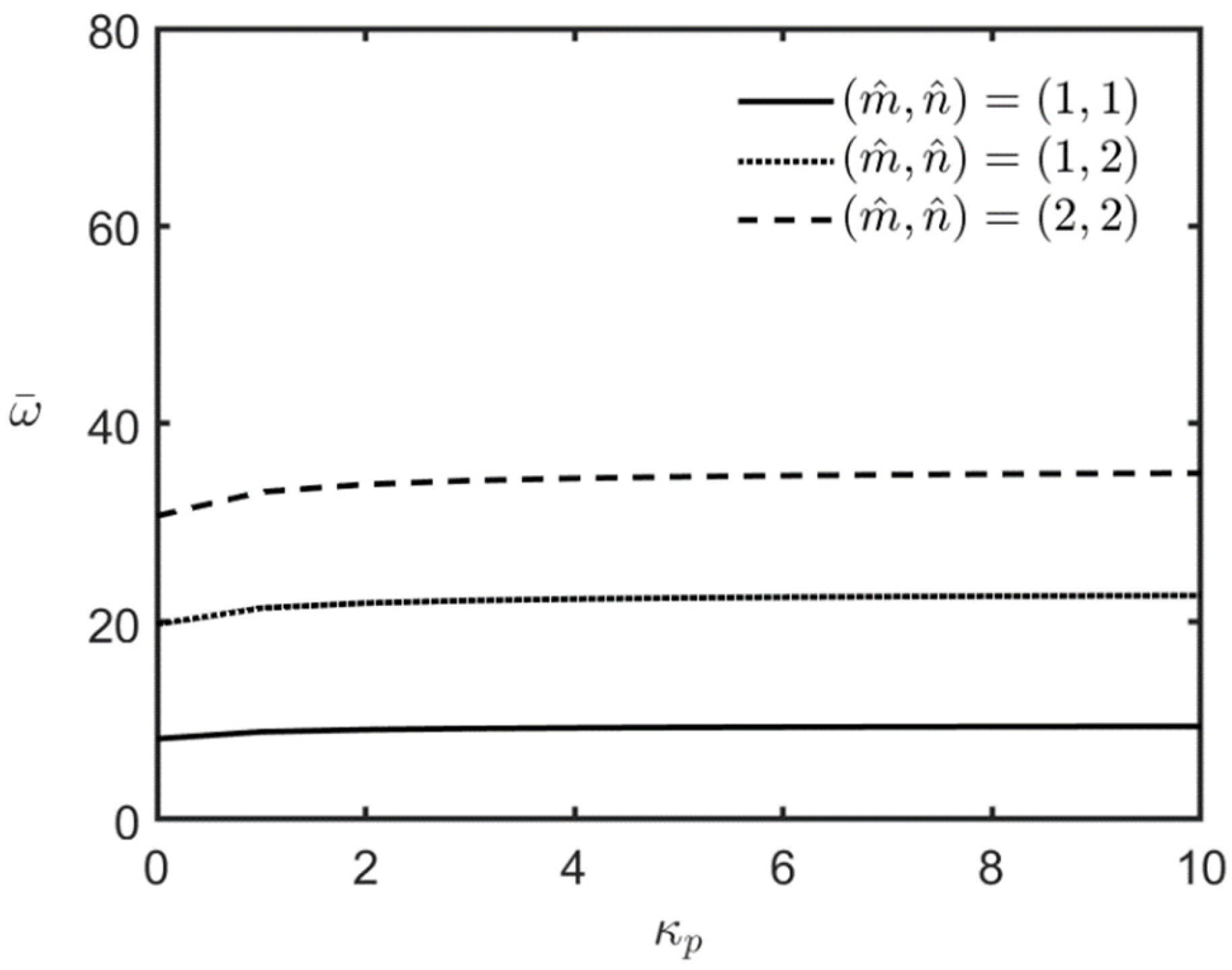
Figure 3 shows the variations in the microplate’s lowest frequency with the inhomogeneity index for the wave number pairs m ^ ,   n ^ = ( 1 ,   1 ) , (1, 2), and (2, 2). The relevant geometric parameters are as follows: L x = L y ,   L x / h = 10 , and h = 17.8 × 10 6 m . In addition, l/h = 0.5.
The results in Figure 3 reveal that the microplate’s lowest frequency exhibits only minor changes as the value of the inhomogeneity index increases. This is because the differences between the stiffness coefficients of the phase materials BaTiO3 and CoFe2O4 are minor. An increase in the inhomogeneity index leads to an increase in the volume fraction of the stiffer material CoFe2O4, resulting in a minor increase in the microplate’s overall stiffness, which in turn leads to a slight increase in its lowest frequency.
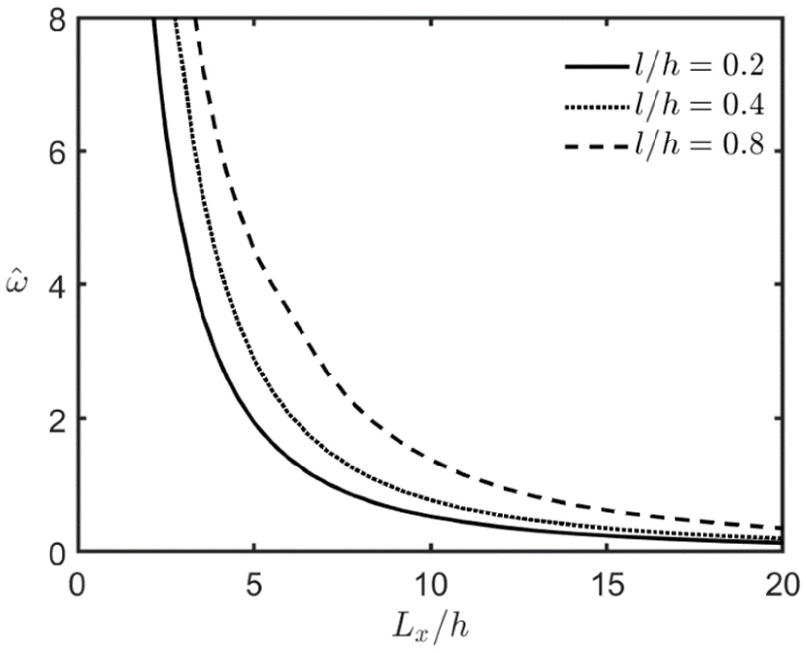
Figure 4 shows the variations in the square microplate’s lowest frequency with the Lx/h ratio. The relevant material parameters are as follows: κ p = 3 ,   l / h = 0.2 ,   0.4 ,   and   0.8 , and l = 8.8 × 10 6   m . The dimensionless frequency is replaced with the following form: ω ^ = 10 ω   h   ρ F / c 11 F . The microplate’s lowest frequency is shown to decrease when the value of the Lx/h ratio increases. This is because an increase in the Lx/h ratio represents the microplate of interest becoming thinner, resulting in a decrease in the microplate’s overall stiffness and, subsequently, a decrease in its lowest frequency.

4.2.2. Loaded FG-MEE Microplates Under Closed-Circuit Surface Conditions

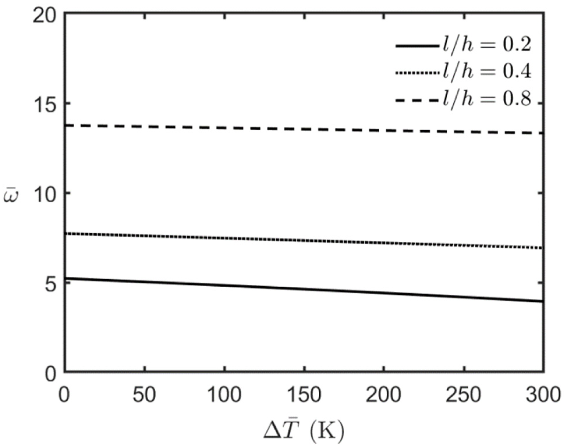
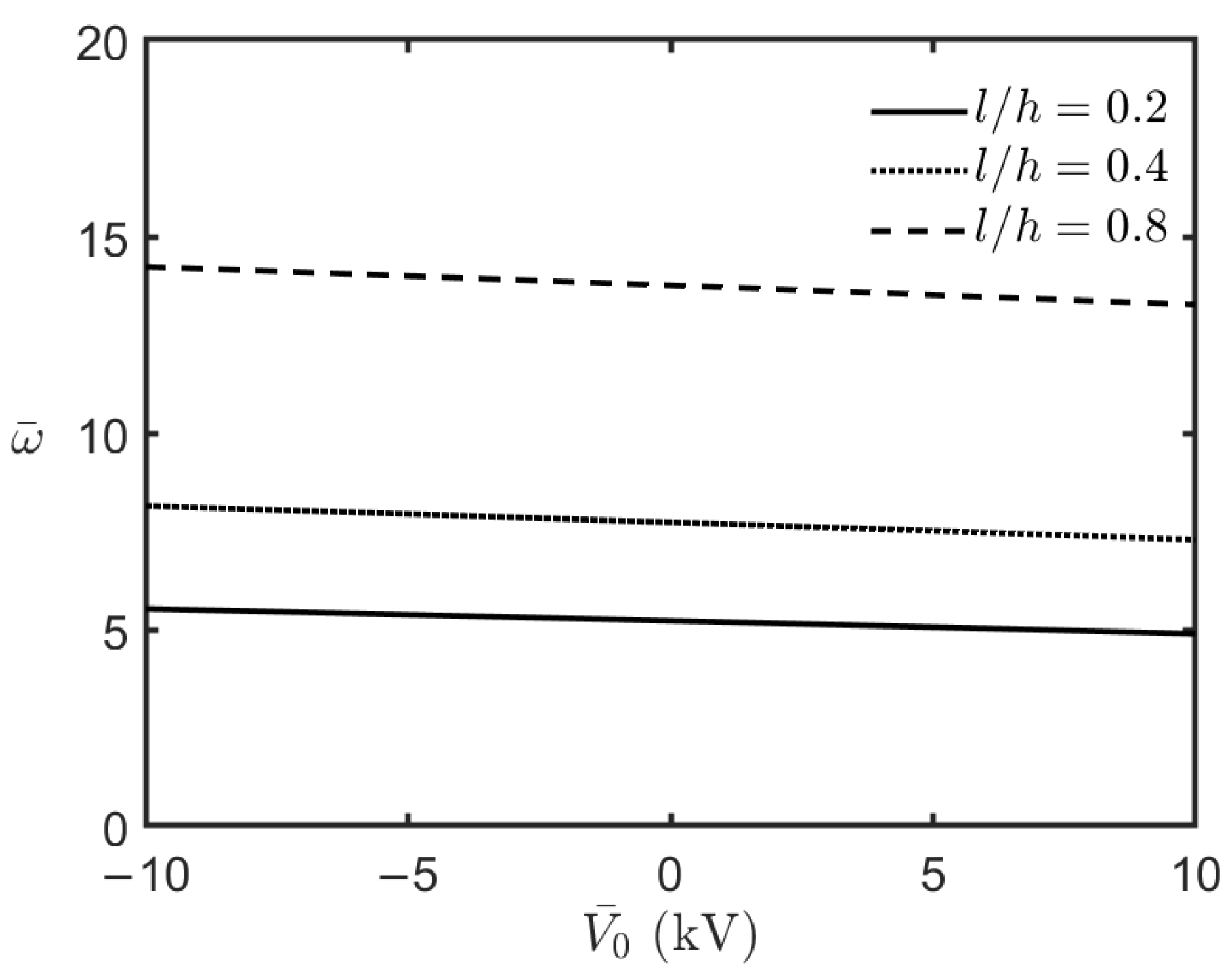
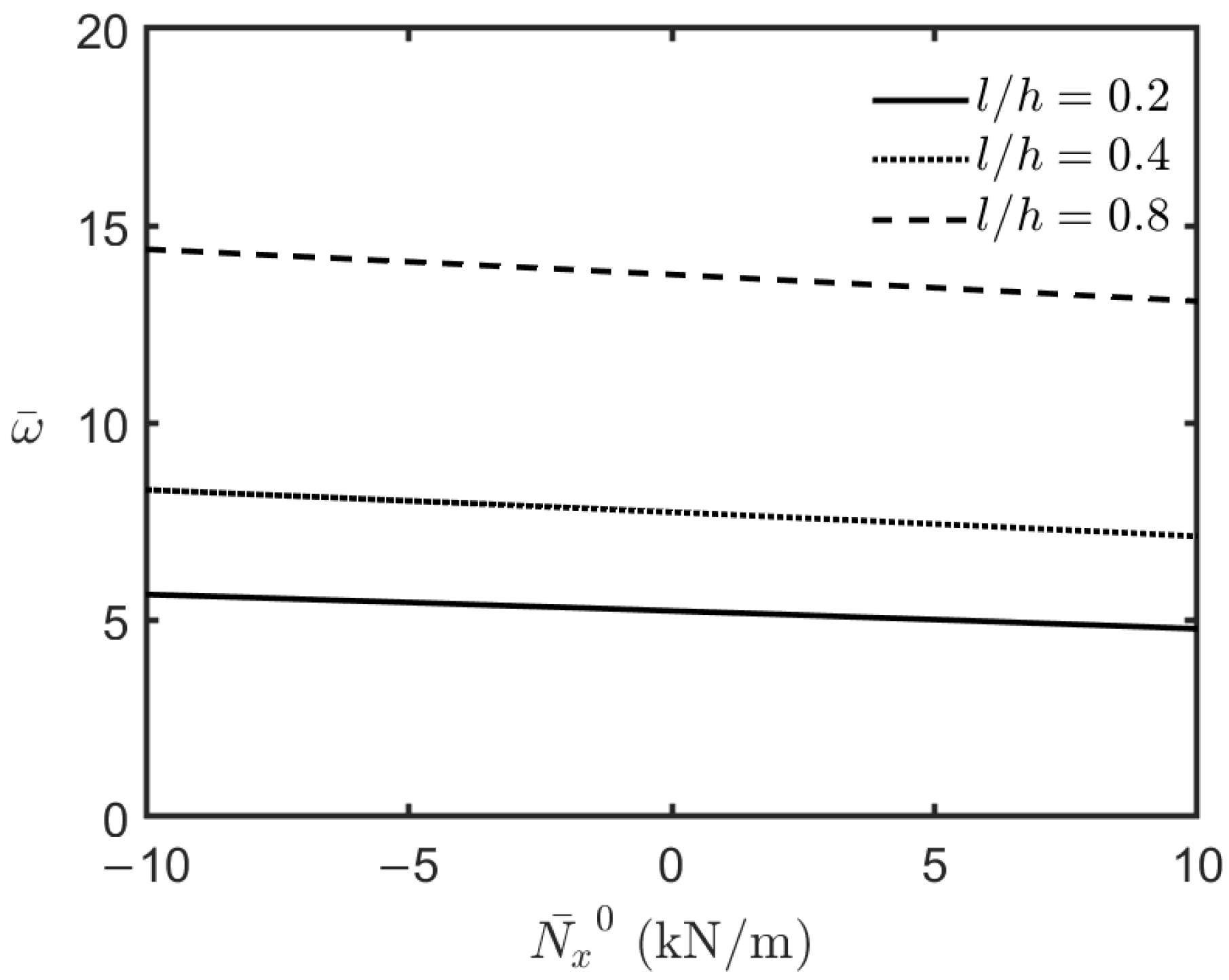
This section examines the free vibration characteristics of an FG-MEE microplate under fully simply supported conditions, closed-circuit surface conditions, and magneto-electro-thermal mechanical loads. Figure 5, Figure 6, Figure 7 and Figure 8 illustrate the variations in the FG-MEE microplate’s lowest frequency with respect to the magnitude of the applied uniform temperature changes, electric potential, magnetic potential, and biaxial compressive loads, respectively. The results in Figure 5, Figure 6 and Figure 8 show that the microplate’s lowest frequency decreases when the magnitude of the uniform temperature changes, electric potential, and biaxial compressive loads increase. This indicates that an increase in the magnitude of uniform temperature changes, electric potential, and biaxial compressive loads results in a set of initial compressive forces induced in the microplate, leading to a decrease in the microplate’s overall stiffness, and consequently, and in turn a decrease in the microplate’s lowest frequency. On the contrary, the results in Figure 7 show that the microplate’s lowest frequency increases when the magnitude of the applied magnetic potential increases due to a set of initial in-plane tension forces induced in the microplate.

5. Conclusions

In this work, we developed a unified SDSDT based on the CCST capable of investigating the free vibration characteristics of an FG-MEE microplate under fully simply supported conditions, open- or closed-circuit surface conditions, and magneto-electro-thermo-mechanical loads, where the couple stress and thickness stretching effects are considered. By employing Hamilton’s principle, we obtained the unified SDSDT’s strong form. By utilizing a specific shape function that characterizes the shear deformation distribution along the thickness in this formulation, various CCST-based SDSDTs could be reproduced, including the CCST-based CPT, first-order SDT, Reddy’s refined SDT, sinusoidal SDT, exponential SDT, and hyperbolic SDT. By employing the double Fourier series expansion method, we obtained the Navier-type analytical solutions for the natural frequency of an FG-MEE microplate. The formulation for analyzing an FG-MEE microplate could be simplified to that of an FG-MEE macroscale plate and an FG piezoelectric microplate by setting the material length-scale parameter to zero and the relevant magnetic coefficients to zero, respectively.
In the validation and comparison studies, the solutions of the CCST-based Reddy’s refined SDT, sinusoidal SDT, exponential SDT, and hyperbolic SDT were found to agree closely with one another. Their solutions were shown to be in excellent agreement with relevant 3D solutions reported in the literature. It was noted that the shear deformation effect and the thickness stretching effect made the microplate softer, leading to a decrease in its lowest frequency. The material length-scale parameter effect made the microplate stiffer, resulting in an increase in its lowest resonant frequency.
The parametric studies revealed that increasing the magnitude of the applied uniform temperature changes, electric potential, and biaxial compressive forces decreased the FG-MEE microplate’s lowest frequency. On the contrary, an increase in the magnitude of the applied magnetic potential increased the FG-MEE microplate’s lowest frequency.
The advantage of the consistent couple stress theory (CCST) over the traditional couple stress theory is that the number of material length-scale parameters required for analyzing an elastic body is reduced from two to one. Additionally, the strong and weak forms of the CCST have been demonstrated to be feasible for developing analytical and numerical methods, respectively. In contrast, the traditional couple stress theory has been shown to pose an indeterminate problem, hindering its application. Furthermore, the couple stress effect is significant when the structure’s dimensions are stretched approaching the microscale, i.e., 1 × 10 6 m . Other higher-order strain gradient effects become significant when the structure’s dimensions are stretched approaching the nanoscale, i.e., 1 × 10 9 m . Therefore, the application of CCST is appropriate for the structure’s dimensions between the micrometer and nanometer ranges.
Because the results of the free vibration characteristic of an FG-MEE microplate subjected to magneto-electro-thermo-mechanical loads are rare, the solutions presented in this study can provide a reference for their validation and comparison when a new relevant theory is proposed. In addition, the unified SDSDT could be extended to analyze the static bending, static buckling, and dynamic buckling behaviors of an FG-MEE microplate. Its weak formulation could also be employed to develop relevant numerical methods such as the finite element method and the meshless method.

Author Contributions

Conceptualization, C.-P.W.; methodology, C.-P.W.; software, C.-D.H.; validation, C.-P.W. and C.-D.H.; investigation: C.-P.W. and C.-D.H.; resources, C.-P.W.; data curation, C.-D.H.; writing—original draft preparation, C.-P.W.; writing—review and editing, C.-P.W.; visualization, C.-P.W.; supervision, C.-P.W.; project administration, C.-P.W.; funding acquisition, C.-P.W. All authors have read and agreed to the published version of the manuscript.

Funding

This research was funded by the National Science and Technology Council of Taiwan, under grant number NSTC 112-2221-E-006-048-MY2.

Data Availability Statement

The data presented in this work are available upon request from the corresponding author.

Conflicts of Interest

The authors declare that they have no conflicts of interest.

Abbreviations

The following abbreviations are used in this paper:
CCMClassical continuum mechanics
CCSTConsistent couple stress theory
CPTClassical plate theory
SDSDTSize-dependent shear deformation theory
SDTShear deformation theory
FGFunctionally graded
HOCMHigher-order continuum mechanics
MCSTModified couple stress theory
MEEMagneto-electro-elastic
2D Two-dimensional
3DThree-dimensional

Appendix A. The Generalized Force/Moment Resultants–Generalized Displacement Components Relationships

The generalized force/moment resultants–generalized displacement components relationships are expressed as follows:
N x x     σ = h / 2 h / 2 σ x x   d z = A   11   c   u , x + A   12   c   v , y B   11   c w , x x B   12   c w , y y + A   11 f   c   γ x , x + A   12 f   c   γ y , y + F 13 f c   γ z F ^ 31 f e   ϕ F ^ 31 f q   ψ + A 31   e 2 V ¯ 0 / h + A 31   q 2 C ¯ 0 / h A α 1   c Δ T ,
N y y     σ = h / 2 h / 2 σ y y   d z = A   12   c   u , x + A   22   c   v , y B   12   c w , x x B   22   c w , y y + A   12 f   c   γ x , x + A   22 f   c   γ y , y + F 23 f   c   γ z F ^ 32 f   e   ϕ F ^ 32 f   q   ψ + A   32   e 2 V ¯ 0 / h + A   32   q 2 C ¯ 0 / h A   α 2   c Δ T ,
N x y     σ = h / 2 h / 2 σ x y   d z = A   66   c   u , y + A   66   c   v , x 2 B   66   c w , x y + A   66 f   c   γ x , y +   γ y , x ,
M x x     σ = h / 2 h / 2 σ x x   z   d z = B   11   c   u , x + B   12   c   v , y D   11   c w , x x D   12   c w , y y + B   11 f   c   γ x , x + B   12 f   c   γ y , y + P 13 f   c     γ z P ^ 31 f   e   ϕ P ^ 31 f   q   ψ + B 31   e 2 V ¯ 0 / h + B 31   q 2 C ¯ 0 / h B α 1   c Δ T ,
M y y     σ = h / 2 h / 2 σ y y   z   d z = B   12   c   u , x + B   22   c   v , y D   12   c w , x x D   22   c w , y y + B   12 f   c   γ x , x + B   22 f   c   γ y , y + P 23 f   c   γ z P ^ 32 f   e   ϕ P ^ 32 f   q   ψ + B 32   e 2 V ¯ 0 / h + B 32   q 2 C ¯ 0 / h B α 2   c Δ T ,
M x y     σ = h / 2 h / 2 σ x y   z   d z = B   66   c   u , y + B   66   c   v , x 2 D   66   c w , x y + B   66 f   c γ x , y + γ y , x ,
Q x z     σ = h / 2 h / 2   σ x z   d z = E   55 f   c   γ x + E   55 f   c   γ z , x E ^ 15 f   e   ϕ , x E ^ 15 f   q   ψ , x ,
Q y z     σ = h / 2 h / 2   σ y z   d z = E   44 f   c   γ y + E   44 f   c   γ z , y E ^ 24 f   e   ϕ , y E ^ 24 f   q   ψ , y ,
P x x     σ = h / 2 h / 2 σ x x   f   d z = A   11 f   c   u , x + A   12 f   c   v , y B   11 f   c w , x x B   12 f   c w , y y + H   11 f   c   γ x , x + H   12 f   c   γ y , y + L 13 f   c   γ z   L ^ 31 f   e   ϕ L ^ 31 f   q   ψ + A 31 f   e 2 V ¯ 0 / h + A 31 f   q 2 C ¯ 0 / h A   α 1 f   c Δ T ,
P y y     σ = h / 2 h / 2 σ y y   f   d z = A   12 f   c   u , x + A   22 f   c   v , y B   12 f   c w , x x B   22 f   c w , y y + H   12 f   c   γ x , x + H   22 f   c   γ y , y + L 32 f   c   γ z L ^ 32 f   e   ϕ L ^ 32 f   q   ψ + A 32 f   e 2 V ¯ 0 / h + A 32 f   q 2 C ¯ 0 / h A α 2 f   c Δ T ,
P x y     σ = h / 2 h / 2 σ x y   f   d z = A   66 f   c   u , y + A   66 f   c   v , x 2 B   66 f   c w , x y + H   66 f   c   γ x , y +   γ y , x ,
R x z     σ = h / 2 h / 2   σ x z   D f   d z = J   55 f   c   γ x + J   55 f   c   γ z , x J ¯ 15 f   e   ϕ , x J ¯ 15 f   q   ψ , x ,
R y z     σ = h / 2 h / 2   σ y z   D f   d z = J 44 f   c   γ y + J 44 f   c   γ z , y J ¯ 24 f   e   ϕ , y J ¯ 24 f   q   ψ , y ,
S z z     σ = h / 2 h / 2 σ   z z   D 2 f   d z = F 13 f   c   u , x + F 23 f   c   v , y P 13 f   c w , x x P 23 f   c w , y y + L 13 f   c   γ x , x + L   23 f   c   γ y , y + N 33 f   c   γ z N ¯ 33 f   e   ϕ N ¯ 33 f   q   ψ + F 33 f   e 2 V ¯ 0 / h + F 33 f   q 2 C ¯ 0 / h F α 3 f   c Δ T ,
M x y     μ = h / 2 h / 2 μ x y   d z = A 33   b / 4 w , x x + w , y y + E 33 f   b / 8 γ x , x + γ y , y γ z , x x γ z , y y ,
M x z     μ = h / 2 h / 2 μ x z   d z = A 22   b / 8 u , x y v , x x A 22 f   b / 8 γ x , x y γ y , x x + F 22 f   b / 8 γ y γ z , y ,
M y z     μ = h / 2 h / 2 μ   y z   d z = A 11   b / 8 u , y y v , x y A 11 f   b / 8 γ x , y y γ y , x y F 11 f b / 8 γ x γ z , x ,
R x z     μ = h / 2 h / 2 μ x z   f   d z = A 22 f   b / 8 u , x y v , x x H 22 f   b / 8 γ x , x y γ y , x x + L 22 f   b / 8 γ y γ z , y ,
R y z     μ = h / 2 h / 2 μ y z   f   d z = A 11 f   b / 8 u , y y v , x y H 11 f   b / 8 γ x , y y γ y , x y L 11 f   b / 8 γ x γ z , x ,
S x y     μ = h / 2 h / 2 μ   x y   D f   d z = E 33 f   b / 4 w , x x + w , y y + J 33 f   b / 8 γ x , x + γ y , y γ z , x x γ z , y y ,
T x z     μ = h / 2 h / 2 μ x z   D 2 f   d z = F 22 f   b / 8 u , x y v , x x L 22 f   b / 8 γ x , x y γ y , x x + N 22 f   b / 8 γ y γ z , y ,
T y z     μ = h / 2 h / 2 μ   y z   D 2 f   d z = F 11 f   b / 8 u , y y v , x y L 11 f   b / 8 γ x , y y γ y , x y N 11 f   b / 8 γ x γ z , x ,
R   x D = h / 2 h / 2 D x   g   d z = J ¯ 15 f   e   γ x + γ z , x + J ^ 11 f   η   ϕ , x + J ^ 11 f   d   ψ , x ,
R   x B = h / 2 h / 2 B x   g   d z   = J ¯ 15 f   q   γ x + γ z , x + J ^ 11 f   d   ϕ , x + J ^ 11 f   β   ψ , x ,
R   y D = h / 2 h / 2 D y   g   d z = J ¯ 24 f   e   γ y + γ z , y + J ^ 22 f   η   ϕ , y + J ^ 22 f   d   ψ , y ,
R   y B = h / 2 h / 2 B y   g   d z = J ¯ 24 f   q   γ y + γ z , y + J ^ 22 f   d   ϕ , y + J ^ 22 f   β   ψ , y ,
T   z D = h / 2 h / 2 D z   D g   d z = F ^ 31 f   e   u , x + F ^ 32 f   e   v , y P ^ 31 f   e w , x x P ^ 32 f   e w , y y + L ^ 31 f   e   γ x , x + L ^ 32 f   e   γ y , y + N ^ 33 f   e γ z + N ^ 33 f   η   ϕ + N ^ 33 f   d   ψ F ^ 33 f   η 2 V ¯ 0 / h F ^ 33 f   d 2 C ¯ 0 / h F ^ α 3 f   e Δ T ,
T   z B = h / 2 h / 2 B z   D g   d z = F ^ 31 f   q   u , x + F ^ 32 f   q   v , y P ^ 31 f   q w , x x P ^ 32 f   q w , y y + L ^ 31 f   q   γ x , x + L ^ 32 f   q   γ y , y + N ¯ 33 f   q γ z + N ^ 33 f   d   ϕ + N ^ 33 f   β   ψ F ^ 33 f   d 2 V ¯ 0 / h F ^ 33 f   β 2 C ¯ 0 / h F ^ α 3 f   q Δ T ,
where
A   k j   l B k j   l D k j   l A k j f   l B k j f   l D k j f   l E k j f   l F k j f   l H k j f   l J k j f   l P k j f   l L k j f   l M k j f   l N k j f   l = h / 2 h / 2   l k j     1 z z 2 f z f z 2 f D f D 2 f f 2 D f 2 f D f z D 2 f D f D 2 f D 2 f 2   d z ,
E ^ k j f   l F ^ k j f   l J ^ k j f   l J ¯ k j f   l K ^ k j f   l L ^ k j f   l M ^ k j f   l M ¯ k j f   l N ^ k j f   l N ¯ k j f   l P ^ k j f   l = h / 2 h / 2   l k j     g D g g 2 g D f g f D g f g D 2 f D g D f D g 2 D 2 f D g D g z   d z ,
in which the subscript k = 1, 2, and 3. The variables l k j will be changed to a k k ,   b k k ,   and   c α k when l = b and c, respectively. The variables lij will be changed to e k j when l = e, where k = 1–3, and l = 1–6. D g = d g ( z ) / d z = ( π / h )   sin π z / h ; and
A α k   l B α k   l D α k   l = h / 2 h / 2 l α k 1 z z 2   d z l = c ,   e ,   and   q ,
A α k f   l B α k f   l D α k f   l E α k f   l F α k f   l F ^ α k f   l = h / 2 h / 2 l α k f 1 z z 2 D f D 2 f D g   d z l = c ,   e ,   and   q ,

Appendix B. The Detailed Expressions of Generalized Initial In-Plane Force Resultants

The detailed expressions of the resultant forces and bending moments N ¯ x i , N ¯ y i , R ¯ x i , R ¯ y i , T ¯ x i , and T ¯ y i   i = e ,   q ,   t ,   and   0 are given as follows:
N ¯ x e =   h / 2 h / 2   e 31 2 V ¯ 0 / h   d z = A   31   e 2 V ¯ 0 / h ,
N ¯ y   e =   h / 2 h / 2   e 32 2 V ¯ 0 / h   d z = A   32   e 2 V ¯ 0 / h ,
R ¯ x e =   h / 2 h / 2   e 31 2 V ¯ 0 / h   D f   d z = E   31 f   e 2 V ¯ 0 / h ,
R ¯ y   e =   h / 2 h / 2   e 32 2 V ¯ 0 / h   D f   d z = E   32 f   e 2 V ¯ 0 / h ,
T ¯   x e =   h / 2 h / 2   e 31 2 V ¯ 0 / h   D f 2   d z = J   31 f   e 2 V ¯ 0 / h ,
T ¯ y   e =   h / 2 h / 2   e 32 2 V ¯ 0 / h   D f 2   d z = J   32 f   e 2 V ¯ 0 / h ;
N ¯ x q =   h / 2 h / 2   q 31 2 C ¯ 0 / h   d z = A   31   q 2 C ¯ 0 / h ,
N ¯ y   q =   h / 2 h / 2   q 32 2 C ¯ 0 / h   d z = A   32   e 2 C ¯ 0 / h ,
R ¯ x q =   h / 2 h / 2   q 31 2 C ¯ 0 / h   D f   d z = E   31 f   q 2 C ¯ 0 / h ,
R ¯ y   q =   h / 2 h / 2   q 32 2 C ¯ 0 / h   D f   d z = E   32 f   q 2 C ¯ 0 / h ,
T ¯   x q =   h / 2 h / 2   q 31 2 C ¯ 0 / h   D f 2   d z = J   31 f   q 2 C ¯ 0 / h ,
T ¯ y   q =   h / 2 h / 2   q 32 2 C ¯ 0 / h   D f 2   d z = J   32 f   q 2 C ¯ 0 / h ;
N ¯ x t =   h / 2 h / 2   c α 1 Δ T ¯   d z = Δ T ¯   A   α 1   c ,
N ¯ y   t =   h / 2 h / 2   c α 2 Δ T ¯   d z = Δ T ¯ A   α 2   c ,
R ¯ x   t =   h / 2 h / 2   c α 1 Δ T ¯   D f   d z = Δ T ¯ E   α 1 f   c ,
R ¯ y   t =   h / 2 h / 2   c α 2 Δ T ¯   D f   d z = Δ T ¯ E   α 2 f   c ,
T ¯   x e =   h / 2 h / 2   c α 1 Δ T ¯   D f 2   d z = Δ T ¯ J   α 1 f   c ,
T ¯ y   t =   h / 2 h / 2   c α 2 Δ T ¯   D f 2   d z = Δ T ¯ J   α 2 f   c ;
N ¯ x 0 =   h / 2 h / 2   σ ¯ x x 0   d z =   σ ¯ x x 0   h ,
N ¯ y   0 =   h / 2 h / 2   σ ¯ y y 0   d z =   h / 2 h / 2 c p   σ ¯ x x 0   d z = λ p σ ¯ x x 0   h ,
R ¯ x   0 =   h / 2 h / 2   σ ¯ x x   0   D f   d z =   σ ¯ x x   0   E D f   1 ,
R ¯ y   0 =   h / 2 h / 2   σ ¯ y y   0   D f   d z =   σ ¯ y y   0   E D f   1 = λ p σ ¯ x x 0   E D f   1 ,
T ¯ x 0 =   h / 2 h / 2   σ ¯ x x 0   D f 2   d z = σ ¯ x x 0 E D f   2 ,
T ¯ y 0 =   h / 2 h / 2   σ ¯ y y 0   D f 2   d z = λ p σ ¯ x x 0 E D f   2 ,
where λ p denotes the magnitude ratio between the applied loads in the x and y directions, which is expressed as λ p = σ ¯ y y   0 / σ ¯ x x   0 ; E D f   1 = h / 2 h / 2 D f   d z , and E D f   2 = h / 2 h / 2 D f 2   d z .

Appendix C. The Detailed Expressions of Kij and Ik

The detailed expressions of Kij and Ik are given as follows:
K 11 = A   11   c x x + A   66   c y y + 1 / 16 A 22   b x x y y + A 11   b y y y y ,
K 12 = A   12   c + A   66   c x y 1 / 16 A   22   b x x x y + A   11   b x y y y ,
K 13 = B   11   c x x x + B   12   c + 2 B   66   c x y y ,
K 14 = A   11 f   c   x x + A   66 f   c   y y + 1 / 16 A 22 f   b x x y y + A 11 f   b y y y y + F 11 f   b y y ,
K 15 = A   12 f   c   + A   66 f   c x y 1 / 16 A 22 f   b x x x y + A 11 f   b x y y y + F 22 f   b x y ,
K 16 = F   13 f   c x 1 / 16 F   11 f   b F   22 f   b   x y y ,
K 17 = F ^ 31 f   e x ,
K 18 = F ^ 31 f   q x ,
K 21 = K 12 ,
K 22 = A   66   c x x + A   22   c y y + 1 / 16 A   22   b x x x x + A   11   b x x y y ,
K 23 = B   12   c + 2 B   66   c x x y + B   22   c   y y y ,
K 24 = A   12 f   c   + A   66 f   c x y 1 / 16 A 22 f   b x x x y + A 11 f   b x y y y + F 11 f   b x y ,
K 25 = A   66 f   c   x x + A   22 f   c y y + 1 / 16 A 22 f   b x x x x + A 11 f   b x x y y + F 22 f   b x x ,
K 26 = F   23 f   c y + 1 / 16 F   11 f   b F   22 f   b   x x y ,
K 27 = F ^ 32 f   e y ,
K 28 = F ^ 32 f   q y ,
K 31 = K 13 ,
K 32 = K 23 ,
K 33 = D   11   c x x x x + 2 D   12   c + 4 D   66   c x x y y + D   22   c y y y y + A 33 b / 4 x x x x + 2 x x y y + y y y y ,
K 34 = B   11 f   c   x x x + B   12 f   c + 2 B   66 f   c x y y E 33 f b / 8 x x x + x y y ,
K 35 = B   12 f   c + 2 B   66 f   c x x y + B   22 f   c   y y y E 33 f   b / 8 x x y + y y y ,
K 36 = P   13 f   c x x + P   23 f   c y y +   E   33 f   b / 8 x x x x + 2 x x y y + y y y y ,
K 37 = P ^ 31 f   e x x + P ^ 32 f   e y y ,
K 38 = P ^ 31 f   q x x + P ^ 32 f   q y y ,
K 41 = K 14 ,
K 42 = K 24 ,
K 43 = K 34 ,
K 44 = H   11 f   c   x x + H   66 f   c   y y J   55 f   c + 1 / 16 H 22 f   b x x y y + H 11 f   b y y y y J 33 f   b x x + 2 L 11 f   b y y + N 11 f   b ,
K 45 = H   12 f   c   + H   66 f   c x y 1 / 16 H 22 f   b x x x y + H 11 f   b x y y y + J 33 f   b + L 11 f   b + L 22 f   b x y ,
K 46 = J   55 f   c   L   13 f   c x + 1 / 16 J 33 f   b x x x + J 33 f   b L 11 f   b + L 22 f   b x y y N 11 f   b x ,
K 47 = L ^ 31 f   e J ¯ 15 f   e x ,
K 48 = L ^ 31 f   q J ¯ 15 f   q x ,
K 51 = K 15 ,
K 52 = K 25 ,
K 53 = K 35 ,
K 54 = K 45 ,
K 55 = H 66 f   c   x x + H 22 f   c   y y J 44 f   c + 1 / 16 H 22 f   b x x x x + H 11 f   b x x y y + 2 L 22 f   b x x J 33 f   b y y + N 22 f   b ,
K 56 = J   44 f   c   L   23 f   c y + 1 / 16 J 33 f   b y y y + J 33 f   b + L 11 f   b L 22 f   b x x y N 22 f   b y ,
K 57 = L ^ 32 f   e J ¯ 24 f   e y   ,
K 58 = L ^ 32 f   q J ¯ 24 f   q y   ,
K 61 = K 16 ,
K 62 = K 26 ,
K 63 = K 36 ,
K 64 = K 46 ,
K 65 = K 56 ,
K 66 = J 55 f   c   x x + J 44 f   c   y y N 33 f   c + 1 / 16 J 33 f   b x x x x + 2 J 33 f   b x x y y + J 33 f   b y y y y N 11 f   b x x N 22 f   b y y ,
K 67 = J ¯ 15 f   e x x +   J ¯ 24 f   e y y N ¯ 33 f   e ,
K 68 = J ¯ 15 f   q x x +   J ¯ 24 f   q y y N ¯ 33 f   q ,
K 71 = K 17 ,
K 72 = K 27 ,
K 73 = K 37 ,
K 74 = K 47 ,
K 75 = K 57 ,
K 76 = K 67 ,
K 77 = J ^ 11 f   η x x +   J ^ 22 f   η y y N ^ 33 f   η ,
K 78 = J ^ 11 f   d x x +   J ^ 22 f   d y y N ^ 33 f   d ,
K 81 = K 18 ,
K 82 = K 28 ,
K 83 = K 38 ,
K 84 = K 48 ,
K 85 = K 58   ,
K 86 = K 68 ,
K 87 = K 78 ,
K 88 = J ^ 11 f   β x x +   J ^ 22 f   β y y N ^ 33 f   β ;
I 0 I 1 I 2 I 3 I 4 I 5 I 6 I 7 = h / 2 h / 2 ρ   1 z z 2 f z f f 2 D f D f 2   d z .
where the definitions of the relevant coefficients are expressed in Equations (A29) and (A30).

Appendix D. The Detailed Expressions of kij, mij, and g i j k k = c , e , q , and t

The detailed expressions of kij, mij, and g i j k k = c ,   e ,   q ,   and   t are given as follows:
k 11 = m ˜ 2 A   11   c + n ˜ 2 A   66   c + 1 / 16 m ˜ 2 n ˜ 2 A 22   b + n ˜ 4 A 11   b ,
k 12 = k 21 = m ˜   n ˜ A   12   c + A   66   c 1 / 16 m ˜ 3   n ˜   A 22   b + m ˜   n ˜ 3 A 11   b ,
k 13 = k 31 = m ˜ 3 B   11   c m ˜   n ˜ 2 B   12   c + 2 B   66   c ,
k 14 = k 41 = m ˜ 2 A   11 f     c + n ˜ 2 A   66 f     c + 1 / 16 m ˜ 2 n ˜ 2 A 22 f   b +   n ˜ 4 A 11 f   b n ˜ 2   F 11 f   b ,
k 15 = k 51 = m ˜   n ˜ A   12 f     c + A   66 f     c 1 / 16 m ˜ 3   n ˜   A 22 f   b + m ˜   n ˜ 3 A 11 f   b m ˜   n ˜   F 22 f   b ,
k 16 = k 61 = m ˜   F 13 f   c + 1 / 16 m ˜   n ˜ 2 F 11 f   b F 22 f   b ,
k 17 = k 71 = m ˜   F ^ 31 f   e ,
k 22 = m ˜ 2 A   66   c + n ˜ 2 A   22   c + 1 / 16 m ˜ 4 A 22   b + m ˜ 2 n ˜ 2   A 11   b ,
k 23 = k 32 = m ˜ 2   n ˜ B   12   c + 2 B   66   c n ˜ 3 B   22   c ,
k 24 = k 42 = m ˜   n ˜ A   12 f   c + A   66 f   c 1 / 16 m ˜ 3 n ˜   A   22 f   b + m ˜   n ˜ 3 A   11 f   b m ˜   n ˜   F 11 f   b ,
k 25 = k 52 = m ˜ 2 A   66 f   c + n ˜ 2 A   22 f   c + 1 / 16 m ˜ 4 A   22 f   b + m ˜ 2 n ˜ 2 A   11 f   b m ˜ 2 F   22 f   b ,
k 26 = k 62 = n ˜   F 23 f   c 1 / 16 m ˜ 2   n ˜ F 11 f   b F   22 f   b ,
k 27 = k 72 = n ˜   F ^ 32 f   e ,
k 28 = k 82 = n ˜   F ^ 32 f   q ,
k 33 = m ˜ 4 D   11   c + m ˜ 2 n ˜ 2 2 D   12   c + 4 D   66   c + n ˜ 4 D   22   c + 1 / 4 m ˜ 4 + 2 m ˜ 2 n ˜ 2 + n ˜ 4 A   33   b ,
k 34 = k 43 = m ˜ 3 B   11 f   c m ˜   n ˜ 2 B   12 f   c + 2 B   66 f   c 1 / 8 m ˜ 3 + m ˜ n ˜ 2 E 33 f   b ,
k 35 = k 53 = m ˜ 2   n ˜ B   12 f   c + 2 B   66 f   c n ˜ 3 B   22 f   c 1 / 8 m ˜ 2   n ˜ + n ˜ 3 E 33 f   b ,
k 36 = k 63 = m ˜ 2 P 13 f   c + n ˜ 2 P 32 f   c + 1 / 8 m ˜ 4 + 2   m ˜ 2 n ˜ 2 + n ˜ 4 E 33 f   b ,
k 37 = k 73 = m ˜ 2 P ^ 31 f   e n ˜ 2 P ^ 32 f   e ,
k 38 = k 83 = m ˜ 2 P ^ 31 f   q n ˜ 2 P ^ 32 f   q ,
k 44 = m ˜ 2 H   11 f   c + n ˜ 2 H   66 f   c + J   55 f   c + 1 / 16 m ˜ 2 n ˜ 2   H 22 f   b + n ˜ 4 H 11 f   b + m ˜ 2   J 33 f   b 2 n ˜ 2 L 11 f   b + N 11 f   b ,
k 45 = k 54 = m ˜   n ˜ H   12 f   c + H   66 f   c 1 / 16 m ˜ 3 n ˜   H 22 f   b + m ˜   n ˜ 3 H 11 f   b m ˜   n ˜ J 33 f   b + L 11 f   b + L 22 f   b ,
k 46 = k 64 = m ˜ J 55 f   c L 13 f   c 1 / 16 m ˜ 3 J 33 f   b + m ˜   n ˜ 2 J 33 f   b L 11 f   b + L 22 f   b + m ˜   N 11 f   b ,
k 47 = k 74 = m ˜ L ^ 31 f   e J ¯ 15 f   e ,
k 48 = k 84 = m ˜ L ^ 31 f   q J ¯ 15 f   q ,
k 55 = m ˜ 2 H   66 f   c + n ˜ 2 H   22 f   c + J   44 f   c + 1 / 16 m ˜ 4 H 22 f   b + m ˜ 2 n ˜ 2 H 11 f   b 2 m ˜ 2 L 22 f   b + n ˜ 2 J 33 f   b + N 22 f   b ,
k 56 = k 65 = n ˜ J 44 f   c L 23 f     c 1 / 16   n ˜ 3 J 33 f   b + m ˜ 2 n ˜ J 33 f   b + L 11 f     b L 22 f     b + n ˜   N 22 f   b ,
k 57 = k 75 = n ˜ J ¯ 24 f   e L ^ 32 f   e ,
k 58 = k 85 = n ˜ J ¯ 24 f   q L ^ 32 f     q ,
k 66 = m ˜ 2 J 55 f   c + n ˜ 2 J 44 f   c + N 33 f   c + 1 / 16 m ˜ 4 + 2 m ˜ 2 n ˜ 2 + n ˜ 4   J 33 f   b + m ˜ 2   N 11 f   b + n ˜ 2   N 22 f   b ,
k 67 = k 76 = m ˜ 2   J ¯ 15 f   e n ˜ 2   J ¯ 24 f   e N ¯   33 f   e ,
k 68 = k 86 = m ˜ 2   J ¯ 15 f   q n ˜ 2   J ¯ 24 f   q N ¯   33 f   q ,
k 77 = m ˜ 2   J ^ 11 f   η n ˜ 2   J ^ 22 f   η N ^   33 f   η ,
k 78 = k 87 = m ˜ 2   J ^ 11 f   d n ˜ 2   J ^ 22 f   d N ^   33 f   d ,
k 88 = m ˜ 2   J ^ 11 f   β n ˜ 2   J ^ 22 f   β N ^   33 f   β ;
m 11 = m 22 = I 0 ,
m 13 = m 31 = m ˜   I 1 ,
m 14 = m 41 = m 25 = m 52 = I 3 ,
m 23 = m 32 = n ˜   I 1 ,
m 25 = m 52 =   I 3 ,
m 33 = I 0 + m ˜ 2 + n ˜ 2   I 2 ,
m 34 = m 43 = m ˜   I 4 ,
m 35 = m 53 = n ˜   I 4 ,
m 36 = m 63 =   I 6 ,
m 44 =   m 55 = I 5 ,
m 66 =   I 7 ;
g 33 c =   m ˜ 2 + n ˜ 2   λ p 1 ,
g 36 c =   g 63 c = m ˜ 2   + n ˜ 2   λ p   λ 1 ,
g 66 c =   m ˜ 2 + n ˜ 2   λ p   λ 2 ,
λ 1 = 1 / h h / 2 h / 2 D f   d z ,
λ 2 = 1 / h   h / 2 h / 2 D f 2 d z ;
g 33 e = 2   m ˜ 2 A   31   e + n ˜ 2 A   32   e / h ,
g 36 e = g 63 e = 2   m ˜ 2 E   31 f   e + n ˜ 2 E   32 f   e / h ,
g 66 e = 2   m ˜ 2 J   31 f   e + n ˜ 2 J   32 f   e / h ;
g 33 q = 2   m ˜ 2 A   31   q + n ˜ 2 A   32   q / h ,
g 36   q = g 63   q = 2   m ˜ 2 E   31 f   q + n ˜ 2 E   32 f   q / h ,
g 66   q = 2   m ˜ 2 J   31 f   q + n ˜ 2 J   32 f   q / h ;
g 33   t =   m ˜ 2 A   α 1   c + n ˜ 2 A   α 2   c ,
g 36   t = g 63   t = m ˜ 2 E   α 1 f     c + n ˜ 2 E   α 2 f     c ,
g 66 e = m ˜ 2 J   α 1 f     c + n ˜ 2 J   α 2 f     c .

References

  1. Koizumi, M. FGM activities in Japan. Compos. Part B Eng. 1997, 28, 1–4. [Google Scholar] [CrossRef]
  2. Koizumi, A. Recent progress of functionally graded materials in Japan. Cream. Eng. Sci. Proc. 1992, 13, 333–347. [Google Scholar]
  3. Ding, S.; Wu, C.P. Optimization of material composition to minimize the thermal stresses induced in FGM plates with temperature-dependent material properties. Int. J. Mech. Mater. Des. 2018, 14, 527–549. [Google Scholar] [CrossRef]
  4. Wu, C.P.; Li, K.W. Multi-objective optimization of functionally graded beams using a genetic algorithm with non-dominated sorting. J. Compos. Sci. 2021, 5, 92. [Google Scholar] [CrossRef]
  5. Bargatin, I.; Kozinsky, I.; Roukes, M. Efficient electrothermal actuation of multiple modes of high-frequency nanoelectromechanical resonators. Appl. Phys. Lett. 2007, 9, 093116. [Google Scholar] [CrossRef]
  6. Jalili, N.; Laxminarayana, K. A review of atomic force microscopy imaging systems: Application to molecular metrology and biological sciences. Mechatronics 2004, 14, 907–945. [Google Scholar] [CrossRef]
  7. Muller, E.; Drasar, C.; Schilz, J.; Kaysser, W.A. Functionally graded materials for sensors and energy applications. Mater. Sci. Eng. A 2003, 362, 17–39. [Google Scholar] [CrossRef]
  8. Kumar, S.; Murthy Reddy, K.V.V.S.; Kumar, A.; Rohini Devi, G. Development and characterization of polymer-ceramic continuous fiber reinforced functionally graded composites for aerospace application. Aerosp. Sci. Technol. 2013, 26, 185–191. [Google Scholar] [CrossRef]
  9. Thai, H.T.; Vo, T.P.; Nguyen, T.K.; Kim, S.E. A review of continuum mechanics models for size-dependent analysis of beams and plates. Compos. Struct. 2017, 177, 196–219. [Google Scholar] [CrossRef]
  10. Eltaher, M.A.; Khater, M.E.; Emam, S.A. A review on nonlocal elastic models for bending, buckling, vibrations, and wave propagation of nanoscale beams. Appl. Math. Modell. 2016, 40, 4109–4128. [Google Scholar] [CrossRef]
  11. Shariati, M.; Shishesaz, M.; Sahbafar, H.; Pourabdy, M.; Hosseini, M. A review on stress-driven nonlocal elasticity theory. J. Comput. Appl. Mech. 2021, 52, 535–552. [Google Scholar]
  12. Wu, C.P.; Yu, J.J. A review of mechanical analyses of rectangular nanobeams and single-, double-, and multi-walled carbon nanotubes using Eringen’s nonlocal elasticity theory. Arch. Appl. Mech. 2019, 89, 1761–1792. [Google Scholar] [CrossRef]
  13. Wu, C.P.; Hu, H.X. A review of dynamic analyses of single- and multi-layered graphene sheets/nanoplates using various nonlocal continuum mechanics-based plate theories. Acta Mech. 2021, 232, 4497–4531. [Google Scholar] [CrossRef]
  14. Kong, S. A review on the size-dependent models of micro-beam and micro-plate based on the modified couple stress theory. Arch. Comput. Methods Eng. 2022, 29, 1–31. [Google Scholar] [CrossRef]
  15. Nguyen, H.X.; Nguyen, T.N.; Abdel-Wahab, M.; Bordas, S.P.A.; Nguyen-Xuan, H.; Vo, T.P. A refined quasi-3D isogeometric analysis for functionally graded microplates based on the modified couple stress theory. Comput. Methods Appl. Mech. Eng. 2017, 313, 904–940. [Google Scholar] [CrossRef]
  16. Hadjesfandiari, A.R.; Dargush, G.F. Couple stress theory for solids. Int. J. Solids Struct. 2011, 48, 2496–2510. [Google Scholar] [CrossRef]
  17. Hadjesfandiari, A.R. Size-dependent piezoelectricity. Int. J. Solids Struct. 2013, 50, 2781–2791. [Google Scholar] [CrossRef]
  18. Wu, C.P.; Hu, H.X. A unified size-dependent plate theory for static bending and free vibration analyses of micro- and nano-scale plates based on the consistent couple stress theory. Mech. Mater. 2021, 162, 104085. [Google Scholar] [CrossRef]
  19. Wu, C.P.; Lin, E.L. Free vibration analysis of porous functionally graded piezoelectric microplates resting on an elastic medium subjected to electric voltages. Arch. Mech. 2022, 74, 463–511. [Google Scholar]
  20. Thai, S.; Thai, H.T.; Vo, T.P.; Patel, V.I. Size-dependent behavior of functionally graded microplates based on the modified strain gradient elasticity theory and isogeometric analysis. Comput. Struct. 2017, 190, 219–241. [Google Scholar] [CrossRef]
  21. Thai, C.H.; Hung, P.T.; Nguyen-Xuan, H.; Phung-Van, P. A size-dependent mesh-free approach for magneto-electro-elastic functionally graded nanoplates based on nonlocal strain gradient theory. Eng. Struct. 2023, 292, 116521. [Google Scholar] [CrossRef]
  22. Le, T.M.; Vo, D.; Rungamornrat, J.; Bui, T.Q. Strain-gradient theory for shear deformation free-form microshells: Governing equations of motion and general boundary conditions. Int. J. Solids Struct. 2022, 248, 111579. [Google Scholar] [CrossRef]
  23. Carrera, E.; Zozulya, V.V. Carrera unified formulation (CUF) for the micropolar plates and shells. I. Higher Order theory. Mech. Adv. Mater. Struct. 2022, 29, 773–795. [Google Scholar] [CrossRef]
  24. Carrera, E.; Zozulya, V.V. Carrera unified formulation (CUF) for the micropolar plates and shells. II. Complete Linear expansion case. Mech. Adv. Mater. Struct. 2022, 29, 796–815. [Google Scholar] [CrossRef]
  25. Zozulya, V.V. Higher order theory of micropolar plates and shells. ZAMM J. Appl. Math. Mech. 2018, 98, 886–918. [Google Scholar] [CrossRef]
  26. Hassanpour, S.; Heppler, G.R. Micropolar elasticity theory: A survey of linear isotropic equations, representative notations, and experimental investigations. Math. Mech. Solids 2015, 22, 224–242. [Google Scholar] [CrossRef]
  27. Gul, U.; Aydogdu, M. Structural modelling of nanorods and nanobeams using doublet mechanics theory. Int. J. Mech. Mater. Des. 2018, 14, 195–212. [Google Scholar] [CrossRef]
  28. Karamanli, A. Structural behaviours of zigzag and armchair nanobeams using finite element doublet mechanics. Eur. J. Mech. A/Solids 2021, 89, 104287. [Google Scholar] [CrossRef]
  29. Trinh, L.C.; Nguyen, H.X.; Vo, T.P.; Nguyen, T.K. Size-dependent behaviour of functionally graded microbeams using various shear deformation theories based on the modified couple stress theory. Compos. Struct. 2016, 154, 556–572. [Google Scholar] [CrossRef]
  30. Liu, H.; Zhang, Q. Nonlinear dynamics of two-directional functionally graded microbeam with geometrical imperfection using unified shear deformable beam theory. Appl. Math. Model. 2021, 98, 783–800. [Google Scholar] [CrossRef]
  31. Simsek, M.; Reddy, J.N. A unified higher order beam theory for buckling of a functionally graded microbeam embedded in elastic medium using modified couple stress theory. Compos. Struct. 2013, 101, 47–58. [Google Scholar] [CrossRef]
  32. Li, Z.; Wang, H.; Zheng, S. Bending and free vibration of functionally graded piezoelectric microbeams based on the modified couple stress theory. Ann. Solid Struct. Mech. 2018, 10, 1–16. [Google Scholar] [CrossRef]
  33. Lou, J.; He, L.; Du, J. A unified higher order plate theory for functionally graded microplates based on the modified couple stress theory. Compos. Struct. 2015, 133, 1036–1047. [Google Scholar] [CrossRef]
  34. Tran, V.T.; Nguyen, T.K.; Nguyen, P.T.T.; Vo, T.P. Stochastic vibration and buckling analysis of functionally graded microplates with a unified higher-order shear deformation theory. Thin-Walled Struct. 2022, 177, 109473. [Google Scholar] [CrossRef]
  35. Wu, C.P.; Huang, Z. A unified consistent couple stress beam theory for functionally graded microscale beams. Steel Compos. Struct. 2024, 51, 103–116. [Google Scholar]
  36. Serpilli, M.; Rizzoni, R.; Ramos, R.R.; Lebon, F. A size-dependent model of strain gradient elastic laminated micro-beams with a weak adhesive layer. ZAMM J. Appl. Math. Mech. 2024, 105, e202400609. [Google Scholar] [CrossRef]
  37. Jedrysiak, J. On the tolerance modelling of thermoelasticity problems for transversally graded laminates. Arch. Civ. Mech. Eng. 2011, 11, 61–74. [Google Scholar] [CrossRef]
  38. Jedrysiak, J.; Kazmierczak-Sobinska, M. Dynamics of one-directional functionally graded plates with different sizes of microstructure: Theoretical tolerance modelling. Materials 2025, 18, 328. [Google Scholar] [CrossRef]
  39. Kazmierczak, M.; Jedrysiak, J. Tolerance modelling of vibrations of thin functionally graded plates. Thin-Walled Struct. 2011, 49, 1295–1303. [Google Scholar] [CrossRef]
  40. Jedrysiak, J. Free vibrations of thin functionally graded plates with microstructure. Eng. Struct. 2014, 75, 99–112. [Google Scholar] [CrossRef]
  41. Jedrysiak, J. Tolerance modelling of free vibrations of medium thickness functionally graded plates. Compos. Struct. 2018, 202, 1253–1262. [Google Scholar] [CrossRef]
  42. Tomczyk, B.; Szczerba, P. Tolerance and asymptotic modelling of dynamic problems for thin microstructured transversally graded shells. Compos. Struct. 2017, 162, 365–373. [Google Scholar] [CrossRef]
  43. Tomczyk, B.; Szczerba, P. A new asymptotic-tolerance model of dynamic and stability problems for longitudinally graded cylindrical shells. Compos. Struct. 2018, 202, 473–481. [Google Scholar] [CrossRef]
  44. Kazmierczak, M.; Jedrysiak, J. A new combined asymptotic-tolerance model of vibrations of thin transversally graded plates. Eng. Struct. 2013, 46, 322–331. [Google Scholar] [CrossRef]
  45. Vinyas, M. Computational analysis of smart magneto-electro-elastic materials and structures: Review and classification. Arch. Comput. Methods Eng. 2021, 28, 1205–1248. [Google Scholar] [CrossRef]
  46. Zhang, S.Q.; Zhao, Y.F.; Wang, X.; Chen, M.; Schmidt, R. Static and dynamic analysis of functionally graded magneto-electro-elastic plates and shells. Compos. Struct. 2022, 281, 114950. [Google Scholar] [CrossRef]
  47. Garcia Lage, R.; Mota Soares, C.M.; Mota Soares, C.A.; Reddy, J.N. Layerwise partial mixed finite element analysis of magneto-electro-elastic plates. Comput. Struct. 2004, 82, 1293–1301. [Google Scholar] [CrossRef]
  48. Pan, E.; Han, F. Exact solution for functionally graded and layered magneto-electro-elastic plates. Int. J. Eng. Sci. 2005, 43, 321–339. [Google Scholar] [CrossRef]
  49. Ghadiri, M.; Safarpour, H. Free vibration analysis of embedded magneto-electro-thermo-elastic cylindrical nanoshell based on the modified couple stress theory. Appl. Phys. A 2016, 122, 833. [Google Scholar] [CrossRef]
  50. Qu, Y.L.; Li, P.; Zhang, G.Y.; Jin, F.; Gao, X.L. A microstructure-dependent anisotropic magneto-electro-elastic Mindlin plate model based on an extended modified couple stress theory. Acta Mech. 2020, 231, 4323–4350. [Google Scholar] [CrossRef]
  51. Guo, J.; Chen, J.; Pan, E. Static deformation of anisotropic layered magnetoelectroelastic plates based on modified couple stress theory. Compos. Part B Eng. 2016, 107, 84–96. [Google Scholar] [CrossRef]
  52. Zhong, Z.; Yu, T. Vibration of a simply supported functionally graded piezoelectric rectangular plate. Smart Mater. Struct. 2016, 15, 1404–1412. [Google Scholar] [CrossRef]
  53. Chen, J.; Chen, H.; Pan, E.; Heyliger, P.R. Modal analysis of magneto-electro-elastic plates using the state-vector approach. J. Sound Vibr. 2007, 304, 722–734. [Google Scholar] [CrossRef]
  54. Wu, C.P.; Lu, Y.A. A Hermite-family C1 finite layer method for the three-dimensional free vibration analysis of exponentially graded piezoelectric microplates based on the consistent couple stress theory. Int. J. Struct. Stab. Dyn. 2023, 23, 2350044. [Google Scholar] [CrossRef]
  55. Wu, C.P.; Lu, Y.C. A modified Pagano method for the 3D dynamic responses of functionally graded magneto-electro-elastic plates. Compos. Struct. 2009, 90, 363–372. [Google Scholar] [CrossRef]
  56. Tsai, Y.H.; Wu, C.P. Dynamic responses of functionally graded magneto-electro-elastic shells with open-circuit surface conditions. Int. J. Eng. Sci. 2008, 46, 843–857. [Google Scholar] [CrossRef]
  57. Ramirez, F.; Heyliger, P.R.; Pan, E. Discrete layer solution to free vibrations of functionally graded magneto-electro-elastic plates. Mech. Adv. Mater. Struct. 2006, 13, 249–266. [Google Scholar] [CrossRef]
Figure 1. A schematic diagram of an FG-MEE microplate under fully simply supported conditions and magneto-electro-thermo-mechanical loads. FG: functionally graded; MEE: magneto-electro-elastic.
Jcs 09 00201 g001
Figure 2. Variations in the lowest frequency of the FG-MEE microplate under open-circuit surface conditions with different sets of wave number pairs for the cases of (a) l/h = 0 and (b) l/h = 0.5.
Jcs 09 00201 g002
Figure 3. Variations in the lowest frequency of the FG-MEE microplate under open-circuit surface conditions with different values of the inhomogeneity index.
Jcs 09 00201 g003
Figure 4. Variations in the lowest frequency of the FG-MEE square microplate under open-circuit surface conditions with different Lx/h ratios.
Jcs 09 00201 g004
Figure 5. Variations in the lowest frequency of the FG-MEE microplate under closed-circuit surface conditions with different values of the applied uniform temperature changes.
Jcs 09 00201 g005
Figure 6. Variations in the lowest frequency of the FG-MEE microplate under closed-circuit surface conditions with different values of the applied electric potential.
Jcs 09 00201 g006
Figure 7. Variations in the lowest frequency of the FG-MEE microplate under closed-circuit surface conditions with different values of the applied magnetic potential.
Jcs 09 00201 g007
Figure 8. Variations in the lowest frequency of the FG-MEE microplate under closed-circuit surface conditions with different values of the applied biaxial loads.
Jcs 09 00201 g008
Table 1. The elastic, piezoelectric, piezomagnetic, dielectric, and magnetic coefficients; mass density, thermal expansion coefficients, and material length-scale parameters of PZT-4, BaTiO3, and CoFe2O4 materials.
Material PropertiesPZT-4 [52]BaTiO3 [53]CoFe2O4 [53]
c 11 = c 22   GPa 139166.0286.0
c 12   GPa 77.877.0173.0
c 13 = c 23   GPa 74.378.0170.5
c 33   GPa 115162.0269.5
c 44 = c 55   GPa 25.643.045.3
c 66   GPa 30.644.556.5
e 31 = e 32   C   m 2 −5.2−4.40.0
e 33   C   m 2 15.118.60.0
e 24 = e 15   C   m 2 12.711.60.0
q 31 = q 32   NA 1 m 1 0.00.0580.3
q 33   NA 1 m 1 0.00.0699.7
q 24 = q 15   NA 1 m 1 0.00.0550.0
η 11 = η 22   C 2   m 2   N 1 6.46 × 10−911.2 × 10−90.08 × 10−9
η 33   C 2   m 2   N 1 5.62 × 10−912.6 × 10−90.093 × 10−9
β 11 = β 22   N   s 2   C 2 0.05.0 × 10−6−590.0 × 10⁻⁶
β 33   N   s 2   C 2 0.010.0 × 10−6157.0 × 10−6
α 1 = α 2   1 / K NA15.7 × 10−610 × 10−6
α 3   1 / K NA6.4 × 10−610 × 10−6
d 11 = d 22 = d 33   N   s   C 1 V 1 0.00.00.0
ρ   kg   m 3 75005800.05300.0
l for the CCST (m)8.8 × 10−68.8 × 10−68.8 × 10⁻⁶
l ^ for the MCST (m)17.6 × 10−617.6 × 10−617.6 × 10⁻⁶
The symbols l ^ and l represent the material length-scale parameters in MCST and CCST, respectively. NA: not available.
Table 2. Comparison of the results for the lowest-frequency solutions of a simply supported FG piezoelectric microplate, associated with the flexural vibration mode, under open-circuit surface conditions.
Surface Conditions l ^ / h L x / h κ ^ e 2D and 3D Size-Dependent Theories Based on the CCST m ^ ,   n ^
(1, 1)(1, 2)(1, 3)(2, 2)
Open-circuit0.551CPT0.287160.686091.023960.90005
First-order SDT0.249190.537770.932940.78305
Reddy’s refined SDT0.253780.572571.023960.85218
Sinusoidal SDT0.254280.574161.023960.85510
Exponential SDT0.255150.576651.023960.85940
Hyperbolic SDT0.253750.572481.023960.85199
3D CCST [54]0.259220.580431.024760.85664
Open-circuit0.5510CPT0.268470.647491.023960.90005
First-order SDT0.237240.518800.907770.75996
Reddy’s refined SDT0.244380.558811.012600.83852
Sinusoidal SDT0.244670.559731.013810.84039
Exponential SDT0.245250.561461.014110.84359
Hyperbolic SDT0.244370.558761.012440.83842
3D CCST [54]0.246810.559540.999890.83247
Open-circuit0.51010CPT0.068400.169380.333520.26847
First-order SDT0.065800.155420.288520.23724
Reddy’s refined SDT0.064990.157210.300190.24438
Sinusoidal SDT0.065060.157390.300570.24467
Exponential SDT0.065200.157740.301320.24525
Hyperbolic SDT0.064980.157200.300180.24437
3D CCST [54]0.065880.159090.302760.24681
Open-circuit11010CPT0.105030.260090.511980.41227
First-order SDT0.099030.229310.417200.34536
Reddy’s refined SDT0.102190.248590.477930.38813
Sinusoidal SDT0.102240.248730.478330.38841
Exponential SDT0.102340.249070.479260.38908
Hyperbolic SDT0.102180.248580.477920.38812
3D CCST [54]0.104230.248620.465890.38193
Table 3. Comparison of the results for the lowest-frequency solutions of a simply supported FG piezoelectric microplate, associated with the flexural vibration mode, under closed-circuit surface conditions.
Surface Conditions l ^ / h L x / h κ ^ e 2D and 3D Size-Dependent Theories Based on the CCST m ^ ,   n ^
(1, 1)(1, 2)(1, 3)(2, 2)
Closed-circuit0.551CPT0.284490.680431.023960.90005
First-order SDT0.241810.509130.859450.72805
Reddy’s refined SDT0.233370.520920.922330.76963
Sinusoidal SDT0.234050.523020.927210.77338
Exponential SDT0.235600.527020.935280.77983
Hyperbolic SDT0.233350.520820.922050.76943
3D CCST [54]0.248030.548840.963820.80666
Closed-circuit0.5510CPT0.266950.644161.023960.90005
First-order SDT0.232600.499070.852880.71996
Reddy’s refined SDT0.230180.520340.930440.77407
Sinusoidal SDT0.230700.521970.934540.77712
Exponential SDT0.231910.525270.941760.78274
Hyperbolic SDT0.230160.520280.930220.77393
3D CCST [54]0.223950.501700.891030.74291
Closed-circuit0.51010CPT0.068000.168400.331670.26695
First-order SDT0.065180.153180.281920.23260
Reddy’s refined SDT0.061650.148590.282140.23018
Sinusoidal SDT0.061770.148900.282820.23070
Exponential SDT0.062060.149640.284360.23191
Hyperbolic SDT0.061650.148580.282120.23016
3D CCST [54]0.060540.145140.273930.22395
Closed-circuit11010CPT0.104760.259450.510990.41129
First-order SDT0.098500.227030.409790.34030
Reddy’s refined SDT0.099870.241880.461790.37605
Sinusoidal SDT0.099950.242100.462360.37646
Exponential SDT0.100160.242730.463940.37763
Hyperbolic SDT0.099870.241880.461790.37605
3D CCST [54]0.096460.226510.417290.34410
Table 4. Comparison of the results for the lowest- and second-lowest-frequency solutions of a simply supported FG-MEE macroscale plate under open- and closed-circuit surface conditions, where m ^ ,   n ^ = ( 1 ,   1 ) .
Surface Conditions L x / h κ p TheoriesLowestSecond Lowest
Open-circuit101CPT12.141528.8462
First-order SDT10.938928.8444
Reddy’s refined SDT9.595128.8444
Sinusoidal SDT9.630828.8444
Exponential SDT9.709728.8444
Hyperbolic SDT9.594128.8444
State space sols [55]9.554328.8389
Asymptotic sols [56]9.554528.8389
Discrete sols [57]9.52528.762
Open-circuit103CPT13.362430.4768
First-order SDT11.839130.4757
Reddy’s refined SDT9.992630.4757
Sinusoidal SDT10.035130.4757
Exponential SDT10.141130.4757
Hyperbolic SDT9.992030.4757
State space sols [55]9.773030.0246
Asymptotic sols [56]9.773030.0246
Discrete sols [57]9.74729.975
Closed-circuit101CPT12.090428.8462
First-order SDT10.886828.8444
Reddy’s refined SDT9.334428.8444
Sinusoidal SDT9.372028.8444
Exponential SDT9.462728.8444
Hyperbolic SDT9.333828.8444
State space sols [55]9.528928.8390
Closed-circuit103CPT13.303030.4768
First-order SDT11.808230.4757
Reddy’s refined SDT9.894530.4757
Sinusoidal SDT9.940030.4757
Exponential SDT10.052730.4757
Hyperbolic SDT9.893930.4757
State space sols [55]9.766730.0246
Disclaimer/Publisher’s Note: The statements, opinions and data contained in all publications are solely those of the individual author(s) and contributor(s) and not of MDPI and/or the editor(s). MDPI and/or the editor(s) disclaim responsibility for any injury to people or property resulting from any ideas, methods, instructions or products referred to in the content.