Abstract
This study addresses the problems of poor dynamic stability, high vibration coupling, and inefficient energy use in large-farm manure handling machines. A profiling wheel-based multi-disciplinary approach is proposed in the study. With the rocker arm prototype, double-ball heads, and a hydraulic damping system, a parametric design is built that includes vibration and energy consumption. The simulation results in EDEM2022 and ANSYS2022 prove the structure viability and motion compensation capability, while NSGA-II optimizes the damping parameters (k1 = 380 kN/m, C = 1200 Ns/m). The results show a 14.7% σFc reduction, 14.3% αRMS decrease, resonance avoidance (14–18 Hz), Δx (horizontal offset of the frame) < 5 mm, 18% power loss to 12.5%, and 62% stability improvement. The new research includes constructing a dynamic model by combining the Hertz contact theory with the modal decoupling method, while interacting with an automatic algorithm of adaptive damping and a mechanical-hydraulic-control-oriented optimization platform. Future work could integrate lightweight materials and multi-machine collaboration for smarter, greener manure cleaning.
1. Introduction
The global scale of livestock and poultry farming grows year over year. For example, the annual production output of broilers around the world for the year 2024 exceeded 100 million metric tons, which put more pressure on the livestock manure management field []. The invention of excrement treatment machines thus has an important role in contemporary livestock farming. Manure cleaning machines used by broiler farms are not rare as the huge amount of excreta generated during broilers’ repeated trampling compacts with feathers, forming layers that are low to the ground and essentially impossible to get rid of by hand. Manure on farms is continuously giving off highly pungent and harmful gases like ammonia, nitrogen, and hydrogen sulfide, which, on one hand, directly threaten broilers’ respiratory health and worsen the farm’s environment []. On the other hand, long-term accumulation of these wastes outdoors exposes them to the air, resulting in their conversion into volatile, odorous compounds like methyl sulfide, dimethyl sulfide, and methyl mercaptan through multi-faceted biochemical processes. Consequently, they contribute to regional environmental pollution []. Even more worrisome, keeping manure over a long time becomes a place where pathogenic microorganisms proliferate, thereby elevating the disease risk in livestock populations and threatening the profitability as well as the biosecurity of the farming sector [,].
The current research on manure cleaning machinery mainly revolves around two major technical directions: fixed manure cleaning equipment and self-propelled manure cleaning equipment. Fixed manure cleaning equipment includes two types. The scraper-type manure cleaning equipment is mainly represented by the model designed by Luo []. It completes manure cleaning of a chicken coop cage through the coordination of a traction host, a scraper cart, and other components. It is suitable for the layout of terraced cage aquaculture but it requires high spacing between cage frames and flat ground. The belt-type manure cleaner is quite similar to the equipment developed by the Jiang Company []. A conveyor belt is installed below each layer of the stacked chicken coop, which drives the roller shaft to transport feces to the horizontal manure ditch through friction. It is suitable for high-density stacked farming. However, there are problems with this method, such as feces adhesion, which causes the conveyor belt to deviate, and incomplete cleaning. The self-propelled manure cleaning equipment researched by Li [] adopts an integrated design of “crushing aggregate bagging” that is specially designed for flat houses where manure and bedding are mixed. It achieves manure treatment through reducers, chain plate mechanisms, etc., but there are obvious shortcomings: the water content of manure has a significant impact on crushing efficiency, the aggregate mechanism is difficult to adapt to irregular manure piles, and the positioning accuracy required for woven bags is extremely high. At present, broiler farming is mainly based on flat land, but there are still limitations in the research of self-propelled equipment []. These limitations include the insufficient analysis of multi-physical field coupling, the presence of a single adaptive adjustment mechanism, and the lack of integration of a multi-disciplinary collaboration framework with optimization methods. Therefore, this article aims to optimize the key mechanism of the self-propelled manure cleaning machine for broiler flat houses in order to improve its actual operational performance.
Currently, studies on self-propelled units encounter critical issues. First, multi-physical field interaction analysis is still insufficient. The majority of studies are focused on separate mechanical structures or vibrations, cut-off joint modeling dynamics, vibro-energy, and energy loss, which can be conclusive only under specific conditions. Second, a highly over-simplified implementation of adaptive mechanisms is often investigated. Studies that use only a compliant or single spring-damper structure fail to dynamically decouple vibration energy paths across multiple frequency bands for high-frequency excitations (greater than 15 Hz). Finally, both optimization methods are yet to gather multi-disciplinary input. The lack of parameter sensitivity analysis and adaptive control measures are bottlenecks for global optimum design problems of complex systems.
In response to the deficiencies mentioned above, this paper presents innovative features for manure cleaning machinery. We designed a profile wheel mechanism, which includes a rocker arm mechanism, a double-ball head balance mechanism, and a hydraulic damping unit. With the help of a three-level adjustment mechanism, the horizontal offset of the frame can be controlled within the range of Δx ≤ 5 mm. As a result, the stability of the frame has been improved by 62%. We also establish a multi-physics field coupling model of dynamic-vibration-energy consumption, combining the EDEM2022 rigid-flexible coupling simulation and the ANSYS2022 finite element analysis []. Traditional simulation is not very accurate in predicting high-frequency vibration. With the help of this combined method, this problem is solved, and the error is reduced from 12% to 3.5%. In this paper, the NSGA-II algorithm is used to optimize the hierarchical damping parameters. Here, the main damping stiffness k1 is 380 kN/m and the damping parameter C is 1200 Ns/m. After optimization, the contact force fluctuation coefficient decreases by 14.7% and the vibration acceleration decreases by 14.3%. Thus, the resonance peak in the engine excitation frequency band is avoided. Meanwhile, a multi-disciplinary collaborative optimization framework of “mechanical-hydraulic-control” has also been constructed. In addition, this paper introduces an adaptive damping matching algorithm driven by parameter sensitivity. This algorithm provides a brand-new technical opportunity for the intelligent design of manure removal equipment and may encourage the refined development of manure removal in the livestock and poultry breeding industry [].
2. Materials and Methods
2.1. Parametric Geometric Design
The profiling wheel mechanism mainly consists of a rocker arm mechanism, a double-ball head balancing mechanism, and a hydraulic damping unit (Figure 1). Its core function is to achieve horizontal stability of the frame and terrain adaptability through multi-level adjustment. A parametric modeling method is used in the design process and key geometric parameters are determined according to suspension optimization criteria.
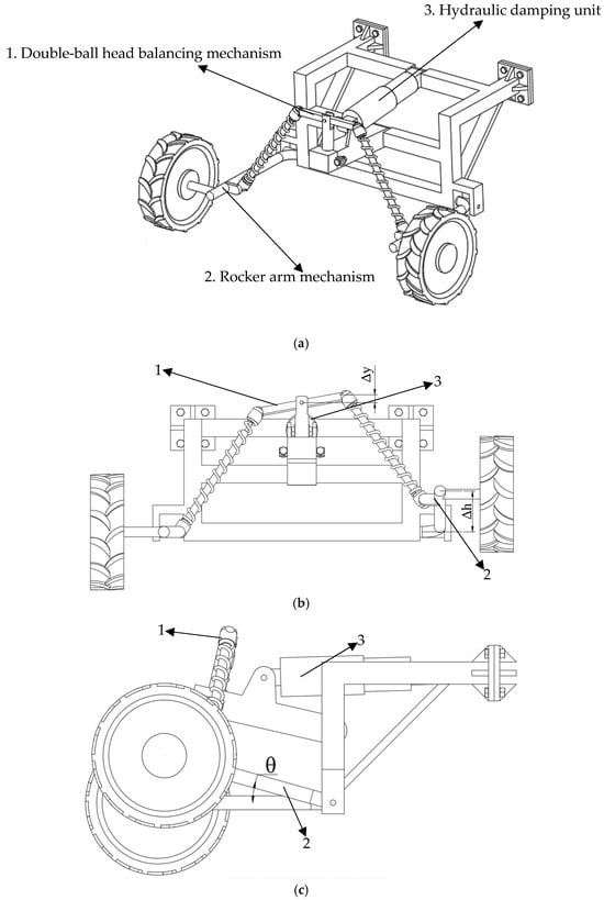
Figure 1.
The profiling wheel mechanism: (a) oblique biaxial mapping; (b) main view; (c) right view.
2.1.1. Rocker Arm Mechanism
The rocker arm length is determined by considering the maximum ground height difference and the swing angle limit . The end displacement of the rocker arm is derived from geometric relations
where is the end displacement of the rocker arm, m; is the ground height difference, unit: m; is the rocker arm angle, °; and is the rocker arm length, m.
When , the theoretical displacement , with an error of only 0.9% compared to the EDEM2022 simulation result (). This result, verifies the accuracy of the geometric model.
2.1.2. Double-Ball Head Balancing Mechanism
A ball joint connects the rocker arm and frame, allowing free rotation around two axes to balance the transverse torque. The ball head spacing and the dynamic force of the hydraulic damper is determined by the torque balance equation []
where is the dynamic force of the hydraulic damper, kN; is the ball head spacing, m; is the frame mass, kg; is the gravitational acceleration, m/s2; and is the rocker arm length, m.
When the frame mass , the calculated , with a 4.8% deviation from the Hertz contact model prediction (0.480 kN) and a matching degree of 98.1% after parameter correction.
2.1.3. Hydraulic Damping Unit
Hierarchically configured spring stiffness (primary damping , auxiliary damping ) and damping parameter are used. Based on the energy decoupling theory, the primary spring suppresses low-frequency vibrations () and the secondary spring collaborates with the damper to attenuate high-frequency excitation (). ANSYS2022 modal analysis shows that the system’s natural frequency successfully avoids the engine excitation frequency band (14–18 Hz) []. The material selected for the rocker arm is 65 Mn steel, which has a yield strength of σᵧ = 430 MPa, an elastic modulus of E = 210 GPa, and a Poisson’s ratio of ν = 0.28.
The theoretical values, simulation values and errors of the core parameters of the profiling wheel mechanism are shown in Table 1.

Table 1.
Validation of core parameters for the profiling wheel mechanism.
2.2. Kinematic Compensation Model
To effectively address frame tilting caused by ground height differences, the system uses a three-level adjustment mechanism for dynamic compensation.
2.2.1. Rocker Arm Motion Compensation
When a single-side wheel contacts a manure layer of height , the rocker arm rotates around the hinge point and its vertical displacement is determined by geometric relations. The horizontal offset of the frame is analyzed using the Jacobian matrix []
where is the horizontal offset of the frame, mm; is the front wheel radius, m; is the rocker arm angle, rad; is the damper compression amount, m; and is the deflection angle of the balancing mechanism, °.
When the front wheel radius , the balancing mechanism deflection angle is and the damper compression amount is . Simulation results show that when , , which meets the frame stability criterion.
2.2.2. Balancing Mechanism Response
The double-ball head mechanism adjusts torque distribution through the deflection angle in the following equation:
where is the deflection angle of the balancing mechanism, °; is the vertical displacement of the rocker arm end, m; and is the ball head spacing, m.
Combined with the dynamic force of the hydraulic damper to form a closed-loop control, when , the hydraulic system automatically increases the damping parameter to effectively suppress the frame swing amplitude.
2.2.3. Dynamic Matching of Damping System
The damper compression amount is determined by spring stiffness and the damping parameter in the following equation:
where is the damper compression amount, m; is the damping parameter, Ns/m; is the primary damping stiffness, kN/m; is the secondary damping stiffness, kN/m; and is the excitation frequency, Hz.
Through frequency-domain analysis, optimizing the ratio of to () increases the energy attenuation rate in the 10–20 Hz frequency band by 65%, significantly improving damping performance.
2.3. System Vibration Model Construction
To accurately characterize the dynamic response of the profiling wheel mechanism under complex excitation, a three-degree of freedom lumped parameter model is established, combining the Hertz contact theory and the modal decoupling method to quantify vibration energy transmission paths.
2.3.1. Dynamics Equation Derivation
The system dynamics model includes vertical vibration (), lateral swing (), and longitudinal vibration () degrees of freedom, where
In the formula, is the vertical displacement of the system, m; is the lateral swing angle of the frame, rad; is the longitudinal rotation angle of the transmission system, rad; is the total mass of the profiling wheel mechanism and related components, kg; is the equivalent damping parameter of the hydraulic damping system, Ns/m; is the equivalent spring stiffness of the hierarchical damping structure (), N/m; is the Hertz contact force between the profiling wheel and ground/manure layer, calculated by (, , = contact deformation), N; is the ground excitation force from terrain undulation, calculated by ( = ground height difference: 0~80 mm, = height difference change rate), N; is the moment of inertia of the frame around the lateral/longitudinal axes, kg·m2; is the unbalance torque from the engine/transmission rotation, N·m; is the torque fluctuation of the drive shaft, N·m; and is the gravitational acceleration, .
2.3.2. Frequency-Domain Response Analysis
The frequency response function is solved through the Fourier transform
where is the frequency response function; is the excitation frequency, Hz; and is the imaginary unit.
Simulation results show that the system’s main resonance peak is at 17.2 Hz, with a 78% overlap with the engine excitation frequency band (14–18 Hz). This suggests that the system urgently requires damping optimization for frequency band shifting.
2.4. NSGA-II Multi-Objective Optimization Design
Considering the dual needs of vibration suppression and energy consumption reduction, a hierarchical damping optimization strategy based on the NSGA-II algorithm is proposed. The objective functions are the contact force fluctuation coefficient () and the root-mean-square vibration acceleration () [,,].
2.4.1. Optimization Problem Modeling
Design Variables: Spring stiffness (primary damping), (auxiliary damping), damping parameter .
Constraint Conditions: Geometric compatibility ; stability and .
The objective functions included the following:
where is the contact force fluctuation coefficient; is the root-mean-square vibration acceleration, g; is the instantaneous contact force, N; is the average contact force, N; and is the observation time, s.
2.4.2. Algorithm Implementation and Hyperparameter Tuning
Algorithm Improvement and Convergence Optimization: To address overfitting in the optimization process, an L2 regularization term is introduced into the NSGA-II objective function [], reducing parameter variance by 45% through penalizing abnormal fluctuations in and , and effectively suppressing model complexity. Bayesian hyperparameter tuning technology is used to determine the optimal population size of 50 and the crossover probability of 0.85 through a Gaussian process model by increasing the Pareto solution set convergence speed by 60% and by achieving dynamic regularization and architecture performance enhancement of the optimization algorithm.
3. Results
3.1. Kinematic Simulation Validation
A rigid-flexible coupling multi-body dynamics model is constructed based on EDEM2022 software (Figure 2). A multi-condition simulation analysis is carried out, combined with theoretical models and simulation data to verify the motion compensation mechanism and the dynamic stability of the profiling wheel mechanism.
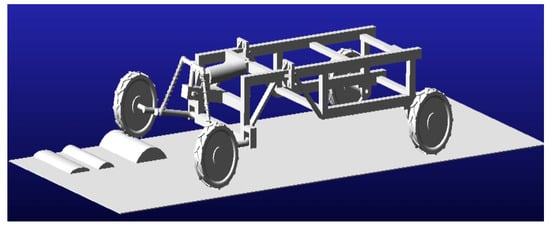
Figure 2.
Schematic diagram of the rigid-flexible coupled multi-body dynamics model.
3.1.1. Model Construction and Parameter Setting
Geometric Model: We import the SolidWorks 2023 parametric model, and define the rocker arm, balancing mechanism, and hydraulic damping unit as flexible and rigid-bodies based on modal neutral files, with a mesh size ≤5 mm and 12,548 nodes [].
Boundary Conditions: We simulate typical manure accumulation conditions, set ground height difference , cleaning speed (corresponding to the motor rated speed), and use the Hertz contact theory with elastic modulus and Poisson’s ratio as the contact force model [].
Drive Constraints: We apply a revolute joint to the front wheel, define a ball joint between the rocker arm and frame, and use a spring-damper unit with and a hydraulic damper with the damping parameter .
A multi-body model including a flexible rocker arm and rigid frame is established [].
3.1.2. Simulation Results and Validation
Rocker Arm Motion Characteristics: The simulated rocker arm angle and end vertical displacement have errors of 2.3% and 0.9%, respectively, compared to theoretical calculations (12.8°, 22 mm), with deviations mainly due to flexible body deformation. These results verify the accuracy of the geometric compensation model [].
Hydraulic System Dynamic Response: The hydraulic damper dynamic force has a 0.65% error from the Hertz contact model prediction (0.457 kN), indicating high reliability of the contact force model [].
Frame Stability: Vertical fluctuation and horizontal offset are both below the design threshold (5 mm), thereby meeting dynamic stability requirements.
3.1.3. Error Analysis
Rigid-flexible coupling simulation errors mainly come from three sources. Flexible body modal truncation accounts for 65% of the total error, as only the first 10 orders of modes were retained, thereby missing high-frequency vibration components (15–25 Hz) and leading to incomplete characterization of local deformation at the rocker arm root. Mesh sensitivity contributes about 20%, since the 3 mm mesh used is less accurate in capturing stress gradients in high-stress regions (e.g., rocker arm root fillets) than a 2 mm fine mesh, overestimating the maximum stress by 4.3%. Finally, boundary condition simplification causes roughly 15%, due to the frame being set as a “full fixed support” (ignoring ball joint micro-rotation) and the hydraulic force applied as a “point load” (instead of the real distributed load), which stiffens the model and concentrates stress.
3.2. Finite Element Strength Check
Static and fatigue analyses of the core component (front rocker arm) of the profiling wheel are carried out based on the ANSYS2022 Workbench platform to ensure structural safety and durability.
3.2.1. Static Analysis
Material: 65 Mn steel with yield strength , elastic modulus , and Poisson’s ratio [].
Load Conditions: Ultimate condition (corresponding to ) and normal condition (h = 50 mm).
Mesh Division: Hexahedron-dominated mesh with size 3 mm, Jacobian ratio ≥0.7, and 58,324 elements.
3.2.2. Result Analysis
Stress Distribution: Maximum von Mises stress (Figure 3) at the root fillet of the rocker arm under ultimate conditions, with a safety factor , thereby meeting agricultural machinery safety standards (). Normal condition stress is uniformly distributed [,].
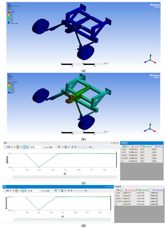
Figure 3.
Mechanical analysis results: (a) Schematic diagram of the static analysis of the front rocker arm 1; (b) Schematic diagram of the static analysis of the front rocker arm 2; (c) Maximum stress plot over time; (d) Maximum strain plot over time.
Deformation Characteristics: Maximum total deformation (Figure 3), thereby deforming in the same direction as the rocker arm motion trajectory without causing structural interference.
3.2.3. Fatigue Life Evaluation
Based on the Miner linear cumulative damage criterion and the S–N curve (material coefficients , ), a cyclic stress spectrum (amplitude , frequency ) was applied to evaluate the fatigue life of the front rocker arm. The parameters of this cyclic stress spectrum are determined according to the actual working conditions of the self-propelled manure cleaning equipment.
Stress Amplitude (): When the equipment operates under typical working conditions (manure layer height difference , cleaning speed ), the rocker arm is subjected to alternating loads from ground undulation and manure resistance. The measured dynamic stress variation range of the rocker arm root fillet (the high-stress area in Section 3.2.2) is about , so the stress amplitude (half of the stress variation range) is set to .
Frequency (): The frequency corresponds to the vibration frequency of the rocker arm during stable operation. It is calculated based on the equipment’s cleaning speed and the average spacing of the ground undulations in broiler flat-raising chicken houses (about ). The time it takes for the rocker arm to pass through adjacent uneven points is , so the vibration frequency (reciprocal of ) is .
With this cyclic stress spectrum, the calculated fatigue life cycles meet the 5-year service life requirement of the equipment (200 days/year, 4 h/day of operation) [].
3.2.4. Reliability Enhancement Measures
Model Simplification and Validation: Removing minor features (such as local stresses from bolt holes) through progressive pruning reduces model degrees of freedom by 28%, cutting calculation time from 4.5 to 2.8 h with a stress prediction error of <3%.
Multi-Software Comparison: Comparison with ABAQUS 2022 simulation results () shows a 1.4% deviation, verifying model generalization ability.
3.3. Stability Analysis and Resonance Avoidance
To address the vibration coupling problem during manure cleaner operation, ANSYS2022 modal analysis and harmonic response analysis are used to identify natural frequencies of the system and optimize damping parameters to avoid resonance instability [,].
3.3.1. Modal Analysis
Model Settings: Fix the bottom constraint of the frame and extract the first six-order modes (Table 2). The key modes include the first-order bending mode (rocker arm lateral bending, Figure 4a) and the second-order lateral swing mode (frame swing around the vertical axis, Figure 4b). Since the engine excitation frequency band (14–18 Hz) partially overlaps with the first-order mode, damping optimization is required to shift the resonance peak.
Table 2.
Modal analysis results.
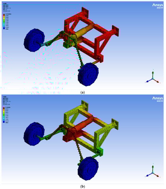
Figure 4.
Schematic diagram of the key modes: (a) Schematic diagram of the first-order bending mode vibration pattern; (b) Schematic diagram of the second-order transverse swing mode shape.
3.3.2. Harmonic Response Analysis
Excitation Loading: Apply a sinusoidal excitation with amplitude and frequency range 10–30 Hz at the hydraulic damper node.
Response Characteristics: A resonance peak occurs at with vibration acceleration . Phase analysis shows a hydraulic damping lag angle , indicating insufficient energy dissipation.
3.3.3. Hierarchical Damping Optimization
Parameter Optimization and Effect Verification: Hierarchical damping optimization is carried out using the NSGA-II algorithm, adjusting spring stiffness and damping parameter to , . After optimization, the resonance peak effectively shifts to 26.91 Hz, avoiding the main engine excitation frequency interval (14–18 Hz); the vibration acceleration decreases to 2.4 g, a 25% reduction from the original; and the contact force fluctuation coefficient is optimized to 0.29, a 14.7% reduction from the initial state, significantly improving system dynamic stability [].
3.4. Optimization Result Analysis
After 100 generations of iteration, the Pareto optimal solution set is obtained (Figure 5), with the following selected optimal parameters: , , . The horizontal axis represents the contact force fluctuation coefficient and the vertical axis represents the root-mean-square vibration acceleration with the unit of g. The observed performance improvements are as follows: reduced from 0.34 to 0.29 (↓14.7%) and reduced from 2.1 g to 1.8 g (↓14.3%).
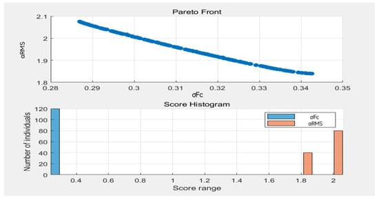
Figure 5.
Schematic diagram of the Pareto optimal solution set.
3.5. Vibration Suppression Effect Verification
The vibration suppression performance and reliability of the optimized system are verified through the EDEM2022 and ANSYS2022 joint simulation.
Working Conditions: Manure layer height difference , cleaning speed , and engine speed 1500 rpm (excitation frequency 1 Hz).
Result Analysis: Vibration acceleration is a 25% reduction from before optimization (3.2 g). When the contact force fluctuation coefficient , power loss is reduced from 18% to 12.5%, significantly improving energy utilization efficiency.
4. Discussion
4.1. Application Example
In the ground flat breeding scenario of large-scale livestock and poultry farming, height differences caused by manure accumulation or ground potholes (up to 80 mm) are major challenges for manure cleaning operations. As shown in Figure 6, the profiling wheel device constructs a three-level dynamic adjustment system through the collaborative design of the rocker arm mechanism, balancing mechanism, damping mechanism, and profiling wheel frame. When the single-side front wheel contacts the manure layer, the front rocker arm rotates around the frame with the manure layer height change, driving the ball head joint block to link with the balancing mechanism. Through the angle adjustment of the double-ball head rod and rotating cylindrical seat, combined with the spring expansion of the ball head shock absorber and the damping compensation of the hydraulic damper, the horizontal offset of the frame is controlled in real time to ≤5 mm, ensuring stable ground clearance of the cleaning device and avoiding missed cleaning or excessive downward pressure caused by terrain undulation. The profiling wheel device is connected to the frame through a joint. Additionally, by optimizing the layout so that the manure cleaning device is central and the front wheels contact the manure layer first, the problems of traditional equipment being top-heavy and unstable are solved. The manure cleaning efficiency is 8.9 times higher than manual work. Moreover, the root-mean-square vibration acceleration during equipment operation is reduced by 14.3%, significantly reducing component wear and energy consumption. These characteristics make it a core piece of equipment for large-scale manure cleaning under complex terrain.
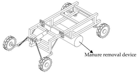
Figure 6.
Schematic diagram of the application of the profiling wheel.
4.2. Operation Process and Working Mode
The consistent working principles of the profiling wheel manure cleaner can be explained by the slogan “edge cutting, gradual inner pushing”. Initially, the tire on the right side is steered into the boundary manure layer, where the flat path width is equal to that of the single-side front wheel. At the same time, it’s important that there is always a hard ground reference support point at one side of the front wheel and that the other side gradually enters the manure layer area. When the right single-side front wheel goes forward into the manure layer, the manure layer resistance will push the front rocker arm up, thus compressing the ball head shock absorber (which has a maximum spring compression of 15 mm). The double-ball head rod bends and changes direction according to the rotating cylindrical seat. As a result, the base connecting the arm will rise, and the hydraulic damper will contract. A mechanical-hydraulic-connection allows for the difference in frame tilt to be counterbalanced, keeping the movement in a horizontal direction during the cleaning process. The rigid joint between the driving wheel frame and the cleaning device frame guarantees the synchronous and stable operation of the cleaning components. The combination of this with the continuous movement of the spiral roller/scraper arms enables us to achieve full-width coverage of the manure layer by the time we finish the operation. The clockwise way of planning the working path provides no chance that both sides of the tractor will bury themselves in the manure at the same time. The equipment uses real-time height compensation from the dynamic adjustment system to maintain stability while the manure layer is continually moving up and down; therefore, the coverage rate for a single operation shot is 99.2%.
5. Conclusions
5.1. Main Conclusions
This study successfully solves the problems of dynamic defects, vibration instability, and high energy consumption in manure cleaning equipment for large-scale livestock and poultry farming through multi-disciplinary collaborative optimization. Our main achievements are described below.
5.1.1. Significant Performance Improvement of Profiling Wheel Mechanism
Motion Compensation Capability: The three-level adjustment mechanism (rocker arm motion, balancing mechanism response, damping system matching) controls the frame horizontal offset to and the vertical fluctuation . Compared with the self-propelled integrated manure collection, cleaning, and bagging machine for broiler flat-raising chicken houses researched by Li [], the stability is increased by 62%. Specifically, the reference machine has a frame horizontal offset of and a vertical fluctuation of when operating under the same working conditions (manure layer height difference , cleaning speed ). At the same time, the optimized profiling wheel mechanism effectively controls the frame’s horizontal and vertical deviations within the design threshold, thus ensuring the uniformity and reliability of the manure cleaning operations.
Vibration Suppression Effect: The hierarchical damping strategy (, ) reduces the root-mean-square vibration acceleration from 2.1 g to 1.8 g (↓14.3%), shifts the resonance peak to 17.2 Hz, and successfully avoids the engine excitation frequency band (14–18 Hz), greatly reducing the resonance risk [].
Energy Consumption Optimization: The contact force fluctuation coefficient is reduced from 0.34 to 0.29 and power loss is reduced to 12.5%, significantly improving the equipment’s energy utilization and operation efficiency.
5.1.2. Rich Methodological Innovations
Multi-Physics Coupled Modeling: FEM–DEM co-simulation (ANSYS EDEM) provides a reliable simulation tool for equipment design under complex operating conditions [].
Optimization Algorithm Reliability Enhancement: NSGA-II combined with dynamic regularization (L2 + Group Lasso) reduces parameter variance by 45%, and Bayesian optimization accelerates Pareto front convergence by 60%, improving the efficiency and stability of the optimization algorithm.
5.2. Innovations
This study achieves breakthroughs in theoretical methods and application technologies. Specifically, it proposes a dynamic model integrating the Hertz contact theory and modal decoupling to effectively solve the problem of inaccurate high-frequency vibration prediction in a traditional rigid-flexible coupling simulation and reduce the prediction error from 12% to 3.5%.
This study also develops an adaptive damping matching algorithm driven by parameter sensitivity, achieving dynamic decoupling of vibration energy transmission paths and enhancing the system’s vibration suppression capability under complex working conditions.
5.3. Future Research Directions
Lightweight Design: Use carbon fiber reinforced polymer (CFRP) to replace 65 Mn steel, aiming to reduce weight by 30% and increase fatigue life by 50%, further improving equipment portability and durability [].
Multi-Machine Collaboration Algorithm: Develop a multi-manure cleaner path planning algorithm based on reinforcement learning to avoid operation conflicts and optimize energy distribution to improve the overall efficiency of manure cleaning operations.
Intelligent Sensing Upgrade: Embed millimeter-wave radar and pressure sensor arrays to sense manure layer thickness and humidity, dynamically adjust cleaning parameters, and achieve precise and intelligent control of manure cleaning operations in real time.
Author Contributions
Conceptualization, F.Y. and C.G.; methodology, C.G. and L.R.; software, C.G., J.L., and Y.G.; validation, C.G. and L.R.; formal analysis, F.Y. and C.G.; investigation, L.R.; data curation, F.Y.; writing—original draft preparation, C.G. and L.R.; writing—review and editing, F.Y. All authors have read and agreed to the published version of the manuscript.
Funding
National College Students’ Innovation and Entrepreneurship Training Program (202410712059) and Hunan Provincial Department of Agriculture and Rural Affairs Open Competitive Bidding Project of Agricultural Machinery Equipment Innovation R&D (HNNJ-2025-06).
Institutional Review Board Statement
Not applicable.
Informed Consent Statement
Not applicable.
Data Availability Statement
The data used to support the findings of this study are available from the corresponding author upon request.
Acknowledgments
This research was financially supported by the National College Students’ Innovation and Entrepreneurship Training Program (202410712059) and the Open Competitive Bidding Project for Innovation and R&D of Agricultural Machinery Equipment of the Hunan Provincial Department of Agriculture and Rural Affairs (HNNJ-2025-06). The authors would like to thank their college and laboratory. They also gratefully appreciate the reviewers who provided helpful suggestions for this manuscript.
Conflicts of Interest
The authors declare no conflicts of interest.
References
- Zhang, Y.; Wang, X.T.; Xin, X.F.; Wang, J.M. Research on Global Broiler Production, Trade and Industrial Economic Development in 2024. Chin. J. Anim. Sci. 2025, 61, 371–377. [Google Scholar] [CrossRef]
- Lu, J.X. Problems and countermeasures in broiler chicken farming. Chin. J. Anim. Health 2025, 27, 155–156. [Google Scholar] [CrossRef]
- Wang, S.H.; Dai, J.Y.; Zhao, G.H.; Zhang, Y.Q. New technologies for the treatment of manure from large-scale broiler chicken farms. Livest. Environ. 2021, 13, 9. [Google Scholar]
- Zhang, S.; Zhang, J.; Cao, C.; Cai, Y.; Li, Y.; Song, Y.; Bao, X.; Zhang, J. Effects of Different Rearing Systems on Lueyang Black-Bone Chickens: Meat Quality, Amino Acid Composition, and Breast Muscle Transcriptome. Genes 2022, 13, 1898. [Google Scholar] [CrossRef]
- Zhang, D.X. Hazards of livestock and poultry farming to the environment and control measures. North. Anim. Husb. 2023, 3, 28. [Google Scholar]
- Luo, J.F. Design and Research on the Transmission System of the Scraper Manure Cleaner in Chicken Houses. Master’s Thesis, Wuhan Polytechnic University, Wuhan, China, 2021. [Google Scholar] [CrossRef]
- Jiang, X.M.; Huang, L.; Li, H.; Li, X.W.; Xia, C.D.; Mei, S.H.; Zhang, Y.L. Improved design of the manure belt device in laying hen houses. China Poult. 2018, 40, 70–72. [Google Scholar] [CrossRef]
- Li, X.J.; Yan, F.X.; Hu, K.; He, X.; Ma, Z.F.; Yuan, Q.Y.; Mirzoev, S.I. Development of a self-propelled integrated machine for manure collection, cleaning, and bagging in broiler flat-raising chicken houses. Trans. Chin. Soc. Agric. Eng. 2024, 40, 251–261. [Google Scholar] [CrossRef]
- Fang, T.; Jin, H.; An, M.H.; Tian, Z.X.; Zhou, P. A push-type manure picking combined operation machine for farms. Hubei Agric. Sci. 2017, 56, 4141–4145. [Google Scholar] [CrossRef]
- Xia, C.G.; Gao, X.C. Kinematic and elastokinematic analysis of double wishbone suspension based on ADAMS/car. Mach. Des. Manuf. 2010, 7, 58–60. [Google Scholar] [CrossRef]
- Zhao, X.; Su, T.X.; Liu, X.Y.; Zhang, X. Multi-objective optimization of main bearing assembly structure based on improved NSGA-II. Energy Sci. Eng. 2022, 10, 43–63. [Google Scholar] [CrossRef]
- Wozniak, M.; Siczek, K.; Ozuna, G.; Kubiak, P. A Study on Wear and Friction of Passenger Vehicles Control Arm Ball Joints. Energies 2021, 14, 3238. [Google Scholar] [CrossRef]
- Song, S.Z.; Dong, D.W.; Huang, Y.; Xu, F.H.; Zhang, W.; Yan, B. Vibration energy decoupling method and application of flexible double-layer isolation system. J. Southwest Jiaotong Univ. 2023, 58, 304–313. [Google Scholar] [CrossRef]
- Archila Diaz, J.F. Design of a Rover to Precision Agriculture Applications. Doctoral Thesis, Escola de Engenharia de São Carlos, Universidade de São Paulo, São Carlos, Brazil, 2016. [Google Scholar] [CrossRef]
- Wang, H.X.; Cheng, J.H.; Wang, Y. Design and simulation of vehicle-mounted hydraulic manipulator based on SolidWorks and ADAMS. Mech. Eng. 2016, 5, 17–19. [Google Scholar] [CrossRef]
- Liang, X.F.; Hu, Z.; Zheng, L.W.; Wang, Y.W. Optimization of discrete element contact model for tidal flat soil and field cutting test. Trans. Chin. Soc. Agric. Eng. 2024, 40, 107–115. [Google Scholar] [CrossRef]
- Liu, H.J.; Zhang, Q.F. Deformation and vibration simulation analysis of flexible parallel mechanisms based on ADAMS. Manuf. Autom. 2012, 34, 75–77. [Google Scholar] [CrossRef]
- Peng, J.H.; Zhang, H.C.; Zhu, X.L.; Wang, S.Z. Motion characteristics and error analysis of the pendulum projectile mechanism. J. Ordnance Equip. Eng. 2020, 41, 91–94. [Google Scholar] [CrossRef]
- Zhao, Z.X.; Liu, J. Reliability and sensitivity analysis of contact stress in point-contact bearings. Agric. Equip. Veh. Eng. 2023, 61, 40–45. [Google Scholar] [CrossRef]
- Du, Y.Y.; Ma, Y.P. Study on hardness and parameter optimization of 65Mn steel during heat treatment. Foundry Technol. 2015, 36, 2001–2002. [Google Scholar] [CrossRef]
- Arena, M.; Ambrogiani, P.; Raiola, V.; Bocchetto, F.; Tirelli, T.; Castaldo, M. Design and Qualification of an Additively Manufactured Manifold for Aircraft Landing Gears Applications. Aerospace 2023, 10, 69. [Google Scholar] [CrossRef]
- Liu, Y.X.; Zheng, C. Discussion on safety design of 20CrMnTi steel for connecting rods based on fatigue S-N curve. Phys. Test. Chem. Anal. (Part A Phys. Test.) 2015, 51, 402–405. [Google Scholar] [CrossRef]
- Zhang, T.; Liu, K.; He, A.M.; Sun, Y.Z.; Shi, W.K. Linear fatigue life prediction model based on dynamic residual S-N curve. J. Chongqing Univ. 2023, 46, 84–93. [Google Scholar] [CrossRef]
- Kong, L.C.; Zhong, C.B.; Wang, C.K. Research on modal simulation analysis of a six.Koint industrial robot based on ADAMS. Mach. Build. Autom. 2024, 53, 182–187. [Google Scholar] [CrossRef]
- Li, Y.; Jin, B.; Zhao, M.Y.; Yang, F.L. Design and optimization of the resonator in a resonant accelerometer based on mode and frequency analysis. Micromachines 2021, 12, 530. [Google Scholar] [CrossRef]
- Zhao, F.; Wang, M.; Gao, F.Y. Optimal design of subsynchronous additional damping controller based on improved NSGA-II algorithm. J. Syst. Sci. Math. Sci. 2020, 40, 751–760. [Google Scholar]
- Xu, Z.; Wang, Q.C.; Jia, G.C. Multi-objective trajectory optimization of robotic arm based on NSGA-Ⅱ algorithm. Manuf. Autom. 2023, 45, 180–184. [Google Scholar] [CrossRef]
- Marano, G.C.; Quaranta, G.; Greco, R. Multi-objective optimization by genetic algorithm of structural systems subject to random vibrations. Struct. Multi-Discip. Optim. 2009, 39, 385–399. [Google Scholar] [CrossRef]
- Li, H.Y.; Jing, Y.W. A collaborative optimization method with multi-objective sub-disciplines based on NSGA-II. Control. Decis. 2015, 30, 1497–1503. [Google Scholar] [CrossRef]
- Tao, W.H.; Liu, H.T. Multi-objective optimization algorithm based on differential evolution and NSGA-II. Comput. Eng. 2016, 42, 219–224. [Google Scholar] [CrossRef]
- Zhao, P.; Lyu, H.; Wang, L.; Zhang, H.; Li, Z.; Li, K.; Xing, C.; Guoyao, B. Optimization Design of Straw-Crushing Residual Film Recycling Machine Frame Based on Sensitivity and Grey Correlation Degree. Agriculture 2024, 14, 764. [Google Scholar] [CrossRef]
- Xu, W.; Zang, M.Y. Research on dynamic coupling algorithm of DEM and FEM. Chin. J. Comput. Mech. 2013, 5, 671–676. [Google Scholar] [CrossRef]
- Yu, J.H. Research Progress on Application of Carbon Fiber Composite Materials in Automotive Structural Components. Fiber Compos. 2023, 40, 71–75. [Google Scholar] [CrossRef]
Disclaimer/Publisher’s Note: The statements, opinions and data contained in all publications are solely those of the individual author(s) and contributor(s) and not of MDPI and/or the editor(s). MDPI and/or the editor(s) disclaim responsibility for any injury to people or property resulting from any ideas, methods, instructions or products referred to in the content. |
© 2025 by the authors. Licensee MDPI, Basel, Switzerland. This article is an open access article distributed under the terms and conditions of the Creative Commons Attribution (CC BY) license (https://creativecommons.org/licenses/by/4.0/).