Article

Lyapunov-Based Pitch Control for Electric Vehicles Using In-Wheel Motors

by
Andrew Valdivieso-Soto
1,
Renato Galluzzi
1,*,
Eugenio Tramacere
2,
Riccardo Cespi
3 and
Luis M. Castellanos Molina
2
1
School of Engineering and Sciences, Tecnologico de Monterrey, Mexico City 14380, Mexico
2
Department of Mechanical and Aerospace Engineering, Politecnico di Torino, 10129 Turin, Italy
3
School of Engineering and Sciences, Tecnologico de Monterrey, Monterrey 64849, Mexico
*
Author to whom correspondence should be addressed.
Vehicles 2025, 7(2), 37; https://doi.org/10.3390/vehicles7020037 (registering DOI)
Submission received: 12 March 2025 / Revised: 24 April 2025 / Accepted: 25 April 2025 / Published: 26 April 2025

Abstract

:
Modern powertrain configurations for electric vehicles introduce the possibility to actuate the wheel directly by means of in-wheel motors. These machines enable stiffer and more efficient traction, with the possibility of introducing pitch motion control due to the intrinsic coupling between longitudinal, vertical, and pitch dynamics. This paper proposes a pitch rate attenuation control exploiting a Lyapunov function that attempts to cancel the pitch rate dynamics from the model. Unlike previous works, this pitch control is performed exclusively with the traction machine; it does not rely on controllable suspension systems. The controller formulation guarantees global stability of the vehicle. Furthermore, it considers the nonlinearity of the plant introduced by the dependency on the pitch angle. To facilitate the feedback of the road profile needed by the Lyapunov controller, two Kalman filters are included in the control law. This work implements the described strategy on a half car model. Simulations examine different speed and road conditions. It is demonstrated that the control strategy can blend longitudinal and pitch rate attenuation torque commands using a rear in-wheel motor, attaining a reduction of up to 41 % for chassis pitch rate and 36 % for pitch acceleration.

1. Introduction

In recent years, electric vehicles (EVs) have emerged as an alternative to fossil fuel-based transportation. EVs present different traction architectures, such as one or two central motors, or in-wheel motors. Centralized approaches tackle one or two axles at a time; they require a transmission system with gearbox and differential units. These mechanisms involve maintenance and an overall larger vehicle weight [1].
To enhance the performance EVs and avoid these problems, the in-wheel motor (IWM) placed directly into the rim of the wheel is a possible solution. IWMs provide substantial benefits to the vehicle powertrain, such as direct drive traction without transmission mechanisms, volume reduction, and better drivability [2,3]. An IWM powertrain attains a quick and accurate torque response, together with individual wheel motor control [4]. When compared to central electric motors, their footprint is relatively compact. Hence, space within the vehicle chassis is increased to include other systems, such as larger batteries or a more spacious cabin for passenger comfort [1]. Furthermore, the addition of IWM helps to increase efficiency by between 5 % and 6 % due to the lack of mechanical losses [2,3,5]. This mechanical advantage comes with a reduction of overall noise levels inside the cabin.
From an actuation standpoint, the transmission from the IWM to the wheel is stiffer than in any other centralized configuration, bringing the advantage of improved control bandwidth [1]. The modularity of the two- or four-wheel drive and the independent controllability allows cornering performance, torque vectoring, regenerative braking, or ABS to be handled more efficiently [3,6]. A disadvantage of IWMs is the deterioration of vertical and pitch dynamics performance due to the increased unsprung mass [5,7].
The aforementioned advantages have pushed research efforts towards the use of IWMs for traction control. Guo et al. studied the influence of IWMs in the longitudinal and vertical degrees of freedom of a half car model [8]. In [9], the authors designed a slip controller using model predictive control (MPC) to improve tire adhesion to uneven surfaces. Feng et al. tested a torque vectoring control strategy together with active suspensions using MPC [10]. Li et al. analyzed the vibration effect of the unbalanced magnetic force of the IWM under unsteady conditions [11]. Xu et al. coordinate friction braking and regenerative braking to improve traction performance using IWMs [12]. Vidal et al. designed a nonlinear model predictive control (NMPC) for a four-wheel-drive EV to attenuate oscillations caused by irregular road profiles [13]. Wang et al. proposed an integrated controller for a four-wheel-steering, four-wheel-drive vehicle with active suspension [14]. It considers handling, comfort, lateral stability, and anti-rollover features.
Due to the independent corner control with IWMs, several research works have dealt with torque vectoring using these machines. In [15], the authors proposed two MPCs for yaw stabilizing and energy-efficient torque vectoring of four IWM electric vehicles. Authors in [16] designed a torque vectoring control for two IWM in the rear axle to enhance the vehicle maneuverability. Asperti et al. [17] proposed torque vectoring to enhance vehicle handling while maintaining high energy efficiency levels. Hou et al. used a hierarchical electronic stability control strategy for four IWM independent drive electric vehicles to enhance yaw rate and side-slip angle [18]. Guo et al. [19] applied a hierarchical control to use the four IWM to enhance maneuverability and stability under emergency conditions. A lateral stability controller with sliding mode control is described in [20]. It employed four independent IWMs to enhance trajectory tracking. Xu et al. designed an MPC for velocity-tracking to improve energy recovery through regenerative braking with IWMs [21]. In addition, Yim [22] integrated chassis control to enhance both maneuverability and lateral stability. Chae et al. [23] proposed a sliding mode controller to improve the handling performance of an electric vehicle equipped with an IWM. Yu [24] et al. analyzed the coupling relationship of electronic power steering and torque vectoring control. In [25], Jeong et al. designed a path-tracking control for IWM with independent steering, driving, and braking systems using a pure pursuit control. Lin et al., proposed a multi-objective optimization MPC for a hierarchical torque distribution considering vehicle stability and energy consumption [26]. Tian et al. designed a differential driving torque with the front and rear wheels as the control inputs [27].
The coupled nature between longitudinal, vertical, and pitch dynamics implies an influence of braking and acceleration actions on ride comfort features, specifically affecting the pitch angle. Previous works have addressed this phenomenon. A ride blending control was introduced in [28], focused on pitch, roll, and heave suppression. This proposal employed two proportional–integral (PI) algorithms to split the control actions on the active suspension system and the electronic braking of an IWM. Kanchwala and Widenberg [29] used a proportional–derivative (PD) control to enhance the pitch reduction on the vehicle body during braking. The proposal showed limited pitch attenuation throughout the tested duty cycle. Fujimoto and Sato [4] developed a pitching control for IWMs to improve passenger comfort during deceleration. It used PD and PI controllers for pitch angle and pitch rate attenuation, respectively. This study demonstrated the reduction of pitch variables, but it did not study passenger comfort. Yu et al. [30] analyzed the torque distribution system with dual-motor centralized vehicles targeting pitch performance. Their method, based on MPC, reduced pitch motion during acceleration and braking, albeit a limited bandwidth due to the centralized powertrain configuration. In [5], the authors proposed a pitch control for IWM tested with straight-line acceleration driving on an uneven road. They demonstrated a reduction in pitch vibration using a PI control and linear longitudinal acceleration. Bunlapyanan et al. analyzed the use of four IWMs controlled via a proportional strategy to improve passenger comfort. Their results showed that the IWMs effectively reduced the vertical acceleration of the sprung mass at a constant longitudinal speed [31].
The literature shows that many of the efforts that attempt pitch control using the intrinsic coupling with longitudinal dynamics actuation rely on secondary subsystems, such as active suspensions, to accomplish the desired performance. Furthermore, in many of the works, proportional–integral–derivative (PID) and its variants are applied to a plant that is intrinsically nonlinear. This work presents a Lyapunov-based control law to attenuate the pitch rate behavior by actuating rear-axle IWMs on a vehicle. This approach guarantees the global stability of the closed-loop system, as its synthesis takes into account the nonlinear plant model, constituted by a half car coupling longitudinal and vertical dynamics. Furthermore, road disturbances are known to the control strategy thanks to the implementation of a road profile observer.
The sequel of this paper is organized as follows. Section 2 describes the vehicle model used in this paper. Section 3 outlines the controller design and describes the road profile estimation. Simulation results validate the proposed strategy in Section 4. Finally, Section 5 concludes the work.

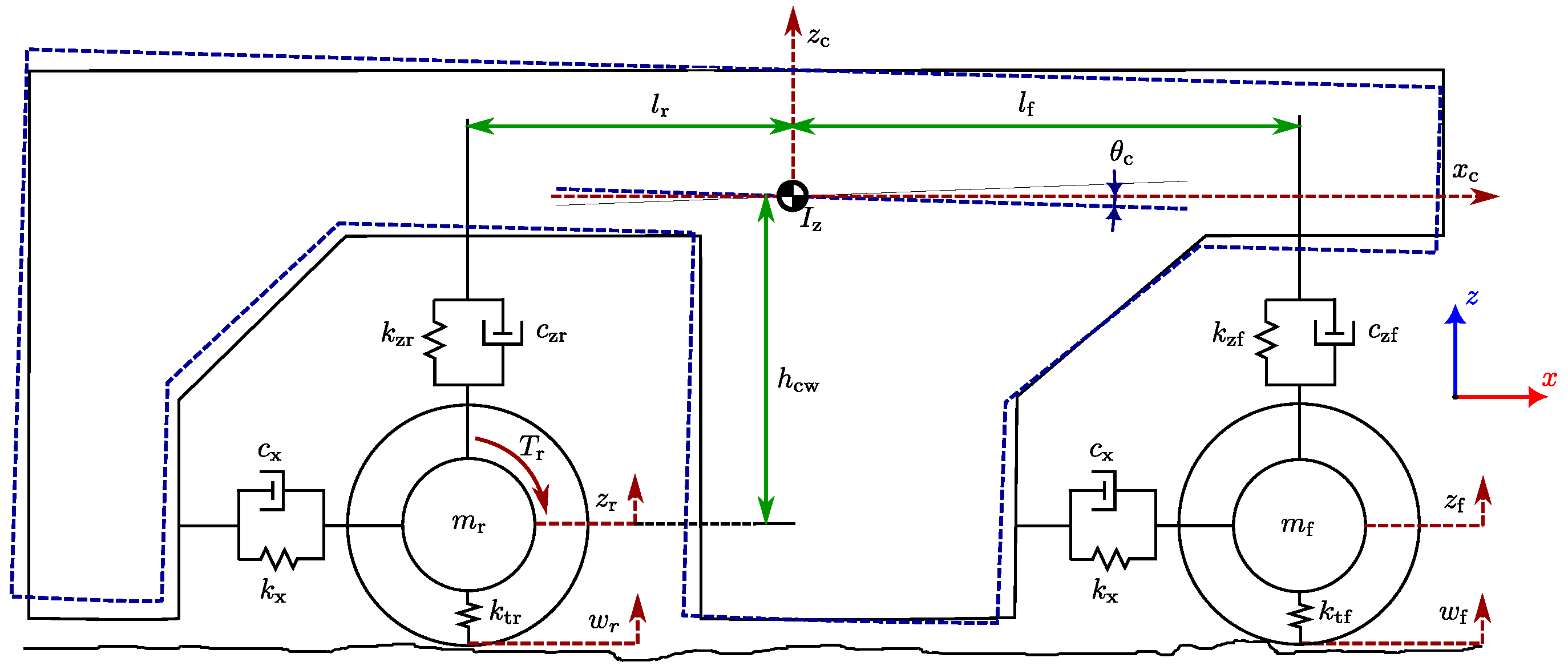
2. Vertical, Pitch, and Longitudinal Vehicle Dynamics

A vehicle model is required to capture the interaction between vertical, pitch, and longitudinal dynamics, with the IWM playing a central role [8,13,32]. To this end, a half car dynamic model is employed in this study, as illustrated in Figure 1. In addition to providing traction, the IWM contributes to pitch rate attenuation, eliminating the need for an active suspension system. This vehicle plant model ensures the reproduction of vehicle dynamics in the degrees of freedom relevant to the actuation principle. Note that including other degrees of freedom, such as roll and yaw, could influence the behavior of the longitudinal, vertical, and pitch dynamics exclusively as external perturbations. However, for simplicity, the used formulation neglects those secondary components.

2.1. Suspension Forces

Components F kx i and F cx i represent the support forces in the longitudinal degree of freedom. They incorporate elastic and dissipative contributions. The subscript i = f , r denotes the front or rear axle, respectively. These forces are defined as
F cx i = c x x ˙ c x ˙ i + z c z i + h cw θ ˙ c cos θ c
F kx i = k x x c x i + z c z i + h cw sin θ c
Longitudinal damping and stiffness coefficients are denoted by c x and k x , respectively. Along the longitudinal axis, x c is the displacement of the vehicle body, and x i is the longitudinal displacement of each axle. Similarly, z c denotes the vertical displacement of the vehicle body at the center of gravity (CoG), whereas z i represents the vertical displacement at each axle. The height h cw is the vertical distance between the vehicle CoG and the wheel center, where the longitudinal forces are applied. Finally, θ c denotes the pitch angle. Equations (1) and (2) couple longitudinal and vertical displacements and speeds through pitch motion.
This formulation also includes suspension forces in the vertical degrees of freedom. In this case, equations differ between axles:
F cz i = c z i z ˙ c z ˙ i + s i x c x i + l i θ ˙ cos θ c
F kz i = k z i z c z i + s i x c x i + l i sin θ c
In this context, s r = + 1 and s f = 1 are used to reflect the opposing behavior of the front and rear suspensions i.e., when the front suspension extends, the rear one compresses, and vice versa. Each axle’s suspension is defined by a spring stiffness k z i and a damping coefficient c z i . The parameter l i represents the fixed distance from the vehicle CoG to each axle. Like the longitudinal case, Equations (3) and (4) include a displacement term in the vertical direction, accounting for the effect of pitch angle and angular rate on longitudinal displacement.

2.2. Vertical Dynamics

Equations (3) and (4) define the suspension forces used to establish the dynamic force equilibrium for both unsprung masses:
m i z ¨ i = F cz i + F kz i k t i ( z i w i )
where m i is the wheel hub total mass including the IWM, k t i is the tire stiffness, and w i is the vertical road excitation at the wheel.
Similarly, the vertical acceleration of the vehicle body (mass m c ) is governed by
m c z ¨ c = F czf F czr F kzf F kzr
where z ¨ c is the vertical acceleration of the sprung mass. The vertical acceleration at the vehicle corners can be calculated as a nonlinear function of the generalized coordinates:
z ¨ c i = z ¨ c + s i l i θ ¨ c cos θ c θ ˙ c 2 sin θ c

2.3. Longitudinal Dynamics

This formulation computes the dynamic force equilibrium for the front and rear axles, respectively:
m f x ¨ f = F cxf + F kxf F roll , f
m r x ¨ r = F cxr + F kxr + T r R lad , r F roll , r
For the rear axle, T r is the traction torque provided by the IWM (rear wheel drive), and R lad , r is the laden rear wheel radius. Note that in this formulation, propulsion force is transmitted ideally by the wheel through pure rolling. This choice simplifies the formulation of the control strategy. However, testing will be performed by accounting wheel slip.
Rolling resistance forces of both axles are expressed as
F roll , f = f roll m c l r l f + l r g sign ( x ˙ c )
F roll , r = f roll m c l f l f + l r g sign ( x ˙ c )
where g is the gravitational acceleration, and f roll is the rolling resistance coefficient given by
f roll = f 0 + f 2 x ˙ c 2
with zero- and second-degree polynomial coefficients f 0 and f 2 .
Equation (13) defines the longitudinal acceleration for the sprung mass, which accounts for the contributions of the spring and damper forces at both the front and rear axles:
m c x ¨ c = F cxf F cxr F kxf F kxr F a m c g sin α
where α is the angle of inclination of the road.
The aerodynamic drag force F a is governed by
F a = 1 2 ρ C d A c x ˙ c 2 sign ( x ˙ c )
where ρ is the mass density of the air, C d is the aerodynamic drag coefficient and A c is the frontal area of the vehicle.

2.4. Pitch Dynamics

Moment equilibrium around the vehicle CoG quantifies pitch dynamics θ c . Incorporating the moment of inertia I z , the resulting equation is obtained as follows:
I z θ ¨ c = d xf ( F czf + F kzf ) d xr ( F czr + F kzr ) + d zf ( F cxf + F kxf ) + d zr ( F cxr + F kxr )
To account for the influence of road roughness excitation and IWM torque on pitch dynamics, the forces F czf , F czr , F cxf , and F cxr are substituted using Equations (5), (8), and (9), leading to the final expression for pitch dynamics:
I z θ ¨ c = d xf m f z ¨ f + k t f ( z f w f ) d xr m r z ¨ r + k t r ( z r w r ) + d zf m f x ¨ f + F roll , f + d zr m r x ¨ r T r R lad , r + F roll , r
For simplicity, auxiliary distances d z i and d x i are used:
d z i = z c z i + h cw
d x i = x c x i + l i

2.5. In-Wheel Motor

The IWM is the actuator responsible for ensuring traction and attenuating pitch variations in the vehicle. The IWM exhibits saturation governed by the maximum torque-speed characteristic shown in Figure 2. The machine presents a torque limit ( 1650 Nm ) from stall up to the base speed ( 500 r / min ). Due to battery voltage limitations, the machine is then constrained in power by means of field weakening ( 84 kW ), until it reaches its maximum operating speed ( 1300 r / min ). The outlined characteristic appears symmetrically in the first and fourth quadrants of the torque-speed plane. The use of a half car model allows integrating only one IWM for rear traction.
The dynamic response of the IWM is modeled as a first-order low-pass filter with time constant τ :
T r = 1 τ s + 1 · T ref
where T ref is the motor torque command, and T r is the actual rear motor torque.

2.6. Road Roughness

To reproduce a reliable road profile waveform, a probabilistic approach was followed using the ISO 8608 standard [33]. A unit-power white noise signal generates the road roughness disturbance. The road profile speed waveform can be written for both wheels [34] as
w ˙ i ( t ) = 2 π f 3 w i ( t ) + 2 π G r x ˙ c · n ( t )
where n ( t ) is the white noise signal with unit power, f 3 is the cut-off frequency, and G r is the road roughness index.

3. Pitch Rate Attenuation Control

The pitch rate attenuation control strategy, which is the main objective of this work, uses a single rear axle IWM in a half car. The selection of the Lyapunov control approach suits nonlinear system control and ensures stability.
The Lyapunov control candidate to attenuate the pitch rate is given by
V = 1 2 r 2
where the pitch error is defined as
r = θ ˙ ref θ ˙ c
and θ ˙ ref , θ ˙ c are the pitch rate reference and measurement, respectively.
The time derivative of V must fulfill
V ˙ = r r ˙ = κ V
where κ > 0 is the nonlinear controller gain. Substituting (21) into (23) and enforcing the pitch rate reference to zero yields
θ ¨ c = κ 2 θ ˙ c
Expression (24) can be substituted into (16). Then, the motor torque command for pitch rate attenuation is calculated:
T θ ˙ = { κ 2 I z θ ˙ c + d xf m f z ¨ f + k t f ( z f w f ) d xr m r z ¨ r + k t r ( z r w r ) + d zf m f x ¨ f + F roll , f + d zr m r x ¨ r + F roll , r } R lad , r d zr
This control law depends on knowing the vertical and longitudinal accelerations and positions of the unsprung masses ( z ¨ i , x ¨ i , z i , x i ), alongside the chassis longitudinal speed and its vertical and longitudinal positions ( x ˙ c , x c , z c ), and the chassis pitch rate ( θ ˙ c ). These quantities are necessary for implementing the control strategy and can typically be obtained through onboard inertial sensors. Using this information, the rear in-wheel motor is controlled by applying a torque T r as described in Equation (25). However, to apply this strategy, the road profile displacement for both axles ( w i ) is also needed, which highlights the necessity of a road profile estimation method.

3.1. Road Profile Estimation

A continuous Kalman filter estimates the road profile on each corner [35,36]. The vertical acceleration and position is extracted at the chassis level, for front and rear corners ( z ¨ c i , z c i ). The suspension deflection is also used for each case i.e., z c i z i . The formulation of the filter requires a quarter car representation for each axle in state-space form:
ξ ˙ i = A i ξ i
y i = H i ξ i
where ξ i = [ z c i z ˙ c i z i z ˙ i w i w ˙ i ] is the state vector. The state and observation matrices are respectively defined as
A i = 0 1 0 0 0 0 k z i m c i c z i m c i k z i m c i c z i m c i 0 0 0 0 0 1 0 0 k z i m i c z i m i k z i + k t i m i c z i m i k t i m i 0 0 0 0 0 0 1 0 0 0 0 0 0
H i = 1 0 1 0 0 0 1 0 0 0 0 0 k z i m c i c z i m c i k z i m c i c z i m c i 0 0
This Kalman filter implements an error covariance update and Kalman gain matrix K i which are calculated through the process and measurement covariance matrices Q i and R i [37]:
ξ ^ ˙ i = A i ξ ^ i + K i y i H i ξ ^ i

3.2. Numerical Implementation

Figure 3 presents the overall control architecture. Longitudinal and pitch dynamics of the half car vehicle model are controlled through the described IWM actuator. This machine receives the superposition of two torque commands: T r = T l + T θ ˙ , where the first contribution is the command effort of a longitudinal controller, while the latter denotes a pitch attenuation effort produced by the Lyapunov-based strategy.
To assess the effectiveness of the control scheme in Figure 3, the controlled vehicle model was simulated using MATLAB/Simulink. Differently from the model used for control synthesis, this validation model represents the tire-road interaction following a combined wheel slip representation [38]. This model relies on Pacejka’s Magic formula, which expresses the longitudinal tire force as
F tx = D tx sin C tx arctan B tx σ E tx [ B tx σ arctan ( B tx σ ) ] + S vx
B tx , C tx , D tx , and E tx refer to the stiffness, shape, peak and curvature factors of the road-tire interaction, respectively. S vx is a longitudinal force offset in the force-slip function. The slip ratio σ describes the difference between the actual longitudinal velocity at the axle of the wheel and the equivalent rotational velocity of the tire:
σ R lad , r ω r x ˙ r max ( R lad , r ω r , x ˙ r )
where ω r is the angular speed of the wheel.
The full parameter set to simulate the validation model is listed in Table 1. They represent a class D sport utility vehicle equipped with a rear-mounted IWM. Most of the parameters were obtained from a CarSim 2021 vehicle template. The longitudinal damping and stiffness values were adopted from other works in the field [8].
For the longitudinal degree of freedom, the vehicle is set to follow a speed reference, thus resembling the behavior of a driver. This is attained by means of a longitudinal-speed proportional–integral (PI) controller (proportional gain of 2 × 10 3 Ns , integral gain of 2 × 10 2 N ). These gain coefficients were obtained through trial and error to achieve a fair compromise between responsiveness and command effort.
The controller command is saturated at ± 1650 Nm . To avoid the wind-up of the integral action, a clamping method is enabled. For testing purposes, the longitudinal speed setpoint fixed to a constant value.
The pitch rate controller uses the described Lyapunov-based nonlinear approach to attenuate the dive/squat pitch rate of the vehicle. A rate limiter based on a hyperbolic tangent function was added at its output ( T θ ˙ ) to avoid aggressive command changes.
Both controllers, longitudinal and pitch rate, are blended and saturated using the IWM limit torque-speed curve (see Figure 2). Besides the saturation and current control limitations, the output torque of the IWM ( T r ) is clipped to 5 % of its value whenever the tire slip exceeds 0.1 .
To work properly, the pitch control function requires the knowledge of the road profiles on both corners. These waveforms are estimated through dedicated Kalman filters, where process and measurement covariance matrices are defined for each axle:
Q f = 2 × 10 5 · I 6 × 6
Q r = 7 · I 6 × 6
R f = diag 10 3 10 3 10 1
R r = diag 10 5 10 3 10 3
where I denotes an identity matrix, and subscripts f , r denote the front or rear axle. A sensitivity analysis identifies suitable values for the matrices, in which the covariance terms were changed until a fair compromise was found between the profile estimation error and the stiffness of the process covariance matrix.
The tuning of the pitch rate attenuation controller gain κ is needed to guarantee a favorable tradeoff between pitch rate attenuation and longitudinal control responsiveness. To this end, the system was simulated for different values of κ at a constant vehicle speed of 35 km / h , while running on a B class road according to the ISO 8608 standard [33]. The longitudinal control responsiveness was evaluated by measuring the settling time t s of the longitudinal speed. The root mean square (RMS) value of the pitch rate θ ˙ c , instead, denotes the effectiveness of the pitch attenuation. Figure 4 depicts the evolution of these quantities as a function of the controller gain κ . While the best pitch performance is obtained for κ = 521 1 / s , a trade-off selection of κ = 155 1 / s was deemed acceptable, with t s = 1.8 s and rms ( θ ˙ c ) = 1.21 deg / s . In the remainder of this paper, the pitch rate attenuation control is tuned with κ = 155 1 / s .
Three simulation scenarios were analyzed. The first scenario, (longitudinal control, LC), includes only the traction control using a PI controller, with the pitch rate attenuation strategy deactivated. This setup serves as the baseline. The second simulation (longitudinal control plus pitch control, LC+PC) combines the PI traction controller with the nonlinear pitch rate attenuation strategy to evaluate its impact on the chassis pitch dynamics. In this case, the vertical road profiles w i are assumed to be fully known. The third scenario, (longitudinal control plus pitch control plus road estimator, LC+PC+RE), also integrates both traction and pitch controls. However, it assumes that the road profile is not directly measurable and must be estimated using a road profile observer based on Kalman filtering. This final configuration highlights the relevance of accounting for road disturbances in the control strategy.
The key performance indicators used to evaluate the controllers are the RMS values of the pitch rate, pitch acceleration, and vertical acceleration of the vehicle body, vehicle longitudinal speed, and torque demand on the IWM. The pitch rate and longitudinal speed evaluate the effectiveness of both controllers. Vertical and pitch accelerations of the chassis give an indication of passenger comfort. For what concerns the vertical acceleration at the vehicle CoG, a weighting band-pass filter was applied to account for passenger comfort according to the ISO 2631 standard [39]:
z ¨ c , w ( s ) z ¨ c ( s ) = 80.03 s 2 + 989 s + 0.02108 s 3 + 78.92 s 2 + 2412 s + 5614
The torque demand on the IWM evaluates the controller effort. Finally, the tire slip is evaluated to assess proper and efficient traction capability.

4. Results

Tests were carried out in the following conditions:
  • Urban test. Vehicle traveling through an ISO B road profile at 35 km / h .
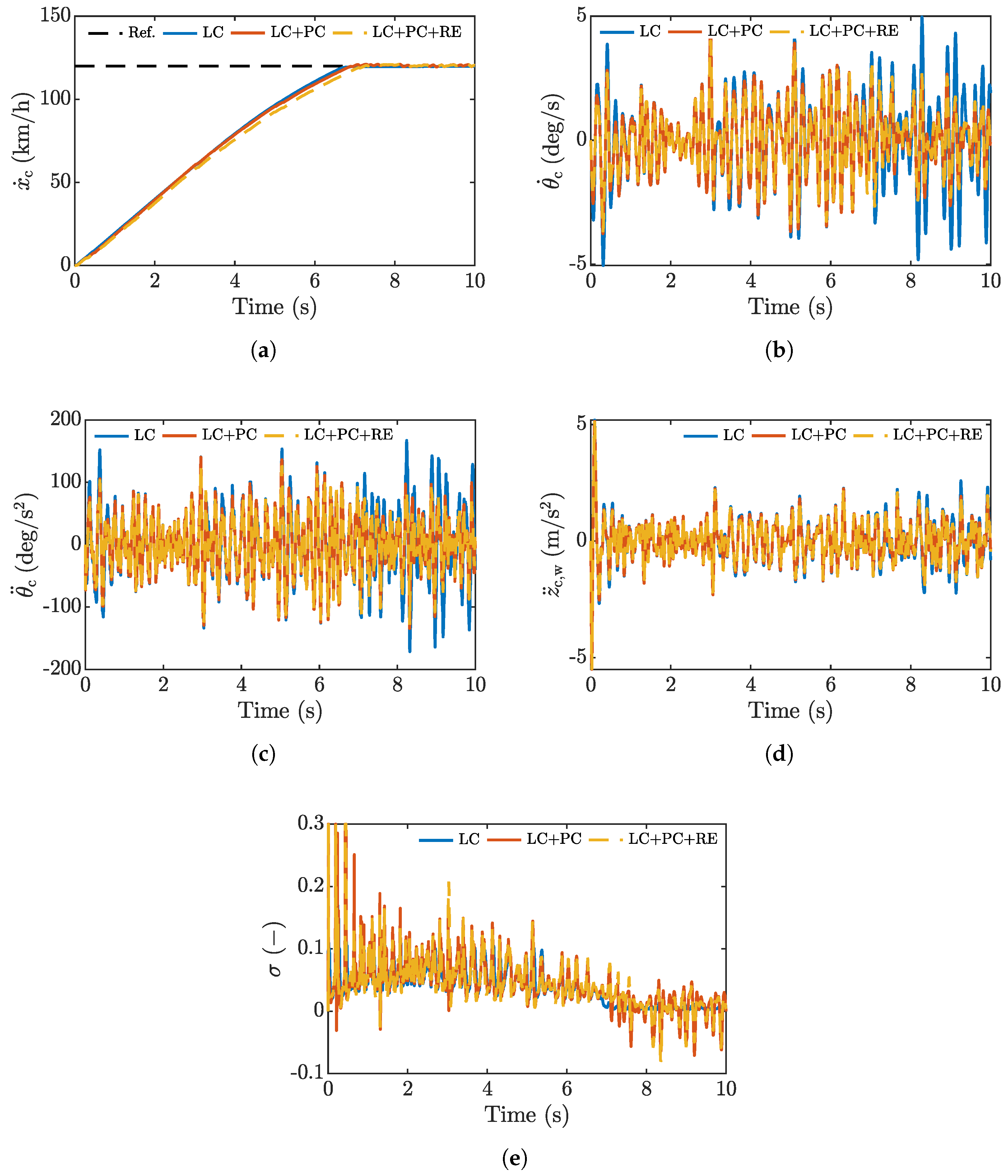
  • Highway test. Vehicle traveling through an ISO A road profile at 120 km / h .
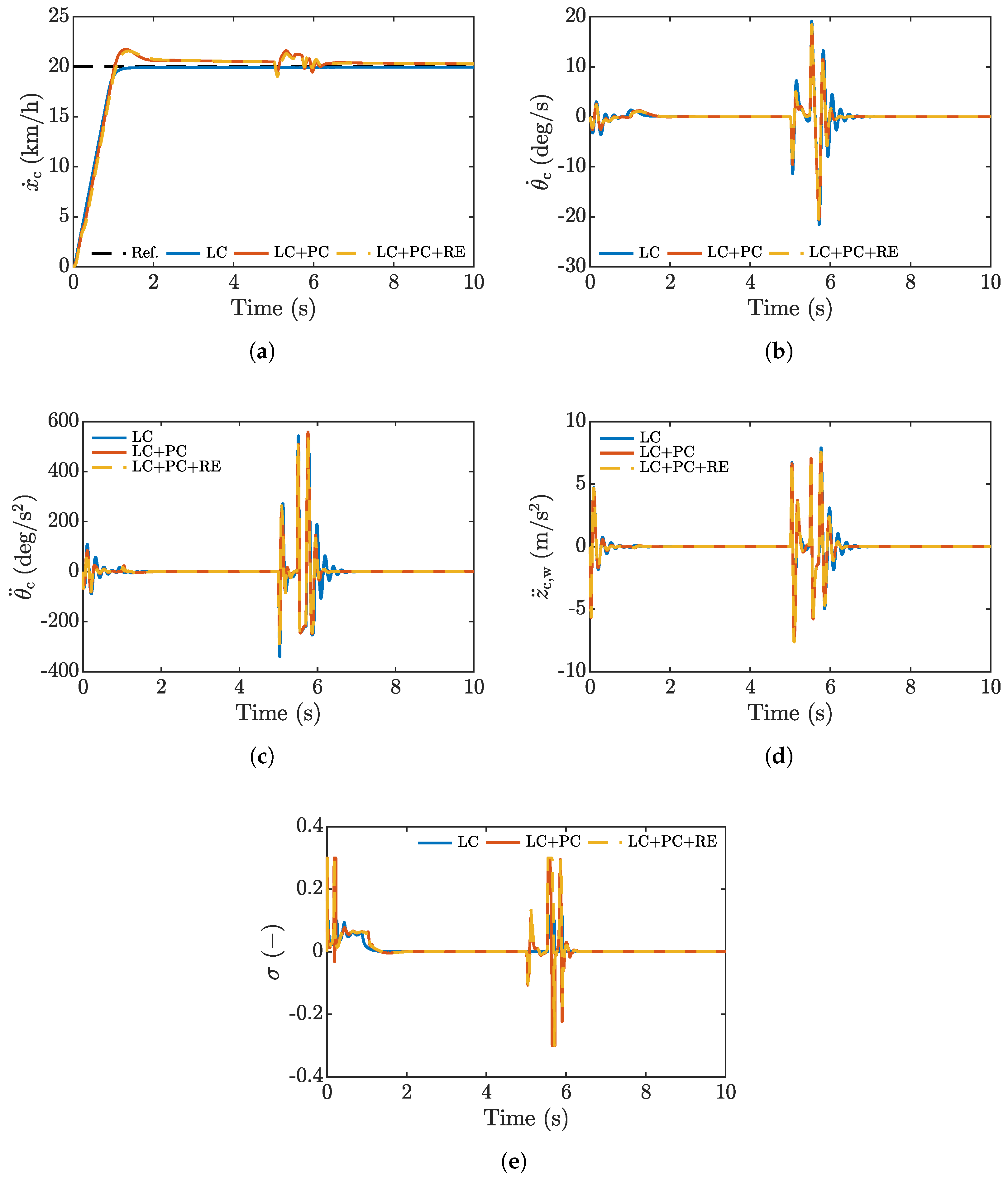
  • Bump test. Vehicle traveling through a speed bump obstacle at 20 km / h .
The following sections present and discuss the results obtained in these three representative tests.

4.1. Urban Test

A first test is performed under constant longitudinal speed of 35 km / h on an ISO B road. Figure 5 illustrates the vehicle performance under the three described control types: LC, LC+PC, and LC+PC+RE. Table 2 lists key performance metrics extracted from these time histories.
Figure 5a shows the tracking performance of the longitudinal control for the three outlined controllers. The addition of pitch attenuation slightly increase the settling time of traction control by 54 ms . This effect is worsened by adding the road profile estimator (LC+PC+RE), with a settling time increase of 116 ms with respect to LC. Such performance degradation is expected and can be attributed to the partial allocation of the IWM torque command for pitch rate attenuation, as well as the uncertainty related to road profile estimation. In average, the vehicle reaches the longitudinal speed setpoint of 35 km / h . However, the RMS values captured after the initial speed transient show that signals related to pitch rate attenuation (LC+PC and LC+PC+RE) present slight variability around the target speed.
Figure 5d shows the comfort performance related to the vertical acceleration of the chassis. The proposed Lyapunov-based control strategy addresses pitch dynamics exclusively. However, the intrinsic coupling between vertical and pitch degrees of freedom yield a consequent reduction of vertical acceleration. An attenuation of 6.93 % between LC and the pitch control variants is observed.
Similarly, Figure 5b presents the behavior of the chassis pitch rate for the three tested conditions. Enabling the Lyapunov controller provides favorable pitch rate attenuation (see Table 2). Pitch rate is reduced by 41.26 % when the road profile is estimated (LC+PC+RE). The pitch acceleration time history in Figure 5c can be related to passenger comfort as well. A beneficial attenuation of 36.51 % is observed for the LC+PC+RE configuration.
In terms of tire slip, Figure 5e shows that, besides the initial transient where the slip value reaches 0.3 , slip is well bound within acceptable RMS values below 0.05 . Enabling pitch attenuation control increases the slip activity of the tire. The effect is also explained by the RMS torque command effort in Table 2, which shows a clear increase of up to 40.88 % when the pitch rate attenuation control is enabled (LC+PC).
To validate the road profile estimation strategy, Figure 6a,b depict these displacements for the front and rear axles of the vehicle. The direct comparison between real ( w i ) and estimated ( w ^ i ) profiles is performed through the goodness of fit:
G F = 1 | | w i w ^ i | | | | w i w ¯ i | |
where w ¯ i denotes the average. The proposed estimator yields a goodness of fit G F = 0.929 for the front axle and G F = 0.908 for the rear axle.

4.2. Highway Test

In this test, the vehicle runs through a more regular ISO A profile, comparable to the quality of a highway, at 120 km / h . Resulting time histories are depicted in Figure 7, with RMS key performance indexes listed in Table 3.
From a qualitative perspective, the observed trends are very similar to those obtained on the urban test. This outcome is expected because Equation (20) shows that the road profile signal is proportional to G r x ˙ c . Shifting from B class to A class decreases the road roughness index G r by a ratio of 0.25 . By contrast, the speed is increased from 35 to 120 km / h i.e., by a factor of 3.42 . This leads to a reduction in the intensity of the road profile, with lower metrics overall, but very similar trends. The proposed Lyapunov-based control strategy can adapt to road profile and speed variations because it requires the knowledge of the vertical displacement of the road to produce a torque effort for pitch attenuation.

4.3. Bump Test

To validate the vehicle response in more demanding transient conditions, a bump profile was reproduced with a positive half of a sinusoidal waveform. This bump presents 40 mm of height and 400 mm width. The vehicle was set to overcome this obstacle at 20 km / h . Results for this test appear in Figure 8.
Figure 8a depicts the speed behavior of the vehicle. The LC control correctly follows the reference speed with a very slight disturbance at 5 s . LC+PC and LC+PC+RE strategies exhibit very similar behavior, as the road irregularity is very localized. A slight overshoot is present when the longitudinal speed control attempts to track the reference and when the vehicle hits the bump. As seen in the other tests, this is mainly due to the Lyapunov control, which affects the speed control by partially allocating the command effort during transients.
Figure 8b shows the behavior of the pitch rate. The LC+PC and LC+PC+RE control tests exhibit very similar behavior. At 2 s , when the vehicle reaches the reference speed, there is an increase in the pitch rate. Here, the LC control performs better than LC+PC and LC+PC+RE. When the vehicle hits the bump, the proposed LC+PC and LC+PC+RE strategies yield slightly lower peaks in pitch rate, pitch acceleration, and vertical acceleration (Figure 8b–d). The effects of the pitch attenuation strategies (LC+PC and LC+PC+RE) are advisable towards the end of the maneuver, where oscillations due to the rear wheel hop—very evident for the baseline LC control—are attenuated.

5. Conclusions

This paper proposed the integration of pitch rate attenuation control through an in-wheel motor actuation on the rear axle of an electric vehicle. The strategy consists of a longitudinal speed control that mimics the driver behavior and a nonlinear control system based on the synthesis of a Lyapunov function to mitigate the pitch rate on the vehicle body. This control is enabled by two Kalman filters acting as profile estimators that feed the instantaneous road unevenness to the pitch rate control.
For validation purposes, the proposed method was implemented on a half car model in MATLAB/Simulink. Tests in urban and highway scenarios demonstrated that the control strategy could reduce the pitch rate and pitch acceleration of the vehicle body by a significant margin (up to 41 % and 36 % , respectively), at the cost of slightly hindering the performance of the longitudinal control. Due to the actuation architecture, the vehicle showed a negligible improvement in vertical acceleration at the center of gravity of the vehicle body. Similar effectiveness was demonstrated through the bump obstacle test, where the proposed approach was able to mitigate oscillations due to wheel hop during a brief transient. Furthermore, the road profile estimators, which were based on a quarter car simplification of the model for each axle, reached a goodness of fit above 90 % when comparing their estimate to the real road profile.
The present proposal is limited to vehicles with in-wheel motors, where a sufficiently stiff traction deprived from backlash and other attenuation factors is possible. This constraint may hinder the applicability of the method to specific vehicles that can fit this technology. Moreover, the results discussed can change with external factors that modify the slip behavior of the tire, such as temperature, humidity and inflation pressure.
Future developments of this work will aim to implement this strategy on a real-time platform to run the control in parallel to a vehicle model based on a standardized vehicle simulator, such as CarSim. This tool would allow for the reproduction of full car dynamics. Furthermore, it would be suitable to test other strategies with pitch attenuation control for comparison purposes.

Author Contributions

Conceptualization, A.V.-S. and R.G.; methodology, A.V.-S., R.G., E.T., L.M.C.M. and R.C.; software, A.V.-S.; validation, A.V.-S., R.G., E.T. and R.C.; formal analysis, A.V.-S., R.G. and E.T.; investigation, A.V.-S.; resources, A.V.-S.; data curation, A.V.-S.; writing—original draft preparation, A.V.-S.; writing—review and editing, R.G., E.T., R.C. and L.M.C.M.; visualization, A.V.-S. and R.G.; supervision, R.G.; project administration, R.G. All authors have read and agreed to the published version of the manuscript.

Funding

Andrew Valdivieso-Soto is funded by Tecnologico de Monterrey, Grant No. A01658950, and Consejo Nacional de Humanidades, Ciencias y Tecnologias under the scholarship 1009565.

Institutional Review Board Statement

Not applicable.

Informed Consent Statement

Not applicable.

Data Availability Statement

The original contributions presented in the study are included in the article. Further inquiries can be directed to the corresponding author.

Conflicts of Interest

The authors declare no conflicts of interest.

List of Symbols

The following symbols are used in this manuscript. Subscript i = f, r denotes the axle, front or rear, respectively.
c x Longitudinal damping coefficient
c z i Suspension damping coefficient
d x i Changing longitudinal distance between wheel center and vehicle CoG
d z i Changing vertical distance between wheel center and vehicle CoG
f 0 Rolling resistance zero-degree polynomial coefficient
f 2 Rolling resistance second-degree polynomial coefficient
f 3 Road roughness cut-off frequency
f roll Rolling resistant coefficient function
gGravity acceleration
h cw Height from vehicle CoG to the wheel center
iAxle index (f–front,r–rear)
k t i Tire stiffness
k x Longitudinal stiffness coefficient
k z i Suspension spring stiffness
l i Semi-wheelbase distance
m c Sprung mass
m c i Corner sprung mass
m s Sprung mass
m i Unsprung mass
n ( t ) White noise signal
rPitch rate error
s i sign coefficient
t s Settling time
w i Road profile
w ^ i Estimated road profile
x c Longitudinal displacement of sprung mass
x i Longitudinal displacement of unsprung mass
x ˙ ref Sprung mass longitudinal velocity reference
y i Observation vector
z c Vertical displacement of the sprung mass CoG
z i Vertical displacement of the unsprung mass
z c i Corner vertical displacement
z ¨ c , w Weighted sprung mass vertical acceleration
A c Vehicle frontal area
A i Kalman filter state matrix
B tx Tire stiffness factor
C d Aerodynamic drag coefficient
C tx Tire shape factor
D tx Tire peak factor
E tx Tire curvature factor
F a Aerodynamic drag force
F cx i Longitudinal dissipative contribution suspension force
F kx i Longitudinal elastic contribution to the suspension force
F cz i Vertical shock absorber suspension force
F kz i Vertical spring suspension force
F roll , i Wheel rolling resistance force
F tx Tire longitudinal force
G F Goodness of fit
G r Road roughness index
H i Kalman filter observation matrix
IIdentity matrix
I z Pitch moment of inertia
K i Kalman gain matrix
Q i Model noise covariance matrix
R i Measurement noise covariance matrix
R lad , r Laden rear wheel radius
S vx Tire longitudinal force offset
T l Longitudinal torque command
T r Rear in-wheel motor torque
T ref Motor torque reference
T ref sat Saturated motor torque reference
T θ ˙ Pitch rate control command
VLyapunov function
α Road inclination angle
ε x ˙ Sprung mass longitudinal velocity error
κ Lyapunov control gain
ρ Air density
θ c Pitch angle at vehicle CoG
ξ i Kalman filter state vector
σ Tire slip ratio
τ Motor output filtering time constant
ω r Rear axle angular velocity
Acronyms
CoGCenter of gravity
IWMIn-wheel motor
ISOInternational Organization for Standardization
LCLongitudinal control
MPCModel predictive control
PCPitch control
PIProportional–integral control
RERoad profile estimator
RMSRoot mean square

References

  1. Deepak, K.; Frikha, M.A.; Benômar, Y.; El Baghdadi, M.; Hegazy, O. In-Wheel Motor Drive Systems for Electric Vehicles: State of the Art, Challenges, and Future Trends. Energies 2023, 16, 3121. [Google Scholar] [CrossRef]
  2. Szewczyk, P.; Łebkowski, A. Studies on Energy Consumption of Electric Light Commercial Vehicle Powered by In-Wheel Drive Modules. Energies 2021, 14, 7524. [Google Scholar] [CrossRef]
  3. Gobbi, M.; Sattar, A.; Palazzetti, R.; Mastinu, G. Traction motors for electric vehicles: Maximization of mechanical efficiency—A review. Appl. Energy 2024, 357, 122496. [Google Scholar] [CrossRef]
  4. Fujimoto, H.; Sato, S. Pitching control method based on quick torque response for electric vehicle. In Proceedings of the 2010 International Power Electronics Conference-ECCE ASIA, Sapporo, Japan, 21–24 June 2010; pp. 801–806. [Google Scholar]
  5. Kopylov, S.; Ambrož, M.; Petan, Ž.; Kunc, R.; Zheng, S.; Hou, Z. Vehicle pitch dynamics control using in-wheel motors. Proc. Inst. Mech. Eng. Part D J. Automob. Eng. 2024, 239, 1733–1744. [Google Scholar] [CrossRef]
  6. Ryu, K.; Kim, B.; Yoo, J.; Kim, J.; Bang, J.S.; Back, J. Robust Torque Vectoring with Desired Cornering Stiffness for In-Wheel Motor Vehicles. IEEE Access 2023, 11, 133021–133033. [Google Scholar] [CrossRef]
  7. Puma-Araujo, S.D.; Galluzzi, R.; Sánchez-Sánchez, X.; Ramirez-Mendoza, R.A. Study of Viscoelastic Rubber Mounts on Vehicle Suspensions with In-Wheel Electric Motors. Materials 2021, 14, 3356. [Google Scholar] [CrossRef]
  8. Zhiqiang, G.; Wei, W.; Shihua, Y. Longitudinal-vertical dynamics of wheeled vehicle under off-road conditions. Veh. Syst. Dyn. 2022, 60, 470–490. [Google Scholar] [CrossRef]
  9. Ma, Y.; Zhao, J.; Zhao, H.; Lu, C.; Chen, H. MPC-Based Slip Ratio Control for Electric Vehicle Considering Road Roughness. IEEE Access 2019, 7, 52405–52413. [Google Scholar] [CrossRef]
  10. Feng, J.; Liang, J.; Lu, Y.; Zhuang, W.; Pi, D.; Yin, G.; Xu, L.; Peng, P.; Zhou, C. An Integrated Control Framework for Torque Vectoring and Active Suspension System. Chin. J. Mech. Eng. 2024, 37, 10. [Google Scholar] [CrossRef]
  11. Li, Q.; Ma, C.; Zhang, N.; Guo, Y.; Degano, M.; Gerada, C.; Zhou, S.; An, Y. Analysis of longitudinal-vertical coupling vibration of four hub motors driven electric vehicle under unsteady condition. Proc. Inst. Mech. Eng. Part D J. Automob. Eng. 2024. [Google Scholar] [CrossRef]
  12. Xu, W.; Chen, H.; Zhao, H.; Ren, B. Torque optimization control for electric vehicles with four in-wheel motors equipped with regenerative braking system. Mechatronics 2019, 57, 95–108. [Google Scholar] [CrossRef]
  13. Vidal, V.; Stano, P.; Tavolo, G.; Dhaens, M.; Tavernini, D.; Gruber, P.; Sorniotti, A. On Pre-Emptive In-Wheel Motor Control for Reducing the Longitudinal Acceleration Oscillations Caused by Road Irregularities. IEEE Trans. Veh. Technol. 2022, 71, 9322–9337. [Google Scholar] [CrossRef]
  14. Wang, Q.; Zhao, Y.; Lin, F.; Zhang, C.; Deng, H. Integrated control for distributed in-wheel motor drive electric vehicle based on states estimation and nonlinear MPC. Proc. Inst. Mech. Eng. Part D J. Automob. Eng. 2022, 236, 893–906. [Google Scholar] [CrossRef]
  15. Kim, S.H.; Kim, K.K.K. Model Predictive Control for Energy-Efficient Yaw-Stabilizing Torque Vectoring in Electric Vehicles with Four In-Wheel Motors. IEEE Access 2023, 11, 37665–37680. [Google Scholar] [CrossRef]
  16. Castellanos Molina, L.M.; Manca, R.; Hegde, S.; Amati, N.; Tonoli, A. Predictive handling limits monitoring and agility improvement with torque vectoring on a rear in-wheel drive electric vehicle. Veh. Syst. Dyn. 2023, 62, 2185–2209. [Google Scholar] [CrossRef]
  17. Asperti, M.; Vignati, M.; Sabbioni, E. Torque Vectoring Control as an Energy-Efficient Alternative to Vehicle Suspensions Tuning. Energies 2024, 17, 2903. [Google Scholar] [CrossRef]
  18. Hou, R.; Zhai, L.; Sun, T.; Hou, Y.; Hu, G. Steering stability control of a four in-wheel motor drive electric vehicle on a road with varying adhesion coefficient. IEEE Access 2019, 7, 32617–32627. [Google Scholar] [CrossRef]
  19. Guo, L.; Ge, P.; Sun, D. Torque distribution algorithm for stability control of electric vehicle driven by four in-wheel motors under emergency conditions. IEEE Access 2019, 7, 104737–104748. [Google Scholar] [CrossRef]
  20. Chen, Y.; Chen, S.; Zhao, Y.; Gao, Z.; Li, C. Optimized handling stability control strategy for a four in-wheel motor independent-drive electric vehicle. IEEE Access 2019, 7, 17017–17032. [Google Scholar] [CrossRef]
  21. Xu, W.; Chen, H.; Wang, J.; Zhao, H. Velocity optimization for braking energy management of in-wheel motor electric vehicles. IEEE Access 2019, 7, 66410–66422. [Google Scholar] [CrossRef]
  22. Yim, S. Integrated chassis control with four-wheel independent steering under constraint on front slip angles. IEEE Access 2021, 9, 10338–10347. [Google Scholar] [CrossRef]
  23. Chae, M.; Hyun, Y.; Yi, K.; Nam, K. Dynamic handling characteristics control of an in-wheel-motor driven electric vehicle based on multiple sliding mode control approach. IEEE Access 2019, 7, 132448–132458. [Google Scholar] [CrossRef]
  24. Yu, Z.; Hou, Y.; Leng, B.; Xiong, L.; Li, Y. Disturbance compensation and torque coordinated control of four in-wheel motor independent-drive electric vehicles. IEEE Access 2020, 8, 119758–119767. [Google Scholar] [CrossRef]
  25. Jeong, Y.; Yim, S. Path tracking control with four-wheel independent steering, driving and braking systems for autonomous electric vehicles. IEEE Access 2022, 10, 74733–74746. [Google Scholar] [CrossRef]
  26. Lin, C.; Liang, S.; Chen, J.; Gao, X. A multi-objective optimal torque distribution strategy for four in-wheel-motor drive electric vehicles. IEEE Access 2019, 7, 64627–64640. [Google Scholar] [CrossRef]
  27. Tian, J.; Ding, J.; Zhang, C.; Luo, S. Four-wheel differential steering control of IWM driven evs. IEEE Access 2020, 8, 152963–152974. [Google Scholar] [CrossRef]
  28. Ricciardi, V.; Ivanov, V.; Dhaens, M.; Vandersmissen, B.; Geraerts, M.; Savitski, D.; Augsburg, K. Ride Blending Control for Electric Vehicles. World Electr. Veh. J. 2019, 10, 36. [Google Scholar] [CrossRef]
  29. Kanchwala, H.; Wideberg, J. Pitch reduction and traction enhancement of an EV by real-time brake biasing and in-wheel motor torque control. Int. J. Veh. Syst. Model. Test. 2016, 11, 165–192. [Google Scholar] [CrossRef]
  30. Yu, Y.; Xiong, L.; Yu, Z.; Yang, X.; Hou, Y.; Leng, B. Model-Based Pitch Control for Distributed Drive Electric Vehicle; Technical Report, SAE Technical Paper; SAE International: Warrendale, PA, USA, 2019. [Google Scholar]
  31. Bunlapyanan, C.; Chantranuwathana, S.; Phanomchoeng, G. Analytical Investigation of Vertical Force Control in In-Wheel Motors for Enhanced Ride Comfort. Appl. Sci. 2024, 14, 6582. [Google Scholar] [CrossRef]
  32. Kurz, C.; Stangenberg, L.; Gauterin, F. A Generic Approach to Modeling Vehicle Pitch Dynamics on a Vehicle Test Bench. IEEE Open J. Veh. Technol. 2023, 4, 739–748. [Google Scholar] [CrossRef]
  33. ISO 8608:2016; Mechanical Vibration–Road Surface Profiles–Reporting of Measured Data. International Organization for Standardization (ISO): Geneva, Switzerland, 2016.
  34. Luo, Y.; Tan, D. Study on the dynamics of the in-wheel motor system. IEEE Trans. Veh. Technol. 2012, 61, 3510–3518. [Google Scholar]
  35. Cespi, R.; Galluzzi, R. Model–Based Actuated Vertical Control of Ground Vehicles with Non-Negligible Roll Dynamics. In Proceedings of the 2022 International Symposium on Electromobility (ISEM), Puebla, Mexico, 17–19 October 2022; pp. 1–6. [Google Scholar]
  36. Doumiati, M.; Victorino, A.; Charara, A.; Lechner, D. Estimation of road profile for vehicle dynamics motion: Experimental validation. In Proceedings of the 2011 American Control Conference, San Francisco, CA, USA, 29 June–1 July 2011; pp. 5237–5242, ISSN 2378-5861. [Google Scholar] [CrossRef]
  37. Lewis, F.L.; Xie, L.; Popa, D. Optimal and Robust Estimation: With an Introduction to Stochastic Control Theory; CRC Press: Boca Raton, FL, USA, 2017. [Google Scholar]
  38. Pacejka, H. Tire and Vehicle Dynamics; Elsevier Ltd.: Amsterdam, The Netherlands, 2012. [Google Scholar] [CrossRef]
  39. ISO 2631:1997(E); Mechanical Vibration and Shock—Evaluation of Human Exposure to Whole-Body Vibration—Part 1: General Requirements. International Organization for Standardization (ISO): Geneva, Switzerland, 1997.
Figure 1. Half car model presenting the intrinsic coupling between vertical, pitch, and longitudinal dynamics.
Vehicles 07 00037 g001
Figure 2. In-wheel motor maximum torque-speed characteristic.
Vehicles 07 00037 g002
Figure 3. Block diagram of the Lyapunov-based pitch rate control strategy with road profile observer.
Vehicles 07 00037 g003
Figure 4. Longitudinal speed settling time ( t s , dotted red) and vehicle body RMS pitch rate ( rms ( θ ˙ c ) , dotted blue) for different pitch rate attenuation gains ( κ ). The vehicle follows a constant speed setpoint of 35 km / h through an ISO B road profile. The final selection κ = 155 is highlighted.
Vehicles 07 00037 g004
Figure 5. Vehicle response in a urban test (ISO B profile at 35 km / h ) for the three control configurations. (a) Longitudinal velocity of the vehicle. (b) Pitch rate, (c) pitch acceleration, and (d) weighted vertical acceleration at the vehicle CoG. (e) Rear tire slip ratio.
Vehicles 07 00037 g005
Figure 6. Road profile evolution considering a urban test (ISO B profile at 35 km / h ). Comparison between real (blue) and Kalman filter-estimated (dashed orange) profiles. (a) Front axle and (b) rear axle.
Vehicles 07 00037 g006
Figure 7. Vehicle response in a highway test (ISO A profile at 120 km / h ) for the three control configurations. (a) Longitudinal velocity of the vehicle. (b) Pitch rate, (c) pitch acceleration, and (d) weighted vertical acceleration at the vehicle CoG. (e) Rear tire slip ratio.
Vehicles 07 00037 g007
Figure 8. Vehicle response in a bump test for the three control configurations. (a) Longitudinal velocity of the vehicle. (b) Pitch rate, (c) pitch acceleration, and (d) weighted vertical acceleration at the vehicle CoG. (e) Rear tire slip ratio.
Vehicles 07 00037 g008
Table 1. D-class sport utility vehicle model parameters.
DescriptionSymbolValueUnits
Sprung mass m c 715 kg
Distance from vehicle CoG to wheel h cw 0.29 m
Front wheel distance to vehicle CoG l f 1.05 m
Rear wheel distance to vehicle CoG l r 1.61 m
Pitch inertia I z 1029.6 kgm 2
Longitudinal spring stiffness k x 170.1 N / mm
Longitudinal damping coefficient c x 3.3 Ns / mm
Front unsprung mass m f 71.35 kg
Front spring stiffness k zf 48.53 N / mm
Front damping coefficient c zf 6.28 Ns / mm
Rear unsprung mass m r 101.2 kg
Rear spring stiffness k zr 39.91 N / mm
Rear damping coefficient c zr 16.75 Ns / mm
Laden wheel radius R lad , r 0.347 m
Wheel spring stiffness k tf , k tr 338.055 N / mm
Torque control time constant τ 0.016 s
Mass density of the air ρ 1.225 kg / m 3
Frontal area of the vehicle A c 2.77 m 2
Drag coefficient C d 0.28
Gravitational acceleration g 9.81 m / s 2
Rolling resistance coeff. (zero degree) f 0 0.015
Rolling resistance coeff. (second degree) f 2 7 × 10 6 s 2 / m 2
Tire nominal stiffness factor B tx 20.74
Tire nominal shape factor C tx 1.26
Tire nominal peak factor D tx 8164 N
Tire nominal curvature factor E tx 1.09
Tire nominal longitudinal force offset S vx 0 N
Table 2. RMS key performance indexes for urban test. Percentages are calculated with respect to the baseline longitudinal control (LC).
Control Type x ˙ c
(km/h)
θ ˙ c
(deg/s)
θ ¨ c
(deg/s2)
z ¨ c , w
(m/s2)
T r
(Nm)
σ
(−)
LC 34.93 2.06 58.72 1.01 635.73 0.028
LC+PC 35.33
+1.15%
1.21
−41.26%
37.59
−36.95%
0.94
−6.93%
895.64
+40.88%
0.045
+60.7%
LC+PC+RE 35.33
+1.15%
1.21
−41.26%
37.28
−36.51%
0.94
−6.93%
830.18
+30.58%
0.040
+42.86%
Table 3. RMS key performance indexes for tests at road ISO A at 120 km/h constant speed. Percentages are calculated with respect to the baseline longitudinal control (LC).
Control Type x ˙ c
(km/h)
θ ˙ c
(deg/s)
θ ¨ c
(deg/s2)
z ¨ c , w
(m/s2)
T r
(Nm)
σ
(−)
LC 119.72 1.73 56.25 0.93 1184.3 0.054
LC+PC 120.30
+0.49%
1.37
−20.81%
46.88
−16.66%
0.87
−6.45%
1250.9
+5.62%
0.059
+9.26%
LC+PC+RE 120.36
+0.54%
1.30
−24.85%
44.70
−20.53%
0.86
−7.53%
1222.3
+3.20%
0.056
3.70%
Disclaimer/Publisher’s Note: The statements, opinions and data contained in all publications are solely those of the individual author(s) and contributor(s) and not of MDPI and/or the editor(s). MDPI and/or the editor(s) disclaim responsibility for any injury to people or property resulting from any ideas, methods, instructions or products referred to in the content.

