
Optimizing the Electrode Geometry of an In-Plane Unimorph Piezoelectric Microactuator for Maximum Deflection


Abstract
1. Introduction
2. Materials and Methods
3. Results and Discussion
4. Conclusions
Author Contributions
Funding
Data Availability Statement
Conflicts of Interest
Nomenclature
| Piezoelectric strain coefficients | |
| Strain | |
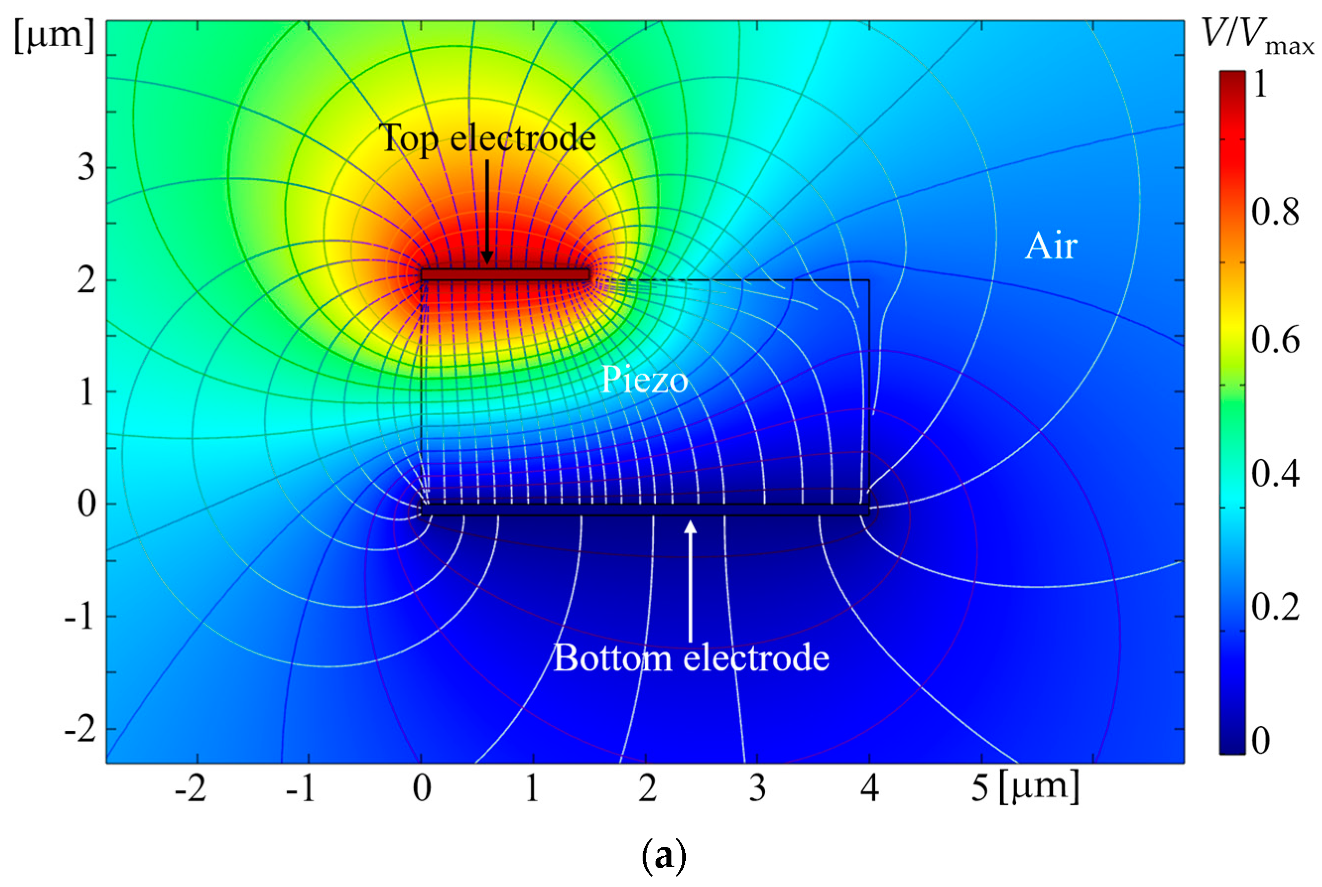
| Electric field | |
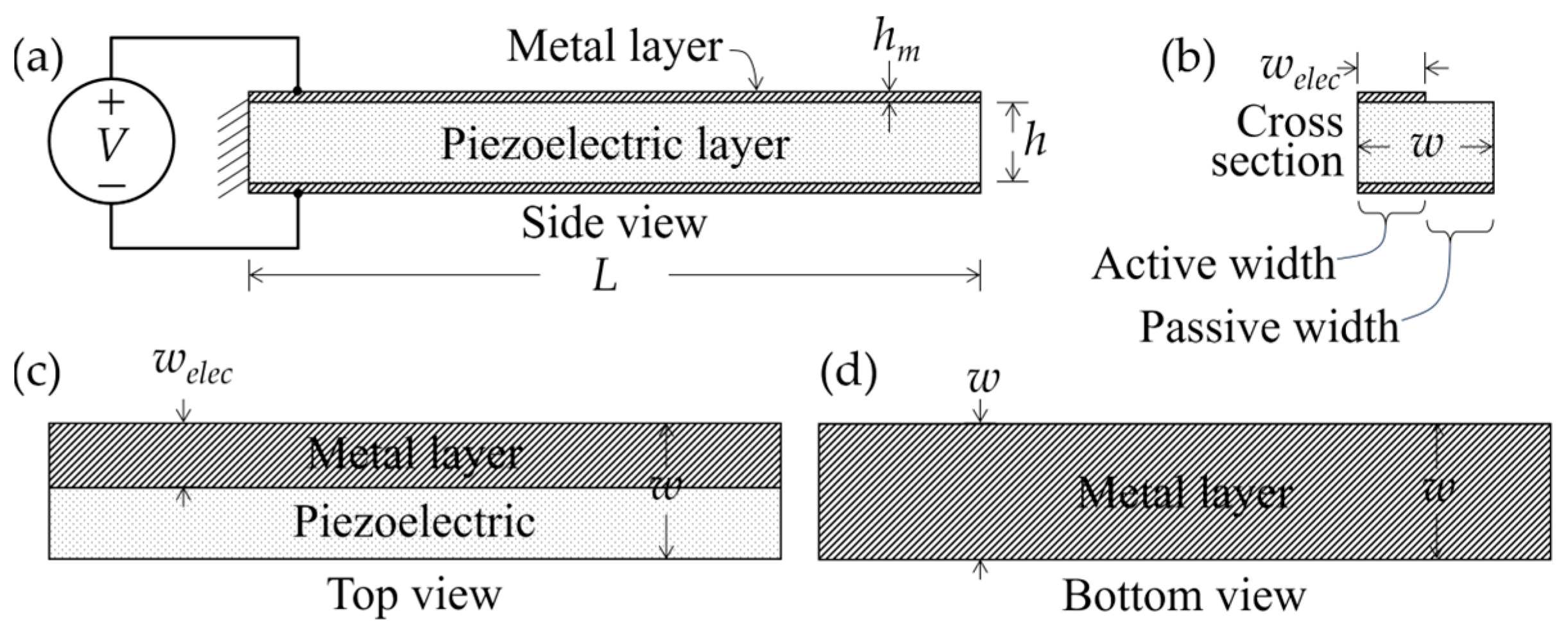
| Layer thickness of the unimorph | |
| Thickness of the top and bottom electrode layers | |
| Length of the unimorph | |
| Voltage | |
| Planar width of the unimorph | |
| Design constant chosen based on thickness | |
| Width of the top surface electrode | |
| Width of the passive surface, | |
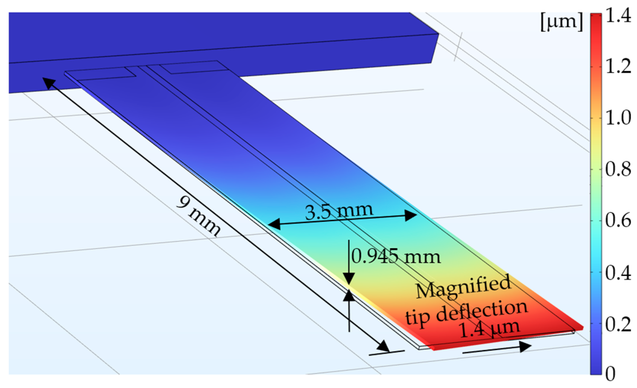
| Planar tip deflection of the unimorph |
References
- Fath, A.; Xia, T.; Li, W. Recent Advances in the Application of Piezoelectric Materials in Microrobotic Systems. Micromachines 2022, 13, 1422. [Google Scholar] [CrossRef] [PubMed]
- Ajitsaria, J.; Choe, S.Y.; Shen, D.; Kim, D.J. Modeling and analysis of a bimorph piezoelectric cantilever beam for voltage generation. Smart Mater. Struct. 2007, 16, 447–454. [Google Scholar] [CrossRef]
- Trolier-McKinstry, S.; Muralt, P. Thin Film Piezoelectrics for MEMS. J. Electroceramics 2004, 12, 7–17. Available online: https://link.springer.com/article/10.1023/B:JECR.0000033998.72845.51 (accessed on 17 August 2024). [CrossRef]
- Aabid, A.; Raheman, A.; Ibrahim, Y.E.; Anjum, A.; Hrairi, M.; Parveez, B.; Parveen, N.; Zayan, J.M. A Systematic Review of Piezoelectric Materials and Energy Harvesters for Industrial Applications. Sensors 2021, 21, 4145. [Google Scholar] [CrossRef] [PubMed]
- Liu, J.Q.; Xu, Z.Y. A Review of Piezoelectric Bimorph Power Generation. J. Nanotechnol. 2012, 12, 456–465. Available online: https://iopscience.iop.org/article/10.1088/1361-665X/ab36e4 (accessed on 17 August 2024).
- Stamatellou, A.-M. PZT and PVDF piezoelectric transducers’ design implications on their efficiency and energy harvesting potential. Energy Harvest. Syst. 2022, 10, 157–167. [Google Scholar] [CrossRef]
- Roundy, S.; Wright, P.K. A piezoelectric vibration based generator for wireless electronics. Smart Mater. Struct. 2004, 13, 1131–1142. Available online: https://iopscience.iop.org/article/10.1088/0964-1726/13/5/018 (accessed on 17 August 2024). [CrossRef]
- Shu, Y.C.; Lien, I.C. Analysis of power output for piezoelectric energy harvesting systems. Smart Mater. Struct. 2006, 15, 1499–1512. Available online: https://homepage.ntu.edu.tw/~yichung/power_harvesting_sms_2006.pdf (accessed on 17 August 2024). [CrossRef]
- Preumont, A. Vibration Control of Active Structures: An Introduction; Springer Science & Business Media: Berlin, Germany, 2011; Available online: https://link.springer.com/book/10.1007/978-94-007-2033-6 (accessed on 17 August 2024).
- DeVoe, D.; Pisano, A. Modeling and optimal design of piezoelectric cantilever microactuators. J. Microelectromech. Syst. 1997, 6, 266–270. [Google Scholar] [CrossRef]
- Guo, L.; Qin, Y. Modeling and analysis of a bimorph piezoelectric cantilever. In Proceedings of the 2016 13th International Conference on Ubiquitous Robots and Ambient Intelligence (URAI), Xi’an, China, 19–22 August 2016; pp. 248–251. [Google Scholar] [CrossRef]
- Ando, B.; Graziani, S.; Giannone, P. A Low Cost Experimental Set-up to Characterize Piezoelectric Cantilever Bimorphs. In Proceedings of the 2005 IEEE Instrumentationand Measurement Technology Conference Proceedings, Ottawa, ON, Canada, 16–19 May 2005; pp. 581–586. [Google Scholar] [CrossRef]
- Smits, J.; Ballato, A. Dynamic admittance matrix of piezoelectric cantilever bimorphs. J. Microelectromech. Syst. 1994, 3, 105–112. [Google Scholar] [CrossRef]
- Ali, A.; Pasha, R.A.; Elahi, H.; Sheeraz, M.A.; Bibi, S.; Hassan, Z.U.; Eugeni, M.; Gaudenzi, P. Investigation of Deformation in Bimorph Piezoelectric Actuator: Analytical, Numerical and Experimental Approach. Integr. Ferroelectr. 2019, 201, 94–109. [Google Scholar] [CrossRef]
- Huang, C.; Lin, Y.Y.; A Tang, T. Study on the tip-deflection of a piezoelectric bimorph cantilever in the static state. J. Micromech. Microeng. 2004, 14, 530–534. [Google Scholar] [CrossRef]
- Tadmor, E.; Kosa, G. Electromechanical coupling correction for piezoelectric layered beams. J. Microelectromech. Syst. 2003, 12, 899–906. [Google Scholar] [CrossRef]
- Yao, K.; Zhu, W.; Uchino, E.; Zhang, Z.; Lim, L.C. Design and fabrication of a high performance multilayer piezoelectric actuator with bending deformation. IEEE Trans. Ultrason. Ferroelectr. Freq. Control 1999, 46, 1020–1027. [Google Scholar] [CrossRef]
- Bergander, A.; Maeder, T.; Valencia, B.; Breguet, J.-M.; Ryser, P. Integrated sensors for PZT actuators based on thick-film resistors. In Proceedings of the 2002 International Symposium on Micromechatronics and Human Science, Nagoya, Japan, 23 October 2002; pp. 181–186. [Google Scholar] [CrossRef]
- Wang, Z.; Zhu, W.; Zhao, C.; Yao, X. Deflection characteristics of a trapezoidal multilayer in-plane bending piezoelectric actuator. IEEE Trans. Ultrason. Ferroelectr. Freq. Control 2001, 48, 1103–1110. [Google Scholar] [CrossRef]
- Díaz-Molina, A.; Hernando-García, J.; Sánchez-Rojas, J.L. Performance analysis of in-plane piezoelectric unimorph microactuators based on silicon and polymer substrates. J. Physics Conf. Ser. 2017, 922, 012021. [Google Scholar] [CrossRef]
- Toledo, J.; Ruiz-Díez, V.; Diaz-Molina, A.; Ruiz, D.; Donoso, A.; Bellido, J.C.; Wistrela, E.; Kucera, M.; Schmid, U.; Hernando-García, J.; et al. Design and characterization of in-plane piezoelectric microactuators. Actuators 2017, 6, 19. [Google Scholar] [CrossRef]
- Jones, N.A.; Clark, J. Analytical Modeling and Simulation of S-Drive Piezoelectric Actuators. Actuators 2021, 10, 87. [Google Scholar] [CrossRef]
- Younis, M.I. MEMS Linear and Nonlinear Statics and Dynamics; Springer: Berlin/Heidelberg, Germany, 2011; Available online: https://link.springer.com/book/10.1007/978-1-4419-6020-7 (accessed on 17 August 2024).
- Sol-Gel Solutions. Sol-Gel Solutions|Mitsubishi Materials Corporation Advanced Materials Div., Electronic Materials & Components Company. Available online: https://www.mmc.co.jp/adv/ele/en/products/assembly/solgel.html (accessed on 26 December 2023).
- Piezoelectric Sheets & Plates. PIEZO.COM. Available online: https://piezo.com/collections/piezo-sheets-plates?_=pf&pf_t_quantity=Quantity__1 (accessed on 26 December 2023).
- Build Your Own Custom Piezo. PIEZO.COM. Available online: https://piezo.com/pages/build-custom-piezo (accessed on 26 December 2023).
- Han, J.; Lang, J.H.; Bulovic, V. 8um Thick Piezo PVDF Film with 30 nm Thick Aluminum Electrode. Piezoelectric PVDF &PVDF-TrFE. Available online: https://piezopvdf.com/8-um-pvdf-film-aluminum-electrode/ (accessed on 17 August 2024).
- COMSOL MULTIPHYSICS® Software—Understand, Predict, and Optimize. COMSOL. Available online: https://www.comsol.com/comsol-multiphysics (accessed on 29 January 2024).
- Cheng, J.; Qian, C.; Zhao, M.; Lee, S.W.; Tong, P.; Zhang, T.-Y. Effects of electric fields on the bending behavior of PZT-5H pie-zoelectric laminates Smart Materials and Structures. Smart Mater. Struct. 2000, 9, 824–831. [Google Scholar] [CrossRef]
- Bruno, B.P.; Fahmy, A.R.; Stürmer, M.; Wallrabe, U.; Wapler, M.C. Properties of piezoceramic materials in high electric field actuator applications. Smart Mater. Struct. 2018, 28, 015029. [Google Scholar] [CrossRef]
- Tang, E.; Leng, B.; Han, Y.; Chen, C.; Chang, M.; Guo, K.; He, L. Influence of temperature on electromechanical responses of PZT-5H and output energy under shock loading. Mater. Chem. Phys. 2022, 276, 125309. [Google Scholar] [CrossRef]
- Wang, R.; Tang, E.; Yang, G.; Han, Y. Experimental research on dynamic response of PZT-5H under impact load. Ceram. Int. 2020, 46, 2868–2876. [Google Scholar] [CrossRef]
- Lu, X.M.; Proulx, T.L. Single crystals vs. pzt ceramics for medical ultrasound applications. In Proceedings of the IEEE Ultrasonics Symposium, Rotterdam, The Netherlands, 18–21 September 2005; pp. 227–230. [Google Scholar] [CrossRef]
- Systems, P. Material Properties. Piezo Support. Available online: https://support.piezo.com/article/62-material-properties (accessed on 5 May 2024).
- Vopsaroiu, M.; Weaver, P.M.; Cain, M.G.; Reece, M.J.; Chong, K.B. Polarization dynamics and non-equilibrium switching processes in ferroelectrics. IEEE Trans. Ultrason. Ferroelectr. Freq. Control 2011, 58, 1867–1873. [Google Scholar] [CrossRef] [PubMed]
- Michael, A.; Kwok, C. Piezoelectric micro-lens Actuator. Sensors Actuators A Phys. 2015, 236, 116–129. [Google Scholar] [CrossRef]
- Megginson, P.; Lowman, W.; Clark, J.; Clarson, R. Simulation Tools for Optimizing the Electrode Geometry of an In-Plane Unimorph Piezoelectric Microactuator. Available online: https://nanohub.org/resources/38096 (accessed on 17 August 2024).
- MATLAB. MathWorks. Available online: https://www.mathworks.com/products/matlab.html?s_tid=hp_products_matlab (accessed on 26 January 2024).
- GNU Octave. GNU Octave. Available online: https://octave.org/ (accessed on 18 January 2024).


Disclaimer/Publisher’s Note: The statements, opinions and data contained in all publications are solely those of the individual author(s) and contributor(s) and not of MDPI and/or the editor(s). MDPI and/or the editor(s) disclaim responsibility for any injury to people or property resulting from any ideas, methods, instructions or products referred to in the content. |
© 2024 by the authors. Licensee MDPI, Basel, Switzerland. This article is an open access article distributed under the terms and conditions of the Creative Commons Attribution (CC BY) license (https://creativecommons.org/licenses/by/4.0/).
Share and Cite
Megginson, P.; Clark, J.; Clarson, R. Optimizing the Electrode Geometry of an In-Plane Unimorph Piezoelectric Microactuator for Maximum Deflection. Modelling 2024, 5, 1084-1100. https://doi.org/10.3390/modelling5030056
Megginson P, Clark J, Clarson R. Optimizing the Electrode Geometry of an In-Plane Unimorph Piezoelectric Microactuator for Maximum Deflection. Modelling. 2024; 5(3):1084-1100. https://doi.org/10.3390/modelling5030056
Chicago/Turabian StyleMegginson, Parker, Jason Clark, and Ryan Clarson. 2024. "Optimizing the Electrode Geometry of an In-Plane Unimorph Piezoelectric Microactuator for Maximum Deflection" Modelling 5, no. 3: 1084-1100. https://doi.org/10.3390/modelling5030056
APA StyleMegginson, P., Clark, J., & Clarson, R. (2024). Optimizing the Electrode Geometry of an In-Plane Unimorph Piezoelectric Microactuator for Maximum Deflection. Modelling, 5(3), 1084-1100. https://doi.org/10.3390/modelling5030056