Abstract
The purpose of this work is a comparative analysis of the workpiece shape, and parameters of the stress-strain state during deformation on two radial-shear rolling mills with different roll configurations to determine the most suitable scheme for obtaining a screw reinforcement profile. During the FEM simulation of the radial-shear rolling process in the DEFORM program, a comparison of the workpiece shape change after rolling, equivalent strain, damage index, and Lode–Nadai index was carried out. Steel 10 (analogue of AISI 1010) was chosen as material workpiece. The analysis of the obtained data revealed that the most rational choice for the implementation of the reinforcement profile production process is the radial-shear rolling mill RSR 10-30. Subsequent modeling of the combined process of radial-shear rolling and twisting in a screw matrix showed that when using rolls of RSR 10-30 mill, the screw profile of the workpiece is formed successfully, whereas using rolls of the SVP-08 mill, the formation of a screw profile is impossible due to jamming due to an irregular cross-section shape. A laboratory experiment confirmed the possibility of forming a screw reinforcement profile at RSR 10-30 mill, and an assessment of the geometric parameters of the final workpiece showed full compliance with the dimensions of the profiles obtained during modeling and experiment.
1. Introduction
At the moment, almost 2 billion tons of steel are produced in the world, which is used for the manufacture of various metal products used in various industries. At the same time, it must be recognized that metallurgy is most often a “dirty” industry, since in this case there is quite a lot of environmental pollution. Therefore, metallurgical companies have been facing the task of “greening” metallurgy for more than a decade. And currently there are achievements in this direction. At the same time, I would like to note that the metal products themselves, which have served their service life, turn into waste, the so-called scrap, which also needs to be disposed of. One of the simplest and most frequently used methods of recycling ferrous scrap and alloys, as well as non-ferrous ones, is its remelting and further reuse. In some countries of the world, another method of its processing has long been put into practice, namely, the recycling of some metal products that have served their service life by various methods of hot pressure treatment to obtain a finished commercial product. In our opinion, this method of processing ferrous scrap and alloys can be attributed to “green” technologies, since it allows you to make a small contribution to improving the environmental situation in the world.
At the moment, in many countries of the world, a number of different technological processes have been developed for the processing of certain metal products that have served their service life by hot pressure treatment into a ready-made commercial product. The founder of this direction of processing metal products that have served their service life by hot pressure treatment is the American scientist E.E. Slick, who at the beginning of the last century developed a technology for processing railway rails by hot rolling in calibers in order to obtain flange profiles [1]. But then the technology he proposed was not widely used in practice. It was only at the end of the 20th century that the world scientific community and manufacturers of metal products became interested in this direction [2]. Some scientific groups describe the technologies for processing railway rails by hot rolling to produce various finished metal products [3,4]. For example, one of these technologies, namely, the technology of rolling railway rails into construction fittings, has found application at a metal rolling plant in Tula (Russia) [5].
Another promising way of recycling some metal products that have served their service life is their rolling on radial-shear rolling mills [6]. But most often this method is applicable only for recycling cylindrical metal products, for example, pumping rods [7] and used railway axles [8], as well as bar scrap of ferrous metals and alloys, including in the form of fittings [9]. In all cases, this method is based on the principle of hot radial-shear rolling of a used bar to a smaller diameter and subsequent use of the resulting bar of a smaller cross-section for its intended purpose. It should be noted that radial-shear rolling makes it possible to obtain long-length products from various materials with a gradient ultrafine-grained structure [10] and this method is the most technologically advanced and easy to implement compared with many other methods of metal forming, which realize severe plastic deformation [11]. There are many works devoted to the investigation of this process for the deformation of various materials. A special direction for this process is the investigation of aluminum alloys. During the last years, the results of radial-shear rolling of various steels, non-ferrous alloys, and composites were presented [12,13,14,15,16,17,18,19,20]. These works describe the influence of radial-shear rolling on the microstructure evolution and change in mechanical properties. Also, some works describe the radial-shear rolling of complex alloys. For example, in [21], the effect of the radial-shear rolling scheme on structure refinement and mechanical properties of the Al-Zn-Mg-Fe-Ni alloy was presented.
As already noted above, radial-shear rolling makes it possible to process bar scrap of ferrous metals to obtain a marketable product in the form of bars for various purposes. In the future, these rods can be used, among other things, to produce various high-quality metal products, for example, hardware products or a coupling screw for formwork, but this will require the use of additional technological solutions.
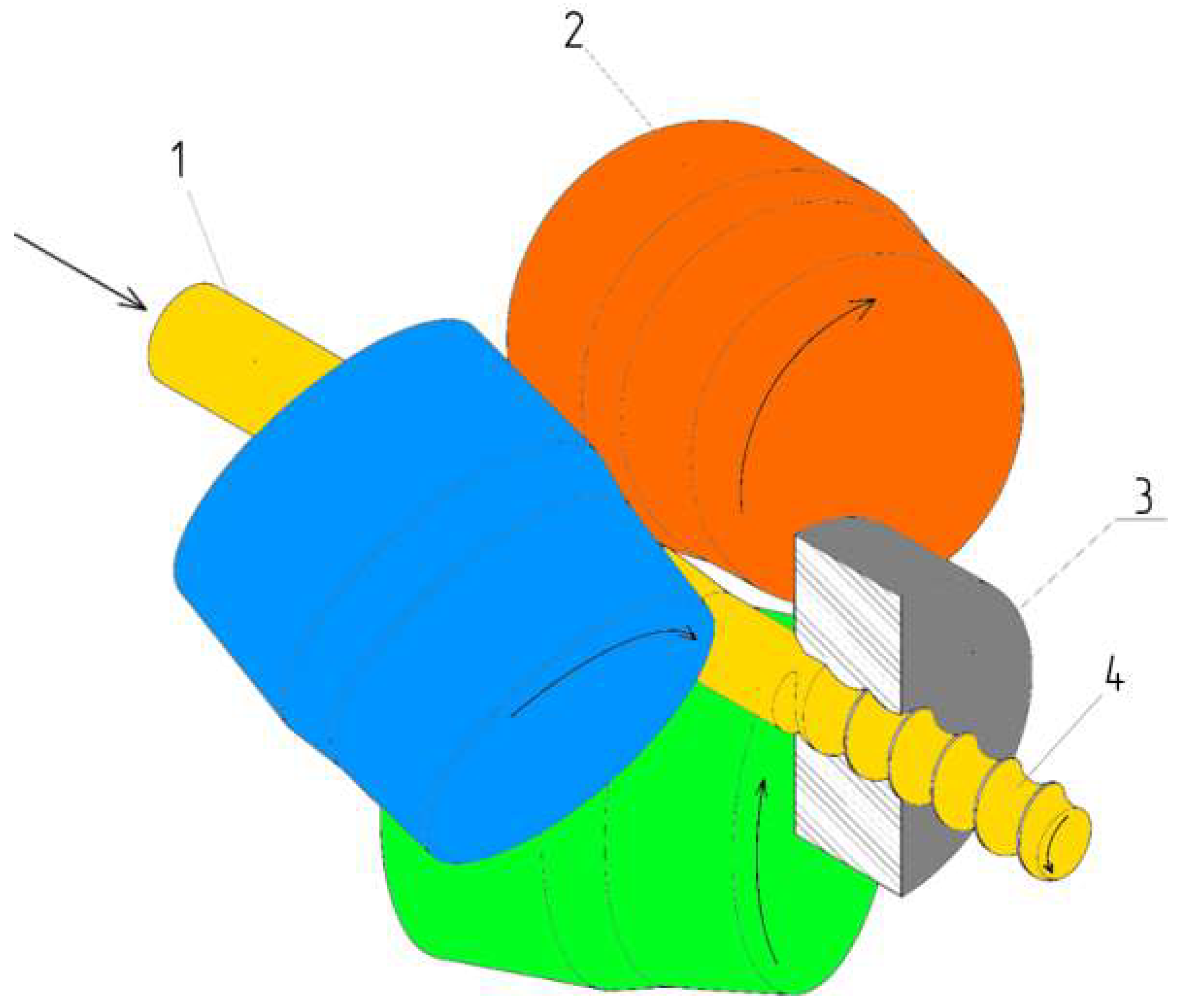
Developing the direction of recycling of bar scrap using radial-shear rolling, a technological process for processing bar scrap metal was proposed, combining radial-shear rolling and pressing through a screw matrix (Figure 1). This technology will make it possible to obtain a high-quality commercial product in the form of screw fittings with a gradient ultrafine-grained structure and with a given level of mechanical properties from bar scrap of circular cross-section, as well as fittings.

Figure 1.
Combined method for obtaining a reinforcing profile: 1—initial billet; 2—rolling rolls; 3—screw matrix; 4—screw profile.
This technology makes it possible to increase the manufacturability of the process of obtaining hardened screw fittings, since when it is implemented, when converting production to a standard size of screw fittings, only a new screw matrix of the desired diameter will need to be installed. In addition, due to the use of radial-shear rolling schemes in this scheme for obtaining screw fittings, it allows forming a gradient ultrafine-grained structure in the workpiece.
Earlier in [22], using computer modeling in the DEFORM software package (SFTC, Columbus, OH, USA) and the planning matrix, the possibility of implementing this combined process was proved and the most rational geometric and technological parameters for its implementation were determined. At the same time, the radial-shear rolling mill RSR 10-30 was used as rolling equipment. In ref. [23], the stress-strain state of this combined process at the RSR 10-30 mill was studied, proving the creation of favorable conditions for obtaining screw fittings with a gradient ultrafine-grained structure.
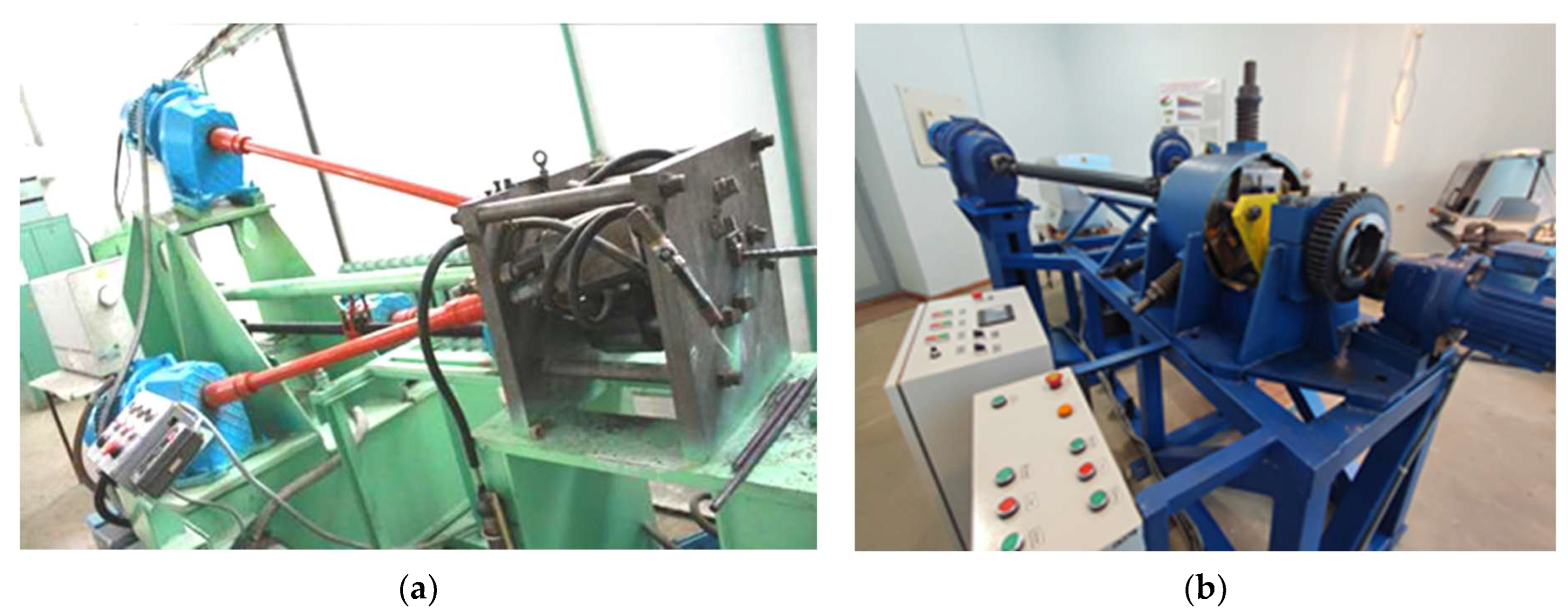
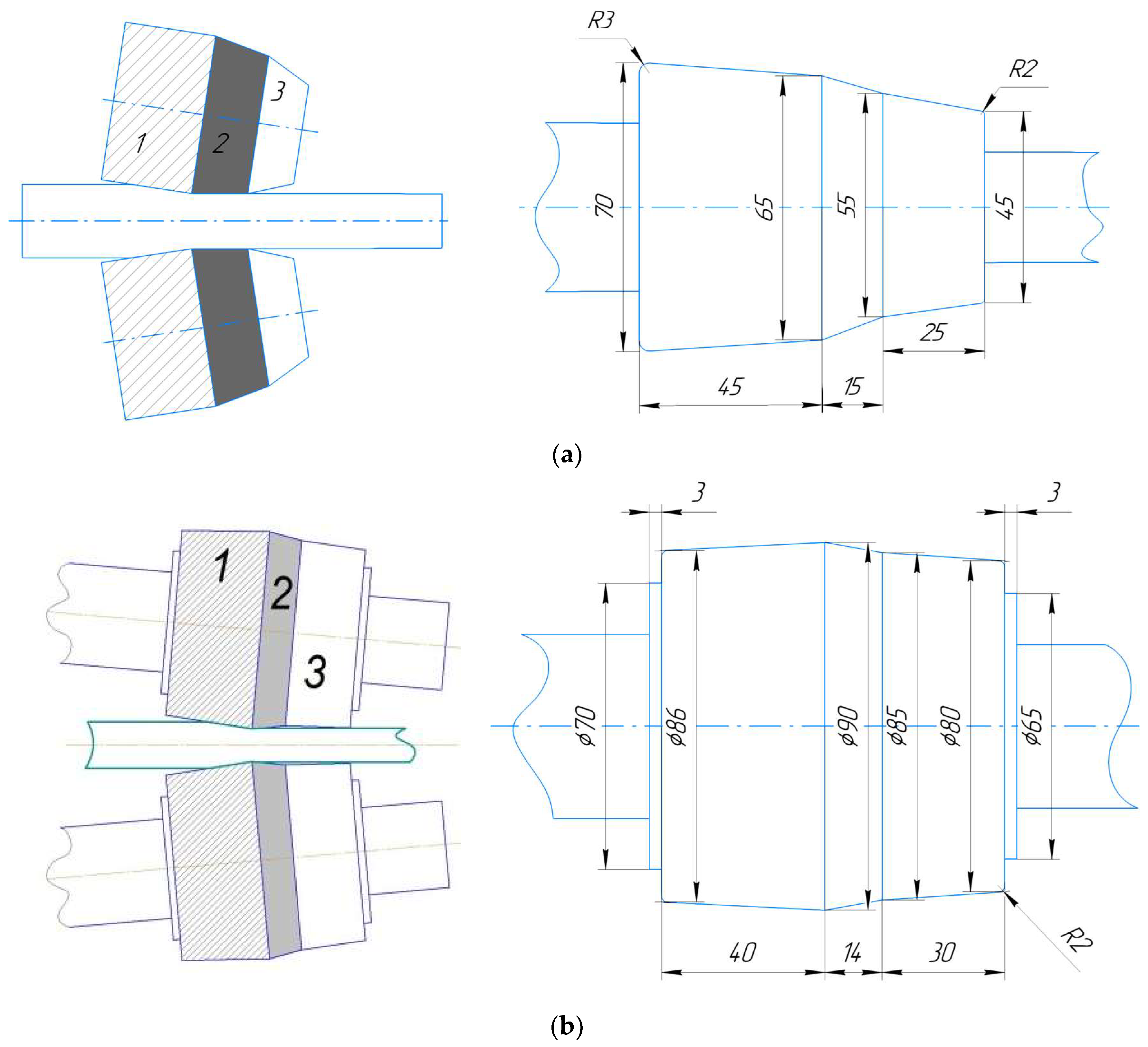
At the moment, to implement the proposed technology for obtaining hardened screw fittings by a continuous processing method combining in a single process: radial-shear rolling and shear deformation of twisting in a matrix, the authors of this work have two radial-shear rolling mills: RSR 10-30 mill (Figure 2a), installed at Karaganda Industrial University, and SVP-08 mill (Figure 2b), installed at Rudny Industrial University. Radial-shear rolling mills shown in Figure 2 have a different shape of rolls (Figure 3). At the same time, both rolling barrel designs consist of three sections—the input, Section 1, the calibration, Section 2, and the output, Section 3. The rolls of the RSR 10-30 mill (Figure 3a) allow only a direct deformation scheme, and rolls of the SVP-08 mill (Figure 3b) make it possible to realize the reversible nature of deformation. At the same time, one of the advantages of the SVP-08 mill is the extended range of the initial workpiece and the final profile. On the RSR 10-30 mill, it is possible to roll workpieces with a diameter from 30 mm to a final diameter of 10 mm. The SVP-08 mill can be used for rolling workpieces with a diameter from 40 mm to a final diameter of 8 mm. Taking into account the different shape of the rolls and the wider capabilities of this mill for the resulting assortment, it is necessary to study the possibility of implementing the combined process on it.

Figure 2.
Radial-shear rolling mills: (a) RSR 10-30 and (b) SVP-08.
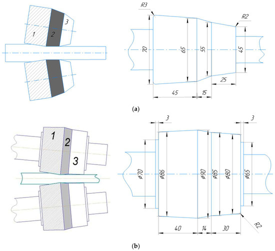
Figure 3.
Shape of rolls of radial-shear rolling mills: (a) RSR 10-30 and (b) SVP-08.
The main purpose of this study is to identify the most suitable configuration of rolls of a radial-shear rolling mill for obtaining screw fittings, as well as theoretical (FEM) and experimental confirmation of this choice. To achieve this purpose, it is necessary to solve the following objectives:
- -
- to conduct a comparative analysis of the workpiece shape, and the parameters of the stress-strain state of the workpiece during deformation on two radial-shear rolling mills with different roll configurations by FEM simulation;
- -
- to conduct a simulation of the combined deformation process, including the stages of radial-shear rolling and twisting in the matrix;
- -
- to conduct experimental verification of the simulation results by comparing the workpiece shape obtained during simulation and physical experiment.
2. Materials and Methods
As the main tool for comparative analysis, it was decided to use finite element modeling rather than physical experiment, since this method allows not only to study the shape change in metal during deformation and evaluate various parameters of the stress-strain state in a short time, but also to predict a stable deformation process or confirm its impossibility under specified conditions. At the same time, no significant costs are required. As an additional tool for comparative analysis, it was decided to conduct a physical experiment to verify the data obtained during the simulation. The key advantage of this methodology is that the identification of the most rational conditions for the implementation of the deformation process using finite element modeling can guarantee the successful implementation of this process in laboratory or industrial conditions.
The DEFORM program was used for FEM simulation of the radial-shear rolling process. The geometry of the rolls was taken from the characteristics of both mills. The initial diameter of the workpiece for simulation was 24 mm, the length of the workpiece was 150 mm, and rolling was carried out up to a diameter of 19 mm. A rolled rod with similar dimensions was used as the initial blank for the physical experiment without additional surface treatment in accordance with GOST 2590-2006 (without polishing or roughening the surface).
Steel 10 in accordance with GOST 1050-2013 (analogue of AISI 1010) was chosen as the material workpiece for simulation and experiment. The rheological properties of the workpiece material were taken from the internal materials database of DEFORM, which are presented for a temperature range of 800–1200 °C. The following technological parameters were used in computer simulation of the process:
- -
- workpiece material was isotropic and elastic-plastic; the material of rolls was rigid;
- -
- the type of finite elements is tetrahedral; the number of FE nodes is 76510, the number of FE is 352083. The finite element mesh had an adaptive type of remeshing, the key condition was to reduce the face of the finite element in the zones necessary for accurate rendering of the changing geometry. The advantage of the adaptive FE mesh is its independent “smart” distribution by volume of the workpiece at each calculation step. As a result, there is an intense condensation of elements in the necessary places. The coefficient of FE condensation in complex geometry zones is 4 (i.e., the volume of elements in the surface layer was 4 times less than in the rest of the workpiece);
- -
- rolling was carried out at an ambient temperature of 20 °C;
- -
- heating temperature of the workpiece before rolling was equal to 1100 °C;
- -
- the temperature of all deforming tools was equal to 20 °C;
- -
- the calculation type was non-isothermal; heat exchange coefficient of the workpiece with the tool was 5000 W/(m2·°C), as the recommended value by the DEFORM system;
- -
- heat exchange coefficient of the workpiece with the environment was 0.002 W/(m2·°C);
- -
- when calculating the contact interaction between the workpiece and the rolls, the Siebel friction was set; to create the most stringent conditions of capture, the friction coefficient on the contact of the metal with the rolls was adopted at 0.5 (which corresponds to a roughened surface with a high level of roughness in the complete absence of lubrication);
- -
- roll rotation speed was 50 rad/s;
- -
- in both models the feed angle was equal to 20°, the inclination angle was equal to 7°.
The calculation was carried out by a direct iterative method using a sparse matrix solver for a higher level of convergence at each step. In the calculation, a time increment was used to maintain high accuracy—1 step was equal to 0.001 s.
3. Results and Discussion
The main criteria for choosing the most optimal equipment for obtaining a reinforcing profile were the following indicators: workpiece shape change after rolling, equivalent strain, damage index, Lode–Nadai index.
Figure 4 and Figure 5 show the deformation zones during rolling on two radial-shear rolling mills and workpiece profiles at the exit of the rolls. At the RSR 10-30 mill, the deformation zone (Figure 4a) has an oblong and rather narrow zone, while at the SVP-08 mill (Figure 4b), the deformation zone has a characteristic S-shape, which is a key feature of step-shaped rolls that allow deforming workpieces in reverse mode.
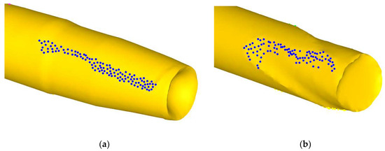
Figure 4.
Shape of deformation zone: (a) RSR 10-30 and (b) SVP-08.
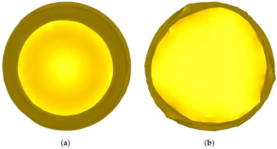
Figure 5.
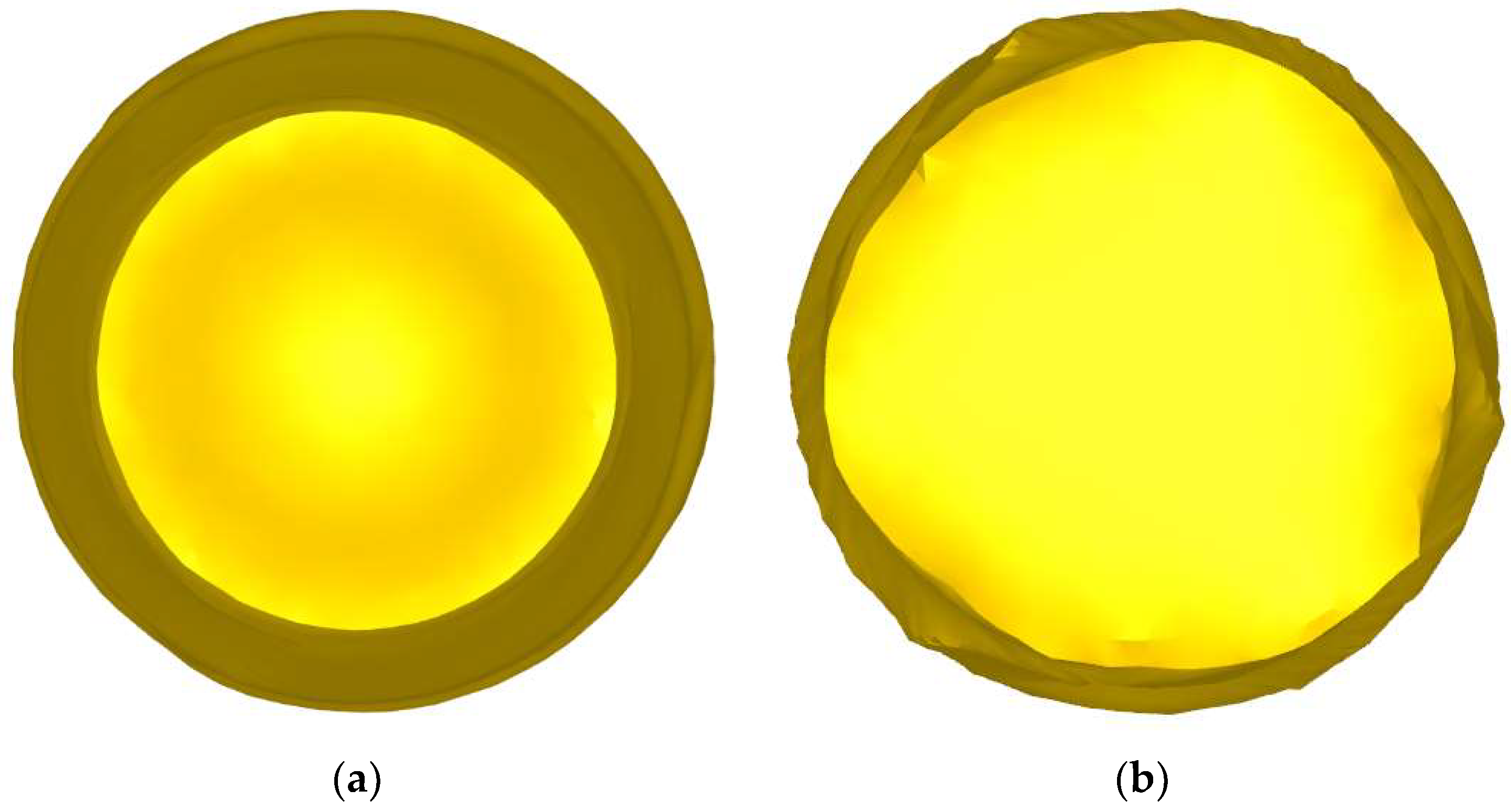
Workpiece profile at the exit of the rolls: (a) RSR 10-30 and (b) SVP-08.
In a comparative analysis of the shape change, it was decided that the optimal criterion is to obtain a cross-section close to the circle. When considering the workpiece profiles at the exit from the rolls, it can be seen that in the case of rolling on the RSR 10-30 mill (Figure 5a), the workpiece has a fairly correct circumference contour. After rolling on the SVP-08 mill (Figure 5b), the workpiece does not have such a smooth contour of the circle, spiral-shaped furrows from contact with the rolls are clearly visible on the surface of the workpiece. The formation of such a profile can lead to difficulty or impossibility of passing the workpiece in the matrix to obtain a reinforcement profile.
The calculation of equivalent strain is carried out according to the equation:
where ε1, ε2, ε3—principal strains.
In a comparative analysis of the equivalent strain, it was decided that the optimal criterion is to obtain more uniform round distribution and more deep processing in the cross-section. An analysis of the equivalent strain distribution (Figure 6) on both mills showed that the maximum values of strain in both cases are approximately the same, but there are significant differences in the distribution of strain over the surface and workpiece section. When rolling on the RSR 10-30 mill (Figure 6a), the workpiece undergoes a more significant processing both on the surface and in the peripheral zone.
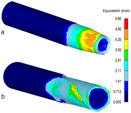
Figure 6.
Equivalent strain: (a) RSR 10-30 and (b) SVP-08.
The calculation of damage index is carried out according to the equation of the standard Cockcroft–Latham model:
where σ1—maximum principal stress; σEQV—effective stress; εEQV—value of equivalent strain.
The damage index makes it clear how much the workpiece is susceptible to destruction (the appearance of surface defects) during deformation by analyzing the level of tensile stresses. In a comparative analysis of the damage index, it was decided that the optimal criterion is to obtain the smallest values of this parameter. Figure 7 shows that when rolling at the RSR 10-30 mill (Figure 7a), this index does not exceed a critical value equal to 1, unlike rolling at the SVP-08 mill (Figure 7b), where the values of the damage index on the workpiece surface reach critical values, which negatively affects the surface quality of the workpiece and it can make further deformation in the screw matrix difficult. In real conditions, rolling on this mill is often accompanied by exfoliation of the surface layer, as shown in [24] (Figure 8).
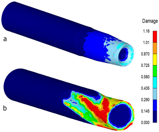
Figure 7.
Damage index: (a) RSR 10-30 and (b) SVP-08.
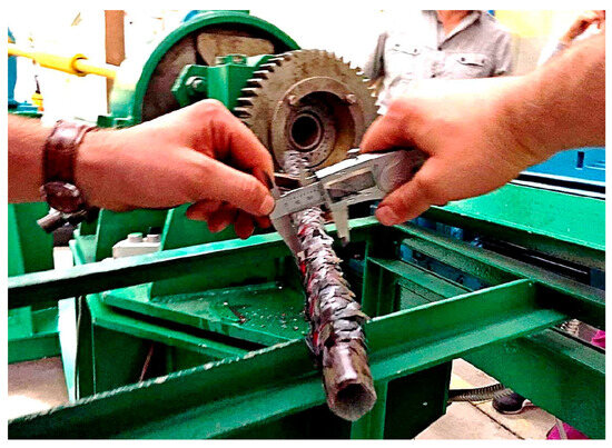
Figure 8.
Exfoliation of the surface layer during rolling on the SVP-08 mill.
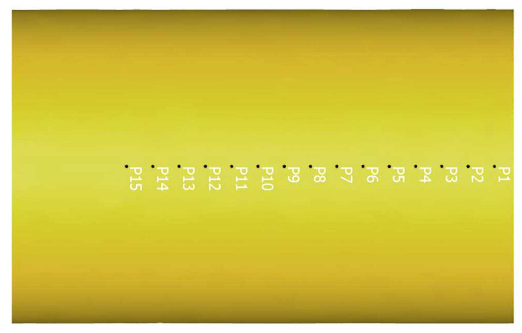
To determine the Lode–Nadai index after rolling in two mills, 15 monitored points were taken at the front end of the workpiece (Figure 9) on the surface and in the peripheral (0.5D) zones. This indicator allows to assess the nature of the deformation occurring in the workpiece, i.e., to determine which type of deformation is realized at a particular point—stretching, compression, or shear. The calculation of the Lode–Nadai index is carried out according to the formula:
where —principal stresses, MPa.
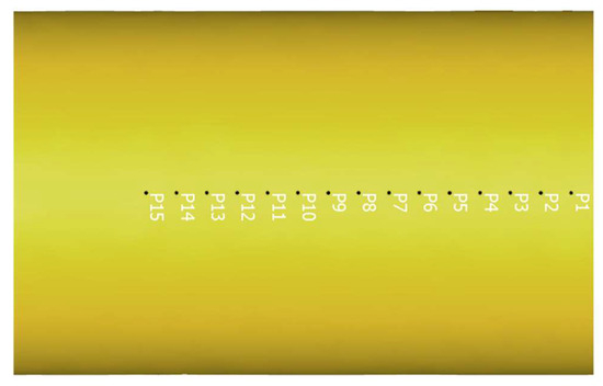
Figure 9.
Monitored points.
The value of the index varies from −1 to 1. A value from 0 to 1 corresponds to compression; from 0 to −1 corresponds to stretching; an index value tending to 0 corresponds to a shear. As shown in [25,26], the use of this criterion for the study of screw rolling and radial-shear rolling processes is the optimal choice.
In a comparative analysis of the Lode–Nadai index, it was decided that the optimal criterion is to obtain a distribution in which compressive stresses exceed tensile stresses. Figure 10 shows graphs of the Lode–Nadai index, from which it can be seen that when rolling the workpiece at the RSR 10-30 mill, the deformation pattern is distributed more evenly compared with rolling at the SVP-08 mill. The workpiece is mainly affected by either compressive or shear stresses and the level of tensile stresses developed at the outlet of the deformation zone is lower than compressive ones, which indicates a more favorable deformation pattern. In the case of rolling on the SVP-08 mill, the graphs of the Lode–Nadai index are heterogeneous in workpiece length. In the workpiece, due to the S-shaped contact with the rolls, the zones of tension, compression and shear alternate, and the extent of the zones of tensile stresses is greater here than in the first case.
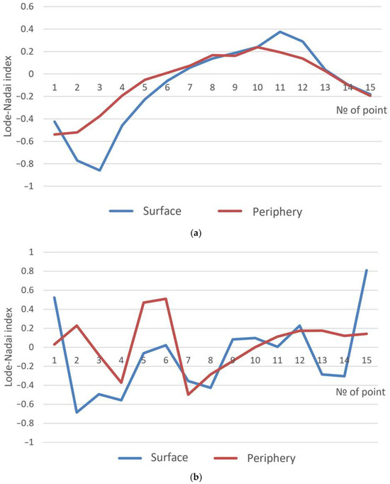
Figure 10.
Lode–Nadai index: (a) RSR 10-30 and (b) SVP-08.
The last stage of the simulation was the installation of a matrix at the exit of the rolls and the modeling of the formation of a screw reinforcement profile. When using the rolls of the RSR 10-30 mill, the screw profile of the workpiece was formed successfully (Figure 11), whereas using the rolls of the SVP-08 mill, the formation of the screw profile was stopped at the stage of entering the workpiece into the matrix (Figure 12) due to jamming due to an irregular section shape.
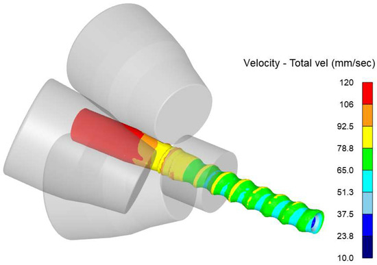
Figure 11.
Successful formation of a screw reinforcement profile at the RSR 10-30 mill.
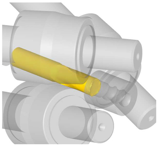
Figure 12.
Workpiece jamming on the SVP-08 mill.
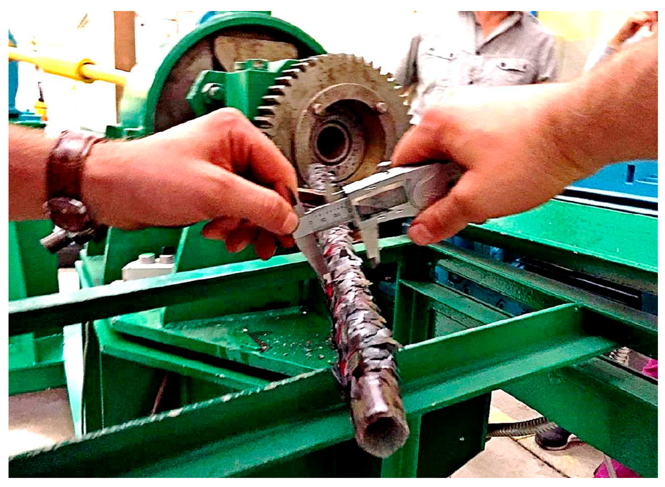
Based on the simulation results of radial-shear rolling on two mills, it was concluded that the most suitable and optimal choice for obtaining a reinforcing profile is the RSR 10-30 mill. The next stage of research was a laboratory experiment on the implementation of the technology being developed. The purpose of the experiment was to verify the data obtained during modeling on the possibility of forming a screw reinforcement profile at the RSR 10-30 mill, as well as to evaluate the geometric parameters of the final workpiece.
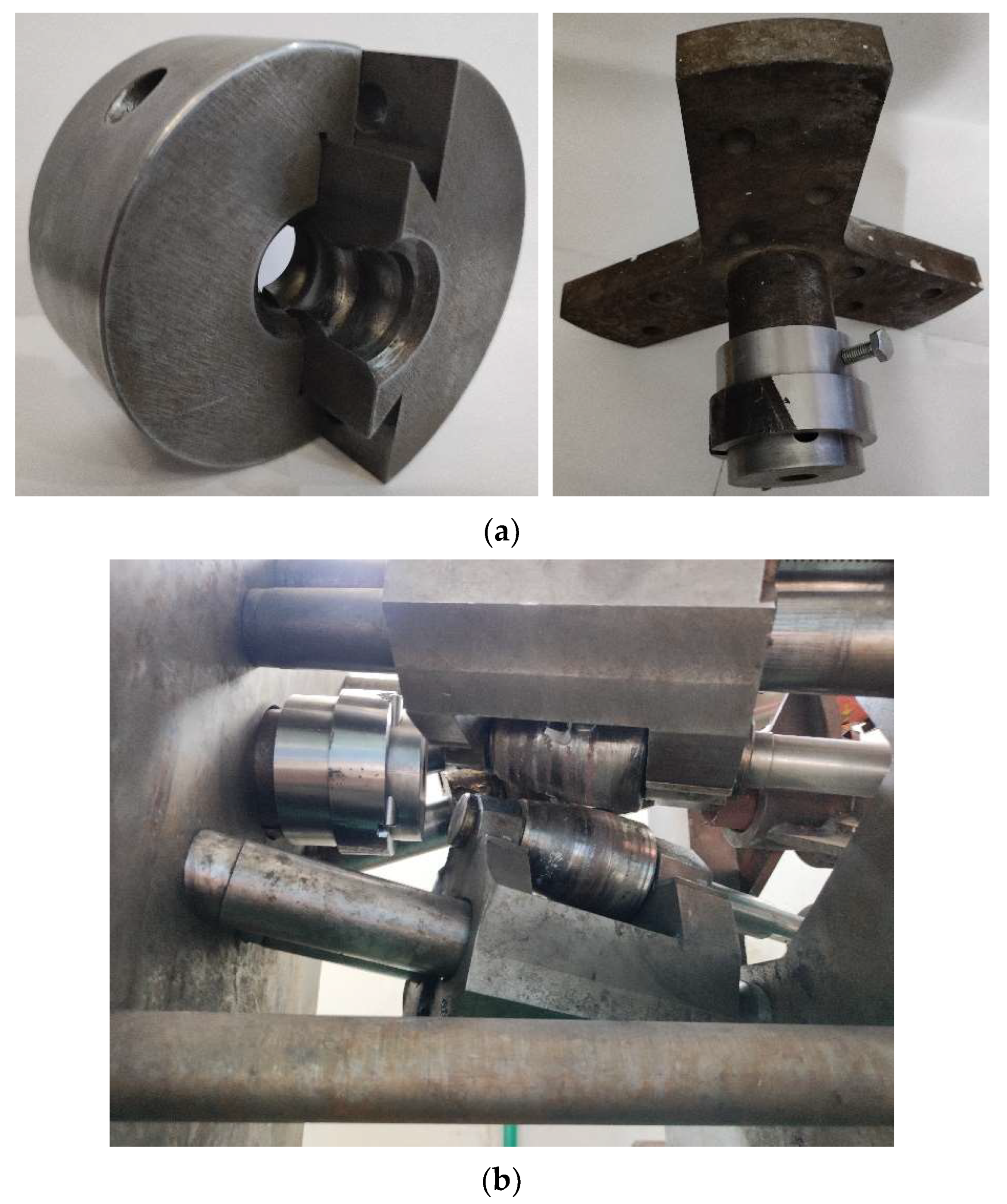
The screw die for pressing consisted of two segments connected according to the “dovetail” principle. The geometric dimensions of the matrix used in the simulation and experiment are shown in [23]. Figure 13a shows a general view of the matrix and its attachment in a special holder mounted on a three-beam rig. Figure 13b shows an experimental installation assembly.

Figure 13.
Experimental installation for forming a screw reinforcement profile: (a) General view of the matrix and its fastening in the cage and (b) general view of the deforming unit.
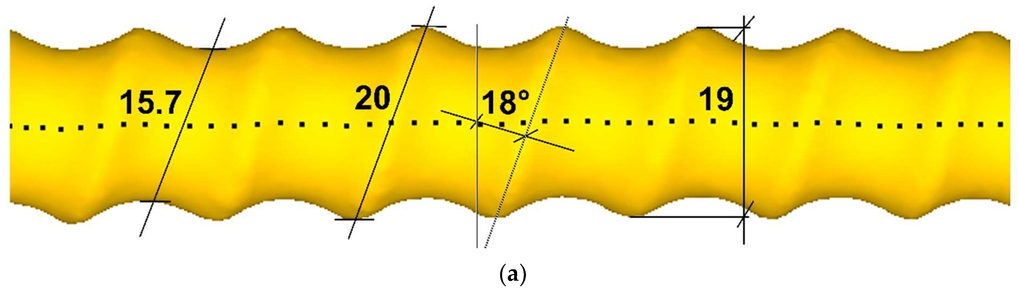
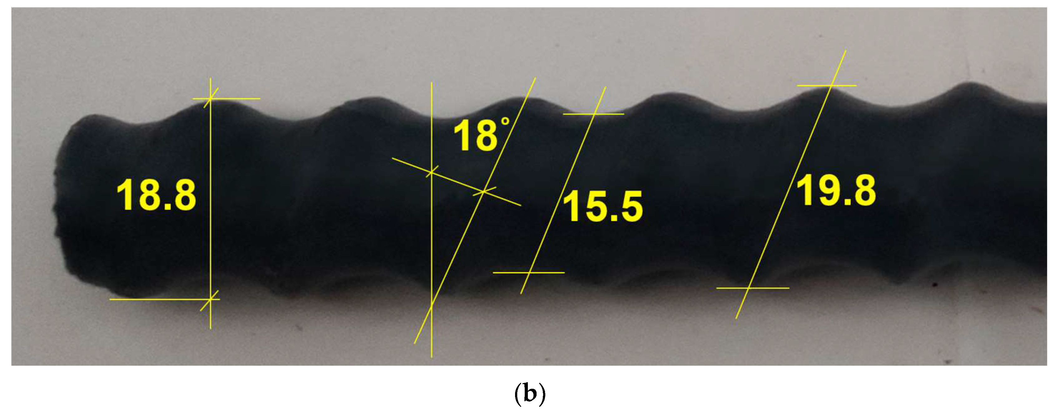
Since the main purpose of the experiment was to verify theoretical data, the experiment was carried out in strict accordance with all geometric and technological parameters established during modeling. Figure 14 shows the screw profiles of the workpieces obtained during modeling and after deformation in an experimental installation. The analysis of the main geometric elements of the profile revealed a complete correspondence between the dimensions of the profiles obtained during modeling and experiment.
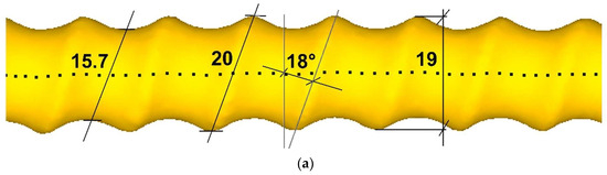
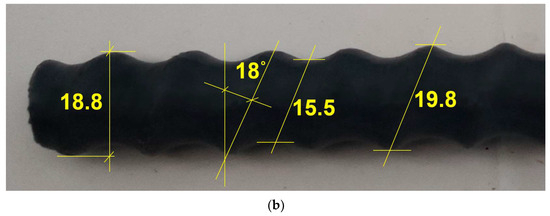
Figure 14.
Screw profile of the workpiece: (a) Modeling and (b) experiment.
4. Conclusions
A comparative analysis of the roll configurations installed on radial-shear rolling mills RSR 10-30 and SVP-08 on the workpiece shape, stress-strain state, and damage index using computer modeling in the DEFORM software showed that RSR 10-30 mill is the most suitable mill for implementing the proposed combined method for producing high-quality screw fittings, combining radial-shear rolling and twisting in a matrix. It is precisely during deformation at this radial-shear rolling mill that both obtaining a billet of the correct circular section and a higher level of metal processing without its destruction are ensured, compared with deformation at the SVP-08 mill.
Subsequent computer modeling of the combined process of obtaining screw fittings confirmed the results of an earlier comparative analysis. When using the rolls of the RSR 10-30 mill, the process proceeds stably, whereas when using the rolls of the SVP-08 mill, the process was interrupted due to jamming of the workpiece at the entrance to the matrix due to the irregular shape of the workpiece section.
The approbation of the proposed combined technology for producing screw fittings carried out during the physical experiment confirmed both the possibility of implementing the proposed combined process for producing screw fittings at the RSR 10-30 mill and the good convergence of the geometry of the resulting fittings during experiments with the results of computer modeling.
The proposed technology can be implemented at metallurgical and machine-building enterprises to produce high-quality screw fittings, including those with a gradient ultrafine-grained structure, which will be more metal products not for reinforced concrete reinforcement, but will be used as a threaded stud. This opens up a wider prospect for this type of metal product to be used in the same construction industry. For example, such a stud can be used together with nuts in concreting monolithic reinforced concrete structures for fastening formwork panels. At the same time, these threaded studs can be used once, i.e., remain in the reinforced concrete structure as an additional element of its reinforcement, or repeatedly, i.e., removed after stripping. In addition, such a screw stud can be used as foundation bolts used to attach various kinds of metal structures and technological equipment to reinforced concrete structures. And this is just a small example of the use of screw fittings in the construction industry.
When implementing this combined technology, rolled products of circular cross-section (GOST 2590-2006) and bar scrap of circular cross-section in the form of various metal products that have spent their service life can be used as the initial billet.
Author Contributions
Conceptualization, S.L. and A.N.; methodology, A.N. and A.A.; software, A.T. and E.P.; validation, A.N., E.P. and D.K.; formal analysis, A.A. and E.S.; investigation, D.K., P.T. and E.S.; resources, P.T.; data curation, E.P.; writing—original draft preparation, A.T.; writing—review and editing, E.P.; visualization, A.T. and A.A.; supervision, S.L.; project administration, S.L.; funding acquisition, S.L. All authors have read and agreed to the published version of the manuscript.
Funding
This research was funded by the Science Committee of the Ministry of Science and Higher Education of the Republic of Kazakhstan (grant number AP14869135).
Data Availability Statement
The DEFORM database used in this study is available from the corresponding author upon request.
Conflicts of Interest
Author Pavel Tsyba was employed by the company LLP Promtech Perspective. The remaining authors declare that the research was conducted in the absence of any commercial or financial relationships that could be construed as potential conflicts of interest.
Nomenclature
| Abbreviations | |
| FEM | finite element method |
| FE | finite elements |
| RSR | radial-shear rolling |
| SVP | “Stan Vintovoy Prokatki”—official Russian transliteration of radial-rhear rolling mill proposed by manufacturer |
| d | workpiece diameter (mm) |
| AISI | American Iron and Steel Institute—official name of standard for steels |
| Greek Symbols | |
| μ | Lode–Nadai index |
| σ | stress (MPa) |
| ε | strain |
References
- Slick, E.E. Method of Rolling Flanged Shapes. U.S. Patent 1086789, 10 February 1914. [Google Scholar]
- McGahhey, B.D. Rail Recycle Process. U.S. Patent 4982591, 08 January 1991. [Google Scholar]
- Smirnov, V.K.; Shilov, V.A.; Mikhailenko, A.M. Technology of processing railway rails for long products. Steel 1995, 2, 46–48. [Google Scholar]
- Bakhtinov, Y.B. On the expediency of rolling worn rails into long profiles. Prod. Roll. Prod. 2000, 7, 2–4. [Google Scholar]
- Badyuk, S.I.; Leshchenko, A.I. Obtaining long-range rolled profiles from worn-out railway rails. Process. Mater. Press. 2010, 4, 162–167. [Google Scholar]
- Galkin, S.P. Screw Rolling Method. RU Patent 2293619, 20 February 2007. [Google Scholar]
- Galkin, S.P.; Romantsev, B.A. Innovative technology of recycling pumping rods using technology and mini-installation of radial shear rolling in the conditions of JSC “Ochersky Machine-building Plant”. Eng. Pract. 2014, 9, 58–61. [Google Scholar]
- Grevtseva, V.V.; Galkin, S.P. Experimental testing of the technology of reuse of railway axles using radial shear rolling. In Proceedings of the 72nd Days of science of students of Nust Misis, Moscow, Russia, 16 March 2017; p. 297. Available online: https://misis.ru/files/-/a831b1fe883a9f5219573fbe2e64ceb8/72_DNI_all.pdf (accessed on 22 August 2024).
- Lezhnev, S.; Naizabekov, A.; Panin, E.; Volokitina, I.; Kuis, D. Recycling of stainless steel bar scrap by radial-shear rolling to obtain a gradient ultrafine-grained structure. Metalurgija 2021, 60, 339–342. [Google Scholar] [CrossRef]
- Galkin, S.P. Radial shear rolling as an optimal technology for lean production. Steel Transl. 2014, 44, 61–64. [Google Scholar] [CrossRef]
- Dobatkin, S.; Galkin, S.; Estrin, Y.; Serebryany, V.; Diez, M.; Martynenko, N.; Lukyanova, E.; Perezhogin, V. Grain refinement, texture, and mechanical properties of a magnesium alloy after radial-shear rolling. J. Alloys Compd. 2019, 774, 969–979. [Google Scholar] [CrossRef]
- Gamin, Y.V.; Akopyan, T.K.; Koshmin, A.N.; Dolbachev, A.P.; Goncharuk, A.V. Microstructure evolution and property analysis of commercial pure Al alloy processed by radial-shear rolling. Arch. Civ. Mech. Eng. 2020, 20, 143. [Google Scholar] [CrossRef]
- Stefanik, A.; Szota, P.; Mróz, S. Analysis of the Effect of Rolling Speed on the Capability to Produce Bimodal-Structure AZ31 Alloy Bars in the Three-High Skew Rolling Mill. Arch. Metall. Mater. 2020, 65, 329–335. [Google Scholar] [CrossRef]
- Mashekov, S.; Nurtazaev, E.; Mashekova, A.; Abishkenov, M. Extruding Aluminum Bars on a New Structure Radial Shear Mill. Metalurgija 2021, 60, 427–430. [Google Scholar]
- Mashekov, S.A.; Smailova, G.A.; Alshynova, A.M.; Uderbayeva, A.E.; Sembaev, N.S.; Zhauyt, A. Structure Formation of Aluminum Alloy D16 While Rolling Bars in the Radial Shear Mill. Metalurgija 2020, 59, 195–198. [Google Scholar]
- Petrova, A.N.; Rasposienko, D.Y.; Astafyev, V.V.; Yakovleva, A.O. Structure and strength of Al-Mn-Cu-Zr-Cr-Fe ALTEC alloy after radial-shear rolling. Lett. Mater. 2023, 13, 177–182. [Google Scholar] [CrossRef]
- Sheremetyev, V.; Kudryashova, A.; Cheverikin, V.; Korotitskiy, A.; Galkin, S.; Prokoshkin, S.; Brailovski, V. Hot radial shear rolling and rotary forging of metastable beta Ti-18Zr-14Nb (at.%) alloy for bone implants: Microstructure, texture and functional properties. J. Alloys Compd. 2019, 800, 320–326. [Google Scholar] [CrossRef]
- Kin, T.Y.; Gamin, Y.V.; Galkin, S.P.; Skugorev, A.V. Numerical simulation of workpiece temperature field during radial shear rolling of biomedical Co-Cr-Mo alloy. Model. Simul. Mater. Sci. Eng. 2023, 31, 065002. [Google Scholar] [CrossRef]
- Sheremet’ev, V.A.; Kudryashova, A.A.; Dinh, X.T.; Galkin, S.P.; Prokoshkin, S.D.; Brailovskii, V. Advanced technology for preparing bar from medical grade Ti-Zr-Nb superelastic alloy based on combination of radial-shear rolling and rotary forging. Metallurgist 2019, 63, 51–61. [Google Scholar] [CrossRef]
- Valeeva, A.H.; Valeev, I.S. The influence of radial shear rolling on the structure and properties of babbit B83. Mater. Sci. 2016, 2, 8–12. [Google Scholar]
- Brodova, I.; Rasposienko, D.; Shirinkina, I.; Petrova, A.; Akopyan, T.; Bobruk, E. Effect of Severe Plastic Deformation on Structure Refinement and Mechanical Properties of the Al-Zn-Mg-Fe-Ni Alloy. Metals 2021, 11, 296. [Google Scholar] [CrossRef]
- Lezhnev, S.; Panin, E.; Tolkushkin, A.; Kuis, D.; Kasperovich, A. Development and computer simulation of a new technology for forming and strengthening screw fittings. J. Chem. Technol. Metall. 2023, 58, 955–960. [Google Scholar] [CrossRef]
- Lezhnev, S.; Naizabekov, A.; Panin, E.; Tolkushkin, A.; Kuis, D.; Kasperovich, A.; Yordanova, R. Development and computer simulation of the new combined process for producing a rebar profile. Model. Simul. Eng. 2023, 2023, 7348592. [Google Scholar] [CrossRef]
- Arbuz, A.; Kawalek, A.; Ozhmegov, K.; Dyja, H.; Panin, E.; Lepsibayev, A.; Sultanbekov, S.; Shamenova, R. Using of Radial-Shear Rolling to Improve the Structure and Radiation Resistance of Zirconium-Based Alloys. Materials 2020, 13, 4306. [Google Scholar] [CrossRef]
- Pater, Z.; Tomczak, J.; Bulzak, T.; Wójcik, Ł.; Skripalenko, M.M. Prediction of ductile fracture in skew rolling processes. Int. J. Mach. Tools Manuf. 2021, 163, 103706. [Google Scholar] [CrossRef]
- Pater, Z. A comparison of two-roll and three-roll cross wedge rolling processes. Adv. Sci. Technol. Res. J. 2023, 17, 252–266. [Google Scholar] [CrossRef]


Disclaimer/Publisher’s Note: The statements, opinions and data contained in all publications are solely those of the individual author(s) and contributor(s) and not of MDPI and/or the editor(s). MDPI and/or the editor(s) disclaim responsibility for any injury to people or property resulting from any ideas, methods, instructions or products referred to in the content. |
© 2024 by the authors. Licensee MDPI, Basel, Switzerland. This article is an open access article distributed under the terms and conditions of the Creative Commons Attribution (CC BY) license (https://creativecommons.org/licenses/by/4.0/).