Abstract
Natural-fiber-reinforced composites are attracting an increasing amount of interest, and they are becoming more popular as a replacement for synthetic-fiber-reinforced composites. Natural-fiber-reinforced composites are important as a potential building material due to their lightweight nature, strength, and favorable qualities, which include eco-friendliness, non-toxicity, and biodegradability. Natural fibers such as hemp fibers, jute fibers, banana fibers, coconut fibers, sisal fibers, bamboo fibers, areca nut fibers, and kenaf fibers have been used for making composite panels because of their strength-to-weight ratio. Coconut inflorescence stem fibers are considered for our study. Coconut inflorescence stem-reinforced composite panels are often subjected to tensile load, compression load, and flexural load. Tensile strength, compressive strength, and flexural strength play a vital role when these panels are subjected to service loads. In this context, finite element analysis (FEA) is carried out on coconut inflorescence stem-reinforced panels subjected to tensile load, compressive load, and flexural load. A linear analysis is performed for the mechanical properties by using ANSYS workbench 2021 R1. A coconut inflorescence stem-reinforced composite specimen with the dimensions 280 mm × 25 mm × 3 mm (length × width × thickness) for tensile loading, 145 mm × 25 mm × 4 mm for the compressive load, and 150 mm × 25 mm × 4 mm for the flexural load is considered for the present study, as per the ASTM-D3039, ASTM-D3410, and ASTM-D790 standards, respectively. Finite element analysis results showed good correlation with the analytical results.
1. Introduction
Composite materials are used in engineering applications to reduce weight significantly, thereby reducing energy consumption and extending the life cycle of components and systems [1,2,3,4]. In recent years, weight-sensitive applications, such as aircraft, space vehicles, and in the construction industry, have become increasingly dependent on fiber-reinforced resin matrix composites [5,6,7]. The availability and ease of manufacture of polymer composites with natural fibers are attracting more interest in engineering applications. Eco-friendliness is also one of their best features, as they can be easily disposed of at the end of their life cycle. The following natural fibers are commonly used in composite manufacturing: jute, flax, banana, coir, sisal, kenaf, typha, luffa, and alpha [3]. Composite materials, especially those reinforced with natural fibers, can significantly reduce the weight of aircraft and spacecraft components [8,9,10]. Natural-fiber-reinforced composites could be used in structural elements, reducing the overall weight of buildings and potentially making construction processes more eco-friendly. These materials can help reduce the weight of vessels, contributing to better fuel efficiency and lower environmental impact. Natural fiber composites align with sustainability goals as they are biodegradable and can be disposed of more responsibly at the end of their life cycle. The development of new composite materials or the exploration of novel applications in industries like renewable energy or sports equipment manufacturing is of great importance. Existing studies predominantly concentrate on the mechanical properties of other natural fibers, such as jute, flax, banana, coir, sisal, kenaf, typha, luffa, and alpha [11,12,13,14,15]. There is a lack of comprehensive investigations into the tensile, compressive, and flexural behaviors of coconut inflorescence stem-fiber-reinforced composites. While experimental studies are available for certain aspects, there is a scarcity of numerical studies that simulate and analyze the mechanical behavior of these composites under various loads. Numerical simulations can provide valuable insights into the material’s performance and can guide the design process. The specimens were prepared for testing, in accordance with ASTM D-3410; ASTM D-790, and ASTM D-3039 [16]. For compressive strength, flexural strength, and tensile strength, specimen sizes are 145 mm × 25 mm × 4 mm, 150 mm × 25 mm × 4 mm, and 280 mm × 25 mm × 3 mm, respectively (length × width × thickness) [5,8]. By using finite element analysis (FEA) software, a 3D model of a specimen is disassembled into finite amounts of extremely small elements to solve engineering problems. In the literature, it has been observed that the FEA model results are quite similar to the experimental test results, which means that the fibers in actual composites are symmetrical and regular in their positioning. FEA models can effectively be used to study mechanical behavior [4].
2. Materials and Methods
Experiments were conducted on natural fiber composite panels to study the mechanical properties when subjected to compression load, flexural load, and tensile load. Coconut inflorescence stem fibers were used as a reinforcing material, and natural resins were used as the matrix, with cashew nutshell resin and epoxy used as a hardener. The mechanical properties of coconut inflorescence stem-fiber-reinforced composites are shown in Table 1 [1,2,6,10,14].

Table 1.
The mechanical properties of coconut inflorescence stem-fiber-reinforced composites.
2.1. Fiber Treatment Process
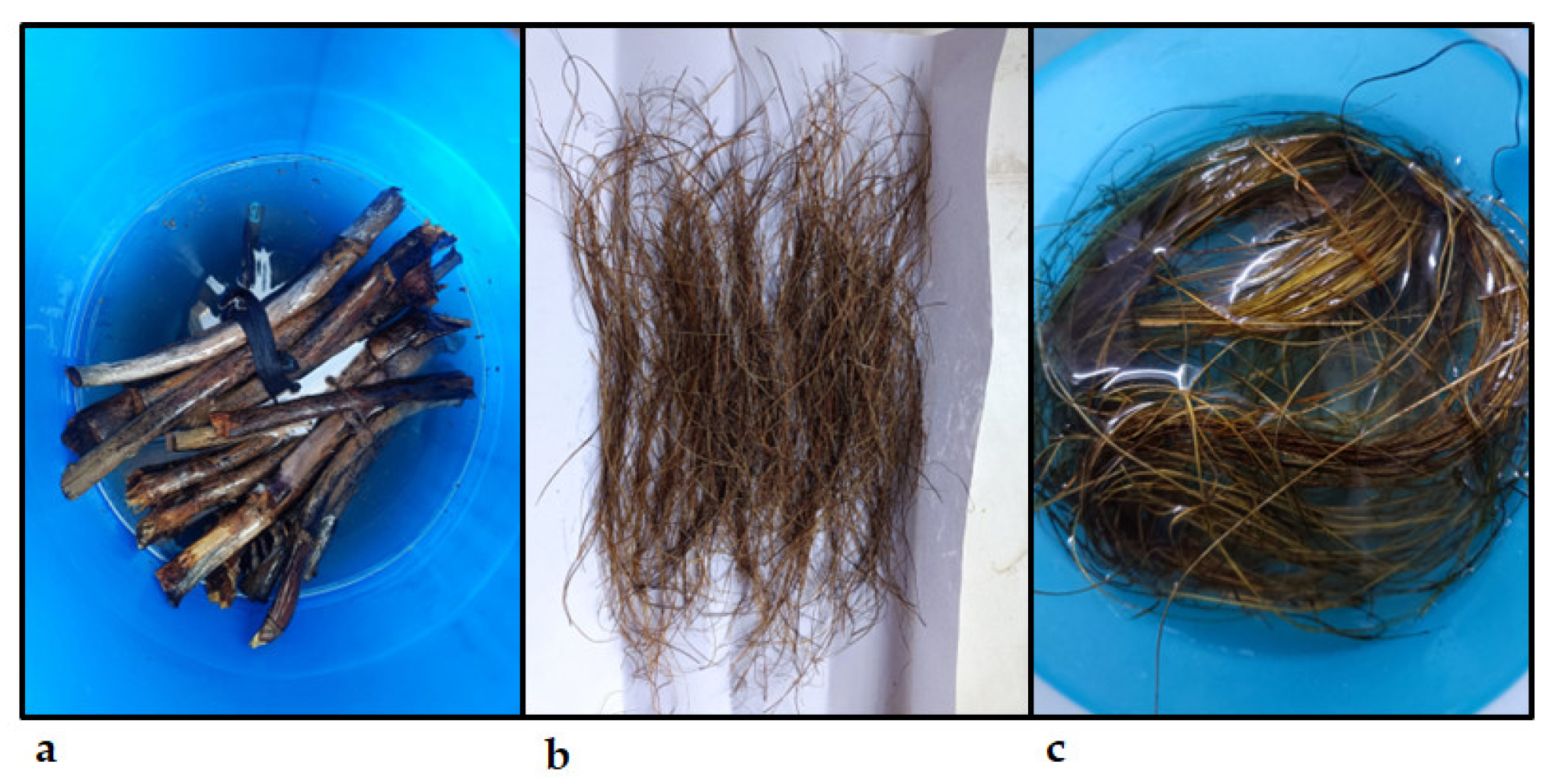
Coconut inflorescence stems were collected from plantations. These stems were cut into desired lengths and soaked in water for 30 days, which helps the extraction of fibers. The fibers extracted from the stem were treated with 5% NaOH and 95% water solution (50 g NaOH and 1 L water) and were allowed to soak in the solution for 24 h to remove unwanted impurities, as shown in Figure 1. After 24 h, the fibers were taken out of the solution and rinsed two to three times with distilled water to eliminate any residue of NaOH. These fibers were then exposed to the sun for 24 h to dry.

Figure 1.
(a) Coconut inflorescence stem subjected to water treatment; (b) extracted untreated fibers; (c) 5% NaOH-treated fibers.
2.2. Experimental Setup
Experiments were carried out for coconut inflorescence stem-fiber-reinforced composite specimens, which are made using 5 mm, 10 mm, and 15 mm fiber lengths. These specimens are subjected to compression, flexure, and tension with the aid of a universal testing machine with a capacity of 10 kN. The upper end and lower end of the specimens were gripped using automated grippers with a gripping pressure of 3 MPa. Compression, flexure, and tensile tests were carried out at a room temperature of 30 °C and at a loading rate of 0.5 mm per minute. The experimental setup is as shown in Figure 2.
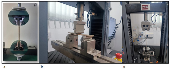
Figure 2.
(a) Compression test, (b) flexural test, and (c) tensile test setup for coconut inflorescence stem-fiber-reinforced composite specimens.
3. Finite Element Modeling
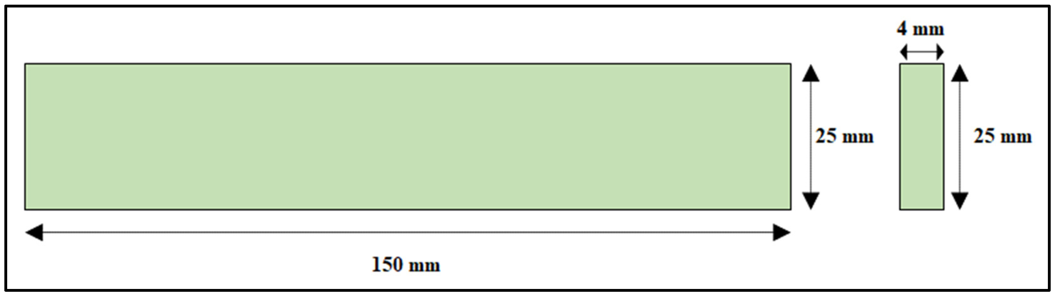
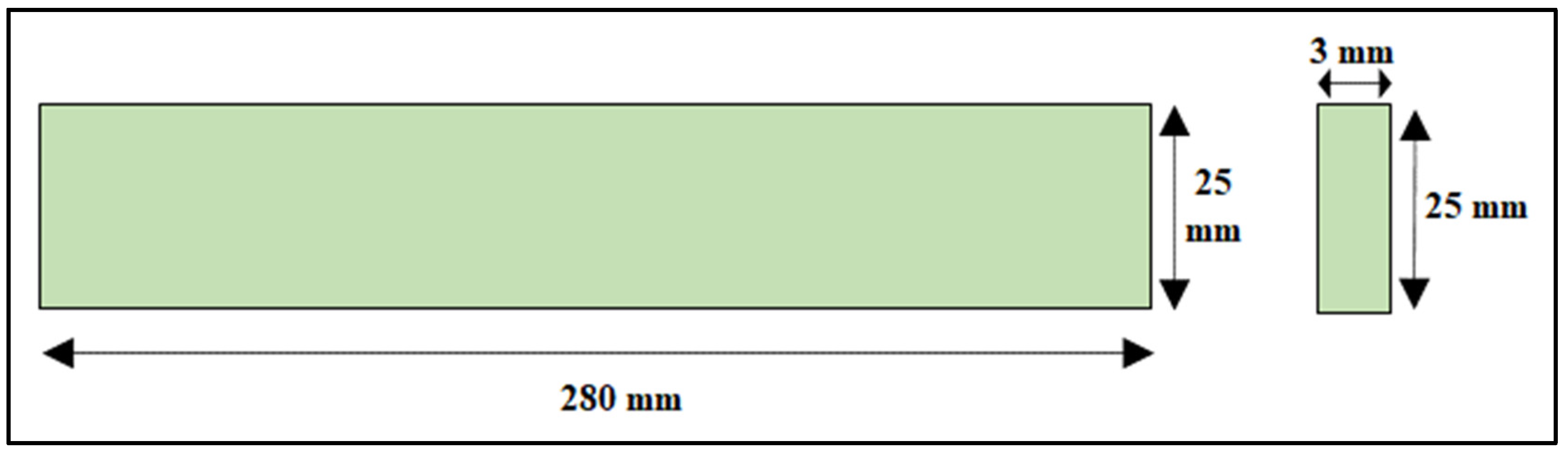
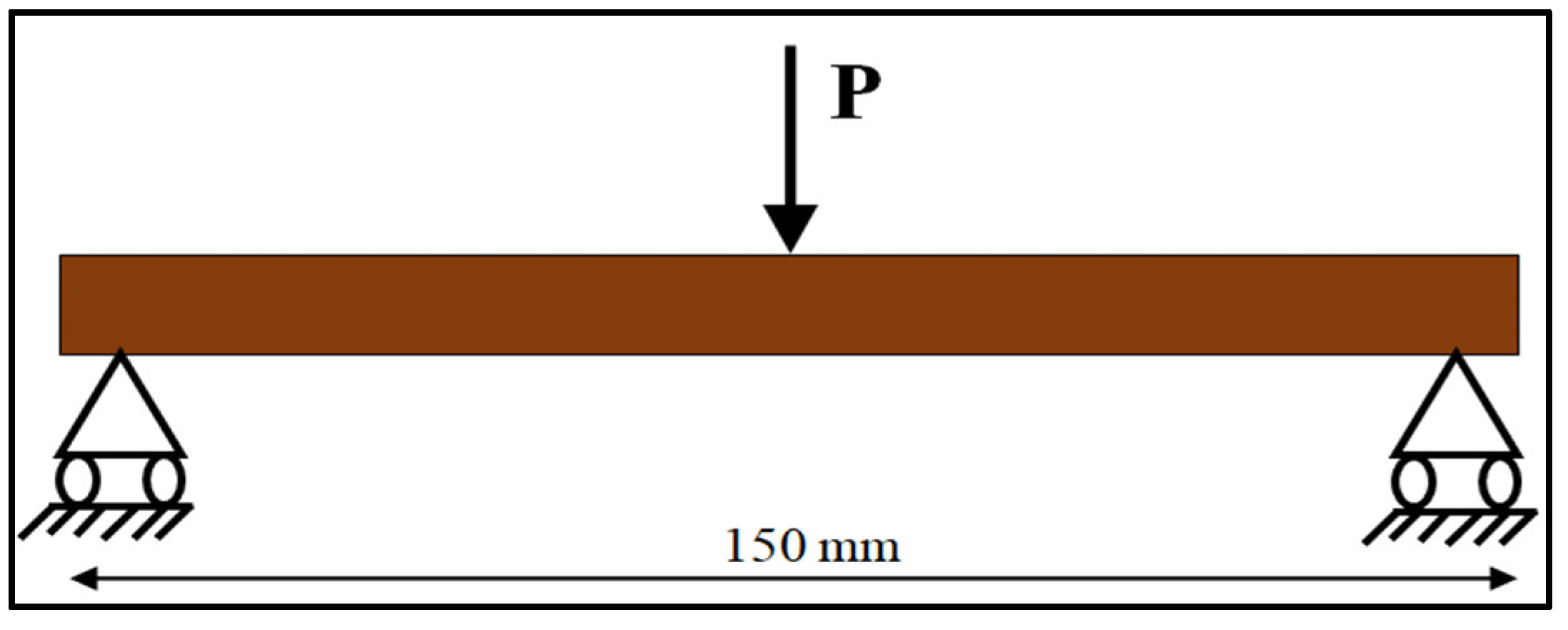
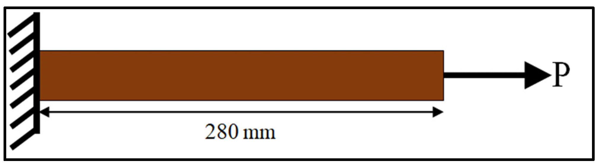
Composite panel strips were considered for modeling. The sizes of the composite panel strips were considered according to the ASTM standards, i.e., ASTM 3410, ASTM D790, and ASTM D3039 for compressive strength, flexural strength, and tensile strength, respectively. Specimen dimensions of 145 mm × 25 mm × 4 mm (length × width × thickness) were considered for the compressive test. Specimen dimensions of 150 mm × 25 mm × 4 mm (length × width × thickness) were considered for the flexural test. Specimen dimensions of 280 mm × 25 mm × 3 mm (length × width × thickness) were considered for the tensile test, as shown in Table 2. The geometry of all the components was drawn using computer-aided software AutoCAD, as shown in Figure 3, Figure 4 and Figure 5. The properties of the material considered for finite element modeling are considered in Table 1.
Table 2.
Dimensions of the composite panel strips.
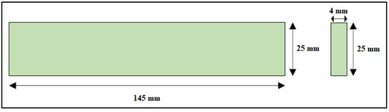
Figure 3.
Coconut inflorescence stem-fiber-reinforced composite specimen dimensions for the compressive test.
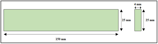
Figure 4.
Coconut inflorescence stem-fiber-reinforced composite specimen dimensions for the flexural test.

Figure 5.
Coconut inflorescence stem-fiber-reinforced composite specimen dimensions for the tensile test.
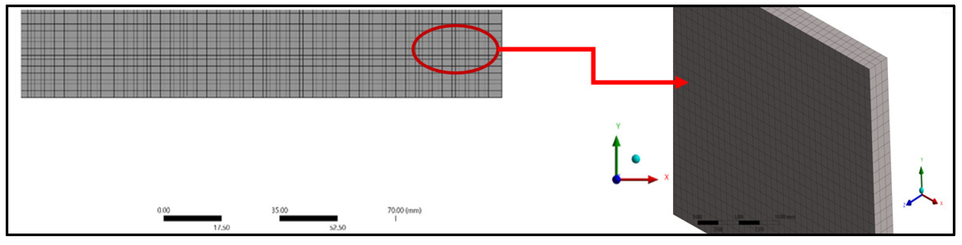
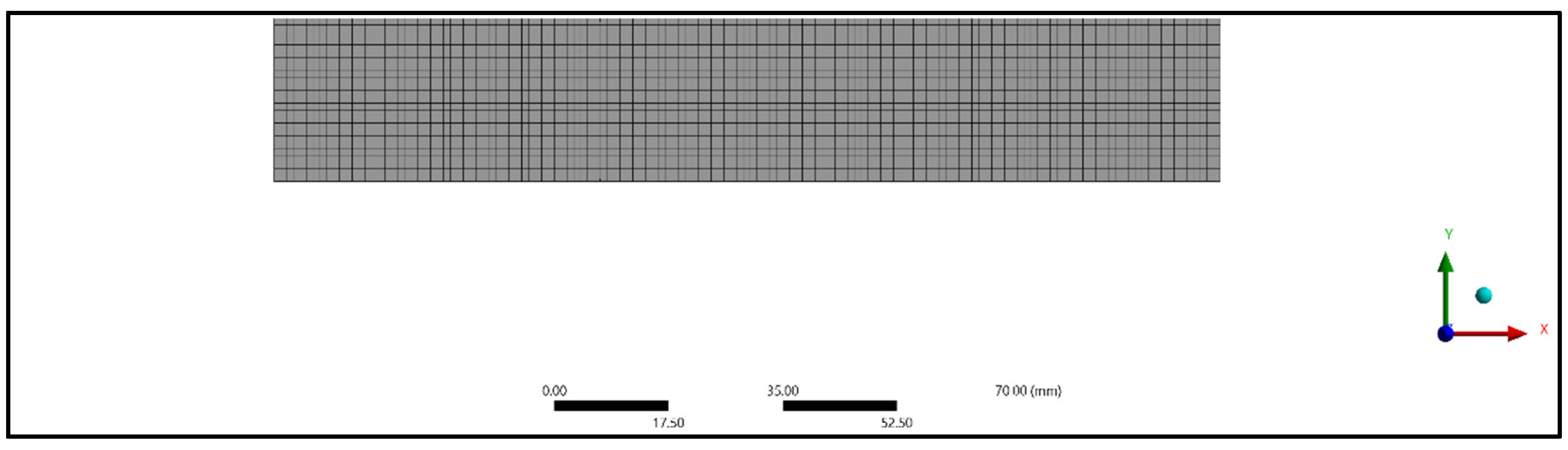
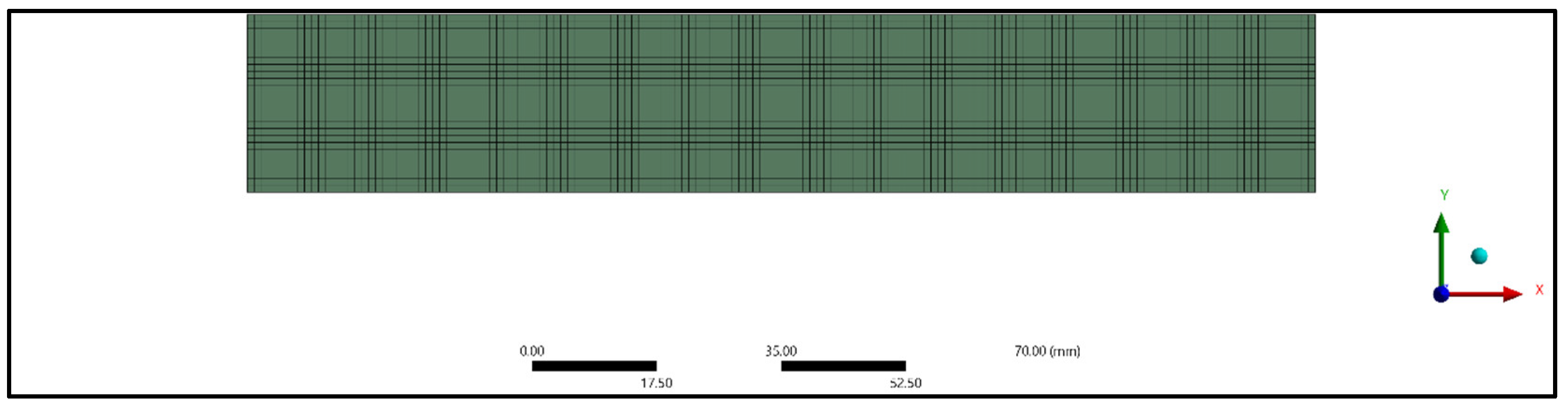
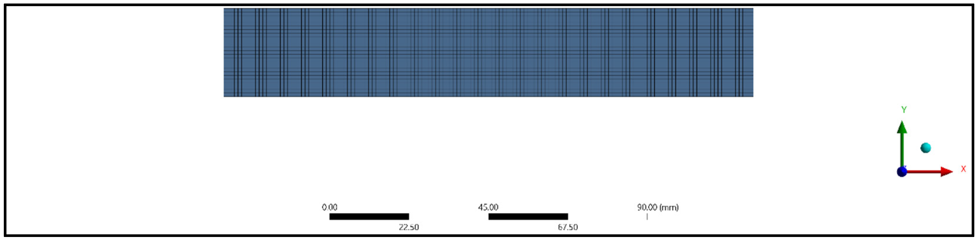
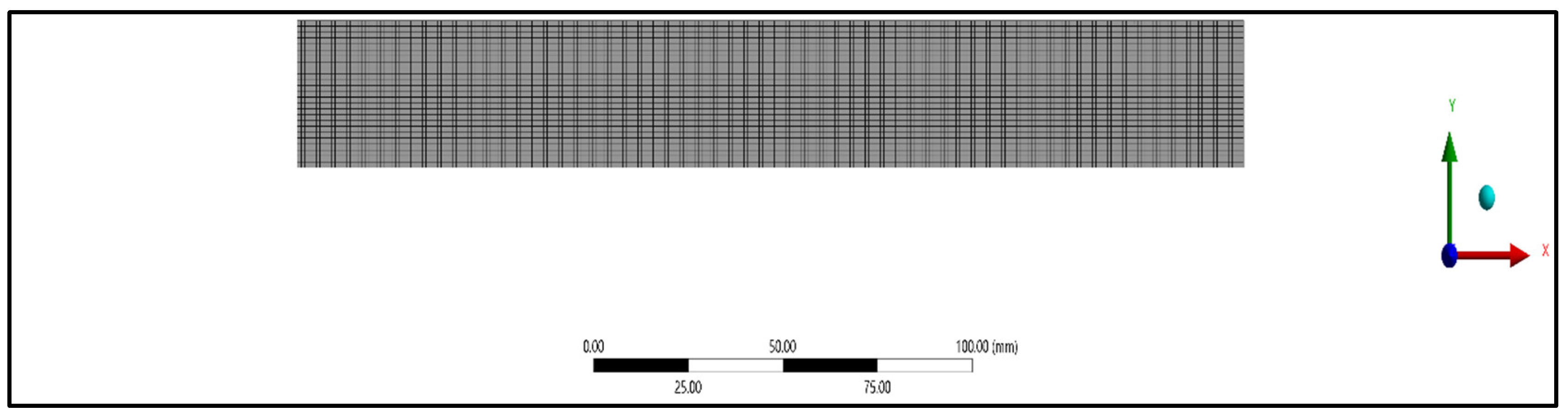
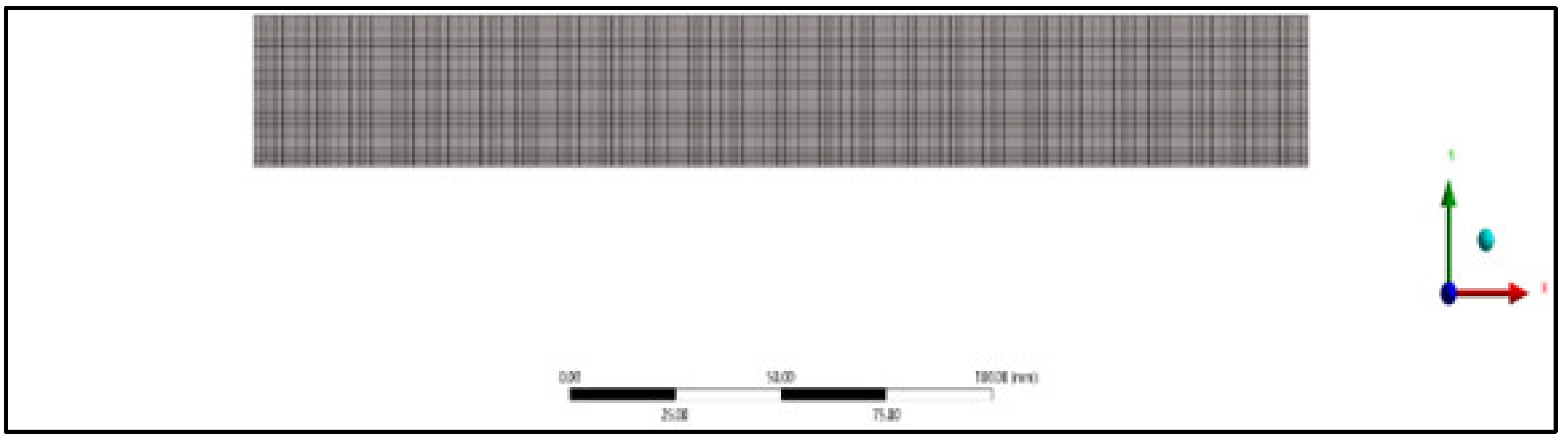
A three-dimensional analysis of the composite panel model was carried out with the help of finite element software ANSYS. The composite panel model was analyzed by employing static structural analysis. SOLID186 elements were considered to study the deformation of the composite panel for the tensile, compressive, and flexural specimens. A higher-order 20-node 3D solid element called SOLID186 displays quadratic displacement behavior. The twenty nodes each have three degrees of freedom—translations in the nodal x, y, and z directions. Plasticity, hyper elasticity, creep, stress stiffening, and large deflection are supported by the element shown in Figure 6. The nodes and elements were generated for tensile, compressive, and flexural specimens, as shown in Table 3. An element size of 1 mm was used for meshing. The meshed models considered for study are as shown in Figure 7, Figure 8, Figure 9, Figure 10, Figure 11 and Figure 12.
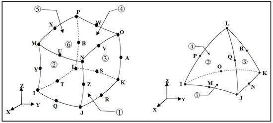
Figure 6.
SOLID186 element.
Table 3.
Nodes and elements of the composite panels.

Figure 7.
Meshing of compressive treated specimen.

Figure 8.
Meshing of compressive untreated specimen.
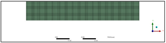
Figure 9.
Meshing of flexural treated specimen.
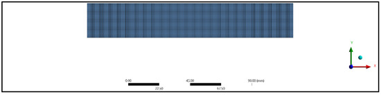
Figure 10.
Meshing of flexural untreated specimen.
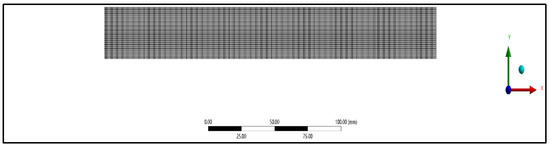
Figure 11.
Meshing of tensile treated specimen.
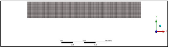
Figure 12.
Meshing of tensile untreated specimen.
The tensile and compressive models of the composite panel specimens had fixed support at one end, and an axial load was applied at the free end of the specimens. For the flexural model, both ends were pinned, and a concentered load was applied at the center of the specimen. The schematic representations of the boundary conditions considered for the models are shown in Figure 13, Figure 14 and Figure 15.
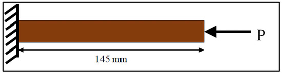
Figure 13.
Schematic representation for the compression model.
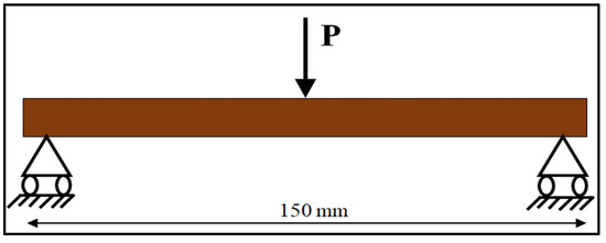
Figure 14.
Schematic representation for the flexural model.

Figure 15.
Schematic representation for the tensile model.
The increase in compression deformation with longer fiber lengths suggests that longer fibers may not provide as much resistance to compressive forces as compared to shorter fibers. This finding can have implications for applications where resistance to compression is crucial, such as load-bearing structures or components.
The decrease in flexural deformation with longer fiber lengths suggests that longer fibers contribute to increased stiffness and resistance to bending. This finding is valuable in applications where materials need to withstand bending loads, such as beams, panels, or structural components.
4. Results and Discussion
4.1. Finite Element Analysis
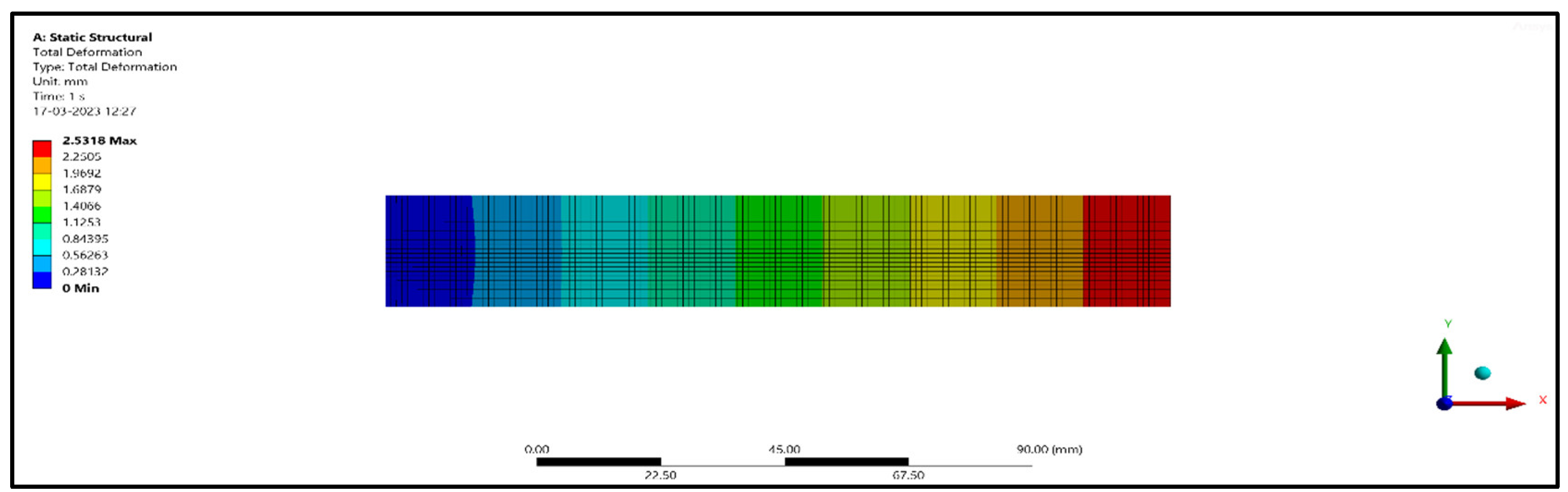
A static structural module was used to analyze the compression, flexure, and tensile models subjected to static load. The material properties and ultimate load used for the analysis was taken from the experimental results [6]. The finite element results obtained for the compression models, flexural models, and tensile model are given in Table 4, Table 5 and Table 6. The finite element results for these models are shown in Figure 16, Figure 17 and Figure 18.
Table 4.
Finite element analysis results for the compressive model.
Table 5.
Finite element analysis results for the flexural model.
Table 6.
Finite element analysis results for the tensile model.

Figure 16.
Deformation of the compressive specimen.
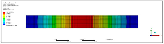
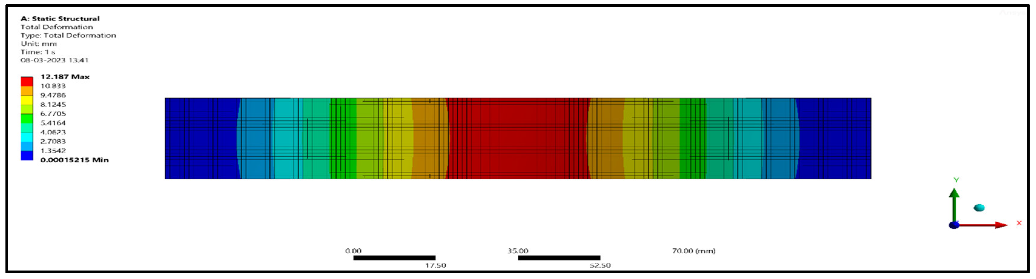
Figure 17.
Deformation of the flexural specimen.
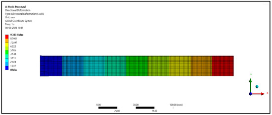
Figure 18.
Deformation of the tensile specimen.
From Table 4, it can be seen that for 5 mm length treated and untreated fibers, the deformations were 2.5318 mm and 2.4167 mm, and for 10 mm length treated and untreated fibers, the deformations were 3.5820 mm and 3.1114 mm, respectively. Similarly, for 15 mm treated and untreated fibers, the deformations were 3.9023 mm and 3.2557 mm. From the results, it is found that 15 mm length treated fibers deformed more when compared with 10 mm length fibers and 5 mm length fibers for compression specimens. From Table 5, it can be seen that for 5 mm length treated and untreated fibers, the deformations were 9.7546 mm and 9.3338 mm, and for 10 mm length treated and untreated fibers, the deformations were 12.187 mm and 11.113 mm, respectively. Similarly, for 15 mm treated and untreated fibers, the deformations were 11.807 mm and 9.8502 mm. From the results, it is found that 10 mm length treated fibers deformed more when compared with 15 mm length fibers and 5 mm length fibers for flexural specimens. From Table 6, it can be seen that for 5 mm length treated and untreated fibers, the deformations were 6.0876 mm and 5.7988 mm, and for 10 mm length treated and untreated fibers, the deformation were 8.3151 mm and 7.5591 mm, respectively. Similarly, for 15 mm treated and untreated fibers, the deformations were 9.3331 mm and 7.7365 mm. From the results, it is found that 15 mm length treated fibers deformed more when compared with 10 mm length fibers and 5 mm length fibers for flexural specimens.
The results in Table 4, Table 5 and Table 6 show that the 5 mm length untreated fibers contribute less deformation when compared with 10 mm and 15 mm length fibers. So as the fiber length decreases, the deformation value decreases, and as the length increases, the deformation value increases. The differentiation in deformation behavior between compression and flexural loading highlights the anisotropic nature of composite materials. Longer fibers, which tend to reduce flexural deformation, may be more suitable for applications where bending or flexing is a primary concern, as they provide greater stiffness. Shorter fibers, which can lead to increased compression deformation, may be preferred in applications where resistance to compressive forces is paramount.
4.2. Factor of Treatment of Fibers
When considering the factor of “treatment” in the context of compression deformation, the results show that treated specimens tend to exhibit slightly lower deformations compared to untreated specimens across different fiber lengths (5 mm, 10 mm, and 15 mm). For instance, in the 5 mm fiber length category, the “Treated” specimens had a deformation of 2.5318 mm, while the “Untreated” specimens had a slightly higher deformation of 2.805 mm. This trend is consistent across all tested fiber lengths.
In the tensile deformation tests, the factor of “treatment” also influences the magnitude of deformation. “Treated” specimens tend to display lower deformations compared to “Untreated” specimens across different fiber lengths. For instance, at the 5 mm fiber length, the “Treated” specimens had a tensile deformation of 6.0876 mm, while the “Untreated” specimens had a slightly higher deformation of 5.7988 mm. This trend was consistent across various fiber lengths. In the case of flexural deformation, a similar trend was observed. The “Treated” specimens generally exhibit lower deformations compared to the “Untreated” specimens across different fiber lengths. For example, at the 5 mm fiber length, the “Treated” specimens had a flexural deformation of 9.7546 mm, while the “Untreated” specimens had a slightly higher deformation of 9.3338 mm. This trend continues for other fiber lengths as well. The results suggest that the “treatment” of coconut inflorescence stem fibers has a noticeable effect on reducing the magnitude of deformation in compression, flexural, and tensile tests. The treatment process likely enhances the mechanical properties of the fibers, making them stiffer and more resistant to deformation under load. This could be due to factors such as improved fiber–matrix adhesion, reduced moisture absorption, or changes in the fiber’s microstructure. The consistency of this trend across different fiber lengths indicates that the “treatment” factor is effective in improving the mechanical performance of the composite panels under various loading conditions.
4.3. Validation of Finite Element Analysis Results against Experimental Results
Comparison of the finite element analysis results against the experimental results for compression, flexural, and tension models and fiber lengths of 5 mm, 10 mm, and 15 mm in treated and untreated fibers is provided in Table 7.
Table 7.
Comparison of the finite element analysis results against the experimental results for compression, flexural, and tensile specimen models.
For the 5 mm fiber length in the compression tests, the “Treated” specimens showed a deformation value of 2.531 mm in the FEA, while the experimental test resulted in a slightly higher deformation of 2.805 mm. This represents a 9.769% difference. Similarly, the “Untreated” specimens displayed a deformation value of 2.416 mm in the FEA, while the experimental test recorded a slightly higher deformation of 2.602 mm, resulting in a 7.121% difference.
In the compression testing, both the “Treated” and “Untreated” specimens showed slightly lower deformations in the FEA compared to the experimental results. The percentage differences indicate that the FEA tends to underestimate the deformations compared to real-world testing for compression in these specific conditions.
The flexural tests for the 5 mm fiber length and the “Treated” specimens resulted in a deformation value of 9.7546 mm in the FEA, while the experimental test recorded a slightly higher deformation of 2.805 mm. This represents a 9.769% difference. Similarly, for the “Untreated” specimens, the FEA showed a deformation of 9.3338 mm, whereas the experimental test resulted in a slightly higher deformation of 9.3338 mm, resulting in a 7.121% difference. In flexural testing, both the “Treated” and “Untreated” specimens showed deformations that were close between the FEA and experimental results. The percentage differences indicate a reasonably good agreement between the FEA and experimental results for flexural deformation in these specific conditions.
The comparison between FEA and experimental results provides insight into the accuracy and reliability of the numerical simulations for different loading conditions and material conditions. In compression testing, the FEA tends to underestimate the deformations compared to the experiments, indicating the need for potential adjustments or refinements in the FEA models to better predict compression behavior [17,18,19,20]. In contrast, the FEA results for flexural testing are closer to the experimental values, suggesting that the numerical simulations are reasonably accurate for this type of deformation. It is essential to consider these differences when using FEA for designing and analyzing structures involving similar materials and loading conditions. Further refinement of FEA models may be needed to improve their accuracy in compression testing [21,22,23].
5. Conclusions
Finite element analysis was carried out using ANSYS software for treated and untreated fibers with lengths of 5 mm, 10 mm, and 15 mm for compression, flexural, and tensile tests. The following conclusions were drawn from the FE analysis. Fiber length plays a vital role in contributing to the strength and deformation of the composite panels. The results show that the 5 mm length fibers underwent less deformation when compared with the 10 mm and 15 mm length fibers for compression, flexural, and tensile models. Finite element analysis results were found to be in good agreement with the experimental results. Longer fibers in a composite material provide more continuous and efficient load-bearing pathways. When a load is applied, longer fibers can distribute the stress over a larger area, reducing localized deformation. This is analogous to how longer steel cables in a suspension bridge can better distribute the load, leading to less sagging in the bridge deck. In composites, the fibers are responsible for carrying the majority of the applied load. Longer fibers allow for a greater number of load-bearing cross-links between the fibers and the matrix material. This enhances the stress transfer efficiency, reducing the risk of fiber–matrix debonding or slippage. In flexural (bending) tests, longer fibers increase the flexural rigidity of the composite material. This means that the material is more resistant to bending or deformation under a given load. Longer fibers create a stiffer and stronger structure. Longer fibers typically have a higher tensile strength. This means they can withstand higher pulling forces before breaking. In a tensile test, longer fibers can carry more load before experiencing failure, resulting in less deformation. The aspect ratio of the fibers (length to diameter) plays a vital role. Longer fibers with a high aspect ratio have a more significant effect on reducing deformation because they can span greater distances within the material. The microstructure of the composite, including the arrangement and orientation of fibers, influences how stress is distributed within the material. Longer fibers may align more effectively with the applied load, optimizing stress distribution. The interactions between the fiber and the matrix also play a significant role. Longer fibers may have more opportunities to form strong bonds with the matrix material, enhancing load transfer and reducing deformation. Longer fibers can enhance the overall structural integrity of the composite, reducing the tendency for the material to deform or fail under load.
Author Contributions
Conceptualization, M.N.; methodology, K.R.B.P.; software, R.R.M.; validation, M.N., K.R.B.P. and R.R.M.; formal analysis, R.R.M.; investigation, K.R.B.P.; resources, K.R.B.P.; data curation, K.R.B.P.; writing—original draft preparation, R.R.M.; writing—review and editing R.R.M. and P.H.; visualization, R.R.M.; supervision, M.N.; project administration, M.N. and P.H. All authors have read and agreed to the published version of the manuscript.
Funding
This research received no external funding.
Institutional Review Board Statement
Not applicable.
Informed Consent Statement
Not applicable.
Data Availability Statement
Not applicable.
Acknowledgments
The authors would also like to express their sincere gratitude to the editor and referees for their insightful comments and suggestions, which greatly improved the quality of this article. We would also like to express our gratitude to the RAISE conference organizers.
Conflicts of Interest
The authors declare no conflicts of interest.
References
- Adeniyi, A.G.; Onifade, D.V.; Ighalo, J.O.; Adeoye, A.S. A review of coir fiber reinforced polymer composites. Compos. Part B Eng. 2019, 176, 107305. [Google Scholar] [CrossRef]
- Ganesan, K.; Kailasanathan, C.; Rajini, N.; Ismail, S.O.; Ayrilmis, N.; Mohammad, F.; Al-Lohedan, H.A.; Tawfeek, A.M.; Issa, Z.A.; Aldhayan, D.M. Assessment on hybrid jute/coir fibers reinforced polyester composite with hybrid fillers under different environmental conditions. Constr. Build. Mater. 2021, 301, 124117. [Google Scholar] [CrossRef]
- Glouia, Y.; Chaabouni, Y.; El Oudiani, A.; Maatoug, I.; Msahli, S. Finite element analysis of mechanical response of cellulosic fiber-reinforced composites. Int. J. Adv. Manuf. Technol. 2019, 103, 4671–4680. [Google Scholar] [CrossRef]
- Gupta, U.S.; Dhamarikar, M.; Dharkar, A.; Tiwari, S.; Namdeo, R. Study on the effects of fibre volume percentage on banana-reinforced epoxy composite by finite element method. Adv. Compos. Hybrid Mater. 2020, 3, 530–540. [Google Scholar] [CrossRef]
- Muralidhar, N.; Kaliveeran, V.; Arumugam, V.; Srinivasula Reddy, I. A Study on Areca nut Husk Fibre Extraction, Composite Panel Preparation and Mechanical Characteristics of the Composites. J. Inst. Eng. (India) Ser. D 2019, 100, 135–145. [Google Scholar] [CrossRef]
- Nazeer, A. To Study the Mechanical Properties of Coconut Coir Fiber Reinforced with Epoxy Resin AW 106 & HV 953 IN. 2014; Volume 4. Available online: www.ijmer.com (accessed on 8 January 2024).
- Pagar, H.; Suryawanshi, S.R. Finite Element Analysis of Groundnut Shell and Coir Fiber Mix Epoxy Composite Moulding and Testing. Int. J. Sci. Res. Mech. Mater. Eng. 2021, 5, 17–20. [Google Scholar]
- Poornima, H.L.; Muralidhar, N.; Praveen, J.V. Mechanical characterization of areca fine fiber fabric (AFFF) reinforced epoxy composites. Mater. Today Proc. 2022, 66, 501–504. [Google Scholar] [CrossRef]
- Ramesh, M.; Sudharsan, P. Experimental Investigation of Mechanical and Morphological Properties of Flax-Glass Fiber Reinforced Hybrid Composite using Finite Element Analysis. Silicon 2018, 10, 747–757. [Google Scholar] [CrossRef]
- Gholampour, A.; Ozbakkaloglu, T. A review of natural fiber composites: Properties, modification and processing techniques, characterization, applications. J. Mater. Sci. 2020, 55, 829–892. [Google Scholar] [CrossRef]
- Dittenber, D.B.; GangaRao, H.V.S. Critical review of recent publications on use of natural composites in infrastructure. Compos. Part A Appl. Sci. Manuf. 2012, 43, 1419–1429. [Google Scholar] [CrossRef]
- Bazli, M.; Bazli, L. A review on the mechanical properties of synthetic and natural fiber-reinforced polymer composites and their application in the transportation industry. J. Compos. Compd. 2021, 3, 262–274. [Google Scholar]
- Madueke, C.; Umunakwe, R.; Mbah, O. A review on the factors affecting the properties of natural fiber polymer composites. Niger. J. Technol. 2022, 41, 55–64. [Google Scholar] [CrossRef]
- Verma, D.; Gope, P.; Maheshwari, M.K. Coir Fiber Reinforcement and Application in Polymer Composites: A Review. J. Mater. Environ. Sci. 2012, 4, 263–276. [Google Scholar]
- Gupta, U.S.; Dharkar, A.; Dhamarikar, M.; Choudhary, A.; Wasnik, D.; Chouhan, P.; Tiwari, S.; Namdeo, R. Study on the effects of fiber orientation on the mechanical properties of natural fiber reinforced epoxy composite by finite element method. Mater. Today Proc. 2021, 45 Pt 9, 7885–7893. [Google Scholar] [CrossRef]
- ASTM D790-15; Standard Test Methods for Flexural Properties of Unreinforced and Reinforced Plastics and Electrical Insulating Materials 1. ASTM: West Conshohocken, PA, USA, 2016. [CrossRef]
- Tezara, C.; Siregar, J.P.; Lim, H.Y.; Fauzi, F.A.; Yazdi, M.H.; Moey, I.K.; Lim, J.W. Factors that affect the mechanical properties of kenaf fiber reinforced polymer. J. Mech. Eng. Sci. 2016, 10, 2159–2175. [Google Scholar]
- Murthy, B.R.N.; Beedu, R.; Bhat, R.; Naik, N.; Prabakar, P. Delamination assessment in drilling basalt/carbon fiber reinforced epoxy composite material. J. Mater. Res. Technol. 2020, 9, 7427–7433. [Google Scholar] [CrossRef]
- Singh, H.; Singh, K.; Vardhan, S.; Sharma, S.M. A Critical Review of Mechanical and Wear Resistance Characterizations on Developed Aluminium Matrix Composite Reinforced With MgO Particulates. J. Comput. Mech. Manag. 2023, 2, 45–56. [Google Scholar] [CrossRef]
- Kowshik, S.; Gowrishankar, M.C.; Shettar, M.; Bhat, R.; Gurumurthy, B.M. Durability prediction analysis on mechanical properties of GFRP upon immersion in water at ambient temperature. Cogent Eng. 2021, 8, 1–16. [Google Scholar] [CrossRef]
- Naik, N.; Shivamurthy, B.; Thimmappa, B.H.S.; Jaladi, G.; Samanth, K.; Shetty, N. Recent advances in green composites and their applications. Eng. Sci. 2023, 21, 779. [Google Scholar] [CrossRef]
- Naik, N.; Shivamurthy, B.; Thimmappa, B.H.S.; Gupta, A.; Guo, J.Z.; Seok, I. A review on processing methods and characterization techniques of Green Composites. Eng. Sci. 2022, 20, 80–99. [Google Scholar] [CrossRef]
- Jain, K.; Agarwal, V.; Ahmad, S.S.; Mohapatra, S.; Srivastava, P.K.; Narasimha, D.B.; Bhat, R. Multi-parametric optimization of Wired Electrical Discharge machining process to minimize damage cause in steel—A soft computing based Taguchi-Grey Relation Analysis Approach. Eng. Sci. 2022, 20, 267–274. [Google Scholar] [CrossRef]


Disclaimer/Publisher’s Note: The statements, opinions and data contained in all publications are solely those of the individual author(s) and contributor(s) and not of MDPI and/or the editor(s). MDPI and/or the editor(s) disclaim responsibility for any injury to people or property resulting from any ideas, methods, instructions or products referred to in the content. |
© 2024 by the authors. Licensee MDPI, Basel, Switzerland. This article is an open access article distributed under the terms and conditions of the Creative Commons Attribution (CC BY) license (https://creativecommons.org/licenses/by/4.0/).