Proceeding Paper

Fluidic Properties of Diamond and SplitP Structures with Varying Porosity Levels in Tissue Engineering Applications: A Computational Fluid Dynamics Analysis †

by
Muhammad Noman Shahid
*,
Muhammad Mahabat Khan
,
Muhammad Usman Shahid
and
Shummaila Rasheed
Department of Mechanical Engineering, Capital University of Science and Technology (CUST), Islamabad 45750, Pakistan
*
Author to whom correspondence should be addressed.
Presented at the 4th International Conference on Advances in Mechanical Engineering (ICAME-24), Islamabad, Pakistan, 8 August 2024.
Eng. Proc. 2024, 75(1), 39; https://doi.org/10.3390/engproc2024075039
Published: 9 October 2024

Abstract

:
This study investigates the fluidic properties of the Diamond and SplitP structures with varying porosity levels (55%, 65%, and 75%) for tissue engineering applications using computational analysis. The scaffolds were designed using nTopology software and optimized to achieve the desired porosity and mechanical properties. The power law model was utilized to analyze blood as a non-Newtonian fluid. The study aims to optimize the scaffolds by observing fluidic characteristics such as permeability, pressure drop, and wall shear stress (WSS) to make them the optimal choice for bone tissue engineering applications. The results demonstrate that increasing porosity leads to higher permeability and lower pressure drop and WSS across the scaffolds. The findings suggest that the optimized Diamond and SplitP scaffolds with appropriate porosity levels can provide a suitable environment for cell adhesion, migration, proliferation, and differentiation, making them promising candidates for bone tissue engineering applications.

1. Introduction

In the field of tissue engineering, there has been a significant focus on the application of porous scaffolds for the regeneration and treatment of injured organs in recent years [1]. 3D printing, also known as additive manufacturing, has been extensively utilized in a range of medical uses, including prosthetics and implants. The current research focuses on bone implants, which can be manufactured utilizing Autograft or alternative materials like polymers, ceramics, and metals [2,3]. Designing a scaffold with an optimal architecture, which includes factors such as porosity, pore size, and pore shape, is a complex process. This complexity arises because the design parameters directly impact the mechanical and biocompatibility characteristics of the scaffolds [4].
Triply Periodic Minimal Surface (TPMS) structures are being explored for their potential use in 3D-printed bone implants, a lattice structure with repetitive surface patterns in three-dimensional space with zero mean curvature at each local point [1]. Evaluating the mechanism of fluid flow and its impact on permeability or wall shear stress (WSS) is crucial. This is because these parameters directly affect the cellular bioactivity within scaffolds. Dias et al. [5] conducted a computational and experimental analysis on scaffolds. The results revealed that by increasing the porosity and pore size, the permeability also increases. Another crucial aspect in simulating blood flow and evaluating its effects on WSS is considering the fluidic nature of blood. It is widely recognized that blood acts as a non-Newtonian fluid, especially at low shear rates, which are below 100 s 1 [6]. Marin and Lacroix carried out a study to examine the impact of structural variability in regular scaffolds across different samples on the magnitude and distribution of wall shear stress (WSS) through CFD simulations. Their findings revealed that geometric inconsistencies caused notable differences in both the velocity and WSS among the samples [7]. Researchers have used various numerical models such as the Carreau–Yasuda [8] and power law [9] models for non-Newtonian fluids. Davar et al. performed numerical investigation on different architectures to study their fluid flow behavior. The results showed that the permeability of the Diamond lattice outperforms the other scaffolds [10]. Ali and Sen conducted a CFD analysis on different type of scaffolds using the power law.
Previous studies in bone tissue engineering have extensively examined the Diamond scaffold, demonstrating its favorable properties for fluid dynamics and biocompatibility. However, the SplitP structure remains largely unexplored in the literature. Our research uniquely addresses this gap by developing and optimizing both the SplitP and Diamond TPMS scaffolds. A computational analysis was conducted to assess their fluidic characteristics, including permeability, pressure drop, and WSS. This study aimed to evaluate the SplitP scaffold in this context, offering novel insights and a direct comparison with the Diamond structure. Our findings aim to establish the optimal scaffold design for applications in bone tissue engineering.

2. Material and Methods

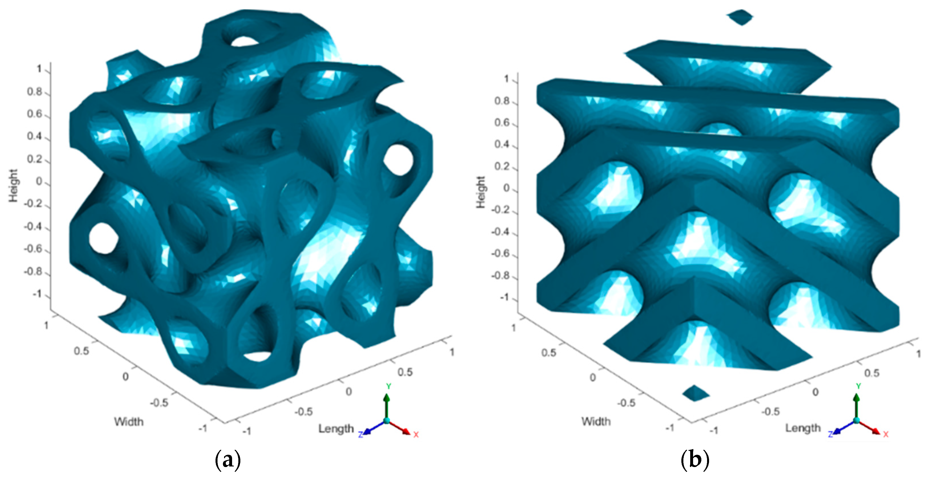
2.1. Scaffold Design

TPMS scaffolds, specifically the Diamond and SplitP structures, were designed using nTop 5.4.2 software. The scaffolds were created with three distinct porosities: 55%, 65%, and 75%, to investigate the effects of different porosity levels on the fluid flow and structural performance. The porosities of 55%, 65%, and 75% were selected as they represent a typical range for effective performance within the supported cellular structure responses, which commonly range from 50% to 90% [11]. The geometries were generated and optimized to achieve the desired porosity and mechanical properties. The resulting scaffold designs were then converted into a computational model with a tetrahedral unstructured mesh. CAD models for both structures are shown in Figure 1:

2.2. Governing Equations

The Navier–Stokes equation was employed to describe the behavior of an incompressible fluid with a constant density [10]:
ρ u t μ 2 u + ρ u . u + p = F
. u = 0
where u represents the velocity of the fluid, μ represents the dynamic viscosity, ∇ represents the del operator, p represents the pressure in Pascals, and F represents any additional forces acting on the fluid (such as gravity, although in this case F = 0) [12].
The power law model is utilized for calculating fluid viscosity to analyze blood as a non-Newtonian fluid [9]:
μ = K γ n 1 μ m i n < μ < μ m a x
where K ( k g . s n 2 / m ) indicates the consistency index, γ ( s 1 ) is the shear rate, n is the power law exponent, and μ m i n and μ m a x are the minimum and maximum viscosity cutoffs, respectively. The values selected for K and n were 0.017 and 0.708 mPa. s n , respectively. The power law model was selected for its ability to accurately characterize the rheological behavior of non-Newtonian fluids encountered in the CFD analysis of TPMS structures, providing a robust representation of the shear-thinning or shear-thickening properties observed in these fluids. This setting ensured that the viscosity calculated from the power law remained within a reasonable range during the computational investigation [13].
The permeability for non-Newtonian fluids can be calculated by [14]:
k = u K L p 1 / n
where u represents the fluid flow velocity at the inlet (m/s), L represents the length of the model (m), μ represents the dynamic fluid viscosity (kg/(m.s)), and Δp represents the pressure drop (Pa).
The Reynolds number for non-Newtonian fluids can be calculated by [14]:
R e = ρ u L μ a
where ρ ,   u ,   L , and μ a represent the density, fluid velocity, characteristic length, and apparent viscosity of the fluid, respectively. For this non-Newtonian fluid, the Reynolds number is calculated to be 0.064, signifying that the flow is within the laminar regime.

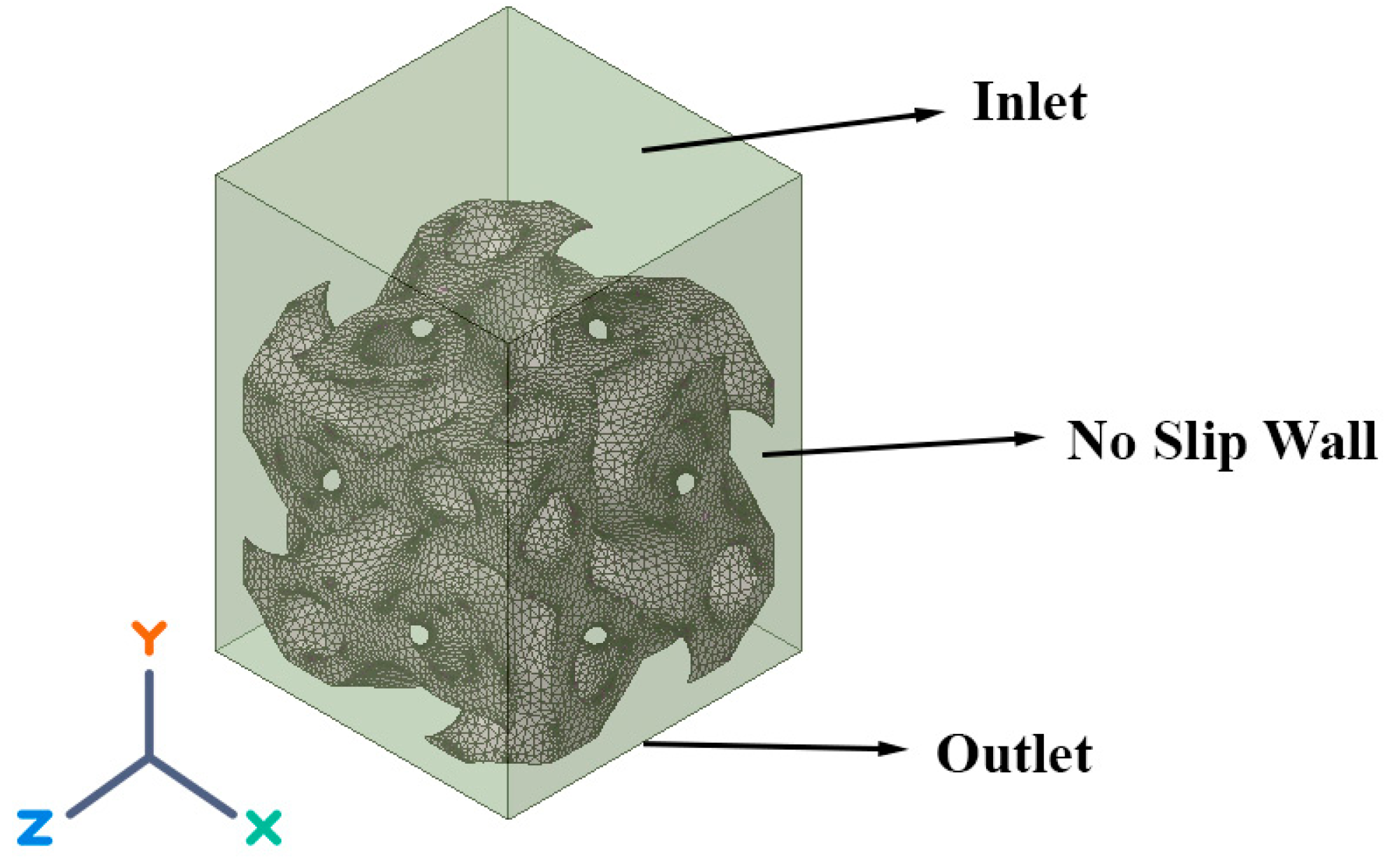
2.3. Discretization and Boundary Conditions

In the numerical investigation, the fluid flow within the TPMS scaffolds was simulated to evaluate their performance under physiological conditions. To ensure grid independence, a mesh sensitivity analysis was performed using element sizes of 0.5, 0.7, and 1 mm. A mesh size of 0.7 mm resulted in minimal variation (<3%) in the WSS, confirming the grid independence for further simulations. The flow conditions were replicated by assigning a velocity of 0.7 mm/s to the inlet. The scaffold walls were subjected to no-slip boundary conditions. To ensure an accurate flow simulation, a zero gauge pressure condition was imposed at the outlet, as shown in Figure 2. The viscous model employed was laminar flow, suitable for the low Reynolds number regime typical of physiological conditions. Blood, treated as a non-Newtonian fluid, was modeled using a power law relationship to account for its shear-thinning behavior. The computational approach utilized a coupled scheme with first-order upwind discretization methods to solve the governing equations of fluid flow. This method provided a robust and stable solution, ensuring an accurate representation of the fluid dynamics within the scaffolds.

3. Validation Study

The current numerical methodology has been validated by comparing its results with those reported in the existing literature. Specifically, we compared the results of the Gyroid structure for permeability with the study by Ali and Sen [14], who utilized the power law model for their analysis. Our results show good agreement with those obtained by Ali and Sen [14], indicating a high level of accuracy. Figure 3 demonstrates the validation of our numerical approach for determining the permeability of the Gyroid structure.

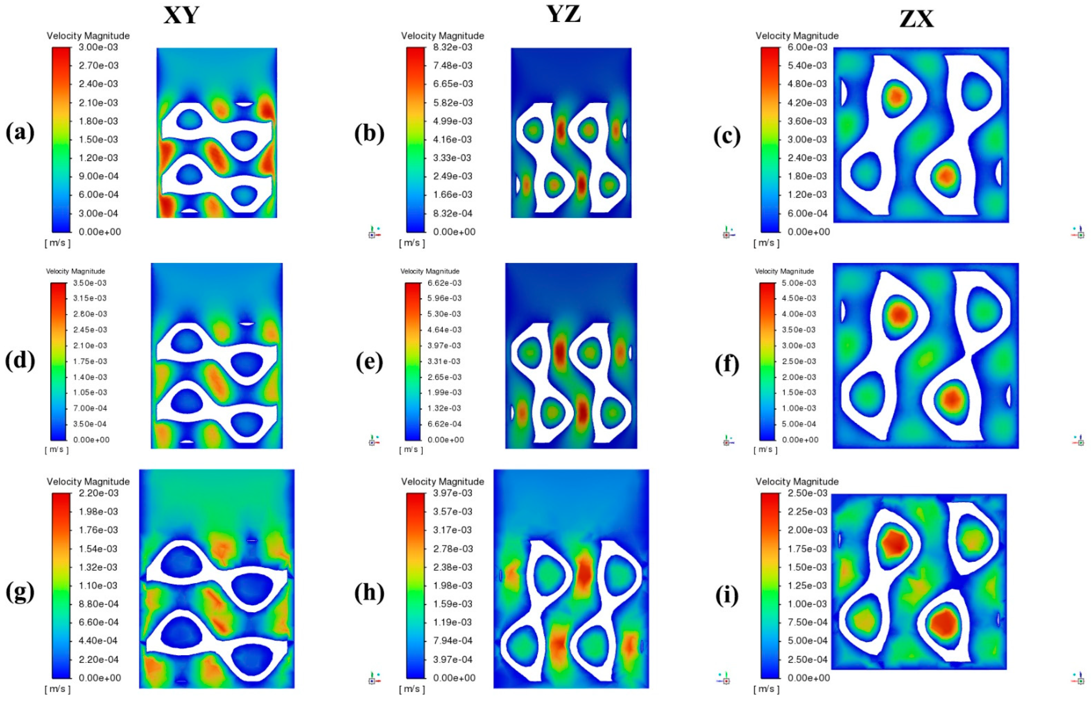
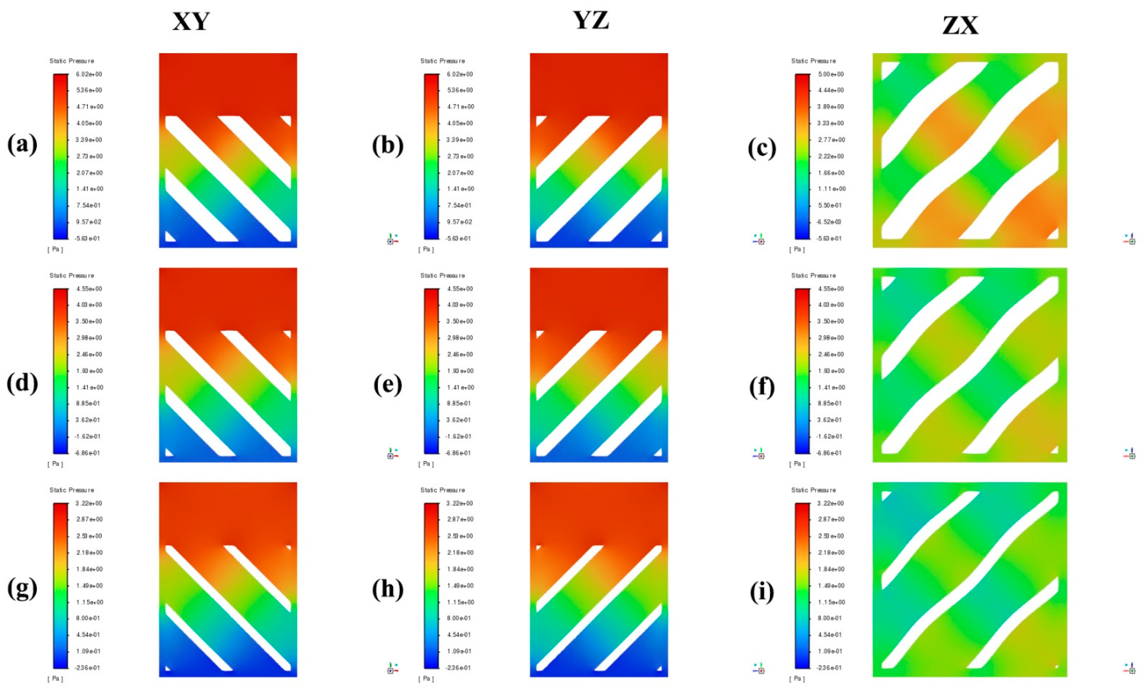
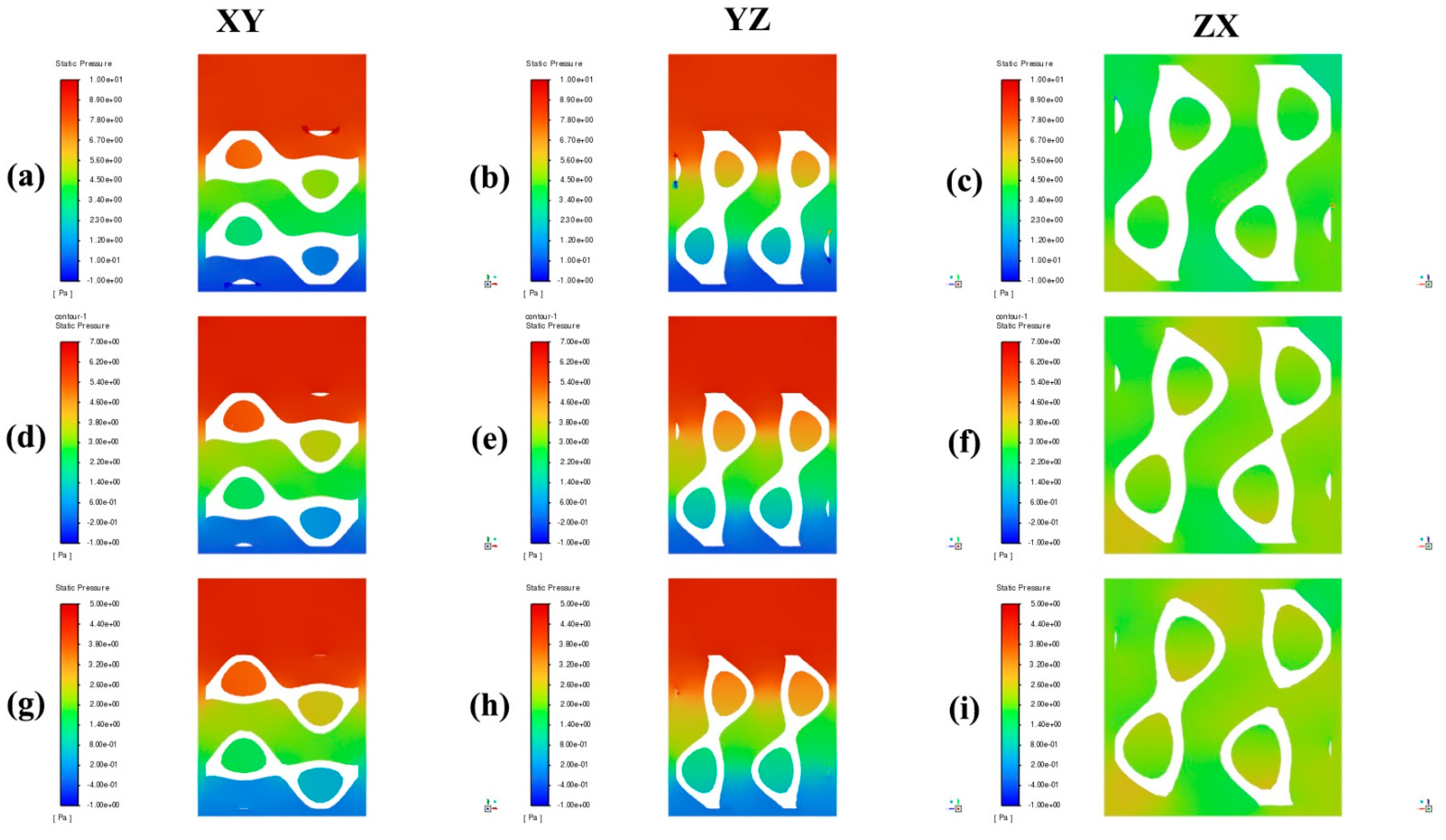
4. Results and Discussion

The CFD analysis of the SplitP and Diamond TPMS scaffolds revealed that increasing the porosity enhances the permeability and reduces the pressure drop, which is crucial for effective nutrient delivery and waste removal in tissue engineering. Specifically, scaffolds with 75% porosity exhibited the highest permeability and the lowest pressure drop, confirming that higher porosity facilitates a smoother fluid flow. The WSS decreased with increasing porosity, with the lowest WSS observed in scaffolds with 75% porosity. Figure 4 and Figure 5 show the velocity contour of Diamond and SplitP with varying porosity levels from 55 to 75% with an increment of 10, respectively. In Figure 4, 55% porosity shows that the fluid flow is more uniform, with higher velocities concentrated in the spaces between solid sections, indicating smoother and broader high-velocity regions across the XY, YZ, and ZX planes. As porosity increases to 65%, the overall velocity magnitude decreases, and high-velocity regions become more localized, showing distinct channels where the fluid prefers to flow. At 75% porosity, this effect is further pronounced, with narrow and irregular high-velocity pathways, suggesting that higher porosity constrains the fluid to more complex and less predictable pathways. In Figure 5, 55% porosity shows that higher velocities are concentrated around the openings within the structure, with smooth and relatively uniform flow patterns. As porosity increases to 65%, the overall velocity magnitudes decrease, and high-velocity regions become more localized around structural voids, indicating that the fluid flow prefers specific pathways. At 75% porosity, the velocity magnitudes further decrease, and the flow becomes constrained to narrow regions with more complex and irregular patterns. Figure 6 and Figure 7 show the pressure contours of Diamond and SplitP, which show that the pressure decreases as the porosity increases, which agrees with previous studies [5,14,15]. In Figure 6, as the porosity increases from 55% to 75%, the pressure decreases and the low-pressure regions become more pronounced, especially along diagonal channels, with the ZX plane showing the most complex patterns. Similarly, Figure 7 shows that a higher porosity (from 55% to 75%) results in a lower overall pressure and larger, more irregular low-pressure areas around split channels, with the ZX plane again displaying the most complex patterns. Both the Diamond and SplitP structures showed similar trends, but the Diamond structure generally had slightly higher permeability and a lower pressure drop, making it potentially more suitable for applications requiring higher fluid transport efficiency. Wall shear stress (WSS) refers to the tangential force exerted by fluid flow on a surface. In bone tissue engineering, the WSS is significant because it influences cell behavior, proliferation, and differentiation, which are crucial for effective bone regeneration and tissue formation [10]. Increasing the porosity in TPMS scaffolds reduces the velocity and wall shear stress (WSS), which aids in initial cell adhesion and growth. However, optimal cell differentiation requires a balance of nutrient transport and mechanical stimuli. While both studied structures showed similar trends in fluid dynamics, the Diamond structure outperformed in terms of a lower pressure drop and higher permeability, making it more suitable for applications needing efficient fluid transport. Overall, a higher porosity enhances the fluid flow, reduces the pressure drop, and improves the scaffold’s suitability for tissue engineering. For clarity, the x-axis represents length, the y-axis represents height, and the z-axis represents width throughout the following contour plots in the XY, YZ, and ZX planes.
Figure 8a shows the trend for porosity versus permeability for the SplitP and Diamond structures with different porosity levels. It shows that the permeability increases as the porosity increases for both structures because the higher porosity allows a more effective transport of fluids through the structure, reducing the resistance to fluid flow [5,14]. Figure 8b shows the trend for porosity versus pressure drop for the SplitP and Diamond structures with different porosity levels (55, 65, and 75%). It shows that as the porosity increases, the pressure drop decreases because there are more pathways for fluids to flow through the structure as porosity increases [1,14]. Figure 8c shows porosity versus WSS for the SplitP and Diamond structures, and it shows that by increasing the porosity, the WSS decreases for both structures, because increasing the porosity can result in the creation of additional pathways for fluid flow. This, in turn, can lead to a reduction in the velocity of the fluid near the walls and potentially result in a decrease in the WSS.

5. Conclusions

In this study, the fluid flow and structural performance of TPMS scaffolds were analyzed using CFD simulations. The focus was on two specific designs, Diamond and SplitP, each examined at porosities of 55%, 65%, and 75%. The analysis revealed several key findings regarding permeability, WSS, and pressure drop:
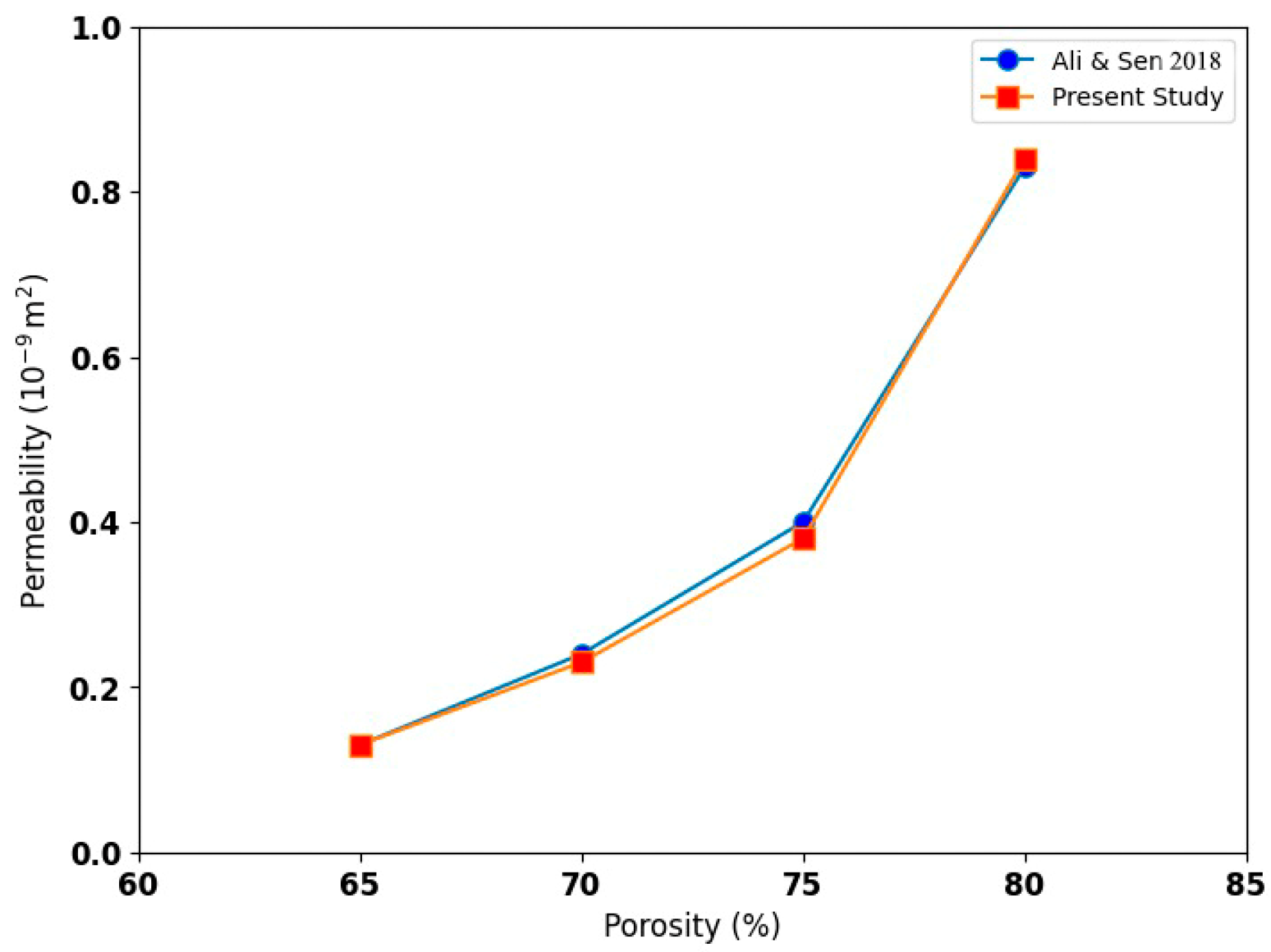
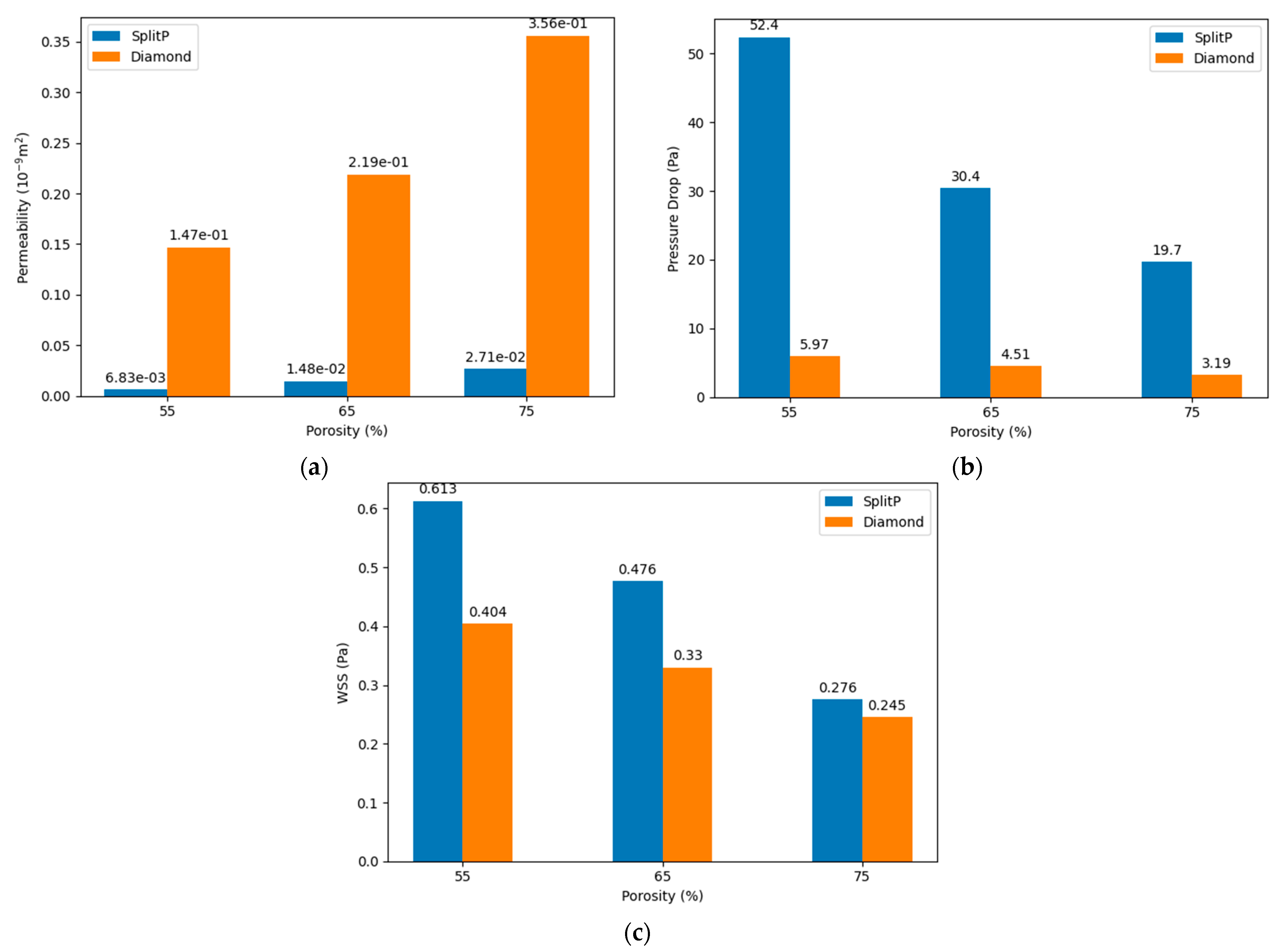
  • Increasing the porosity significantly enhances the permeability within TPMS scaffolds. Scaffolds with 75% porosity demonstrated the highest permeability, facilitating superior fluid transport, which is essential for efficient nutrient delivery and waste removal. Among the designs analyzed, the Diamond structure generally exhibited slightly higher permeability compared to the SplitP structure, suggesting that it is more effective for applications requiring optimal fluid flow.
  • Higher porosity in TPMS scaffolds significantly reduces the pressure drop across the structure. Both the Diamond and SplitP scaffolds exhibited the lowest pressure drop at 75% porosity, which is essential for effective nutrient delivery and waste removal in tissue engineering applications. Among the two designs, the Diamond structure consistently demonstrated a lower pressure drop than the SplitP structure, making it more efficient for applications that demand minimal resistance to fluid flow.
  • The WSS decreases as the porosity increases, with the lowest values observed at 75% porosity. A lower WSS is favorable for initial cell adhesion, although optimal differentiation requires adjustments to the porosity.

Author Contributions

Conceptualization, M.N.S., M.M.K., M.U.S. and S.R.; methodology, M.N.S., M.M.K. and M.U.S.; software, M.N.S. and M.U.S.; validation, M.N.S., M.M.K., M.U.S. and S.R.; formal analysis, M.N.S., M.M.K., M.U.S. and S.R.; investigation, M.N.S., M.M.K., M.U.S. and S.R.; writing—original draft preparation, M.N.S. and M.U.S.; writing—review and editing, M.N.S., M.M.K., M.U.S. and S.R.; visualization, M.N.S., M.M.K., M.U.S. and S.R.; supervision, M.M.K.; project administration, M.N.S. and M.M.K. All authors have read and agreed to the published version of the manuscript.

Funding

This research received no external funding.

Institutional Review Board Statement

Not Applicable.

Informed Consent Statement

Not Applicable.

Data Availability Statement

The original contributions presented in the study are included in the article; further inquiries can be directed to the corresponding author.

Conflicts of Interest

The authors declare no conflicts of interest.

References

  1. Shahid, M.N.; Shahid, M.U.; Rasheed, S.; Irfan, M.; Obeidi, M.A. Computational Investigation of the Fluidic Properties of Triply Periodic Minimal Surface (TPMS) Structures in Tissue Engineering. Designs 2024, 8, 69. [Google Scholar] [CrossRef]
  2. Sidambe, A.T. Biocompatibility of Advanced Manufactured Titanium Implants-A Review. Materials 2014, 7, 8168–8188. [Google Scholar] [CrossRef] [PubMed]
  3. Zuniga, J.; Katsavelis, D.; Peck, J.; Stollberg, J.; Petrykowski, M.; Carson, A.; Fernandez, C. Cyborg Beast: A Low-Cost 3d-Printed Prosthetic Hand for Children with Upper-Limb Differences. BMC Res. Notes 2015, 8, 10. [Google Scholar] [CrossRef] [PubMed]
  4. Hutmacher, D.W.; Schantz, J.T.; Lam, C.X.F.; Tan, K.C.; Lim, T.C. State of the Art and Future Directions of Scaffold-Based Bone Engineering from a Biomaterials Perspective. J. Tissue Eng. Regen. Med. 2007, 1, 245–260. [Google Scholar] [CrossRef] [PubMed]
  5. Dias, M.R.; Fernandes, P.R.; Guedes, J.M.; Hollister, S.J. Permeability Analysis of Scaffolds for Bone Tissue Engineering. J. Biomech. 2012, 45, 938–944. [Google Scholar] [CrossRef] [PubMed]
  6. Berger, S.A.; Jou, L.D. Flows in Stenotic Vessels. Annu. Rev. Fluid. Mech. 2000, 32, 347–382. [Google Scholar] [CrossRef]
  7. Marin, A.C.; Lacroix, D. The Inter-Sample Structural Variability of Regular Tissue-Engineered Scaffolds Significantly Affects the Micromechanical Local Cell Environment. Interface Focus 2015, 5, 20140097. [Google Scholar] [CrossRef] [PubMed]
  8. Jiang, Y.; Zhang, J.; Zhao, W. Effects of the Inlet Conditions and Blood Models on Accurate Prediction of Hemodynamics in the Stented Coronary Arteries. AIP Adv. 2015, 5, 57109. [Google Scholar] [CrossRef]
  9. Nadeem, S.; Akbar, N.S.; Hendi, A.A.; Hayat, T. Power Law Fluid Model for Blood Flow through a Tapered Artery with a Stenosis. Appl. Math. Comput. 2011, 217, 7108–7116. [Google Scholar] [CrossRef]
  10. Ali, D.; Ozalp, M.; Blanquer, S.B.G.; Onel, S. Permeability and Fluid Flow-Induced Wall Shear Stress in Bone Scaffolds with TPMS and Lattice Architectures: A CFD Analysis. Eur. J. Mech. B Fluids 2020, 79, 376–385. [Google Scholar] [CrossRef]
  11. Bobbert, F.S.L.; Zadpoor, A.A. Effects of Bone Substitute Architecture and Surface Properties on Cell Response, Angiogenesis, and Structure of New Bone. J. Mater. Chem. B 2017, 5, 6175–6192. [Google Scholar] [CrossRef]
  12. Vossenberg, P.; Higuera, G.A.; Van Straten, G.; Van Blitterswijk, C.A.; Van Boxtel, A.J.B. Darcian Permeability Constant as Indicator for Shear Stresses in Regular Scaffold Systems for Tissue Engineering. Biomech. Model. Mechanobiol. 2009, 8, 499–507. [Google Scholar] [CrossRef]
  13. Johnston, B.M.; Johnston, P.R.; Corney, S.; Kilpatrick, D. Non-Newtonian Blood Flow in Human Right Coronary Arteries: Steady State Simulations. J. Biomech. 2004, 37, 709–720. [Google Scholar] [CrossRef]
  14. Ali, D.; Sen, S. Permeability and Fluid Flow-Induced Wall Shear Stress of Bone Tissue Scaffolds: Computational Fluid Dynamic Analysis Using Newtonian and Non-Newtonian Blood Flow Models. Comput. Biol. Med. 2018, 99, 201–208. [Google Scholar] [CrossRef] [PubMed]
  15. Ma, S.; Tang, Q.; Han, X.; Feng, Q.; Song, J.; Setchi, R.; Liu, Y.; Liu, Y.; Goulas, A.; Engstrøm, D.S.; et al. Manufacturability, Mechanical Properties, Mass-Transport Properties and Biocompatibility of Triply Periodic Minimal Surface (TPMS) Porous Scaffolds Fabricated by Selective Laser Melting. Mater. Des. 2020, 195, 109034. [Google Scholar] [CrossRef]
Figure 1. CAD models at 55% porosity: (a) SplitP scaffold; (b) Diamond scaffold.
Engproc 75 00039 g001
Figure 2. Boundary conditions on scaffolds.
Engproc 75 00039 g002
Figure 3. Comparison of permeability results for the Gyroid structure [14].
Engproc 75 00039 g003
Figure 4. Velocity contour for the Diamond structure at (ac) 55% porosity, (df) 65% porosity, and (gi) 75% porosity.
Engproc 75 00039 g004
Figure 5. Velocity contour for the SplitP structure at (ac) 55% porosity, (df) 65% porosity, and (gi) 75% porosity.
Engproc 75 00039 g005
Figure 6. Pressure contour for the Diamond structure at (ac) 55% porosity, (df) 65% porosity, and (gi) 75% porosity.
Engproc 75 00039 g006
Figure 7. Pressure contour for the SplitP structure at (ac) 55% porosity, (df) 65% porosity, and (gi) 75% porosity.
Engproc 75 00039 g007
Figure 8. (a) Porosity vs. permeability; (b) porosity vs. pressure drop; (c) porosity vs. WSS.
Engproc 75 00039 g008
Disclaimer/Publisher’s Note: The statements, opinions and data contained in all publications are solely those of the individual author(s) and contributor(s) and not of MDPI and/or the editor(s). MDPI and/or the editor(s) disclaim responsibility for any injury to people or property resulting from any ideas, methods, instructions or products referred to in the content.

