Proceeding Paper

Novel Control-like Approach for the Robust Integration of Functional Mock-Up Units into Digital Twins †

by
Raphael Gebhart
*,‡ and
Corentin Lepais
German Aerospace Center (DLR), Münchener Straße 20, 82234 Wessling, Germany
*
Author to whom correspondence should be addressed.
Presented at the 14th EASN International Conference on “Innovation in Aviation & Space towards sustainability today & tomorrow”, Thessaloniki, Greece, 8–11 October 2024.
These authors contributed equally to this work.
Eng. Proc. 2025, 90(1), 12; https://doi.org/10.3390/engproc2025090012
Published: 11 March 2025

Abstract

:
A novel approach for the robust integration of Functional Mock-up Units (FMUs) into Modelica is proposed, which maintains the computational robustness of the Modelica base model and minimizes the simulation time. Using a control-like approach, the base model is retained and mimics the FMU outputs. On the one hand, the controller can be interpreted as a numerical tool designed to provide a correct steady-state solution and minimize transient errors. On the other hand, the additional low-pass filter can also be used to represent the inertia of a system. The application of this easy-to-implement approach is demonstrated for a digital twin of the overall thermal management system (TMS) of a future hybrid electrical regional aircraft, which aims at identifying critical conditions and flight cases in advance of hardware tests and virtually demonstrating the behavior of the TMS during complete flight missions. To this end, a base model of the TMS is first set up using the Thermofluid Stream Modelica Library, which focuses on computational robustness, in order to define the boundaries and interfaces of the different subsystems. Then, the subsystems are gradually replaced by validated FMUs to enable virtual demonstrations, where the novel control-like approach proves to be crucial.

1. Introduction

Reducing greenhouse gas emissions from aircraft is one of the biggest challenges facing the aviation industry, which is why a number of research projects are focusing more on battery or fuel-cell-powered electric aircraft. Currently, a regional aircraft produces waste heat of about  50 k W  [1]. However, if more electric aircraft powered by fuel cells are considered, the waste heat can reach several M W  [2] and the thermal management system (TMS) is a key enabler. As part of the European Clean Aviation project TheMa4HERA (Thermal Management for Hybrid Electric Regional Aircraft), the German Aerospace Center (DLR) is developing a digital twin of TMS for future hybrid electric regional aircraft. This digital twin will be used to test different TMS architectures, to identify critical conditions and flight cases in advance of hardware tests and to virtually demonstrate the overall TMS at a system level during full gate-to-gate missions for different environmental conditions. It is expected that the knowledge gained about the overall TMS will lead to the early detection of potential design problems, contributing to the development of a better system design and aiding in certification. The combination of hardware tests for component validation and virtual tests for system demonstration makes it possible to save time, to prepare flight and ground demonstrations in advance, and to increase the technology readiness level.
The TMS system in TheMa4HERA is divided into three subsystems:
  • Environmental control system (ECS)
  • Fuel cell cooling system
  • Power electronics and battery cooling system
For each subsystem, new technologies and architectures are developed and evaluated at the aircraft level in terms of, e.g., weight, drag, or power consumption. This work deals with the digital twin of ECS, but the same approach will be applied to the other subsystems. First, a base model focused on computational robustness is developed, which is introduced in Section 2. Then, the components of the base model are replaced by high-fidelity models validated by hardware tests. In this context, Section 3 proposes a new approach for the integration of high-fidelity FMUs through the example of the outflow valve model. Finally, Section 4 and Section 5 show exemplary results of the digital twin for complete gate-to-gate mission in different environmental conditions and discuss the approach for the integration of high-fidelity FMUs.

2. Digital Twin Base Model of the Environmental Control System

The digital twin is modelled using the object-oriented modelling language Modelica [3], which has already proven to be capable of modeling digital twins [4,5]. In addition, the open-source DLR ThermoFluid Stream Library (TFS) is used, as it enables fast and robust modelling of complex thermofluid architectures by avoiding non-linear systems of equations [6,7] and provides various generic models of, e.g., compressors, heat exchangers, or valves, which can then be combined to form the final model.
Figure 1 shows a schematic of the digital twin architecture, consisting of the mission profile and atmosphere, two controlled ECS packs in parallel for redundancy purposes, the pressurised fuselage, and the outflow valve for pressure control.
First, a mission profile block defines the gate-to-gate mission, i.e., altitude and speed over time, as well as the setpoints for the various controllers of, e.g., the cabin temperature, cabin pressure, and fresh air mass flow rate. Then, an International Standard Atmosphere (ISA) model provides the ambient temperature, pressure, and Mach number based on the altitude, speed, and ground conditions. Additionally, the absolute humidity is calculated on the basis of the relative humidity, which is assumed to be independent of altitude. Finally, solar radiation is linearly interpolated on the basis of a cloud factor, assuming no clouds above a certain altitude. The environmental conditions are then used, e.g., from the ECS pack, as boundary conditions for heat and mass flows.
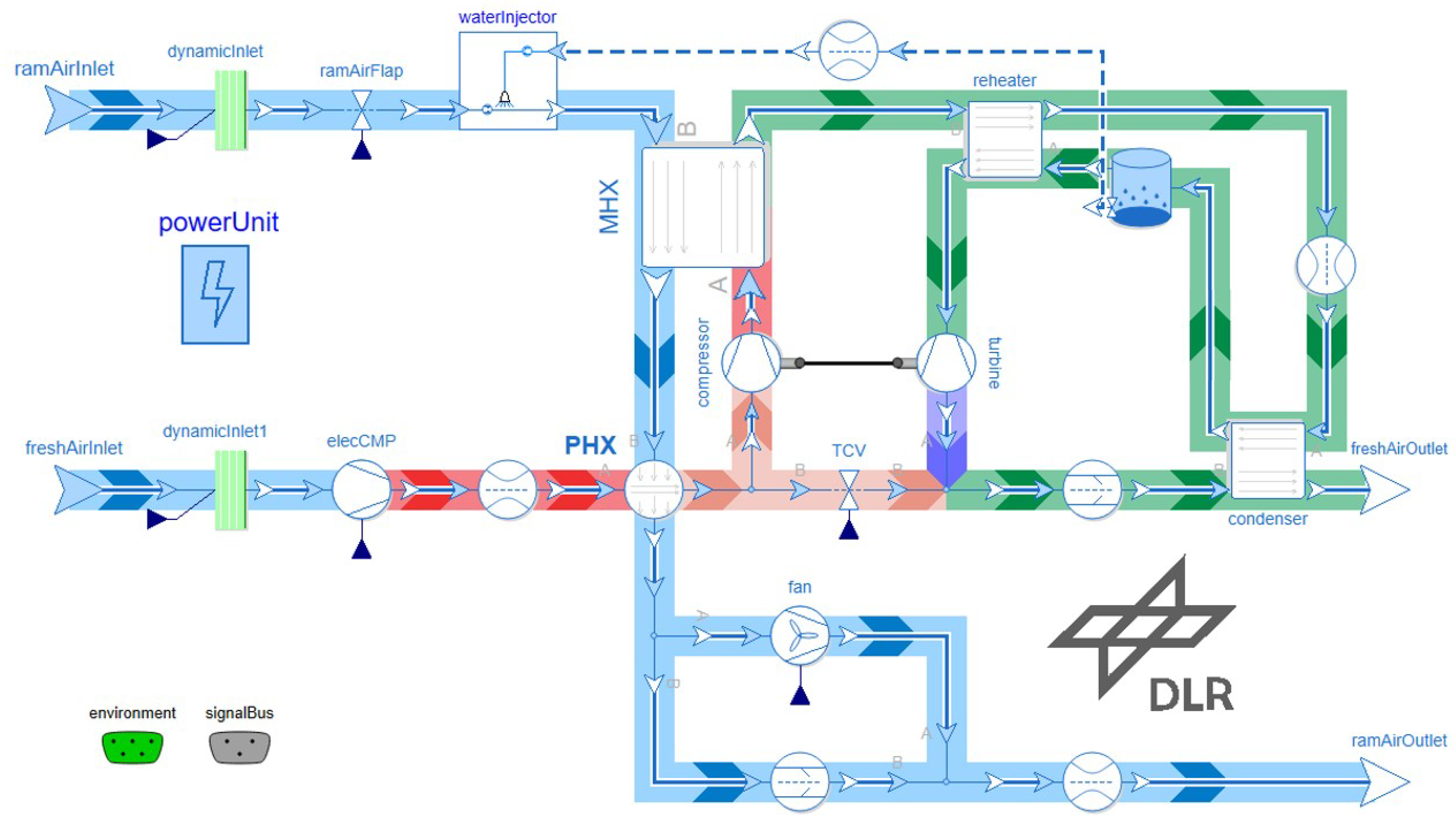
Figure 2 shows the ECS pack architecture of an electrically driven bleedless bootstrap cycle similar to [8], that is used for the base model of the digital twin. This common ECS pack architecture is, in current aircraft, often driven by the bleed air of the engine as a fresh air source [8,9]. To reduce the fuel consumption of a more electric aircraft, the bleed air can be replaced by ram air, which then has to be compressed by an electrically driven compressor, as, e.g., already integrated in the Boeing 787 Dreamliner [10]. After the electric compressor, pressurized fresh air is cooled in the primary heat exchanger (PHX) and split between the air cycle machine and the temperature control valve (TCV). In the air cycle machine, the air is once more compressed, cooled inside the main heat exchanger (MHX), and expanded inside a turbine, which drives the second compressor. Then, the expanded air is mixed with bypassed air through the TCV to achieve precise temperature control. To obtain sub-zero turbine outlet temperatures without icing, the air is dehumidified by the reheater, the condenser, and the water separator before entering the turbine. High-pressure dehumidification is crucial to prevent the cabin from fogging, especially for hot environmental conditions on the ground. Furthermore, the separated liquid water can be injected into the ram air flow to decrease its temperature and thereby increase the heat exchangers efficiencies. The cooling capacity is thereby mainly influenced by the ram air flow, which is controlled by a fan on the ground and by the ram air flap during cruising. Additionally, the dynamicInlet models consider the effect of aircraft speed (total pressure and total temperature); the flow resistances represent the pressure drops of pipes; the check valves avoid numerical problems with reverse flow, e.g., during initialisation; the powerUnit collects information about power consumption; and the signalBus connector provides setpoint, sensor, and command signals. Note, that Figure 2 does not represent the architecture of the ECS in TheMa4HERA, which is going to be a vapor compression cycle system and not an air cycle machine.
After exiting the ECS pack, the cold air is mixed with recirculated air from the fuselage and then distributed to the cockpit and cabin from where it exits to the avionics bay and the cargo bay, respectively. Then, the air is partially recirculated by fans or exits the fuselage through the outflow valve, which controls the pressure inside the cabin. For the digital twin, the compartments are modelled as lumped volumes subjected to, e.g., the moisture of passengers breathing, heat sources such as electrical equipment, solar radiation through the windows, and heat flow through the skin of the fuselage.

3. Integration of High-Fidelity FMU Models

To obtain a realistic simulation, the base models presented in Section 2 will progressively be replaced by high-fidelity models shared as Functional Mock-up Units (FMUs). The Functional Mock-up Interface (FMI) specifies a standardized interface for model exchange between different simulation software packages [11]. To illustrate the differences in terms of modelling approach between Modelica and FMUs, let us consider the HagenPoiseuille equation of a laminar flow through a circular pipe, which states that the mass flow rate  m ˙ is proportional to the pressure difference  Δ p , with the following proportionality factors k of pipe length L, pipe radius R, and kinematic viscosity  ν :
p out p in = Δ p = k m ˙ , k = 8 ν L π R 4 .
Note that similar dissipative components are, e.g., a electrical resistor  U = R I with voltage U; current I and electrical resistance R; or a linear damper  v = 1 / d F with velocity v, force F, and linear damping constant d. A standard implementation in Modelica is acausal, i.e., Modelica can solve Equation (1) for any of the three unknowns, inlet pressure  p in , outlet pressure  p out , or mass flow rate  m ˙ , or even for the proportionality factor k, if the two others are known. In contrast, FMU uses a causal function of outputs  y : = f ( u ) depending on inputs  u , where  : = denotes an assignment, such that there are already two different ways to implement Equation (1):   Δ p : = k m ˙ and   m ˙ : = 1 / k Δ p , as shown in Figure 3. In the Modelica Standard Library (MSL), the integration of causal signals in Modelica.Electrical, Modelica.Mechanics, or Modelica.Thermal is performed by so-called adaptors [12]. Nevertheless, such adaptors do not exist for the TFS, nor, e.g., for the widely used commercial TIL library [13] or for Modelica.Fluid. The Integrated District Energy Assessment Simulations (IDEAS) library [14] implements adaptors for Modelica.Fluid to export the IDEAS models as FMU, but cannot import FMUs. In  [15], the authors emphasize the complexity of developing adaptors for thermo-fluid models and recommend following certain design rules when exporting FMUs. Interestingly, similar design rules are taken into account for all models of the TFS library. For example, initialization of thermo-fluid models is notoriously difficult [16] and to solve this problem, a homotopy-based approach has been proposed [17]. Unfortunately, this approach often fails [18], which was one reason for developing the TFS library, along with avoiding algebraic loops and large nonlinear equation systems. Therefore, integrating FMUs into TFS models should not compromise all of the advantages of the libraries. However, FMUs are often provided by independent companies and are designed to protect their intellectual property. Consequently, it seems unrealistic to ensure that all provided FMUs follow strict design rules when one is not even able to check their content and when a variety of software with its own rules is used to create them. Ref. [19] lists initialization, performance, robustness, and sub-integration capability as key issues for integrating FMUs into industrial practice for aircraft energy systems and provides similar recommendations for their design as in [15].
In contrast, this paper introduces a new approach for the integration of FMUs, as shown in Figure 4. The TFS base model is kept and the output of FMU is treated as a setpoint for a controller that enables the TFS base model to mimic FMU. In this situation, the controller can be interpreted as a numerical tool designed to yield the correct steady-state solution and minimize transient errors. If the control loop is stable; this approach:
  • adds no additional systems of nonlinear equations,
  • yields no steady state error (I-part of the controller),
  • avoids initialization problems and keeps the robustness of the library,
  • is easy to implement
and the remaining transient errors of the approach can be reduced with a fast controller. The approach decouples FMUs from the library components and while FMUs should still be designed with care, strict rules for their design are no longer required. The coupling approach ensures that the robustness of the base library is not compromised by FMUs, keeping the overall simulation robust. Note that a similar approach was apparently also used in [20] to integrate a detailed fan model as an FMU into the TIL library. Unfortunately, only a screenshot of the integrated FMU is shown, without going into more detail about the method. Interestingly, this approach is, for example, also used for model-based feedforward, where instead of inverting the plant model, one uses a fast controller to almost obtain an inverted plant model, avoiding all of the drawbacks of model inversion, such as non-linear equations and improper models.
Note that for a linear TFS base model with coefficient  k TFS and an integrator with gain  k I as the controller:
Δ p = 1 u TFS k TFS m ˙ FMU , u ˙ TFS = k I ( m ˙ FMU m ˙ TFS ) ,
one can derive the first-order low pass filter equation with a time constant T assuming constant Δ p , i.e.,  Δ p ˙ = 0 :
T ( d m ˙ TFS ( d t + m ˙ TFS = m ˙ FMU , T = k TFS k I Δ p .
For the integration of the outflow valve, the nonlinear BasicControlValve model with an equalPercentageCharacteristics of the TFS was chosen, such that no simple relation like Equation (3) can be derived, but the integrator still yields the correct steady-state solution m ˙ TFS = m ˙ FMU ( u ˙ TFS = 0 ). Note, that such first-order low pass filter equations are also often used in the TFS, e.g., for  ϵ NTU heat exchangers (CounterFlowNTU), where the time constant is used to consider the thermal inertia of the heat exchanger.
Notably, the control approach enables the combination of models that otherwise could not be coupled, as is the case with the outflow valve. The TFS was originally derived considering incompressible fluids, such that for the TFS, the mass flow rate  m ˙ was chosen to be always a state. Then, the pressure differences  Δ p of pipes, etc., are calculated based on the mass flow rate  m ˙ from the source downstream to sink and, at the sink, the difference between outlet pressure  p out ( m ˙ ) , and the given boundary condition of the sink  p sink , BC is used to increase or decrease the mass flow rate  m ˙ . The change of mass flow rate  ( d m ˙ / ( d t is thereby limited by the inertance L, which can be derived from the instationary Bernoulli equation [7]. This approach is beneficial in many cases, but it fails for transsonic or chocked flow, as the pressure difference  Δ p is no longer a unique function of the mass flow rate  m ˙ and pressures must be used as states. With the control approach, still a solvable system can be built, which avoids the need for a state machine as, for example, used for IdealDiode or Coulomb SupportFriction models in MSL. Note that it may be necessary to add additional low-pass filters to the inputs of the FMU in Figure 4 to enable index reduction in Modelica, which is also mentioned in [15] in the context of so-called dynamic sensors. Finally, this approach can be used for both co-simulation and model exchange FMUs.

4. Results

4.1. Results of the Base Digital Twin of the Environmental Control System

In TheMa4HERA, the following environmental conditions are considered:
  • Standard: 15 °C at sea level, 100% relative humidity
  • Hot: 38 °C at sea level, 50% relative humidity
  • Cold: 20  °C at sea level, 100% relative humidity
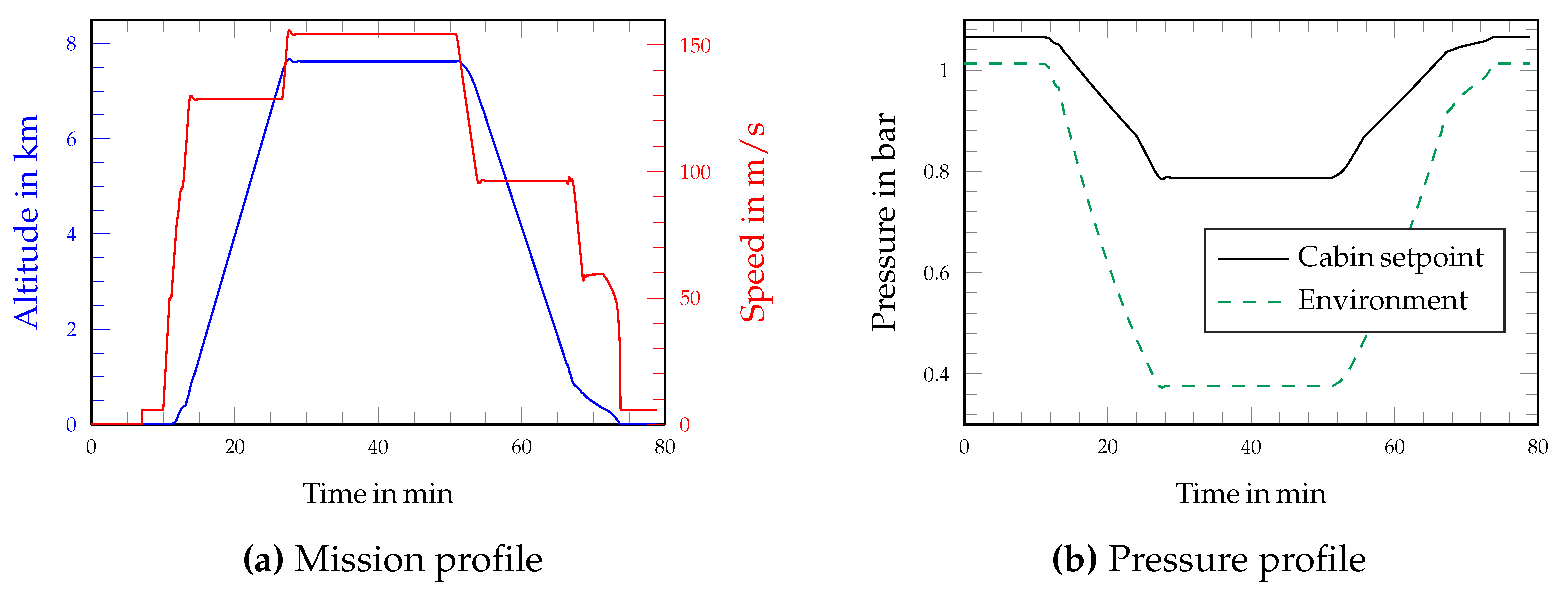
Furthermore, Figure 5a shows the mission profile under consideration, i.e., flight altitude and flight speed over time and Figure 5b shows the corresponding cabin pressure setpoint and environmental pressure. The mission takes 80 min and consists of boarding, taxiing, take-off, climb to 7620 m (25,000 ft), 24 min of cruising at M a = 0.5 ( 154 m / s ), descent, landing, and finally taxiing to the boarding gate.
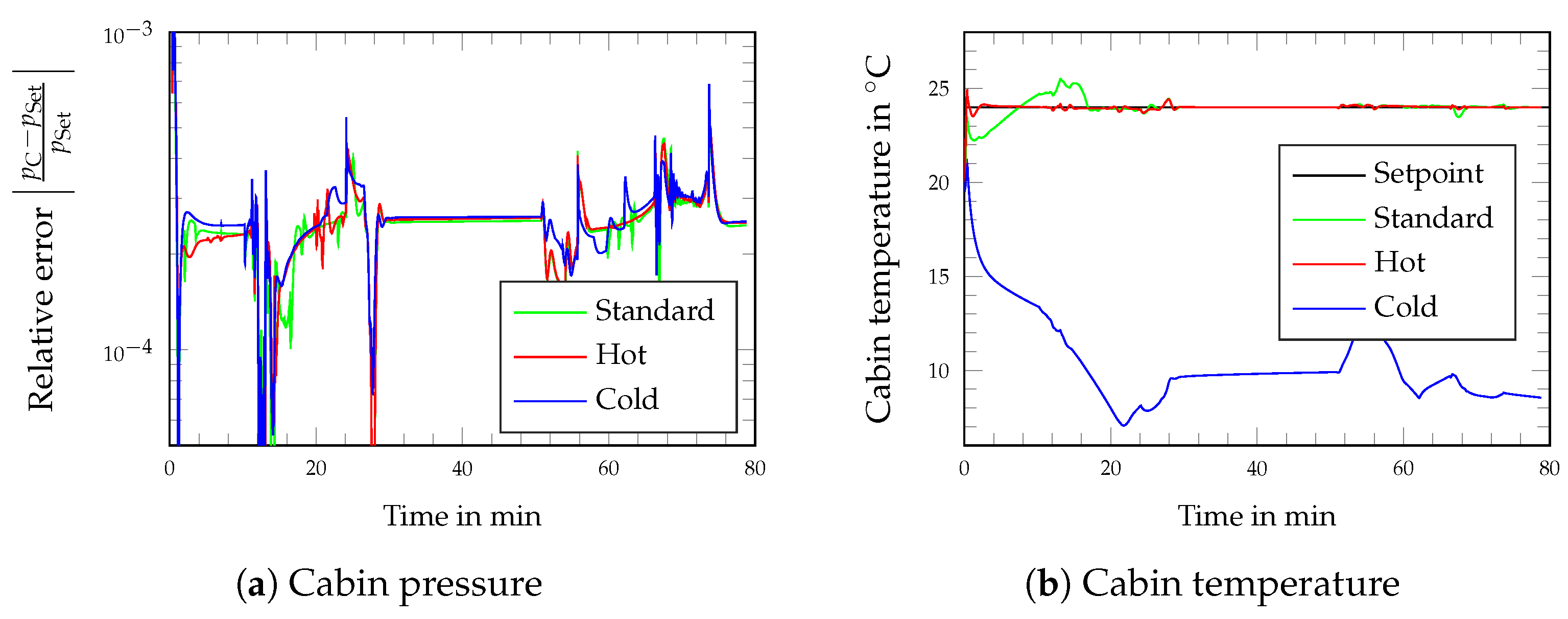
The simulation assumes 80 passengers (PAX), 2 pilots, and 2 crew members and the lumped volumes of the fuselage are initialized at standard pressure p = 1 atm and temperature T = 20 °C. Figure 6a shows the relative error of the cabin pressure p C with respect to the setpoint cabin pressure p Set . The cabin pressure control system can ensure that the relative error is smaller than 0.1 % under all ambient conditions. An exception is the initialization, where the setpoint p = 1 atm and the initial value p = 1.066 are different by definition. Figure 6b shows the cabin temperature for all environmental conditions. The cabin temperature setpoint of 24 °C can be achieved and maintained for standard and hot conditions, but not for cold conditions. This highlights the need for an additional heating system in the electrical ECS pack, which is not required for a conventional ECS pack, as the air from the engines has a temperature of about 200 °C.
Note that the base model itself is built from generic components of the TFS, which are based on frequently used correlations, but do not represent validated measurement data of specific components. Hence, the results of the base model can not be compared to real data, even if the components evolved over years of experience in different projects. Progressively, the generic components will be replaced by validated FMUs, provided within TheMa4HERA, improving the overall fidelity of the model and enabling virtual demonstration of the validated components at a system level.

4.2. FMU Integration

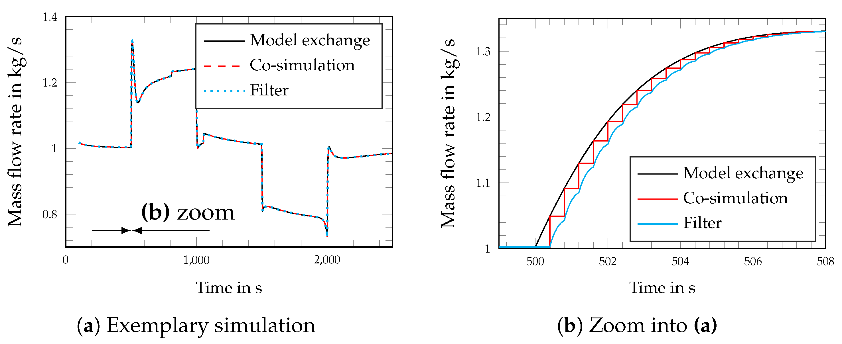
Figure 7 shows an exemplary simulation in which the outflow valve is integrated either as the model exchange FMU or as a co-simulation FMU using the novel control-like approach, as it is not possible to integrate the FMU with the standard Modelica adaptor approach. The overall results in Figure 7a are indistinguishable, but zooming in closer, one can recognise major differences.
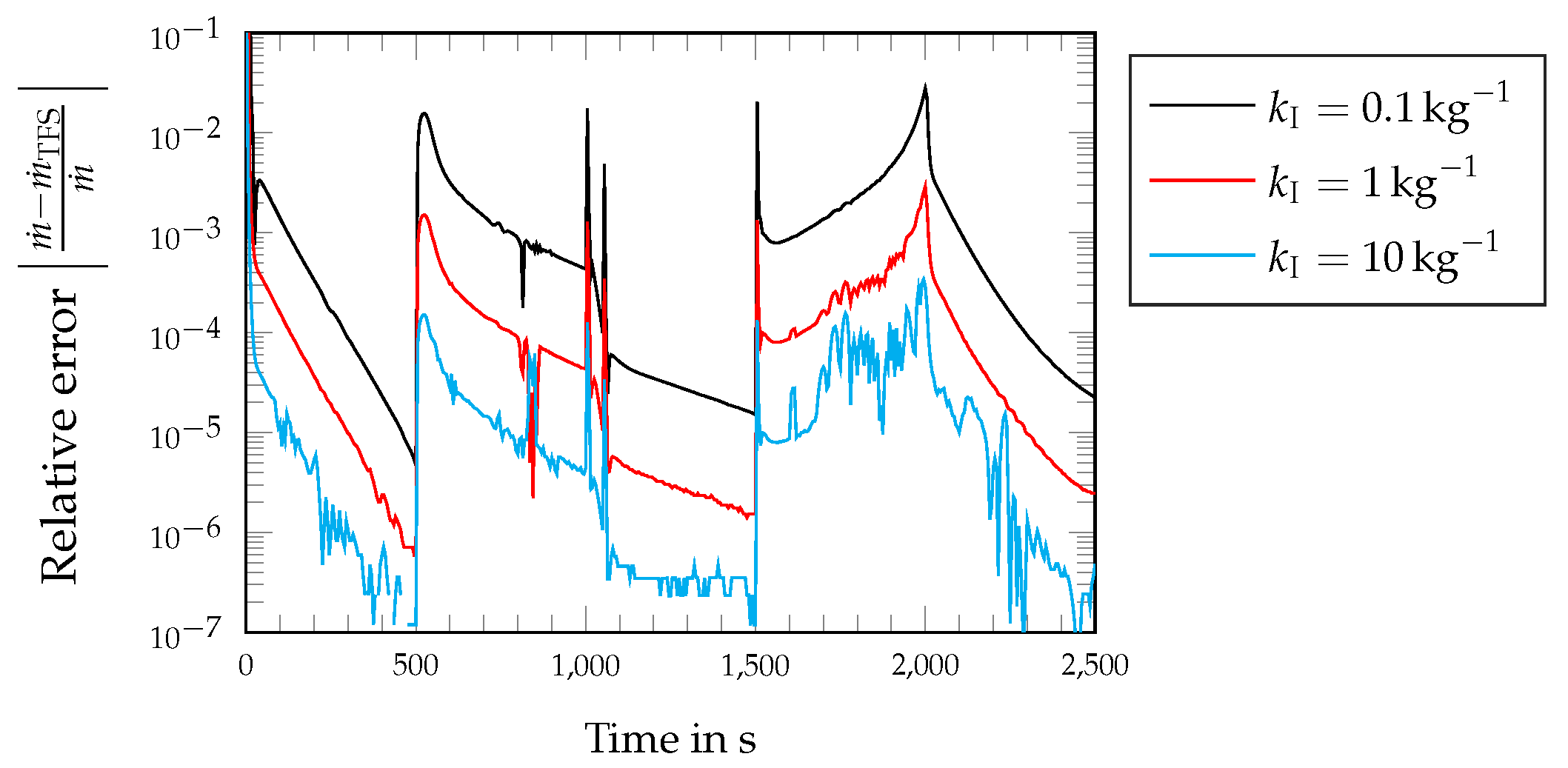
In the case of a co-simulation FMU, there exists a fixed communication time step size between the FMU and the solver of the overall simulation. At each communication time step, FMU receives inputs, calculates the outputs, and provides them at the next communication time step. This sampling-like approach is neither physically nor numerically favourable. If the step size is too small, the simulation becomes very slow, while a too large communication time step sizes can even lead to the overall simulation becoming unstable. A gate-to-gate mission simulation, which took around 5 min for the basic model, required around 10 min with model exchange FMU and several hours with co-simulation FMU. By using a first-order filter at the output of the co-simulation FMU to smooth the step signal, the simulation time was at least reduced to 1 h . However, based on the results, a strong recommendation is made for the use of model exchange FMUs, since the effect on simulation time is expected to be even more significant when integrating multiple FMUs. Figure 8 shows the absolute error in the mass flow rate | m ˙ m ˙ FMU | of the TFS base model in relation to its setpoint coming from the FMU.
As integrator gain k I = increases, the absolute error decreases approximately linearly, such that the error, except initialisation, is less than 3% for k I = 0.1 kg−1, less than 0.3% for k I = 1 kg−1 and less than 0.034% for k I = 10 kg−1. Compared to overall model uncertainties of possibly ±5%, the error introduced by the control approach is very likely negligible. Note, that too high gains make the system stiffer.

5. Discussion

This paper proposed a new control-like approach for the integration of FMUs in Modelica libraries. This approach keeps the computational robustness of the base model and minimises the simulation time. On one hand the approach can be interpreted as a numerical tool, designed to yield correct steady-state solution and minimize transient errors, and, on the other hand, the additional low pass filter can be interpreted as the inertia of the system. This approach avoids the design and use of adaptors, which pose many challenges for thermofluid models and would require FMUs to follow strict design rules to avoid algebraic loops and nonlinear equations, as the new approach decouples FMUs from the library components. In this regard, the coupling approach ensures that the robustness of the base library is not compromised by FMUs, keeping the overall simulation robust. It has been shown that the numerical error introduced by this approach can be directly influenced by the integrator gain, which can be adjusted to keep the error negligible alongside other uncertainties of the model, thereby avoiding a stiff system that would slow down the simulation too much. This new approach was necessary to integrate a validated model of an outflow valve into the base model of the digital twin, which otherwise could only be integrated if the structure of the TFS had been fundamentally changed, as the modeling approach of the FMU and the TFS did not match. As modelling approaches might often not be easily compatible, this approach might be equally beneficial in other cases of dynamic simulation of physical systems. The base model of the digital twin is built from generic components of the TFS, which are based on frequently used correlations but do not represent any existing components, the results cannot directly be validated against hardware demonstrations. However, this gap will be progressively closed by replacing the generic components with validated FMUs provided within TheMa4HERA, improving the overall fidelity of the model and enabling virtual demonstration once the improved models are validated. For the integration and simulation of multiple FMUs instead of just one as the next step, robustness and an easy-to-implement approach will be even more important to keep the simulation feasible. The trade-off between fidelity and simulation time will therefore directly impact the number of tests that can be performed with the digital twin.

Author Contributions

Conceptualization, R.G. and C.L.; methodology, R.G. and C.L.; software, R.G. and C.L.; validation, R.G. and C.L.; formal analysis, R.G. and C.L.; investigation, R.G. and C.L.; resources, R.G. and C.L.; data curation, R.G. and C.L.; writing—original draft preparation, R.G. and C.L.; writing—review and editing, R.G. and C.L.; visualization, R.G. and C.L.; supervision, R.G. and C.L.; project administration, R.G. and C.L.; funding acquisition, R.G. and C.L.; All authors have read and agreed to the published version of the manuscript.

Funding

This work was carried out as part of the European project TheMa4HERA. The project is supported by the Clean Aviation Joint Undertaking and its members. Funded by the European Union under Grant Agreement No. 101102008. Engproc 90 00012 i001

Institutional Review Board Statement

Not applicable.

Informed Consent Statement

Not applicable.

Data Availability Statement

Models and simulation results belong to the TheMa4HERA project, under Grant Agreement No.101102008 and cannot be shared without explicit consent of the consortium.

Conflicts of Interest

The authors declare no conflicts of interest. The funders had no role in the design of the study; in the collection, analyses, or interpretation of data; in the writing of the manuscript; or in the decision to publish the results.

Abbreviations

The following abbreviations are used in this manuscript:
ECSEnvironmental control systemFMIFunctional Mock-Up Interface
FMUFunctional Mock-Up UnitMSLModelica Standard Library
TFSThermofluid Stream LibraryTMSThermal management system
TheMa4HERAThermal management for hybrid electric regional aircraft

References

  1. CORDIS—EU Research Results—TheMa4HERA. Available online: https://cordis.europa.eu/project/id/101102008 (accessed on 15 November 2024).
  2. Asli, M.; König, P.; Sharma, D.; Pontika, E.; Huete, J.; Konda, K.R.; Mathiazhagan, A.; Xie, T.; Höschler, K.; Laskaridis, P. Thermal management challenges in hybrid-electric propulsion aircraft. Prog. Aerosp. Sci. 2024, 144, 100967. [Google Scholar] [CrossRef]
  3. Fritzson, P. Principles of Object-Oriented Modeling and Simulation with Modelica 3.3: A Cyber-Physical Approach, 2nd ed; John Wiley and Sons (Online): Hoboken, NJ, USA, 2014. [Google Scholar]
  4. Fritzson, P. The Openmodelica Environment for Building Digital Twins of Sustainable Cyber-Physical Systems. In Proceedings of the Winter Simulation Conference (WSC), Phoenix, AZ, USA, 12–15 December 2021; pp. 1–12. [Google Scholar] [CrossRef]
  5. Magargle, R.; Jonhson, L.; Mandloi, P.; Davoudabadi, P.; Kesarkar, O.; Krishnaswamy, S.; Batteh, J.; Pitchaikani, A. A Simulation-Based Digital Twin for Model-Driven Health Monitoring and Predictive Maintenance of an Automotive Braking System. In Proceedings of the 12th International Modelica Conference, Prague, Czech Republic, 15–17 May 2017. [Google Scholar]
  6. Zimmer, D.; Meißner, M.; Weber, N. The DLR ThermoFluid Stream Library. Electronics 2022, 11, 3790. [Google Scholar] [CrossRef]
  7. Zimmer, D. Robust object-oriented formulation of directed thermofluid stream networks. Math. Comput. Model. Dyn. Syst. 2020, 26, 204–233. [Google Scholar] [CrossRef]
  8. Bender, D. Exergy-Based Analysis of Aircraft Environmental Control Systems and Its Integration into Model-Based Design. Ph.D Dissertation, Technische Universität Berlin, Berlin, Germany, September 2018. Available online: https://elib.dlr.de/124010/ (accessed on 15 November 2024).
  9. Merzvinskas, M.; Bringhenti, C.; Tomita, J.T.; De Andrade, C.R. Air conditioning systems for aeronautical applications: A review. Aeronaut. J. 2020, 124, 499–532. [Google Scholar] [CrossRef]
  10. Sinnett, M. 787 no-bleed systems: Saving fuel and enhancing operational efficiencies. Aero Q. 2007, 18, 6–11. [Google Scholar]
  11. Blochwitz, T.; Otter, M.; Åkesson, J.; Arnold, M.; Clauss, C.; Elmqvist, H.; Friedrich, M.; Junghanns, A.; Mauss, J.; Neumerkel, D.; et al. Functional mockup interface 2.0: The standard for tool independent exchange of simulation models. In Proceedings of the 9th International Modelica Conference, Munich, Germany, 3–5 September 2012; pp. 173–184. [Google Scholar]
  12. Hirano, Y.; Shimada, S.; Teraoka, Y.; Seya, O.; Ohsumi, Y.; Murakami, S.; Hirono, T.; Sekisue, T. Initiatives for acausal model connection using FMI in JSAE (Society of Automotive Engineers of Japan). In Proceedings of the 11th International Modelica Conference, Versaille, France, 21–23 September 2015; pp. 795–801. [Google Scholar]
  13. Richter, C. Proposal of New Object-Oriented Equation-Based Model Libraries for Thermodynamic Systems. Doctoral Dissertation, Technische Universität Braunschweig, Braunschweig, Germany, 2008. [Google Scholar]
  14. Jorissen, F.; Reynders, G.; Baetens, R.; Picard, D.; Saelens, D.; Helsen, L. Implementation and verification of the IDEAS building energy simulation library. J. Build. Perform. Simul. 2018, 11, 669–688. [Google Scholar] [CrossRef]
  15. Wetter, M.; Fuchs, M.; Nouidui, T. Design Choices for Thermofluid Flow Components and Systems That Are Exported as Functional Mockup Units: Lawrence Berkeley National Laboratory. 2015. LBNL Report #: LBNL-1002826. Available online: https://escholarship.org/uc/item/67r3f6vm (accessed on 15 November 2024).
  16. Sielemann, M.; Casella, F.; Otter, M.; Clauß, C.; Eborn, J.; Mattsson, S.; Olsson, H. Robust Initialization of Differential-Algebraic Equations Using Homotopy. In Proceedings of the 8th International Modelica Conference, Dresden, Germany, 20–22 March 2011; pp. 75–85. [Google Scholar]
  17. Casella, F.; Sielemann, M.; Savoldelli, L. Steady-state initialization of object-oriented thermo-fluid models by homotopy methods. In Proceedings of the 8th International Modelica Conference, Dresden, Germany, 20–22 March 2011; pp. 86–96. [Google Scholar]
  18. Junglas, P.; Drente, P. Simulating a simple pneumatics network using the Modelica Fluid library. SNE Simul. Notes Eur. 2015, 25, 85–92. [Google Scholar] [CrossRef]
  19. Zimmer, D.; Giese, T.; Crespo, M.; Vial, S. Model Exchange in Industrial Practice. In Proceedings of the Greener Aviation Conference, Brussels, Belgium, 12–14 March 2014. [Google Scholar]
  20. Windholz, B.; Sporr, A.; Kling, S.; Lauermann, M.; Längauer, A.; Adler, B. Simulation towards demonstration: A Digital-Twin for developing control concepts of an industrial-scale Rotation Heat Pump. In Proceedings of the ECOS 2022, 35th International Conference on Efficiency, Cost, Optimization, Simulation and Environmental Impact of Energy Systems, Copenhagen, Denmark, 3–7 July 2022. [Google Scholar]
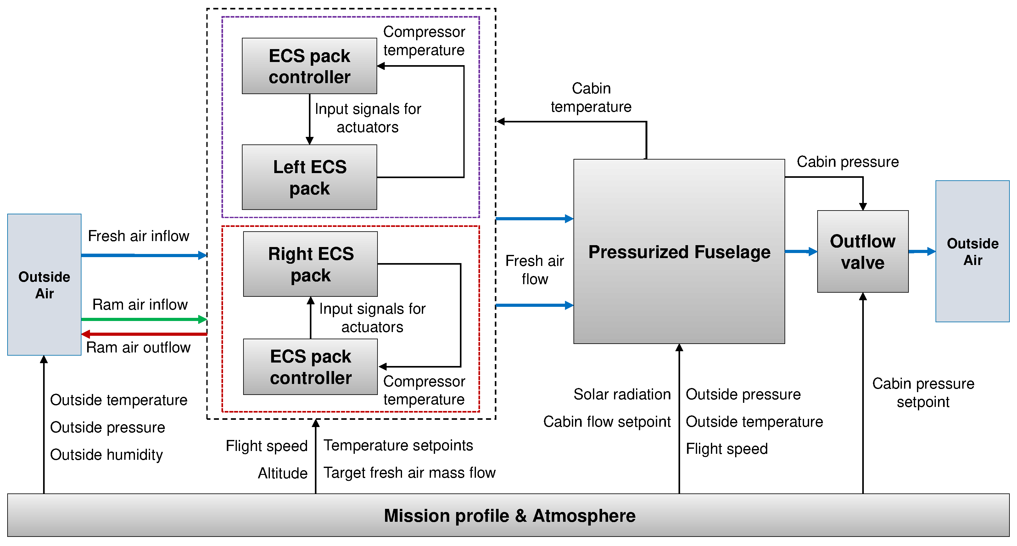
Figure 1. Schematic of the digital twin environmental control system architecture.
Engproc 90 00012 g001
Figure 2. Thermofluid stream model of an electrically driven bleedless bootstrap cycle.
Engproc 90 00012 g002
Figure 3. Implementation of Equation (1). Thick lines denote acausal connections, whereas normal lines denote causal signals. Note that the two different implementations of FMU (b,c) require two different adaptors. Considering also temperature T (or specific enthalpy h), mass fractions X , and effects like reverse flows (outlet to inlet), a large number of different adaptors would be necessary.
Engproc 90 00012 g003
Figure 4. Integrated valve: FMU is moved out of the loop, the library component is kept, and a controller enables the base model to mimic the FMU, whose output signal m ˙ FMU is treated as a setpoint.
Engproc 90 00012 g004
Figure 5. Gate-to-gate mission profile and pressure profile used in the digital twin.
Engproc 90 00012 g005
Figure 6. (a) Relative error of cabin pressure p C with respect to its setpoint p Set and (b) cabin temperature for a gate-to-gate mission simulation according to Figure 5, for standard, hot, and cold environmental conditions.
Engproc 90 00012 g006
Figure 7. Exemplary simulation of the outflow valve. (b) is a zoom at the first peak, when the cabin pressure is released, such that the mass flow rate through the outflow valve is increased.
Engproc 90 00012 g007
Figure 8. Relative error of mass flow rate | ( m ˙ m ˙ FMU ) / m ˙ | for an exemplary simulation of the outflow valve depending on the integrator gain k I .
Engproc 90 00012 g008
Disclaimer/Publisher’s Note: The statements, opinions and data contained in all publications are solely those of the individual author(s) and contributor(s) and not of MDPI and/or the editor(s). MDPI and/or the editor(s) disclaim responsibility for any injury to people or property resulting from any ideas, methods, instructions or products referred to in the content.