Article

Cartesian Aerial Manipulator with Compliant Arm

GRVC Robotics Labs, University of Seville, 41092 Sevilla, Spain
*
Author to whom correspondence should be addressed.
Appl. Sci. 2021, 11(3), 1001; https://doi.org/10.3390/app11031001
Submission received: 28 December 2020 / Revised: 16 January 2021 / Accepted: 18 January 2021 / Published: 22 January 2021
(This article belongs to the Special Issue Aerial Robotics for Inspection and Maintenance)

Abstract

:
This paper presents an aerial manipulation robot consisting of a hexa-rotor equipped with a 2-DOF (degree of freedom) Cartesian base (XY–axes) that supports a 1-DOF compliant joint arm that integrates a gripper and an elastic linear force sensor. The proposed kinematic configuration improves the positioning accuracy of the end effector with respect to robotic arms with revolute joints, where each coordinate of the Cartesian position depends on all the joint angles. The Cartesian base reduces the inertia of the manipulator and the energy consumption since it does not need to lift its own weight. Consequently, the required torque is lower and, thus, the weight of the actuators. The linear and angular deflection sensors of the arm allow the estimation, monitoring and control of the interaction wrenches exerted in two axes (XZ) at the end effector. The kinematic and dynamic models are derived and compared with respect to a revolute-joint arm, proposing a force-position control scheme for the aerial robot. A battery counterweight mechanism is also incorporated in the X–axis linear guide to partially compensate for the motion of the manipulator. Experimental results indoors and outdoors show the performance of the robot, including object grasping and retrieval, contact force control, and force monitoring in grabbing situations.

1. Introduction

1.1. Aerial Manipulation

Aerial manipulation robots (drones equipped with robotic arms) are extending the potential applications of multirotor platforms, allowing the realization of tasks involving the manipulation of objects and tools in flight, as well as interaction with the environment with a certain level of dexterity and control capability. The development of this technology is motivated by interest in reducing the time, cost and risk for human workers associated with the realization of certain tasks in high altitude or difficult access workspaces such as power lines [1,2], chemical plants [3], oil and gas refineries [4], and other infrastructures [5,6]. Recent works in this field have demonstrated the possibility to conduct operations such as object grasping [7,8,9], valve turning [10], sensor installation and retrieval [2,11], contact-based inspection [3,12,13], insulation of cracks and leaks [14], or the realization of other tasks with grippers and other tools [15,16]. Several prototypes and morphologies of manipulators have been specifically developed for their integration in multi-rotors, including multi-joint arms [17,18], dual arm systems [7,10], linear actuators [11], delta manipulators [14], compliant joint arms [2,19,20], long reach aerial manipulators [2,21], or three-arm manipulators used for object grasping and as reconfigurable landing gear [22].
Compliance, either mechanical [7,19,20,21,22,23] or at control level [11,24,25,26], is a highly desirable feature for an aerial manipulation robot operating in contact with the environment since the stability of the aerial platform may be compromised due to the interaction wrenches exerted on flight [24,25,27]. The design and development of compliant manipulators aim to increase safety by exploiting the energy storage capacity and passivity properties of springs [7,19,26] and elastomers [23] while protecting the aerial robot against impacts and overloads [23]. Unlike most industrial manipulators that use expensive force-torque sensors in the joints or in the end effector, the servo actuators (Herkulex, Dynamixel) typically employed for building lightweight robotic arms for aerial manipulation do not provide a direct measurement of the torque; or this is based on the current, so its accuracy is low due to the friction of the gearbox. This has motivated the development of methods for estimating and controlling the forces and torques from the measurement of the deflection in the elastic element, either at joint level [7,19] or in the Cartesian space [26]. Despite the evident benefits of mechanical compliance during the physical interactions of the aerial robot while flying, the main drawback of these mechanisms is the reduction in position accuracy due to the deflection of the joints [19] or links [2], a consequence of the second order dynamics associated with the mass-spring-damper system [26]. As a result, the realization of tasks requiring accurate positioning tends to become more difficult.

1.2. Positioning Accuracy

Positioning accuracy is one of the most relevant and challenging requirements for an aerial manipulator operating on flight since it determines the reliability and success rate in the realization of tasks like grasping [7] or the installation of devices on power lines [1,26], especially outdoors where Vicon or OptiTrack systems are not available, whereas sensors like 3D laser scanners [28] and vision-based systems [29] are more suited. This feature is directly related to the performance of the multirotor position controller [30,31], affected by the endogenous and exogenous wrenches exerted through the manipulator [25,27]. On the one hand, tilted-rotor hexa-rotors, also known as fully actuated aerial platforms [32,33], allow the translation of the platform as well as the application of wrenches [34,35] without changing the orientation, which contributes to increasing the accuracy in the realization of manipulation tasks compared to coplanar multi-rotors. On the other hand, the error propagation at the end effector is closely related with the kinematic configuration and the physical construction of the manipulator. This is, in most cases, a multi-link arm [7,8,17,18,24] with revolute joints. However, this configuration present two main drawbacks: (1) the joint limits (especially in the elbow joint) constraint or reduce the effective reach and workspace of the arm, (2) a significant amount of torque and energy is needed to lift the weight of the manipulator itself (forearm-upper arm configuration), requiring high torque actuators that tend to increase the weight. Alternatively, other works propose the use of simple manipulators [3,5,11,14,15] in order to reduce the weight, at expenses of reducing the reach and dexterity.

1.3. Contribution of This Work

The main contribution of this paper is the design, development and experimental validation of a new morphology of aerial manipulation robot consisting of a hexa-rotor platform integrating a 2-DOF (degree of freedom) Cartesian base (XY–axes) that carries a 1-DOF compliant joint arm equipped with a gripper and a deflection-based force-torque sensor. Figure 1 shows a picture of the prototype. The proposed morphology is intended to improve the positioning accuracy of the end effector while reducing the inertia, torque and weight of the actuators, since the Cartesian base supports most of the weight of the robotic manipulator (0.85 kg weight, 1 m reach, and 10 cm/s speed). The elastic deflection sensors integrated in the compliant joint and in the fore-arm link are used to estimate and monitor the force (XZ–axes) and torque (pitch) exerted by the manipulator over the aerial platform. This allows the realization of a number of tasks such as sensor installation with contact force control, force monitoring in grabbing situations, or object grasping and retrieval. The kinematic and dynamic models of the aerial manipulator are derived, while analyzing in more detail the error propagation at the end effector from the Jacobian, comparing the proposed morphology with respect to that of a revolute-joint arm in terms of positioning accuracy, reach, and workspace. This paper also proposes a force-position control scheme for the aerial robot that takes into account the wrench estimation provided by the arm. Experimental results conducted in test-bench as well as indoor/outdoor flight tests validate the functionalities and capabilities of the developed Cartesian aerial robot.
The rest of the paper is organized as follows. Section 2 presents the motivation for and describes the prototype of a Cartesian aerial manipulator with compliant joint arm. Section 3 presents the kinematic and dynamic models of the aerial robot, analyzing and comparing the features of the Cartesian manipulator with respect to a revolute-joint arm. Section 4 covers the control of the aerial robot, the experimental results are shown in Section 5, and the conclusions in Section 6.

2. System Description

2.1. Motivation

The Cartesian manipulator aims to avoid three inconveniences of the human-like robotic arms developed in our previous work [7,19]. First of all, several manipulation tasks like grasping or peg-in-hole are defined in the Cartesian space rather than in the joint space, so it is more convenient that the mapping between both spaces is straightforward in order to improve the positioning accuracy. According to the forward kinematic model, the XYZ position of the end effector depends simultaneously on the rotation angle of the three [19] or four [7] joints of the manipulator (shoulder and elbow). Therefore, the joint position errors, as well as errors associated with the manufacturing and assembly of the arm (clearance, misalignment), will be propagated to the three Cartesian coordinates of the end effector. Additionally, the mechanical deflection of the joints in a compliant arm [7] may cause deviations of several centimeters in the position of the end effector with respect to an equivalent stiff-joint arm. In a Cartesian manipulator, instead, the position of the end effector on each axis is controlled with its own actuator independently from the other joints, so the position errors are decoupled and the trajectory control in the task space is simplified.
Secondly, the effective reach of a human-like manipulator (~50 cm reach) is in practice relatively small, around 30 cm, taking into account that the nominal operation position of the arm is typically an L-shaped configuration (forearm lifted 90°) and due to the limit in the rotation angle of the elbow joint. Note that humans extend the reach of the hands with the torso and legs, whereas in an aerial manipulator the motion of the arms is usually constrained by the landing gear and the perimeter of the propellers. In this sense, the Cartesian base avoids dead-zones in its workspace due to joint limits, allowing access to points close to the multirotor base, which can be useful, for example, in object retrieval and storage. Finally, a two link manipulator in the upper arm-forearm morphology typically requires a significant amount of torque and energy to lift its own weight, whereas in the developed prototype the Cartesian manipulator only has to compensate for the inertia and friction of the carriage, reducing in this way the required torque of the actuators, and thus, their weight. Not only that, but the linear guide also isolates the actuators from impacts and loads, avoiding the design of bearing-based protection mechanisms, as in [7].
The Cartesian manipulator shown in Figure 1 implements a Prismatic-Prismatic-Revolute (PPR) configuration, introducing a revolute joint attached at the Cartesian base, since the landing gear and central body of the hexa-rotor platform do not allow the placement of a linear actuator in the vertical axis, and because this configuration extends the reach of the end effector in the X–axis (forward direction). No additional degrees of freedom are considered for end effector positioning due to the convenience of reducing the weight, complexity and size of the manipulator, and because the capabilities of the robot can be extended with the additional degrees of freedom provided by the aerial platform [13,32].

2.2. Mechanical Design

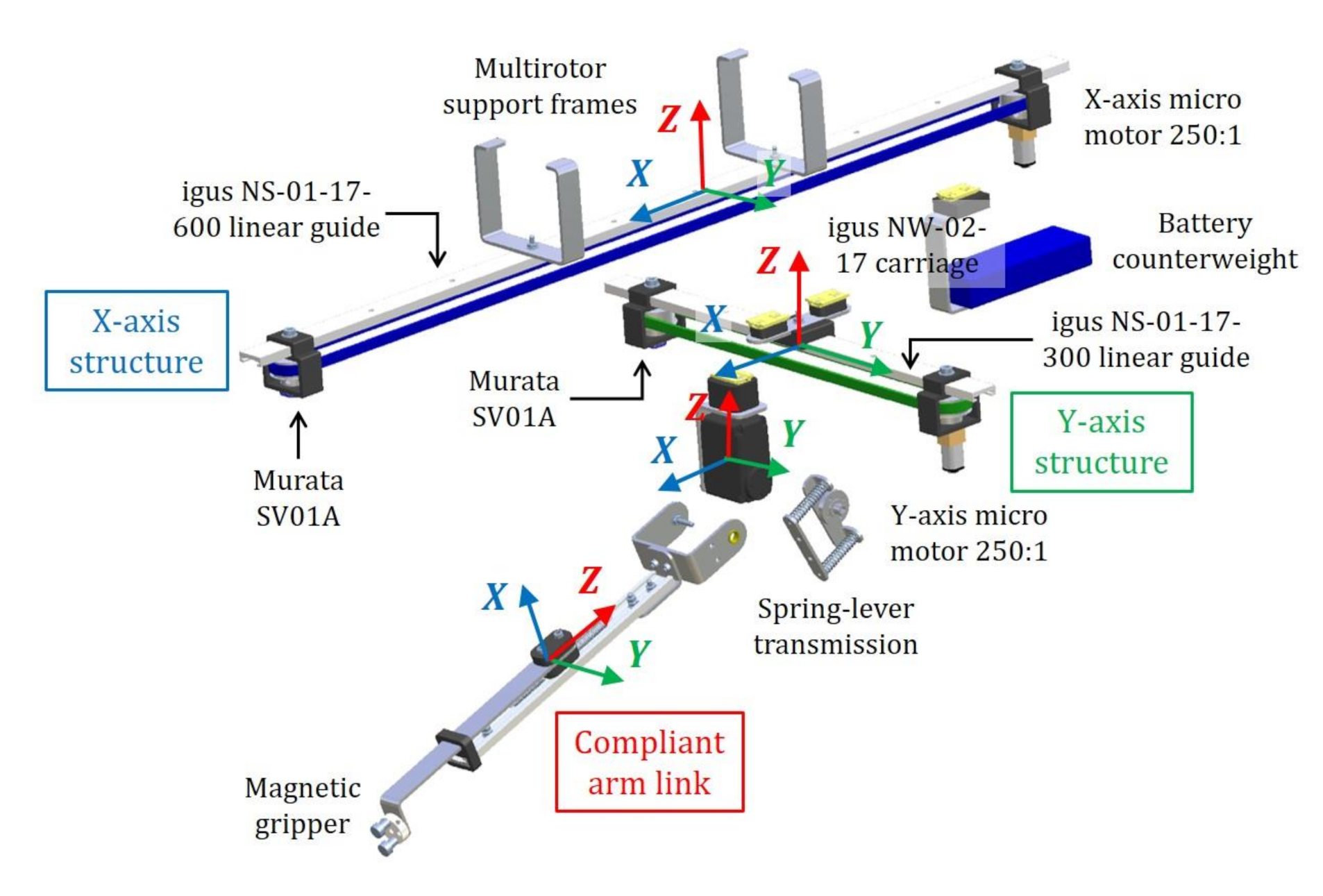
The Cartesian aerial manipulator shown in Figure 1 consists of two systems. The aerial platform is built from a Banggood S550 hexa-rotor (similar to the DJI F550) that integrates the DJI 2312E brushless motors with 9 × 4.5 inch propellers, and DJI 430 LITE electronic speed controllers (ESC). The onboard controller comprises a Pixhawk autopilot and a Raspberry Pi model 3B+ that implements the software architecture described in the next subsection. The Cartesian manipulator is divided into the five parts identified in Figure 2: X–axis linear guide (base), Y–axis linear guide, servo actuator, compliant arm and battery counterweight mechanism. The mechanical specifications of the manipulator are indicated in Table 1, representing in Table 2 the mass and inertia parameters obtained from the 3D model.
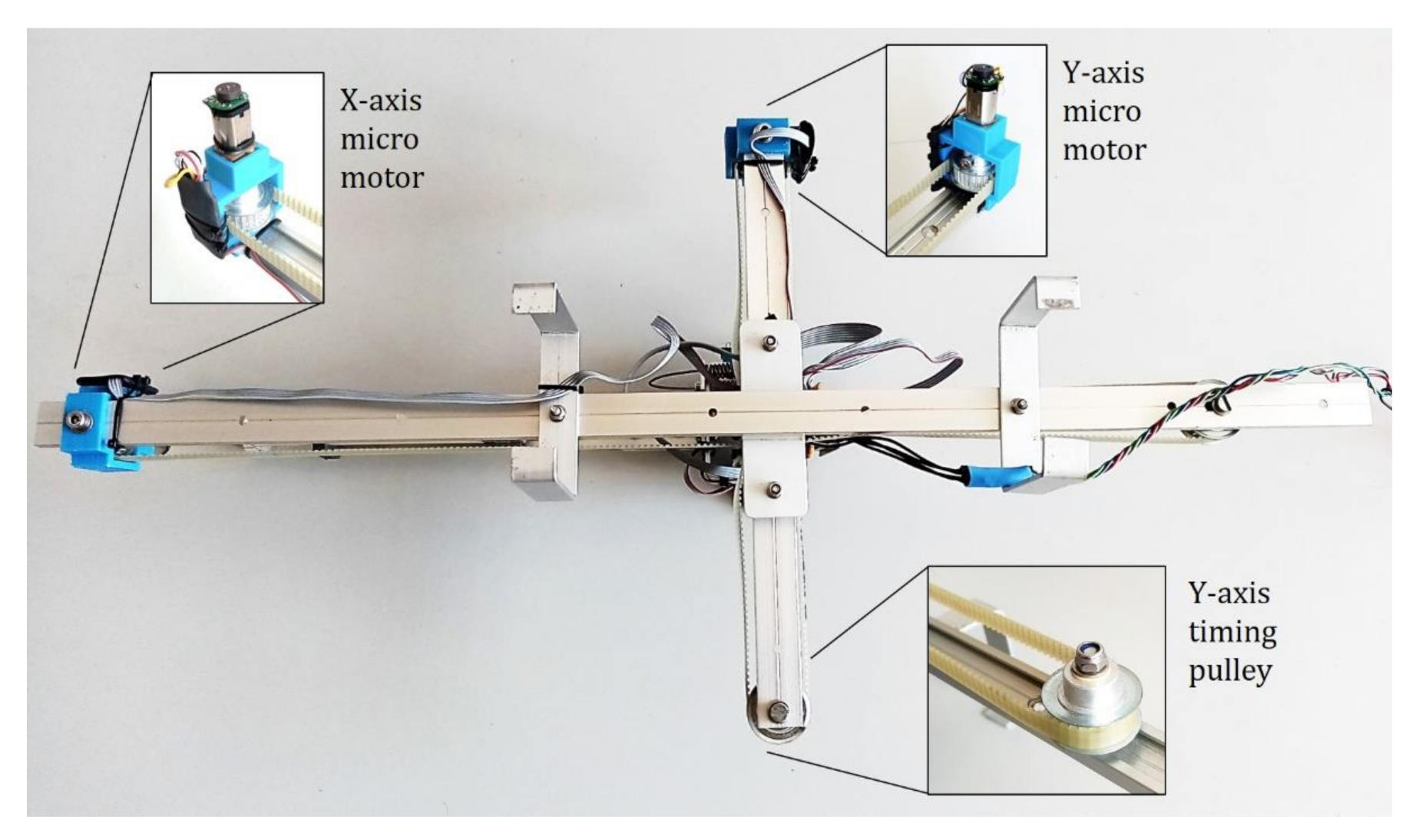
The 2-DOF Cartesian base is built from the igus® NS-01-17-600 (X–axis) and NS-01-17-300 (Y–axis) linear guides, using three NW-02-17 carriages to support the mobile parts. Two 22 mm Ø timing pulleys are placed at the tip of both linear guides to transmit the motion of the Pololu micro metal gear motors (10 g weight, 250:1 reduction ratio, 2.7 kg·cm stall torque) to the timing belts, measuring the rotation angle with a Murata SV01A potentiometer and with the magnetic encoder of the micro-motors. The linear displacement of the Cartesian base relative to an initial position is obtained from the rotation angle and the number of turns given by the encoder (6 pulses per revolution at the micro motor shaft, 1500 pulses per turn at the output shaft of the gearbox). Figure 3 illustrates the timing pulley-belt actuator in the X and Y linear guides. The battery counterweight is supported by a C-shaped aluminum frame that can slide along the X–axis linear guide and move in synchronization with the Y–axis structure, but in the opposite direction when it is attached to the X–axis timing belt (see Section 5.2).
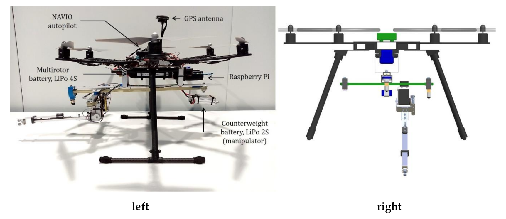
The integration of the Cartesian manipulator in the hexa-rotor platform and the battery counter-weight mechanism are shown in Figure 4. The X–axis linear guide is supported by the carbon fiber tubes attached to the multirotor base through the two U-shaped aluminum frames identified in Figure 2. As can be seen in the front view of Figure 4, the legs of the landing gear should be separated to avoid collision of the Y–axis linear guide. However, this additional separation is not needed if the battery counter-weight mechanism is enabled. As depicted in Figure 4, this mechanism consists of a C–shaped aluminum frame that supports the 2S LiPo battery and is actuated by the X–axis timing pulley, but in the opposite direction to the Y–axis linear guide. Since both structures share the same linear guide, the effective range is reduced by half. The counterweight mechanism can be set to a fixed position by simply removing the zip tie that connects the timing belt with the linear carriage.
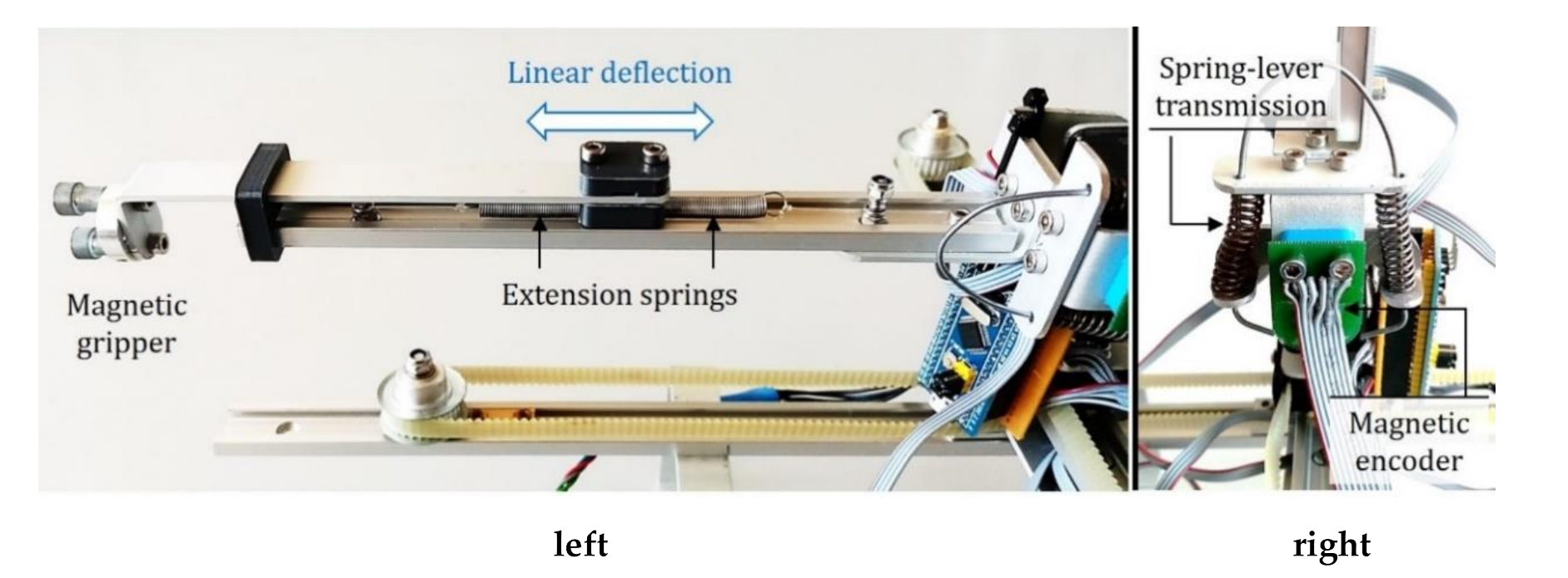
The compliant arm depicted in Figure 5 employs a Herkulex DRS-0101 servo and a spring-lever transmission mechanism (1.4 Nm/rad stiffness) that allows the estimation and control of the torque from the deflection measurement [19], integrating an AS5048 magnetic encoder to obtain the deflection angle at 500 Hz with 0.2° accuracy. The estimator described in Section 4.2 employs this signal for collision detection and controls the torque/force/impedance [26] exerted at the end effector. The link of the arm consists of a NS–01–17–200 linear guide and a NW–02–17 carriage that supports the displacement of the end effector (± 30 mm range), using a pair of extension springs (3.2 N/mm stiffness) and a linear potentiometer to estimate the pushing/pulling forces in the XZ–axes in grabbing conditions, as will be explained in Section 4.2.
The end effector of the arm can be reconfigured according to the intended task and type of object to be manipulated. This can be a simple hook to retrieve a device with handles, a magnetic gripper for catching ferromagnetic objects as hand tools, or a servo-gripper for grabbing objects of different shapes.
As indicated in the previous subsection, one of the main benefits of the Cartesian morphology with respect to the human-like dual arm systems developed in our previous work [7,26] is that the manipulator wastes lesser energy in lifting its own weight or reaching any point in its workspace, as the displacement of the end effector along the XY–axes is supported by the linear guide system. Note that in a forearm-upper arm configuration, the shoulder actuators must lift a 50 cm length frame structure, including the servo actuators placed in the links. Thus, the proposed solution is more energy efficient in this sense.
Finally, it is necessary to remark that the purpose of the Cartesian manipulator and the compliant arm is to provide a certain level of dexterity (3–DOFs) and sense capability ( F x , F z , τ θ ) to the aerial platform, sufficient to implement a number of functionalities and tasks without unnecessarily increasing the weight with additional sensors or actuators.

2.3. Hardware Architecture

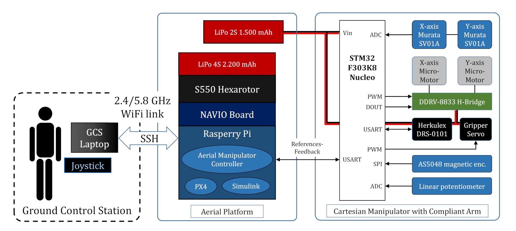
The components and architecture of the Cartesian aerial manipulator are represented in Figure 6. The aerial platform consists of the S550 hexa-rotor integrating the NAVIO autopilot and a Raspberry Pi 3B+ board running the PX4 firmware [36] as well as the control program of the manipulator, developed in C/C++. This program is built around the Task Manager class [2], which implements the different functionalities used in the experiments: go to rest position, go to operation position, teleoperation, force control and monitoring, and Cartesian base calibration. The manipulator is interfaced through a USB–to–USART (Universal Synchronous-Asynchronous Receiver Transmitter) device connecting the Raspberry Pi board with the STM32F303K8 Nucleo microcontroller that takes care of the low level control of the XY–axes’ micro motors and reads the measurements from the three sensors:
  • The two potentiometers used to estimate the displacement of the linear base.
  • The magnetic encoder attached to the servo that measures the joint deflection.
  • The linear potentiometer in the link used to estimate the pushing/pulling force.
The microcontroller generates as output the PWM (Pulse Width Modulation) signals taken as input by the DRV 8833 dual H-bridge that controls the micro motors (Section 4.1), providing another PWM signal to control a gripper servo. The Herkulex servo of the compliant joint is controlled in position through a dedicated USART interface [7,26]. The control references generated by the Task Manager and the feedback measurements collected by the microcontroller are sent at 100 Hz through the USART as data packets codified as C-type data structures.
The Cartesian aerial manipulator is operated from the Ground Control Station (GCS) through a wireless link, typically a Wi–Fi network, that supports the SSH (Secure Shell) session used to launch and manage remotely the aerial manipulator control programs. The commands introduced by the operator to select the particular task to be executed or to tele-operate the manipulator using a joystick are sent as C–type data packets through UDP (User Datagram Protocol) sockets.

3. Modelling

3.1. Kinematic Model

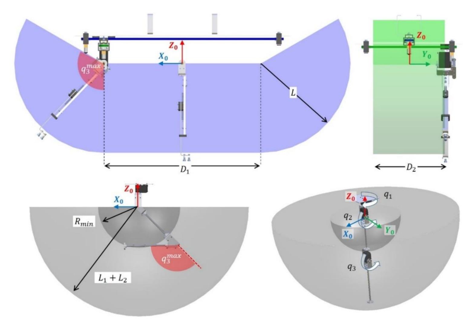
In the definition of an aerial manipulation task, three reference frames can be identified: the Earth fixed frame E (inertial), the multirotor base frame B , and the manipulator base frame 0 . The position and orientation of the multirotor, r E B = x , y , z T and η E B = ϕ , θ , ψ T , are referred to the Earth fixed frame, whereas the position of the tool center point (TCP) of the manipulator, r 0 T C P = x T C P , y T C P , z T C P   T , is expressed in 0 for convenience, considering that the onboard perception system usually gives the reference positions in the local axes. Figure 7 depicts the reference frames, position vectors and the joint variables in the Cartesian aerial manipulator. Here d 1 and d 2 denote the displacement of the Cartesian base along the X 0 Y 0 axes, respectively, q 3 is the rotation angle of the joint in the pitch angle, whereas D 1 , D 2 and L are the corresponding link lengths.
The position of the tool center point referred to 0 can be computed easily from the joint variables applying the forward kinematic model F K :   3 3 :
r 0 T C P = x T C P y T C P z T C P = F K d 1 d 2 q 3 = d 1 + L · sin q 3 d 2 L · cos q 3
Note that x T C P depends on two joint variables ( d 1 and q 3 ), although q 3 is determined by z T C P . The inverse kinematic model, I K :   3 3 , provides two analytical solutions for q 3 if x T C P < D 1 / 2 , and only one solution if x T C P D 1 / 2 . The double solution is determined by the sign of q 3 , and indicates the pointing direction of the link, either forwards or backwards:
d 1 d 2 q 3 = I K x T C P y T C P z T C P = x T C P L · sin α y T C P ± α
where angle α is defined in the following way:
α = cos 1 z T C P L

3.2. Positioning Accuracy and Workspace

It is interesting to compare the workspace, joint limits and position errors of the proposed Cartesian manipulator with compliant joint arm with respect to other kinematic configurations, like the 3–DOF robotic arm described in [19], where the TCP position is given by:
r 0 T C P * = r q 2 ,   q 3 · cos q 1 r q 2 ,   q 3 · sin q 1 L 1 cos q 2 + L 2 cos q 2 + q 3
Here L 1 and L 2 are the upper arm and forearm link lengths, respectively, and:
r q 2 ,   q 3 = L 1 sin q 2 + L 2 sin q 2 + q 3
As stated in the introduction and in Section 2.1, the Cartesian base reduces the propagation of positioning errors in the TCP due to angular deviations (joint deflection) or manufacturing errors (misalignments, clearance). This can be quantitatively evaluated through the Jacobian matrix:
ε T C P = J q · ε q
where ε T C P is the position deviation of the TCP in the XYZ axes due to a variation in the vector of joint variables ε q , which depends on the Jacobian of the arm particularized to the nominal pose, J q . Although it is omitted for space reasons, the Jacobian of the manipulator described by Equation (4) introduces coupled terms in the XYZ axes, i.e., each of the Cartesian coordinates depends on the three joint variables simultaneously, whereas in the kinematic configuration considered in this paper, the Jacobian matrix is significantly simplified, resulting in the following expression.
As can be seen, the positioning accuracy in the X–axis depends on the accuracy of the X–axis actuator and on the compliant joint, whereas the accuracy on the YZ axes dep
ε T C P = ε Y ε Y ε Z = 1 0 L · cos q 3 0 1 0 0 0 L · sin q 3 · ε d 1 ε d 2 ε q 3 = ε d 1 + L · cos q 3 · ε q 3 ε d 2 L · sin q 3 · ε q 3
ends on the accuracy of the d 2 and q 3 coordinates.
The volume of operation of the Cartesian manipulator is a parallelepiped of length D 1 = 0.5   m , depth D 2 = 0.2   m , and height L = 0.2   m , with two additional circular sections generated by the revolution of the compliant joint with maximum rotation. q 3 m a x is around 120 ° :
V = D 1 D 2 L + D 2 L 2 q 3 m a x = 0.037   m 3
whereas the volume of operation of a 3–DOF robotic arm corresponding to a hollow semi-sphere with upper arm link length L 1 = 0.2   m and forearm link length L 2 = 0.2   m is given by:
V * = 4 3 π L 1 + L 2 3 R m i n 3 = 0.234   m 3
This is represented graphically in Figure 8, and compared with respect to the workspace of the 3–DOF manipulator described in [19]. The hollow area is determined by the maximum rotation angle of the elbow joint, q 3 m a x , defining a minimum radius R m i n from the origin of the manipulator frame to the end effector. Although the difference is significant, the dexterity and performance of configurations with revolute joints are typically reduced when integrated in multirotor platforms due to the motion constraints associated with the landing gear and the effect of the kinematic singularities when the arm tends to be stretched. The effective workspace of the Cartesian prototype described here can be extended by exploiting the rotation of the multirotor in the yaw angle, equal to V = 0.13   m 3 for a full rotation. The combination of this morphology with tilted or fully actuated platforms like [32,33,34] is especially convenient in applications related to object retrieval and storage in order to extend the workspace of the aerial robot while providing a high positioning accuracy.

3.3. Dynamic Model

The equations of the dynamic model of the Cartesian aerial manipulator with compliant arm can be derived following the Euler-Lagrange formulation based on the Lagrangian and the generalized equation of the forces and torques:
d d t L ξ ˙ L ξ = Γ + Γ e x t   ;   L = K V
Here L is the Lagrangian, which is the difference between the kinetic and potential energies, K and V , respectively, ξ is the vector of generalized coordinates, whereas Γ and Γ e x t are the vectors of endogenous and exogenous (external) generalized forces, defined as follows.
ξ = E r B T E η B T d 1 d 2 q 3 θ 3 l 4 T 11
Γ = F B T τ B T F 1 F 2 τ 3 τ m , 3 F 4 T 11
where r E B = x , y , z T and η E B = ϕ , θ , ψ T represent the position and orientation of the aerial platform in the Earth fixed frame, d 1 , d 2 , and q 3 are the joint variables defined earlier, and l 4 is the linear elongation of the end effector. The forces and torques acting over the hexa-rotor are denoted by F B and τ B , whereas F 1 and F 2 are the force exerted by the Cartesian manipulator in the X and Y axes, respectively, τ 3 is the torque applied over the compliant joint, and F 4 is the force exerted or supported in the direction of the arm link.
The kinetic energy is the sum of two terms corresponding to the aerial platform, considered as a rigid solid, and the masses of the manipulator:
K = 1 2 m A P r ˙ E B 2 + 1 2 ω E B T I A P ω E B + 1 2 i = 1 4 m i r ˙ E i 2 + ω E i T I i ω E i
where m A P and I A P are the mass and inertia tensor of the aerial platform (including the X–axis support structure), m i and I i are the mass and inertia of the i -th link of the manipulator (Y–axis linear structure, servo structure, arm link and forearm, as indicated in Figure 2 and Table 2), r ˙ E B and ω E B are the translational and rotational speed of the aerial platform, whereas r ˙ E i and ω E i are the speed of the i -th link of the manipulator.
The potential energy includes the gravity potential and elastic potential of the compliant joints:
V = g e Z T m A P r E B + i = 1 4 m i r E i + 1 2 k 3 θ 3 q 3 2 + 1 2 K S l 2
Here g is the gravity constant, e Z T = 0 ,   0 ,   1 is the Z–axis unit vector, k 3 is the torsional stiffness of the compliant joint, and K S is the stiffness of the extension springs that support the end effector, as shown in Figure 5. Applying the Lagrangian in Equation (10) over the kinetic and potential energies given by Equations (13) and (14), the usual compact matrix form is derived, given by:
M ξ ξ ¨ + C ξ , ξ ˙ + G ξ + K ξ = Γ + Γ e x t
where M 11 × 11 is the generalized inertia matrix, C 11 represents the centrifugal and Coriolis terms, G 11 corresponds to the gravity wrenches, and K 11 are the elastic potential terms. It is worth noting that, since the analytical expression of the kinematics of the Cartesian manipulator is simpler compared to a revolute joint arm due to the reduction in sine/cosine terms and the decoupling of the Cartesian coordinates, the complexity of the dynamic model is reduced, and consequently so is the computational time, facilitating real-time implementation.

4. Estimation and Control

4.1. Cartesian Base Control

The Cartesian manipulator described in Section 2.2 is built with DC micro-motors controlled at low level through a PWM signal (1 kHz frequency) generated by the microcontroller board. The motion of the linear guide system depicted in Figure 3 can be modelled as follows:
m i d ¨ i + f i d ˙ i = r i · p w m i ;   i = 1 ,   2
where m i is the displaced mass, f i is the friction coefficient of the linear carriage, p w m i 1 ,   1 represents the mean current injected to the motor relative to the stall current, whereas r i is a constant that depends on the motor current-torque constant and the radius of the timing pulley.
Two control modes are implemented on the microcontroller. On the one hand, the open-loop velocity control consists of directly applying the PWM reference provided by the higher level controller. According to Equation (16), if the acceleration term is neglected, then the linear velocity can be regulated directly through the PWM signal. On the other hand, a PI position controller executed at 100 Hz is used for moving the Cartesian base at desired absolute positions:
p w m i r e f = s i g n e d i · P W M i m a x i f   e d i e d i t h k P i · e d i + k I i · e d i d t i f   e d i < e d i t h
Here e d i = d i , r e f d i is the position error of the i -th Cartesian coordinate, P W M i m a x 0 , 1 is the maximum PWM of the micro motor ( P W M i m a x < 0.8 to prevent damaging the motor winding when it is stalled), whereas k P i and k I i are the proportional and integral gains. To avoid the discontinuity of the control signal, it is imposed that k P i · e d i t h = P W M i m a x . The integral term is reset when e d i e d i t h to prevent the saturation of the controller due to the wind-up effect.

4.2. Force-Torque Estimation with Compliant Arm

The linear and angular deflection sensors integrated in the compliant arm allow the estimation of the force and torque exerted on the manipulator in the corresponding directions, as represented in Figure 7. On the one hand, the spring-lever transmission mechanism introduced in the servo joint allows the estimation and control of the torque from the deflection measurement [7,19]. If k 3 and d 3 denote the joint stiffness and damping, the torque delivered by the motor can be estimated as follows:
τ m , 3 = k 3 Δ θ 3 + d 3 Δ θ ˙ 3
This torque is spent to compensate three terms: gravity, output link inertia, and the torque due to external forces:
τ m , 3 = J 3 q ¨ 3 + m 3 g l 3 sin q 3 + F e x t sin β L
Here m 3 and J 3 are the mass and inertia of the output link, l 3 is the distance from the rotation axis to the center of mass, and F e x t is the external force acting over the tool center point at distance L with an angle β . The transmitted torque can be controlled through the servo position reference [19]:
θ 3 r e f = θ 3 + k P 3 τ e , 3 + k I 3 τ e , 3 d t
where θ 3 is the current servo position, τ e , 3 = τ 3 r e f τ m , 3 is the torque error, and k P 3 and k I 3 are the gains in PI control. This controller will be applied in the experiment shown in Section 5.4. On the other hand, the force acting along the direction of the arm link is estimated from the elongation of the extension springs (see Figure 5), measured with a linear potentiometer:
F 4 = K 4 Δ l 4
where K 4 is the spring stiffness and Δ l 4 is the elongation. The experiment described in Section 5.3 (force monitoring in grabbing situations) exploits this estimation to detect over-loads and release the gripper in order to prevent crashes. The torque exerted by the compliant joint and the force along the link are supported by the thrust generated by the multirotor. These wrenches are depicted in Figure 7. However, note that the arm does not provide an estimation of the Y–axis wrenches.

4.3. Cartesian Aerial Manipulator Control Scheme

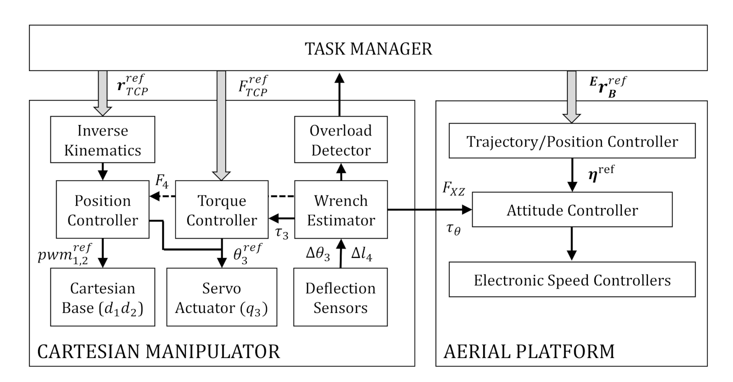
The control scheme of the Cartesian aerial manipulator is shown in Figure 9. The Task Manager [2,7] is the high-level functional block that implements the functionalities of the robot, generating the appropriate control references for the manipulator and the aerial platform, relying on the low level controllers of the Cartesian manipulator (Section 4.1 and Section 4.2) and the autopilot. Some of the tasks are:
  • For the multirotor: take-off, land, follow trajectory, go to workspace, approach reference position, interaction force control [25,27,33,34,35,37].
  • For the manipulator: move manipulator to rest/operation position, object grasping [7,8] and store, sensor installation/retrieval [2,11], teleoperation.
Since the aerial robot is intended to operate in contact with objects and the environment, it is necessary to estimate and monitor the interaction wrenches exerted by the manipulator to ensure the stability of the aerial platform, exploiting for this purpose the linear and angular deflection sensors of the compliant arm (see Figure 5). The Overload Detector, evaluated in Section 5.3, will report the Task Manager in case the arm is not able to retrieve a grabbed object, whereas the Wrench Estimator [25,27] can be used by the Attitude Controller to compensate for the external forces (see Section 5.4). In this way the attitude control is partially coupled with the manipulator control. The stability of the interaction control in the Cartesian configuration has been analyzed in terms of Lyapunov in [25,37].

5. Experimental Results

5.1. Cartesian Base Control

As stated in the introduction, the Cartesian base that supports the compliant arm enhances the positioning accuracy of the end effector compared to a revolute joint manipulator, in such a way that the mapping defined by the forward kinematics given by Equation (1) is almost straightforward. In order to evaluate this feature and the low level position control of the Cartesian base described in Section 4.1, a calibration test is conducted, executing a stair sequence from d 1 = 100 to d 1 = 100 (mm)and from d 2 = 50 to d 2 = 50 (mm), with increments of d 1 = 25 and d 2 = 10 (mm), respectively. Figure 10 represents the evolution of the two variables along with the position control error. The Murata SV01 potentiometers used to measure the rotation angle and the number of turns of the micro motors provide an effective rotational angle of 333°. Note that a pair of potentiometers is required to overcome the dead zone. The 12-bit resolution ADC limits the accuracy to 0.08°, which corresponds to a linear displacement of 0.014 mm for a 21 mm Ø timing pulley. However, in practice, the accuracy is limited by the backlash of the gearbox of the micro motors (around 2°) and the clearance in the timing belt.

5.2. Compensation of Mass Displacement

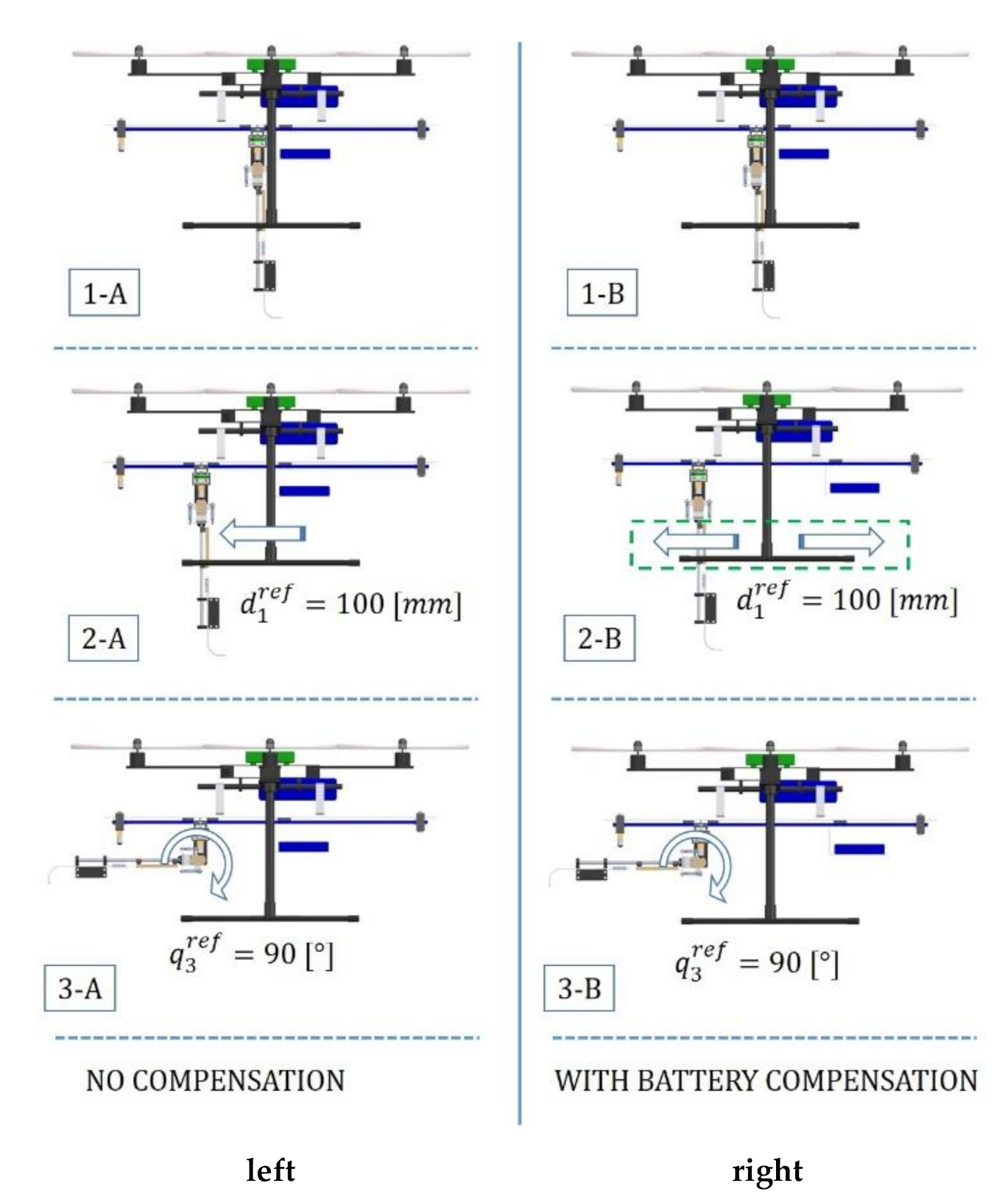
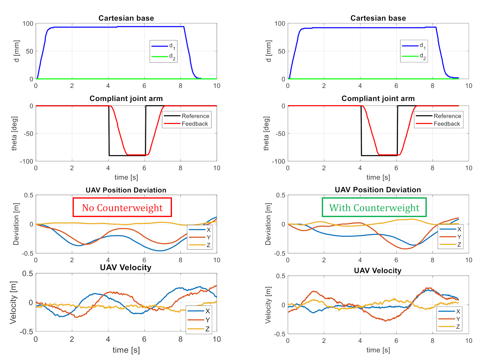
The positioning accuracy of the end effector is also affected by the dynamic coupling between the aerial platform and the manipulator, as the movement of the Cartesian base causes a variation of the center of mass and a reaction torque over the multirotor. The X–axis linear guide in Figure 4 incorporates a counterweight mechanism that moves the manipulator battery synchronized with the Y–axis guide, so the mass distribution is more symmetric, but at expenses of reducing the range of d 1 by half. The goal of this experiment is to evaluate the effectiveness of this mechanism in a flight test, showing the evolution of the position and velocity of the multirotor when the Y–axis structure and the compliant arm move in the forward direction while the multirotor is controlled in stabilize mode. The position controller is disabled in order to observe more clearly the desired effect, using a laser tracker to measure the multirotor position. Figure 11 ilustrates the execution of the experiment, representing the signals of interest in Figure 12.
The manipulator is initially at rest position, d 1 = 0 , d 2 = 0 , q 3 = 0 . Between t = 0 and t = 1 [s], the Cartesian base is displaced to d 1 = 95 [mm], and between t = 4 and t = 5 [s] q 3 is rotated from 0 to 90°. Note that the rotation of the joint cannot be compensated with the counter-weight mass. As can be seen on the lower part of Figure 12, the perturbation in the position and velocity of the multirotor along the X–axis (blue line) is more evident when the counterweight mechanism is disabled.

5.3. Monitoring Linear Deflection in Grabbing Conditions

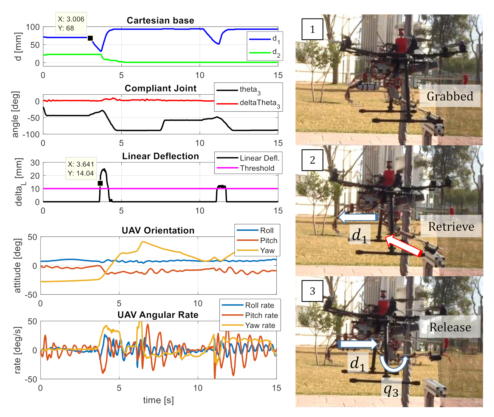
The link of the compliant arm is equipped with an elastic force sensor consisting of a pair of extension springs and a linear potentiometer that measures the deflection along the link (Figure 5). This mechanism is used in this experiment to detect and react against overloads in grabbing situations, for example when the arm tries to retrieve an object that is too heavy to be grasped or it is anchored to a fixed point. This situation is depicted in Figure 13. In order to avoid the destabilization of the attitude controller due to the interaction forces, the linear deflection is monitored in such a way that the gripper is released if the deflection exceeds a threshold of 10 (mm), corresponding to a force of around 3 (N). The compliant joint is controlled imposing a zero torque reference, according to the controller given by Equation (20), so the reaction torque in the pitch angle of the multirotor is relatively low. Figure 13 shows the monitoring-release capability on flight, representing the position of the Cartesian base, along with the linear deflection, the joint torque and the orientation of the multirotor. Once the support structure is grabbed at t = 3 [s], the X–axis guide moves backwards trying to retrieve the object. At t = 3.6 [s], the linear deflection threshold is exceeded, so the Cartesian base reacts by moving the gripper forwards while the compliant joint is rotated to release the bar. The process is repeated at t = 10 [s]. The hexa-rotor was controlled in stabilize mode.

5.4. Contact Force Control

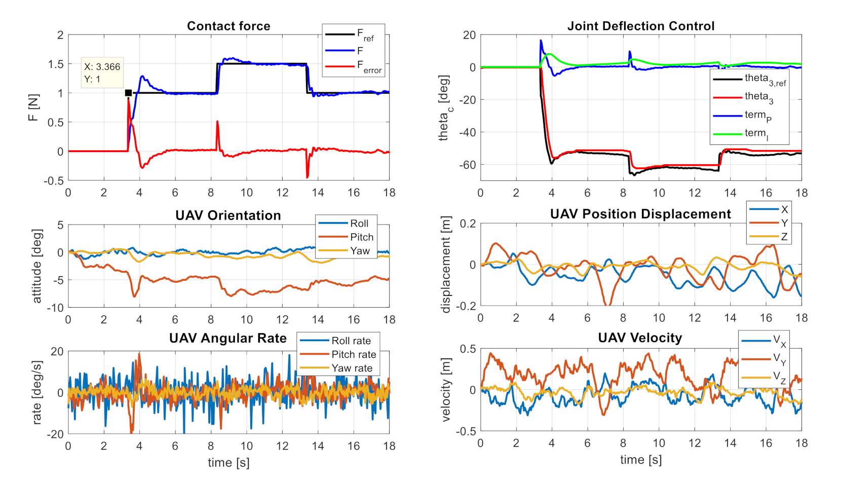
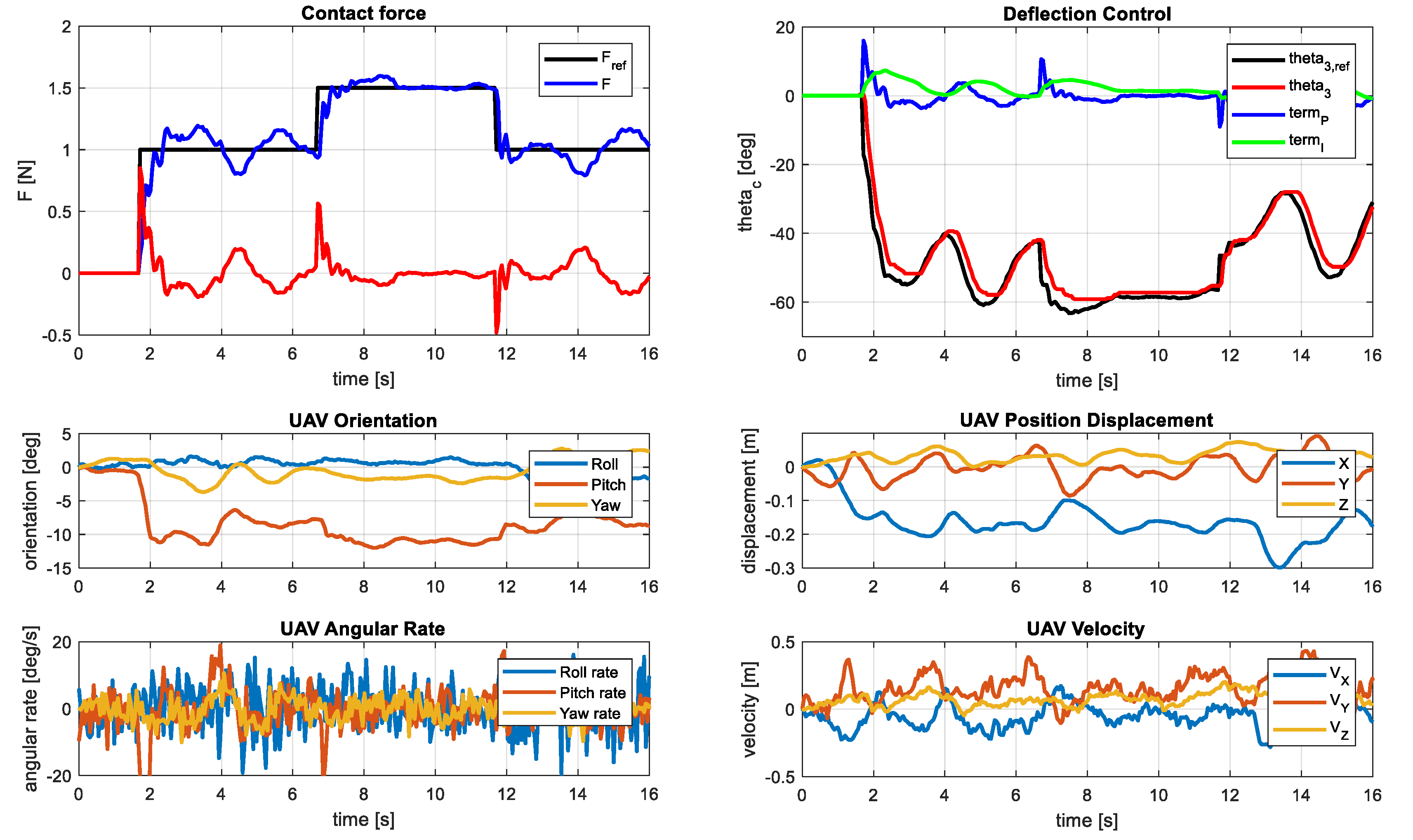
This experiment is intended to evaluate the performance of the contact force controller described in Section 4.2 and the effect over the attitude controller of the hexa-rotor platform. A sequence of images taken from the video is depicted in Figure 14. The Cartesian base and the compliant joint arm are initially at rest position ( d 1 = 0 , d 2 = 0 , q 3 = 0 ). Once the hexa-rotor is close to the contact point, the Cartesian base moves the output link in the forward direction until the collision with the obstacle is detected at t = 3.36 [s]. The deflection detection threshold is set to θ 3 t h = 2 °. Then, the PI force controller is activated, generating the force stair reference represented in Figure 15. As it can be seen, the pushing force is compensated by the attitude controller increasing the reference in the pitch angle, so the thrust of the multirotor is projected in the X–axis. The experiment was repeated again in order to validate the results, represented in Figure 16. The ability to accommodate the compliant joint arm is more evident here, considering the deviation in the position of the multirotor. The contact force control is useful in tasks like sensor installation and retrieval, inspection by contact, or for moving objects in the environment.

6. Conclusions

This paper described an aerial manipulator consisting of a multirotor equipped with a 2–DOF Cartesian base (XY–axes) and a compliant arm with angular and linear deflection sensors that allow the estimation, monitoring and control of the interaction wrenches exerted on flight, improving safety in grabbing conditions. This new morphology presents several benefits with respect to revolute joint manipulators in terms of positioning accuracy, energy consumption, and effective workspace, thanks to mechanical construction with two transversal linear guide systems that support the translation of the compliant arm. The forward kinematic model shows that the map between the joint space and the Cartesian space, in which the intended task is usually defined, is almost straightforward, so the Cartesian coordinates (XYZ) can be controlled with the corresponding actuators, reducing in this way the kinematic coupling between the joints and, with it, the propagation of errors at the end effector. The lack of dead-zones around the base of the manipulator extends the effective workspace, particularly useful for object retrieval and store operations. In this sense, the experiments presented in the paper showed how the linear deflection sensor can be used to detect overloads when the arm tries to grab an object too heavy to be lifted, moving the Cartesian base to release it and preventing the stability of the aerial platform from being compromised. The experiments also show the possibility of exerting sustained contact forces with the compliant joint arm, and the effect of the battery counterweight over positioning accuracy (at the expense of reducing the motion range in the X–axis by half). Although the mechanism is able to compensate partially for the reaction wrenches caused by the displacement of the Y–axis structure in the pitch angle, its effectiveness is reduced when the compliant arm is rotated, so this may not be practical in some cases taking into account the limitation it imposes on the range of motion of the X–axis structure.

Author Contributions

Conceptualization, A.S.; validation, A.S and M.P.; writing—original draft preparation, A.S.; writing—review and editing, A.S. and G.H.; supervision, G.H. and A.O.; project administration, A.O.; funding acquisition, A.O. All authors have read and agreed to the published version of the manuscript.

Funding

This work was funded by the AERIAL-CORE (H2020-2019-871479) and HYFLIERS (H2020-ICT-25-2017-779411) projects funded by the European Commission; and the ARTIC (RTI2018-102224-B-I00) projects funded by the Spanish Ministerio de Economia, Industria, y Competitividad.

Informed Consent Statement

Not applicable.

Acknowledgments

Authors want to thank Antonio Enrique Jimenez-Cano for his support in the realization of the experiments.

Conflicts of Interest

The authors declare no conflict of interest.

References

  1. The AERIAL-CORE Project. Available online: https://aerial-core.eu/ (accessed on 28 December 2020).
  2. Suarez, A.; Real, F.; Vega, V.M.; Heredia, G.; Rodriguez-Castano, A.; Ollero, A. Compliant Bimanual Aerial Manipulation: Standard and Long Reach Configurations. IEEE Access 2020, 8, 88844–88865. [Google Scholar] [CrossRef]
  3. Trujillo, M.A.; Dios, J.R.M.-D.; Martín, C.; Viguria, A.; Ollero, A. Novel Aerial Manipulator for Accurate and Robust Industrial NDT Contact Inspection: A New Tool for the Oil and Gas Inspection Industry. Sensors 2019, 19, 1305. [Google Scholar] [CrossRef] [PubMed] [Green Version]
  4. Ollero, A.; Cortés, J.; Santamaria-Navarro, Àngel; Trujillo, M.A.; Balachandran, R.; Andrade-Cetto, J.; Rodriguez, A.; Heredia, G.; Franchi, A.; Antonelli, G.; et al. The AEROARMS Project: Aerial Robots with Advanced Manipulation Capabilities for Inspection and Maintenance. IEEE Robot. Autom. Mag. 2018, 25, 12–23. [Google Scholar] [CrossRef] [Green Version]
  5. Ikeda, T.; Yasui, S.; Fujihara, M.; Ohara, K.; Ashizawa, S.; Ichikawa, A.; Okino, A.; Oomichi, T.; Fukuda, T. Wall contact by octo-rotor UAV with one DoF manipulator for bridge inspection. In Proceedings of the 2017 IEEE/RSJ International Conference on Intelligent Robots and Systems (IROS), Vancouver, BC, Canada, 24–28 September 2017; pp. 5122–5127. [Google Scholar]
  6. Fumagalli, M.; Naldi, R.; Macchelli, A.; Forte, F.; Keemink, A.Q.L.; Stramigioli, S.; Carloni, R.; Marconi, L. Developing an Aerial Manipulator Prototype: Physical Interaction with the Environment. IEEE Robot. Autom. Mag. 2014, 21, 41–50. [Google Scholar] [CrossRef]
  7. Suarez, A.; Heredia, G.; Ollero, A. Design of an Anthropomorphic, Compliant, and Lightweight Dual Arm for Aerial Manipulation. IEEE Access 2018, 6, 29173–29189. [Google Scholar] [CrossRef]
  8. Seo, H.; Kim, S.; Kim, H.J. Aerial grasping of cylindrical object using visual servoing based on stochastic model predictive control. In Proceedings of the 2017 IEEE International Conference on Robotics and Automation (ICRA), Singapore, 29 May–3 June 2017; pp. 6362–6368. [Google Scholar]
  9. Chen, H.; Quan, F.; Fang, L.; Zhang, S. Aerial Grasping with a Lightweight Manipulator Based on Multi-Objective Optimization and Visual Compensation. Sensors 2019, 19, 4253. [Google Scholar] [CrossRef] [PubMed] [Green Version]
  10. Orsag, M.; Korpela, C.; Bogdan, S.; Oh, P. Valve turning using a dual-arm aerial manipulator. In Proceedings of the 2014 International Conference on Un-manned Aircraft Systems (ICUAS), Orlando, FL, USA, 27–30 May 2014; pp. 836–841. [Google Scholar]
  11. Hamaza, S.; Georgilas, I.; Fernandez, M.; Sanchez-Cuevas, P.J.; Richardson, T.; Heredia, G.; Ollero, A. Sensor Installation and Retrieval Operations Using an Unmanned Aerial Manipulator. IEEE Robot. Autom. Lett. 2019, 4, 2793–2800. [Google Scholar] [CrossRef] [Green Version]
  12. Wopereis, H.W.; Hoekstra, J.J.; Post, T.H.; Folkertsma, G.A.; Stramigioli, S.; Fumagalli, M. Application of substantial and sustained force to vertical surfaces using a quadrotor. In Proceedings of the 2017 IEEE International Conference on Robotics and Automation (ICRA), Singapore, 29 May–3 June 2017; pp. 2704–2709. [Google Scholar]
  13. Tognon, M.; Chavez, H.A.T.; Gasparin, E.; Sable, Q.; Bicego, D.; Mallet, A.; Lany, M.; Santi, G.; Revaz, B.; Cortés, J.; et al. A Truly-Redundant Aerial Manipulator System with Application to Push-and-Slide Inspection in Industrial Plants. IEEE Robot. Autom. Lett. 2019, 4, 1846–1851. [Google Scholar] [CrossRef] [Green Version]
  14. Chermprayong, P.; Zhang, K.; Xiao, F.; Kovac, M. An Integrated Delta Manipulator for Aerial Repair: A New Aerial Robotic System. IEEE Robot. Autom. Mag. 2019, 26, 54–66. [Google Scholar] [CrossRef]
  15. Shimahara, S.; Leewiwatwong, S.; Ladig, R.; Shimonomura, K. Aerial torsional manipulation employing multi-rotor flying robot. In Proceedings of the 2016 IEEE/RSJ International Conference on Intelligent Robots and Systems (IROS), Daejeon, Korea, 9–14 October 2016; pp. 1595–1600. [Google Scholar]
  16. Nguyen, H.N.; Park, S.; Lee, D. Aerial tool operation system using quadrotors as rotating thrust generators. In Proceedings of the IEEE International Conference on Intelligent Robots and Systems, Hamburg, Germany, 28 September–2 October 2015. [Google Scholar]
  17. Bellicoso, C.D.; Buonocore, L.R.; Lippiello, V.; Siciliano, B. Design, modeling and control of a 5-DoF light-weight robot arm for aerial manipulation. In Proceedings of the 2015 23rd Mediterranean Conference on Control and Automation (MED), Torremolinos, Spain, 16–19 June 2015; pp. 853–858. [Google Scholar]
  18. Cano, R.; Pérez, C.; Pruano, F.; Ollero, A.; Heredia, G. Mechanical design of a 6-DOF aerial manipulator for assembling structures using UAVs. In Proceedings of the 2nd RED-UAS 2013 Workshop on Research, Education and Development of Unmanned Aerial Systems, Compiegne, France, 20–22 November 2013. [Google Scholar]
  19. Suarez, A.; Heredia, G.; Ollero, A. Lightweight compliant arm with compliant finger for aerial manipulation and inspection. In Proceedings of the 2016 IEEE/RSJ International Conference on Intelligent Robots and Systems (IROS), Daejeon, Korea, 9–14 October 2016; pp. 4449–4454. [Google Scholar]
  20. Yuksel, B.; Mahboubi, S.; Secchi, C.; Bulthoff, H.H.; Franchi, A. Design, identification and experimental testing of a light-weight flexible-joint arm for aerial physical interaction. In Proceedings of the 2015 IEEE International Conference on Robotics and Automation (ICRA), Seattle, WA, USA, 26–30 May 2015; pp. 870–876. [Google Scholar]
  21. Miyazaki, R.; Paul, H.; Kominami, T.; Shimonomura, K. Wire-Suspended Device Control Based on Wireless Communication with Multirotor for Long Reach-Aerial Manipulation. IEEE Access 2020, 8, 172096–172104. [Google Scholar] [CrossRef]
  22. Paul, H.; Miyazaki, R.; Ladig, R.; Shimonomura, K. Landing of a Multirotor Aerial Vehicle on an Uneven Surface Using Multiple On-board Manipulators. In Proceedings of the 2019 IEEE/RSJ International Conference on Intelligent Robots and Systems (IROS), Venetian Macao, Macau, China, 4–8 November 2019; pp. 1926–1933. [Google Scholar]
  23. Bartelds, T.; Capra, A.; Hamaza, S.; Stramigioli, S.; Fumagalli, M. Compliant Aerial Manipulators: Toward a New Generation of Aerial Robotic Workers. IEEE Robot. Autom. Lett. 2016, 1, 477–483. [Google Scholar] [CrossRef] [Green Version]
  24. Cataldi, E.; Muscio, G.; Trujillo, M.A.; Rodriguez, Y.; Pierri, F.; Antonelli, G.; Caccavale, F.; Viguria, A.; Chiaverini, S.; Ollero, A. Impedance Control of an aerial-manipulator: Preliminary results. In Proceedings of the 2016 IEEE/RSJ International Conference on Intelligent Robots and Systems (IROS), Daejeon, Korea, 9–14 October 2016; pp. 3848–3853. [Google Scholar]
  25. Ruggiero, F.; Cacace, J.; Sadeghian, H.; Lippiello, V. Impedance control of VToL UAVs with a momentum-based external generalized forces estimator. In Proceedings of the 2014 IEEE International Conference on Robotics and Automation (ICRA), Hong Kong, China, 31 May–5 June 2014; pp. 2093–2099. [Google Scholar]
  26. Suarez, A.; Sanchez-Cuevas, P.J.; Heredia, G.; Ollero, A. Aerial Physical Interaction in Grabbing Conditions with Lightweight and Compliant Dual Arms. Appl. Sci. 2020, 10, 8927. [Google Scholar] [CrossRef]
  27. Tomic, T.; Haddadin, S. A unified framework for external wrench estimation, interaction control and collision reflexes for flying robots. In Proceedings of the 2014 IEEE/RSJ International Conference on Intelligent Robots and Systems, Chicago, IL, USA, 14–18 September 2014; pp. 4197–4204. [Google Scholar]
  28. Garcia-Cruz, X.; Sergiyenko, O.; Tyrsa, V.; López, M.R.; Hernández-Balbuena, D.; Rodriguez-Quiñonez, J.; Basaca-Preciado, L.; Mercorelli, P.; Quiñonez, J.C.R. Optimization of 3D laser scanning speed by use of combined variable step. Opt. Lasers Eng. 2014, 54, 141–151. [Google Scholar] [CrossRef]
  29. Lindner, L.; Sergiyenko, O.; Rivas-Lopez, M.; Ivanov, M.; Quiñonez, J.C.R.; Hernandez-Balbuena, D.; Fuentes, W.F.; Tyrsa, V.; Muerrieta-Rico, F.N.; Mercorelli, P. Machine vision system errors for unmanned aerial vehicle navigation. In Proceedings of the 2017 IEEE 26th International Symposium on Industrial Electronics (ISIE), Edinburgh, Scotland, 19–21 June 2017; pp. 1615–1620. [Google Scholar]
  30. Ruggiero, F.; Trujillo, M.A.; Cano, R.; Ascorbe, H.; Viguria, A.; Perez, C.; Lippiello, V.; Ollero, A.; Siciliano, B. A multilayer control for multirotor UAVs equipped with a servo robot arm. In Proceedings of the 2015 IEEE International Conference on Robotics and Automation (ICRA), Seattle, WA, USA, 26–30 May 2015; pp. 4014–4020. [Google Scholar]
  31. Lippiello, V.; Cacace, J.; Santamaria-Navarro, A.; Andrade-Cetto, J.; Trujillo, M.A.; Esteves, Y.R.; Viguria, A. Hybrid Visual Servoing With Hierarchical Task Composition for Aerial Manipulation. IEEE Robot. Autom. Lett. 2016, 1, 259–266. [Google Scholar] [CrossRef] [Green Version]
  32. Rajappa, S.; Ryll, M.; Bulthoff, H.H.; Franchi, A. Modeling, control and design optimization for a fully-actuated hexa-rotor aerial vehicle with tilted propellers. In Proceedings of the 2015 IEEE International Conference on Robotics and Automation (ICRA), Seattle, WA, USA, 26–30 May 2015; pp. 4006–4013. [Google Scholar]
  33. Ryll, M.; Bicego, D.; Franchi, A. Modeling and control of FAST-Hex: A fully-actuated by synchronized-tilting hexa-rotor. In Proceedings of the 2016 IEEE/RSJ International Conference on Intelligent Robots and Systems (IROS), Daejeon, Korea, 9–14 October 2016; pp. 1689–1694. [Google Scholar]
  34. Ryll, M.; Muscio, G.; Pierri, F.; Cataldi, E.; Antonelli, G.; Caccavale, F.; Bicego, D.; Franchi, A. 6D interaction control with aerial robots: The flying end-effector paradigm. Int. J. Robot. Res. 2019, 38, 1045–1062. [Google Scholar] [CrossRef] [Green Version]
  35. Bodie, K.; Brunner, M.; Pantic, M.; Walser, S.; Pfandler, P.; Angst, U.; Siegwart, R.; Nieto, J. An omni-directional aerial manipulation platform for contact-based inspection. In Proceedings of the Robotics: Science and Systems, Breisgau, Germany, 22–26 June 2019. [Google Scholar]
  36. Meier, L.; Honegger, D.; Pollefeys, M. PX4: A node-based multithreaded open source robotics framework for deeply embedded platforms. In Proceedings of the 2015 IEEE International Conference on Robotics and Automation (ICRA), Seattle, WA, USA, 26–30 May 2015; pp. 6235–6240. [Google Scholar]
  37. Lippiello, V.; Ruggiero, F. Cartesian Impedance Control of a UAV with a Robotic Arm. In Proceedings of the IFAC Proceedings Volumes, Dubrovnik, Croatia, 5–7 September 2012; Volume 45, pp. 704–709. [Google Scholar]
Figure 1. Cartesian manipulator (left) integrated in S550 hexarotor platform (right).
Applsci 11 01001 g001
Figure 2. Components of the Cartesian manipulator, indicating the center of mass of each structure (XYZ axes).
Applsci 11 01001 g002
Figure 3. Pololu micro metal gear motors employed in the XY axes’ timing pulley-belt transmission.
Applsci 11 01001 g003
Figure 4. Side (left) and front (right) views of the Cartesian aerial manipulator, indicating the components.
Applsci 11 01001 g004
Figure 5. Magnetic gripper supported by the compliant linear joint (left). Compliant joint actuator (right).
Applsci 11 01001 g005
Figure 6. Components and architecture of the Cartesian aerial manipulator with ground control station (GCS).
Applsci 11 01001 g006
Figure 7. Kinematic model of the Cartesian aerial manipulator.
Applsci 11 01001 g007
Figure 8. Volume of operation in the Cartesian manipulator (up) and in a 3-degrees of freedom (3-DOF) revolute joint arm (down).
Applsci 11 01001 g008
Figure 9. Functional blocks of the Cartesian aerial manipulator controller.
Applsci 11 01001 g009
Figure 10. Cartesian base calibration: reference and measured displacement (left), and control error (right) in X 0 Y 0 .
Applsci 11 01001 g010
Figure 11. Phases involved in the battery counterweight experiment: no battery (left), battery counterweight (right).
Applsci 11 01001 g011
Figure 12. Multirotor position deviation when the manipulator moves in the forward direction ( d 1 , q 3 ).
Applsci 11 01001 g012
Figure 13. Variables of interest (left) and sequence of images (right) in the force monitoring experiment.
Applsci 11 01001 g013
Figure 14. Sequence of images from the contact force control experiment.
Applsci 11 01001 g014
Figure 15. Contact force control experiment. Force reference and estimation (up, left), servo position and PI correction terms (up, right), multirotor position, velocity, orientation and angular rate (down).
Applsci 11 01001 g015
Figure 16. Contact force control experiment. Second test.
Applsci 11 01001 g016
Table 1. Specifications of the Cartesian manipulator and the compliant joint arm.
Cartesian ManipulatorCompliant Joint Arm
Actuator featuresStall torque: 0.3 Nm
Mass: 10 g, 120 RPM
Actuator featuresStall torque: 1.17 Nm
Stiffness: 1.4 Nm/rad
Linear rangeX–axis: 500 mm Rotation range ± 120°
Y–axis: 250 mmJoint deflection30°
Max. speed100 mm/sLink length250 mm
Total mass0.85 kg (including battery–2S LiPo, 1500 mAh)
Table 2. Mass and inertia parameters of the hexa-rotor platform and the different structures of the Cartesian manipulator relative to the center of mass. The cross inertial terms (Ixy, Ixz, Iyz) are omitted since their value is negligible.
StructureMass [kg]Ixx [kg·m2]Iyy [kg·m2]Izz [kg·m2]
Hexa-rotor1.271.9 × 10−21.8 × 10−23.0 × 10−2
X–axis0.27.9 × 10−56.8 × 10−36.8 × 10−3
Y–axis0.141.0 × 10−32.1 × 10−51.0 × 10−3
Servo0.083.4 × 10−53.0 × 10−51.0 × 10−5
Link0.096.0 × 10−46.0 × 10−41.1 × 10−5
Publisher’s Note: MDPI stays neutral with regard to jurisdictional claims in published maps and institutional affiliations.