sensors-logo

Journal Browser

Journal Browser

Position Sensor

A topical collection in Sensors (ISSN 1424-8220). This collection belongs to the section "Physical Sensors".

Viewed by 76626

Editors


E-Mail Website
Collection Editor
School of Electrical Engineering and Computing, University of Newcastle, Callaghan, NSW, Australia
Interests: Feedback Control Systems, Displacement Sensors, Nanopositioning
School of Engineering and Built Environment, Griffith University, QLD, Australia
Interests: microelectromechanical systems (MEMS); position sensors; microelectronics

Topical Collection Information

Dear Colleagues,

Measurements of physical displacement, position, and dimensions of objects are required in many technical applications such as precision manufacturing, scanning probe microscopy, profilometry, lithography, and robotics. The target distance in position sensing tasks can vary from the kilometer scale in LiDAR applications to nanometer scales in molecular and atomic manipulation tasks. Depending on the situation, the sensing accuracy can be compromised by numerous undesirable factors such as noise, crosstalk, nonlinearities, and target material properties. Other physical factors, such as limited power and space, atmospheric pressure, and temperature, also affect the adopted sensing material, fabrications procedure, and readout electronics. Hence, measurement and sensing of displacement and position is a continuously growing research field in the sensor industry and academia. However, recent survey publications focused on this field are limited and the variety of research fields related to sensing technology is considerably vast.

To facilitate rapid and effective advance of research in this field, Sensors aims to rapidly publish recent advances in the field of position and displacement sensors in a Topical Collection. We invite submissions bringing novelty or improvement in this field and addressing any aspect such as sensing materials, fabrication methods, sensing approaches, signal conditioning, speed of response, accuracy, resolution, and linearity. We are also interested in new applications and challenges in this field such as wearable sensors, proximity sensors, wrapage and flatness sensors, height or step height sensors, bed levelling sensors, and displacement sensors in positioning platforms, stages, scanning probes, and micromanipulation devices.

Dr. Ali Bazaei
Dr. Yong Zhu
Collection Editors

Manuscript Submission Information

Manuscripts should be submitted online at www.mdpi.com by registering and logging in to this website. Once you are registered, click here to go to the submission form. Manuscripts can be submitted until the deadline. All submissions that pass pre-check are peer-reviewed. Accepted papers will be published continuously in the journal (as soon as accepted) and will be listed together on the collection website. Research articles, review articles as well as short communications are invited. For planned papers, a title and short abstract (about 100 words) can be sent to the Editorial Office for announcement on this website.

Submitted manuscripts should not have been published previously, nor be under consideration for publication elsewhere (except conference proceedings papers). All manuscripts are thoroughly refereed through a single-blind peer-review process. A guide for authors and other relevant information for submission of manuscripts is available on the Instructions for Authors page. Sensors is an international peer-reviewed open access semimonthly journal published by MDPI.

Please visit the Instructions for Authors page before submitting a manuscript. The Article Processing Charge (APC) for publication in this open access journal is 2600 CHF (Swiss Francs). Submitted papers should be well formatted and use good English. Authors may use MDPI's English editing service prior to publication or during author revisions.

Keywords

  • Capacitive displacement sensors;
  • Magnetic displacement sensors: inductive, differential transformers (LVDT/RVDT), magnetoresisitive, magnetostrictive, hall effect, eddy current;
  • Optical displacement sensors: laser doppler vibrometers, optical fibers, optical lever detection, fiber Bragg grating;
  • Position encoders;
  • Resistive displacement sensors: potentiometers, piezoresistive, strain gauges;
  • Photodiode and CCD arrays;
  • Ultrasonic displacement sensors;
  • Piezoelectric displacement sensors

Published Papers (20 papers)

2025

Jump to: 2022, 2021, 2020

11 pages, 3661 KiB  
Communication
State-of-the-Art Design and Optimization of Strain Gauge-Type Load–Displacement Transducer for in In Situ Nanoindentation Systems
by Duhui Lu, Jianliang Liu, Mukai Wang and Sen Gu
Sensors 2025, 25(3), 609; https://doi.org/10.3390/s25030609 - 21 Jan 2025
Viewed by 349
Abstract
Force–displacement transducers are key components in in situ nanoindentation systems. The current existing capacitance-type transducers adopted in state-of-the-art commercial in situ nanoindentation systems are restricted by limited maximum ranges, and strain gauge-type transducers in the current in situ nanoindentation systems have the limitation [...] Read more.
Force–displacement transducers are key components in in situ nanoindentation systems. The current existing capacitance-type transducers adopted in state-of-the-art commercial in situ nanoindentation systems are restricted by limited maximum ranges, and strain gauge-type transducers in the current in situ nanoindentation systems have the limitation of low resolution and high values of mass. In the paper, we propose a mechanical design and improvement of a low-mass strain gauge-type force–displacement transducer capable of performing high resolution in situ nanoindentation measurements. The transducer mainly consisted of a parallelogram-shaped flexure hinge and two strain gauges. Air resolution, in situ resolution, and mass experiments reported an air force resolution of 5 μN, an in situ force resolution of 5 μN inside a scanning electron microscope (SEM), and a mass of 6.53 g of such a strain gauge-type load–displacement transducer. Then, the transducer was assembled into a newly developed in situ nanoindentation–atomic force microscope (AFM) hybrid system and a newly developed in situ nanoindentation system. The proposed design successfully performed nanoindentation measurements inside SEM. Based on the results, the proposed strain gauge-type transducer shows great advantages compared to the current state-of-the-art transducers. Full article
Show Figures

Figure 1

2022

Jump to: 2025, 2021, 2020

8 pages, 2427 KiB  
Communication
Electromagnetic Encoders Screen-Printed on Rubber Belts for Absolute Measurement of Position and Velocity
by Ferran Paredes, Cristian Herrojo, Ana Moya, Miguel Berenguel Alonso, David Gonzalez, Pep Bruguera, Claudia Delgado Simao and Ferran Martín
Sensors 2022, 22(5), 2044; https://doi.org/10.3390/s22052044 - 5 Mar 2022
Cited by 25 | Viewed by 2734
Abstract
This paper presents, for the first time, an absolute linear electromagnetic encoder consisting of a rubber belt with two chains of screen-printed metallic inclusions (rectangular patches). The position, velocity, and direction of the belt (the moving part) is determined by detecting the inclusions [...] Read more.
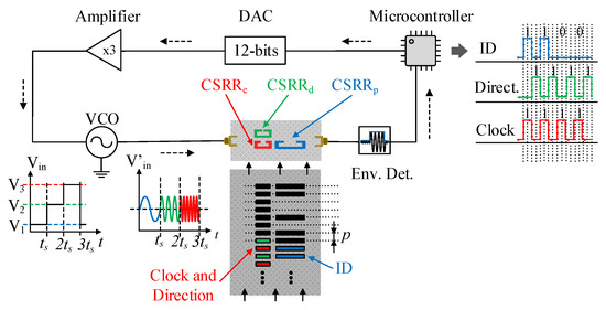
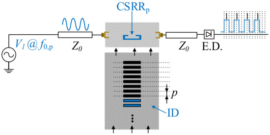
This paper presents, for the first time, an absolute linear electromagnetic encoder consisting of a rubber belt with two chains of screen-printed metallic inclusions (rectangular patches). The position, velocity, and direction of the belt (the moving part) is determined by detecting the inclusions when they cross the stator (the static part). The stator is a microstrip line loaded with three complementary split ring resonators (CSRRs), resonant elements exhibiting a resonance frequency perturbed by the presence of inclusions on top of them (contactless). The line is fed by three harmonic signals tuned to the resonance frequencies of the CSRRs. Such signals are generated by a voltage-controlled oscillator (VCO) managed by a microcontroller. The sensed data are retrieved from the pulses contained in the envelope functions of the respective amplitude modulated (AM) signals (caused by the belt motion) generated at the output port of the line. One of the signals provides the absolute belt position, determined by one of the chains, the encoded one. The information relative to the velocity and motion direction is contained in the other AM signals generated by the motion of the other chain, periodic, and thereby, uncoded. The spatial resolution of the system, a figure of merit, is 4 mm. Special emphasis is devoted to the printing process of the belt inclusions. Full article
Show Figures

Figure 1

10 pages, 8657 KiB  
Article
Achieving Long Distance Sensing Using Semiconductor Laser with Optical Feedback by Operating at Switching Status
by Bairun Nie, Yuxi Ruan, Yanguang Yu, Qinghua Guo, Can Fang, Jiangtao Xi, Jun Tong and Haiping Du
Sensors 2022, 22(3), 963; https://doi.org/10.3390/s22030963 - 26 Jan 2022
Cited by 6 | Viewed by 2994
Abstract
In this study, a novel distance sensing method is presented by using a semiconductor laser (SL) with optical feedback (OF) and operating the SL at a switching status happened between two nonlinear dynamic states (stable state and period-one state). In this case, without [...] Read more.
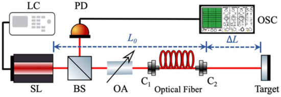
In this study, a novel distance sensing method is presented by using a semiconductor laser (SL) with optical feedback (OF) and operating the SL at a switching status happened between two nonlinear dynamic states (stable state and period-one state). In this case, without the need for any electronic or optical modulation devices, the laser intensity can be modulated in a square wave form due to the switching via utilizing the inherent SL dynamics. The periodicity in the switching enables us to develop a new approach for long-distance sensing compared to other SL with OF-based distance measurement systems and lift the relevant restrictions that existed in the systems. Moreover, the impact of system controllable parameters on the duty cycle of the square wave signals generated was investigated on how to maintain the proposed system robustly operating at the switching status. Both simulation and experiment verified the proposed sensing approach. Full article
Show Figures

Figure 1

2021

Jump to: 2025, 2022, 2020

21 pages, 10033 KiB  
Article
An Optimal Geometry Configuration Algorithm of Hybrid Semi-Passive Location System Based on Mayfly Optimization Algorithm
by Aihua Hu, Zhongliang Deng, Hui Yang, Yao Zhang, Yuhui Gao and Di Zhao
Sensors 2021, 21(22), 7484; https://doi.org/10.3390/s21227484 - 11 Nov 2021
Cited by 14 | Viewed by 2718
Abstract
In view of the demand of location awareness in a special complex environment, for an unmanned aerial vehicle (UAV) airborne multi base-station semi-passive positioning system, the hybrid positioning solutions and optimized site layout in the positioning system can effectively improve the positioning accuracy [...] Read more.
In view of the demand of location awareness in a special complex environment, for an unmanned aerial vehicle (UAV) airborne multi base-station semi-passive positioning system, the hybrid positioning solutions and optimized site layout in the positioning system can effectively improve the positioning accuracy for a specific region. In this paper, the geometric dilution of precision (GDOP) formula of a time difference of arrival (TDOA) and angles of arrival (AOA) hybrid location algorithm is deduced. Mayfly optimization algorithm (MOA) which is a new swarm intelligence optimization algorithm is introduced, and a method to find the optimal station of the UAV airborne multiple base station’s semi-passive positioning system using MOA is proposed. The simulation and analysis of the optimization of the different number of base stations, compared with other station layout methods, such as particle swarm optimization (PSO), genetic algorithm (GA), and artificial bee colony (ABC) algorithm. MOA is less likely to fall into local optimum, and the error of regional target positioning is reduced. By simulating the deployment of four base stations and five base stations in various situations, MOA can achieve a better deployment effect. The dynamic station configuration capability of the multi-station semi-passive positioning system has been improved with the UAV. Full article
Show Figures

Figure 1

19 pages, 5696 KiB  
Article
In-Tire Distributed Optical Fiber (DOF) Sensor for the Load Assessment of Light Vehicles in Static Conditions
by Martin Fontaine, Alex Coiret, Julien Cesbron, Vincent Baltazart and David Bétaille
Sensors 2021, 21(20), 6874; https://doi.org/10.3390/s21206874 - 16 Oct 2021
Cited by 5 | Viewed by 3415
Abstract
Modern vehicles are using control and safety driving algorithms fed by various evaluations such as wheel speeds or road environmental conditions. Wheel load evaluation could be useful for such algorithms, particularly for extreme vehicle loading or uneven loads. For now, smart tires are [...] Read more.
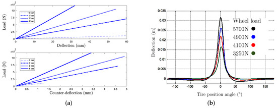
Modern vehicles are using control and safety driving algorithms fed by various evaluations such as wheel speeds or road environmental conditions. Wheel load evaluation could be useful for such algorithms, particularly for extreme vehicle loading or uneven loads. For now, smart tires are only equipped by tire pressure monitoring systems (TPMS) and temperature sensors. Manufacturers are still working on in-tire sensors, such as load sensors, to create the next generation of smart tires. The present work aims at demonstrating that a static tire instrumented with an internal optical fiber allows the wheel load estimation for every wheel angular position. Experiments have been carried out with a static tire loaded with a hydraulic press and instrumented with both an internal optical fiber and an embedded laser. Load estimation is performed both from tire deflection and contact patch length evaluations. For several applied loads from 2800 to 4800 N, optical fiber load estimation is realized with a relative error of 1% to 3%, almost as precisely as that with the embedded laser, but with the advantage of the load estimation regardless of the wheel angular position. In perspective, the developed methodology based on an in-tire optical fiber could be used for continuous wheel load estimation for moving vehicles, benefiting control and on-board safety systems. Full article
Show Figures

Figure 1

19 pages, 6799 KiB  
Article
Influence of Geometric Properties of Capacitive Sensors on Slope Error and Nonlinearity of Displacement Measurements
by Lars Daul, Tao Jin, Ingo Busch and Ludger Koenders
Sensors 2021, 21(13), 4270; https://doi.org/10.3390/s21134270 - 22 Jun 2021
Cited by 5 | Viewed by 4001
Abstract
Capacitive sensors are widely used in industrial applications, such as CNC machine tools, where reliable positioning in the micrometer range with nanometer accuracy is required. Hence, these sensors are operated in harsh industrial environments. The accuracy of these sensors is mainly limited by [...] Read more.
Capacitive sensors are widely used in industrial applications, such as CNC machine tools, where reliable positioning in the micrometer range with nanometer accuracy is required. Hence, these sensors are operated in harsh industrial environments. The accuracy of these sensors is mainly limited by slope errors and nonlinearities. In practice, the required accuracy of these sensors is achieved by a calibration against a metrological high-quality reference such as interferometric displacement measurement systems. This usually involves the use of high-order polynomials as calibration functions based on empirical data. In metrology, this is only the second-best approach and has disadvantages in terms of stability over the measurement range of the instrument. In addition, the validity of these empirical calibrations over time is questionable, and the associated uncertainty can only be roughly estimated. This makes regular recalibration of such sensors at short intervals mandatory to ensure the reliability of the displacement measurement. In this paper, we report on our investigations of the different parameters that affect the accuracy of capacitive sensors. Since the capacitance of these sensors results from the electric fields that build up between the electrodes, these field lines are calculated using FEM simulation models for typical commercial sensors. In the following the influence of various geometric parameters such as edge radius, guard ring size and shape, or thickness of the electrodes are individually analyzed according to their impact on the accuracy of these sensors. Based on these simulations, the deviations of the capacitance as they arise for real detector geometries can then be compared with idealized, de facto unrealizable parallel plate capacitors. This methodology allows overall uncertainty of capacitive sensors to be decomposed into their individual components and sorted in terms of their contribution to the uncertainty budget. The individual FEM-based analysis then enables a systematic analysis of the sources of uncertainty and, thus, reveals possibilities to improve manufacturing processes for capacitive sensors, to put these sensors on a solid metrological basis, and to improve the performance of these displacement measurement systems in the long run, i.e., to provide better sensors for the application. Full article
Show Figures

Figure 1

14 pages, 3747 KiB  
Article
Upconversion Spectral Rulers for Transcutaneous Displacement Measurements
by Melissa M. Suckey, Donald W. Benza, John D. DesJardins and Jeffrey N. Anker
Sensors 2021, 21(10), 3554; https://doi.org/10.3390/s21103554 - 20 May 2021
Cited by 2 | Viewed by 2715
Abstract
We describe a method to measure micron to millimeter displacement through tissue using an upconversion spectral ruler. Measuring stiffness (displacement under load) in muscles, bones, ligaments, and tendons is important for studying and monitoring healing of injuries. Optical displacement measurements are useful because [...] Read more.
We describe a method to measure micron to millimeter displacement through tissue using an upconversion spectral ruler. Measuring stiffness (displacement under load) in muscles, bones, ligaments, and tendons is important for studying and monitoring healing of injuries. Optical displacement measurements are useful because they are sensitive and noninvasive. Optical measurements through tissue must use spectral rather than imaging approaches because optical scattering in the tissue blurs the image with a point spread function typically around the depth of the tissue. Additionally, the optical measurement should have low background and minimal intensity dependence. Previously, we demonstrated a spectral encoder using either X-ray luminescence or fluorescence, but the X-ray luminescence required an expensive X-ray source and used ionizing radiation, while the fluorescence sensor suffered from interference from autofluorescence. Here, we used upconversion, which can be provided with a simple fiber-coupled spectrometer with essentially autofluorescence-free signals. The upconversion phosphors provide a low background signal, and the use of closely spaced spectral peaks minimizes spectral distortion from the tissue. The small displacement noise level (precision) through tissue was 2 µm when using a microscope-coupled spectrometer to collect light. We also showed proof of principle for measuring strain on a tendon mimic. The approach provides a simple method to study biomechanics using implantable sensors. Full article
Show Figures

Figure 1

16 pages, 4242 KiB  
Article
Strain Transfer Function of Distributed Optical Fiber Sensors and Back-Calculation of the Base Strain Field
by Sangyoung Yoon, Meadeum Yu, Eunho Kim and Jaesang Yu
Sensors 2021, 21(10), 3365; https://doi.org/10.3390/s21103365 - 12 May 2021
Cited by 10 | Viewed by 3259
Abstract
Distributed optical fiber sensors are a promising technology for monitoring the structural health of large-scale structures. The fiber sensors are usually coated with nonfragile materials to protect the sensor and are bonded onto the structure using adhesive materials. However, local deformation of the [...] Read more.
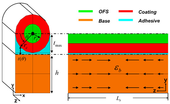
Distributed optical fiber sensors are a promising technology for monitoring the structural health of large-scale structures. The fiber sensors are usually coated with nonfragile materials to protect the sensor and are bonded onto the structure using adhesive materials. However, local deformation of the relatively soft coating and adhesive layers hinders strain transfer from the base structure to the optical fiber sensor, which reduces and distorts its strain distribution. In this study, we analytically derive a strain transfer function in terms of strain periods, which enables us to understand how the strain reduces and is distorted in the optical fiber depending on the variation of the strain field. We also propose a method for back-calculating the base structure’s strain field using the reduced and distorted strain distribution in the optical fiber sensor. We numerically demonstrate the back-calculation of the base strain using a composite beam model with an open hole and an attached distributed optical fiber sensor. The new strain transfer function and the proposed back-calculation method can enhance the strain field estimation accuracy in using a distributed optical fiber sensor. This enables us to use a highly durable distributed optical fiber sensor with thick protective layers in precision measurement. Full article
Show Figures

Figure 1

14 pages, 1676 KiB  
Article
A Magnetic Food Texture Sensor and Comparison of the Measurement Data of Chicken Nuggets
by Hiroyuki Nakamoto, Yuya Nagahata and Futoshi Kobayashi
Sensors 2021, 21(10), 3310; https://doi.org/10.3390/s21103310 - 11 May 2021
Cited by 7 | Viewed by 3883
Abstract
Food texture is one of the important quality indicators in foodstuffs, along with appearance and flavor, contributing to taste and odor. This study proposes a novel magnetic food texture sensor that corresponds to the tactile sensory capacity of the human tooth. The sensor [...] Read more.
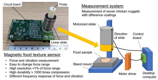
Food texture is one of the important quality indicators in foodstuffs, along with appearance and flavor, contributing to taste and odor. This study proposes a novel magnetic food texture sensor that corresponds to the tactile sensory capacity of the human tooth. The sensor primarily consists of a probe, linear slider, spring, and circuit board. The probe has a cylindrical shape and includes a permanent magnet. Both sides of the spring are fixed to the probe and circuit board. The linear slider enables the smooth, single-axis motion of the probe during food compression. Two magnetoresistive elements and one inductor on the circuit board measured the probe’s motion. A measurement system then translates the measurement data collected by the magnetoresistive elements into compression force by means of a calibration equation. Fundamental experiments were performed to evaluate the range, resolution, repetitive durability of force, and differences in the frequency responses. Furthermore, the sensor was used to measure seven types of chicken nuggets with different coatings. The difference between the force and vibration measurement data is revealed on the basis of the discrimination rate of the nuggets. Full article
Show Figures

Graphical abstract

28 pages, 11017 KiB  
Review
Position Sensors for Industrial Applications Based on Electromagnetic Encoders
by Ferran Paredes, Cristian Herrojo and Ferran Martín
Sensors 2021, 21(8), 2738; https://doi.org/10.3390/s21082738 - 13 Apr 2021
Cited by 21 | Viewed by 5889
Abstract
Optical and magnetic linear/rotary encoders are well-known systems traditionally used in industry for the accurate measurement of linear/angular displacements and velocities. Recently, a different approach for the implementation of linear/rotary encoders has been proposed. Such an approach uses electromagnetic signals, and the working [...] Read more.
Optical and magnetic linear/rotary encoders are well-known systems traditionally used in industry for the accurate measurement of linear/angular displacements and velocities. Recently, a different approach for the implementation of linear/rotary encoders has been proposed. Such an approach uses electromagnetic signals, and the working principle of these electromagnetic encoders is very similar to the one of optical encoders, i.e., pulse counting. Specifically, a transmission line based structure fed by a harmonic signal tuned to a certain frequency, the stator, is perturbed by encoder motion. Such encoder consists in a linear or circular chain (or chains) of inclusions (metallic, dielectric, or apertures) on a dielectric substrate, rigid or flexible, and made of different materials, including plastics, organic materials, rubber, etc. The harmonic signal is amplitude modulated by the encoder chain, and the envelope function contains the information relative to the position and velocity. The paper mainly focuses on linear encoders based on metallic and dielectric inclusions. Moreover, it is shown that synchronous electromagnetic encoders, able to provide the quasi-absolute position (plus the velocity and direction of motion in some cases), can be implemented. Several prototype examples are reviewed in the paper, including encoders implemented by means of additive process, such as 3D printed and screen-printed encoders. Full article
Show Figures

Figure 1

17 pages, 2956 KiB  
Article
Integrated, Speckle-Based Displacement Measurement for Lateral Scanning White Light Interferometry
by Gert Behrends, Dirk Stöbener and Andreas Fischer
Sensors 2021, 21(7), 2486; https://doi.org/10.3390/s21072486 - 2 Apr 2021
Cited by 6 | Viewed by 2891
Abstract
Lateral scanning white light interferometry (LSWLI) is a promising technique for high-resolution topography measurements on moving surfaces. To achieve resolutions typically associated with white light interferometry, accurate information on the lateral displacement of the measured surface is essential. Since the uncertainty requirement for [...] Read more.
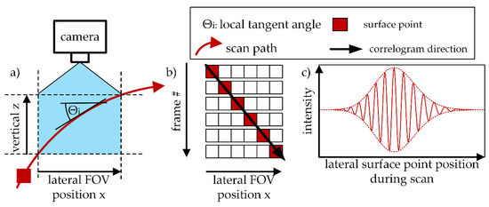
Lateral scanning white light interferometry (LSWLI) is a promising technique for high-resolution topography measurements on moving surfaces. To achieve resolutions typically associated with white light interferometry, accurate information on the lateral displacement of the measured surface is essential. Since the uncertainty requirement for a respective displacement measurement is currently not known, Monte Carlo simulations of LSWLI measurements are carried out at first to assess the impact of the displacement uncertainty on the topography measurement. The simulation shows that the uncertainty of the displacement measurement has a larger influence on the total height uncertainty than the uncertainty of the displacing motion itself. Secondly, a sufficiently precise displacement measurement by means of digital speckle correlation (DSC) is proposed that is fully integrated into the field of view of the interferometer. In contrast to externally applied displacement measurement systems, the integrated combination of DSC with LSWLI needs no synchronization and calibration, and it is applicable for translatory as well as rotatory scans. To demonstrate the findings, an LSWLI setup with integrated DSC measurements is realized and tested on a rotating cylindrical object with a surface made of a linear encoder strip. Full article
Show Figures

Figure 1

11 pages, 4180 KiB  
Communication
Soft Inductive Coil Spring Strain Sensor Integrated with SMA Spring Bundle Actuator
by Kyungjun Choi, Seong Jun Park, Mooncheol Won and Cheol Hoon Park
Sensors 2021, 21(7), 2304; https://doi.org/10.3390/s21072304 - 25 Mar 2021
Cited by 9 | Viewed by 4771
Abstract
This study proposes a soft inductive coil spring (SICS) strain sensor that can measure the strain of soft actuators. The SICS sensor, produced by transforming a shape memory alloy (SMA) wire with the same materials as that of an SMA spring bundle actuator [...] Read more.
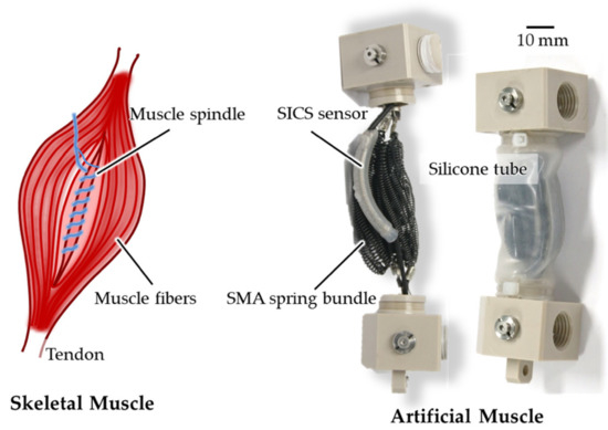
This study proposes a soft inductive coil spring (SICS) strain sensor that can measure the strain of soft actuators. The SICS sensor, produced by transforming a shape memory alloy (SMA) wire with the same materials as that of an SMA spring bundle actuator (SSBA) into a coil spring shape, measures inductance changes according to length changes. This study also proposes a manufacturing method, output characteristics of the SICS sensor applicable to the SSBA among soft actuators, and the structure of the SICS sensor-integrated SSBA (SI-SSBA). In the SI-SSBA, the SMA spring bundle and SICS sensor have structures corresponding to the muscle fiber and spindle of the skeletal muscle, respectively. It is demonstrated that when a robotic arm with one degree of freedom is operated by attaching two SI-SSBAs in an antagonistic structure, the displacement of the SSBA can be measured using the proposed strain sensor. The output characteristics of the SICS sensor for the driving speed of the robotic arm were evaluated, and it was experimentally proven that the strain of the SSBA can be stably measured in water under a temperature change of 54 °C from 36 to 90 °C. Full article
Show Figures

Figure 1

24 pages, 4283 KiB  
Article
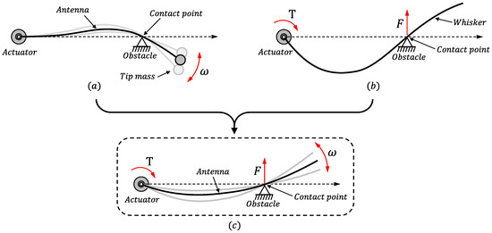
Improving the Detection of the Contact Point in Active Sensing Antennae by Processing Combined Static and Dynamic Information
by Luis Mérida-Calvo, Daniel Feliu-Talegón and Vicente Feliu-Batlle
Sensors 2021, 21(5), 1808; https://doi.org/10.3390/s21051808 - 5 Mar 2021
Cited by 6 | Viewed by 3944
Abstract
The design and application of sensing antenna devices that mimic insect antennae or mammal whiskers is an active field of research. However, these devices still require new developments if they are to become efficient and reliable components of robotic systems. We, therefore, develop [...] Read more.
The design and application of sensing antenna devices that mimic insect antennae or mammal whiskers is an active field of research. However, these devices still require new developments if they are to become efficient and reliable components of robotic systems. We, therefore, develop and build a prototype composed of a flexible beam, two servomotors that drive the beam and a load cell sensor that measures the forces and torques at the base of the flexible beam. This work reports new results in the area of the signal processing of these devices. These results will make it possible to estimate the point at which the flexible antenna comes into contact with an object (or obstacle) more accurately than has occurred with previous algorithms. Previous research reported that the estimation of the fundamental natural frequency of vibration of the antenna using dynamic information is not sufficient as regards determining the contact point and that the estimation of the contact point using static information provided by the forces and torques measured by the load cell sensor is not very accurate. We consequently propose an algorithm based on the fusion of the information provided by the two aforementioned strategies that enhances the separate benefits of each one. We demonstrate that the adequate combination of these two pieces of information yields an accurate estimation of the contacted point of the antenna link. This will enhance the precision of the estimation of points on the surface of the object that is being recognized by the antenna. Thorough experimentation is carried out in order to show the features of the proposed algorithm and establish its range of application. Full article
Show Figures

Figure 1

22 pages, 5675 KiB  
Article
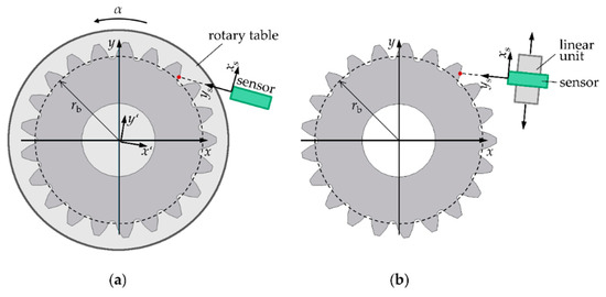
Gear Shape Measurement Potential of Laser Triangulation and Confocal-Chromatic Distance Sensors
by Marc Pillarz, Axel von Freyberg, Dirk Stöbener and Andreas Fischer
Sensors 2021, 21(3), 937; https://doi.org/10.3390/s21030937 - 30 Jan 2021
Cited by 32 | Viewed by 5265
Abstract
The demand for extensive gear shape measurements with single-digit µm uncertainty is growing. Tactile standard gear tests are precise but limited in speed. Recently, faster optical gear shape measurement systems have been examined. Optical gear shape measurements are challenging due to potential deviation [...] Read more.
The demand for extensive gear shape measurements with single-digit µm uncertainty is growing. Tactile standard gear tests are precise but limited in speed. Recently, faster optical gear shape measurement systems have been examined. Optical gear shape measurements are challenging due to potential deviation sources such as the tilt angles between the surface normal and the sensor axis, the varying surface curvature, and the surface properties. Currently, the full potential of optical gear shape measurement systems is not known. Therefore, laser triangulation and confocal-chromatic gear shape measurements using a lateral scanning position measurement approach are studied. As a result of tooth flank standard measurements, random effects due to surface properties are identified to primarily dominate the achievable gear shape measurement uncertainty. The standard measurement uncertainty with the studied triangulation sensor amounts to >10 µm, which does not meet the requirements. The standard measurement uncertainty with the confocal-chromatic sensor is <6.5 µm. Furthermore, measurements on a spur gear show that multiple reflections do not influence the measurement uncertainty when measuring with the lateral scanning position measurement approach. Although commercial optical sensors are not designed for optical gear shape measurements, standard uncertainties of <10 µm are achievable for example with the applied confocal-chromatic sensor, which indicates the further potential for optical gear shape measurements. Full article
Show Figures

Figure 1

14 pages, 3418 KiB  
Communication
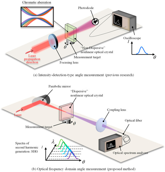
An Optical Frequency Domain Angle Measurement Method Based on Second Harmonic Generation
by Wijayanti Dwi Astuti, Hiraku Matsukuma, Masaru Nakao, Kuangyi Li, Yuki Shimizu and Wei Gao
Sensors 2021, 21(2), 670; https://doi.org/10.3390/s21020670 - 19 Jan 2021
Cited by 16 | Viewed by 4229
Abstract
This paper proposes a new optical angle measurement method in the optical frequency domain based on second harmonic generation with a mode-locked femtosecond laser source by making use of the unique characteristic of the high peak power and wide spectral range of the [...] Read more.
This paper proposes a new optical angle measurement method in the optical frequency domain based on second harmonic generation with a mode-locked femtosecond laser source by making use of the unique characteristic of the high peak power and wide spectral range of the femtosecond laser pulses. To get a wide measurable range of angle measurement, a theoretical calculation for several nonlinear optical crystals is performed. As a result, LiNbO3 crystal is employed in the proposed method. In the experiment, the validity of the use of a parabolic mirror is also demonstrated, where the chromatic aberration of the focusing beam caused the localization of second harmonic generation in our previous research. Moreover, an experimental demonstration is also carried out for the proposed angle measurement method. The measurable range of 10,000 arc-seconds is achieved. Full article
Show Figures

Figure 1

2020

Jump to: 2025, 2022, 2021

14 pages, 3278 KiB  
Article
Drift Reduction of a 4-DOF Measurement System Caused by Unstable Air Refractive Index
by Ruijun Li, Yongjun Wang, Pan Tao, Rongjun Cheng, Zhenying Cheng, Yongqing Wei and Xueming Dang
Sensors 2020, 20(21), 6329; https://doi.org/10.3390/s20216329 - 6 Nov 2020
Cited by 6 | Viewed by 2671
Abstract
Laser beam drift greatly influences the accuracy of a four degrees of freedom (4-DOF) measurement system during the detection of machine tool errors, especially for long-distance measurement. A novel method was proposed using bellows to serve as a laser beam shield and air [...] Read more.
Laser beam drift greatly influences the accuracy of a four degrees of freedom (4-DOF) measurement system during the detection of machine tool errors, especially for long-distance measurement. A novel method was proposed using bellows to serve as a laser beam shield and air pumps to stabilize the refractive index of air. The inner diameter of the bellows and the control mode of the pumps were optimized through theoretical analysis and simulation. An experimental setup was established to verify the feasibility of the method under the temperature interference condition. The results indicated that the position stability of the laser beam spot can be improved by more than 79% under the action of pumping and inflating. The proposed scheme provides a cost-effective method to reduce the laser beam drift, which can be applied to improve the detection accuracy of a 4-DOF measurement system. Full article
Show Figures

Figure 1

22 pages, 5458 KiB  
Article
Laser and LIDAR in a System for Visibility Distance Estimation in Fog Conditions
by Razvan-Catalin Miclea, Ciprian Dughir, Florin Alexa, Florin Sandru and Ioan Silea
Sensors 2020, 20(21), 6322; https://doi.org/10.3390/s20216322 - 5 Nov 2020
Cited by 21 | Viewed by 5690
Abstract
Visibility is a critical factor for transportation, even if we refer to air, water, or ground transportation. The biggest trend in the automotive industry is autonomous driving, the number of autonomous vehicles will increase exponentially, prompting changes in the industry and user segment. [...] Read more.
Visibility is a critical factor for transportation, even if we refer to air, water, or ground transportation. The biggest trend in the automotive industry is autonomous driving, the number of autonomous vehicles will increase exponentially, prompting changes in the industry and user segment. Unfortunately, these vehicles still have some drawbacks and one, always in attention and topical, will be treated in this paper—visibility distance issue in bad weather conditions, particularly in fog. The way and the speed with which vehicles will determine objects, obstacles, pedestrians, or traffic signs, especially in bad visibility, will determine how the vehicle will behave. In this paper, a new experimental set up is featured, for analyzing the effect of the fog when the laser and LIDAR (Light Detection And Ranging) radiation are used in visibility distance estimation on public roads. While using our experimental set up, in the laboratory, the information offered by these measurement systems (laser and LIDAR) are evaluated and compared with results offered by human observers in the same fog conditions. The goal is to validate and unitarily apply the results regarding visibility distance, based on information arrives from different systems that are able to estimate this parameter (in foggy weather conditions). Finally, will be notifying the drivers in case of unexpected situations. It is a combination of stationary and of moving systems. The stationary system will be installed on highways or express roads in areas prone to fog, while the moving systems are, or can be, directly installed on the vehicles (autonomous but also non-autonomous). Full article
Show Figures

Figure 1

10 pages, 12417 KiB  
Letter
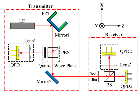
Dual-Frequency Doppler LiDAR Based on External Optical Feedback Effect in a Laser
by Zhuqiu Chen, Yanguang Yu, Yuxi Ruan, Bairun Nie, Jiangtao Xi, Qinghua Guo and Jun Tong
Sensors 2020, 20(21), 6303; https://doi.org/10.3390/s20216303 - 5 Nov 2020
Cited by 7 | Viewed by 2887
Abstract
A novel Dual-frequency Doppler LiDAR (DFDL) is presented where the dual-frequency light source is generated by using external optical feedback (EOF) effect in a laser diode (LD). By operating a LD at period-one (P1) state and choosing suitable LD related parameters, a dual-frequency [...] Read more.
A novel Dual-frequency Doppler LiDAR (DFDL) is presented where the dual-frequency light source is generated by using external optical feedback (EOF) effect in a laser diode (LD). By operating a LD at period-one (P1) state and choosing suitable LD related parameters, a dual-frequency light source can be achieved. Such a dual-frequency source has advantages of the minimum part-count scheme, low cost in implementation, and ease in optical alignment. Theory and system design are presented for the proposed DFDL for velocity measurement with high measurement resolution. The proposed design has a potential contribution to the Light Detection And Ranging (LiDAR) in practical engineering applications. Full article
Show Figures

Figure 1

13 pages, 3730 KiB  
Article
3D-Printed All-Dielectric Electromagnetic Encoders with Synchronous Reading for Measuring Displacements and Velocities
by Cristian Herrojo, Ferran Paredes and Ferran Martín
Sensors 2020, 20(17), 4837; https://doi.org/10.3390/s20174837 - 27 Aug 2020
Cited by 14 | Viewed by 2530
Abstract
In this paper, 3D-printed electromagnetic (or microwave) encoders with synchronous reading based on permittivity contrast, and devoted to the measurement of displacements and velocities, are reported for the first time. The considered encoders are based on two chains of linearly shaped apertures made [...] Read more.
In this paper, 3D-printed electromagnetic (or microwave) encoders with synchronous reading based on permittivity contrast, and devoted to the measurement of displacements and velocities, are reported for the first time. The considered encoders are based on two chains of linearly shaped apertures made on a 3D-printed high-permittivity dielectric material. One such aperture chain contains the identification (ID) code, whereas the other chain provides the clock signal. Synchronous reading is necessary in order to determine the absolute position if the velocity between the encoder and the sensitive part of the reader is not constant. Such absolute position can be determined as long as the whole encoder is encoded with the so-called de Bruijn sequence. For encoder reading, a splitter/combiner structure with each branch loaded with a series gap and a slot resonator (each one tuned to a different frequency) is considered. Such a structure is able to detect the presence of the apertures when the encoder is displaced, at short distance, over the slots. Thus, by injecting two harmonic signals, conveniently tuned, at the input port of the splitter/combiner structure, two amplitude modulated (AM) signals are generated by tag motion at the output port of the sensitive part of the reader. One of the AM envelope functions provides the absolute position, whereas the other one provides the clock signal and the velocity of the encoder. These synchronous 3D-printed all-dielectric encoders based on permittivity contrast are a good alternative to microwave encoders based on metallic inclusions in those applications where low cost as well as major robustness against mechanical wearing and aging effects are the main concerns. Full article
Show Figures

Figure 1

31 pages, 5436 KiB  
Review
Biometric Measurement of Anterior Segment: A Review
by Bin Liu, Chengwei Kang and Fengzhou Fang
Sensors 2020, 20(15), 4285; https://doi.org/10.3390/s20154285 - 31 Jul 2020
Cited by 10 | Viewed by 6688
Abstract
Biometric measurement of the anterior segment is of great importance for the ophthalmology, human eye modeling, contact lens fitting, intraocular lens design, etc. This paper serves as a comprehensive review on the historical development and basic principles of the technologies for measuring the [...] Read more.
Biometric measurement of the anterior segment is of great importance for the ophthalmology, human eye modeling, contact lens fitting, intraocular lens design, etc. This paper serves as a comprehensive review on the historical development and basic principles of the technologies for measuring the geometric profiles of the anterior segment. Both the advantages and drawbacks of the current technologies are illustrated. For in vivo measurement of the anterior segment, there are two main challenges that need to be addressed to achieve high speed, fine resolution, and large range imaging. One is the motion artefacts caused by the inevitable and random human eye movement. The other is the serious multiple scattering effects in intraocular turbid media. The future research perspectives are also outlined in this paper. Full article
Show Figures

Figure 1

Back to TopTop