A Smartphone Indoor Positioning System Using Hybrid Localization Technology


Department of Information and Communication Engineering, Chosun University, Gwangju 61452, Korea
*
Author to whom correspondence should be addressed.
Energies 2019, 12(19), 3702; https://doi.org/10.3390/en12193702
Submission received: 8 August 2019
/
Revised: 18 September 2019
/
Accepted: 24 September 2019
/
Published: 27 September 2019
(This article belongs to the Special Issue Wireless Communication Systems for Localization)
Abstract
:As smartphone built-in sensors, wireless technologies, and processor computing power become more advanced and global positioning system (GPS)-based positioning technologies are improving, location-based services (LBS) have become a part of our daily lives. At the same time, demand has grown for LBS applications in indoor environments, such as indoor path finding and navigation, marketing, entertainment, and location-based information retrieval. In this paper, we demonstrate the design and implementation of a smartphone-based indoor LBS system for location services consisting of smartphone applications and a server. The proposed indoor LBS system uses hybrid indoor positioning methods based on Bluetooth beacons, Geomagnetic field, Inertial Measurement Unit (IMU) sensors, and smartphone cameras and can be used for three types of indoor LBS applications. The performance of each positioning method demonstrates that our system retains the desired accuracy under experimental conditions. As these results illustrate that our system can maintain positioning accuracy to within 2 m 80% of the time, we believe our system can be a real solution for various indoor positioning service needs.
1. Introduction
Nowadays, smartphone users are increasingly exploiting their phones’ capabilities based on advanced sensor technology, wireless communications, and computing power. Smartphone services including multimedia streaming, health diagnostics, outdoor navigation, virtual reality (VR), and augmented reality (AR) are available now and getting popular. Specifically, location-based services (LBS) in outdoor environments have been developed based on the development of GPS-based precision positioning technology and map services including geographical information, street view, and satellite maps. Many consumers are already using these LBS on their personal smartphones. These services have been essentially requested in indoor environments. However, conventional GPS positioning has a limited ability to provide LBS in environments where signal reception is limited, such as in tunnels, underground, and inside buildings. To address this challenge, technologies for indoor positioning systems (IPS) have been studied. As GPS signals are unable to penetrate buildings, other technologies such as Wi-Fi, Bluetooth, Ultra Wide-Band (UWB), Ultrasonic wave, Radio Frequency Identification (RFID), Geomagnetic field, and Inertial Measurement Unit (IMU) have been used for positioning [1,2]. By using these positioning methods, the IPS can perform personal indoor smartphone navigation, marketing (shopping advertisements and proximity-based voucher sharing), location-based entertainment, indoor emergency localization, and so on. To deliver these services, IPS technologies are expected to provide reasonable accuracy for indoor positioning applications [3].
Researchers in academia and industry have focused on studying positioning techniques based on Wi-Fi and Bluetooth beacons due to the wide availability of Wi-Fi and Bluetooth in common places and mobile phones. Conventional RF positioning methods rely on the time of arrival (ToA), angle of arrival (AoA), and Received Signal Strength Indicator (RSSI) [4]. Currently, RSSI based fingerprint positioning is the most widely implemented method because of its acceptable accuracy for indoor environments [5]. However, its accuracy depends on the stability of RSSI and line of sight between transmitting and receiving devices [6,7,8]. Another widely-used positioning tool is the IMU sensor, which consists of accelerometers, magnetometers, and a gyroscope [9,10]. It is a popular sensor for human and vehicular navigation systems. Additionally, the implementation cost of an IMU is low, and pedestrian dead-reckoning (PDR) positioning using the IMU sensor does not need an extra infrastructure investment [11]. However, PDR using IMU sensors has an acceptable positioning accuracy only for a short distance, since it suffers from drift error in heading estimation over time. This drift error will be accumulated with PDR positioning using low cost IMU sensors embedded in the handheld device like a smartphone. These errors can be handled with sophisticated heading drift reduction methods. Another option for indoor positioning is adapting the fingerprint method to use the geomagnetic field as a fingerprint, since each building or structure has a unique magnetic fingerprint generated by the building and the Earth. Various magnetic field-based positioning methods have been introduced using machine learning and deep learning techniques [12,13].
Extensive research is going on to integrate two or more positioning technologies to mitigate the effect of distortion in RSSI and geomagnetic field-based IPS. Integration of multiple technologies can mitigate the limitations of each individual technology. Recently, various works have integrated RSSI-based positioning and PDR with the Kalman filter, particle filter and landmark, despite the relatively high computational costs of these methods [14,15,16].
In this paper, we design three IPS applications: indoor smartphone navigation, marketing, and location-based entertainment. These applications could be realized using Bluetooth Low Energy (BLE) based beacons, Pedestrian Dead Reckoning (PDR), geomagnetic field, and vision-based positioning methods for indoor environments. Different combinations of all these positioning technologies are chosen according to the purpose of each specific application. The effectiveness of each application can be achieved with the positioning combinations providing the proper positioning accuracy and meeting the requirements for the computation overhead in the smartphone.
The contents of our work are presented as follows. Section 2 shows previous related works for IPS. Section 3 presents the implementation approaches for three IPS applications and positioning methods used for them. The performance of the proposed IPS is described in Section 4, and the paper is concluded in Section 5.
2. Related Work
Over the decades, advances in various indoor positioning methods have been achieved. Most indoor positioning studies have focused on positioning performance enhancement using Wi-Fi, BLE, IMU sensors, and combinations of these technologies.
The commonly used BLE and Wi-Fi technologies generally make use of the fingerprinting method. Ref. [17] proposed an indoor positioning method using fingerprinting with BLE beacons that used 19 beacons to construct a fingerprint map for positioning the user. They showed that BLE beacons can be used more effectively than Wi-Fi devices for positioning; however, factors like multipath fading, attenuation, and interference cause RSSIs to fluctuate in indoor environments, affecting positioning results.
In recent years, geomagnetic field has been used for indoor positioning. This method has the advantage of not requiring any external infrastructure. Gozick et al. [18] showed that magnetic signatures are stable over time and can be used for positioning. Haverinen et al. [19] proposed a localization method using the geomagnetic field. They used a particle filter to determine the position of a robot and a person from any given initial point. However, positioning results from geomagnetic positioning systems are limited because the magnetic field is not always discernible from the inside of the building.
Nazemzadeh et al. [20] developed a camera vision positioning method using homography-based image processing algorithms [21] to measure the relative distance between the camera and a quick response (QR) code landmark. This method estimates the user’s current position using this relative distance and the knowledge of the reference position obtained from the marker.
Finally, hybrid positioning approaches try to overcome the limitations of individual technologies. For example, in [22,23], IMU-based PDR positioning is used along with Wi-Fi positioning systems. Since Wi-Fi positioning uses RSS fingerprints and provides better accuracy, it can help to remove the accumulated drift error of the IMU-based navigation system. For indoor navigation applications, IMU sensors can be used for PDR positioning; however, the latter has a lower positioning accuracy due to accumulated drift errors in user heading estimation. In [24,25], various methods have been introduced to reduce IMU sensor errors, but these have not completely removed location errors from IMU sensors. Therefore, the errors continue to affect their application in indoor positioning.
In another example, Zeng et al. [26] proposed a solution for indoor/outdoor positioning systems. Their approach integrates PDR and light and magnetic sensor signals for indoor positioning. In [27], PDR is integrated with a microelectromechanical system (MEMS) and Wi-Fi for pedestrian navigation using an extended Kalman filter. In [28], PDR is combined with IEEE 802.15.4a radio beacons. Although this hybrid positioning is accurate for a large area inside the building, the results are less accurate for small areas such as corridors. Adding geomagnetic positioning to the integrated PDR and RF positioning approach could increase accuracy at the cost of complexity and increased smartphone battery use.
3. Proposed Indoor Positioning System
3.1. Design Goals for Indoor Positioning System
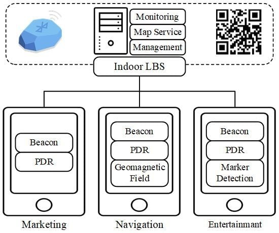
Smartphone IPS involves three components: a user device sensing the current environmental status, an RF infrastructure node installed inside the building to assist with positioning, and an LBS server communicating with the user device for estimating the current position and providing local indoor map information. In this paper, we describe a smartphone indoor positioning system supporting three LBS applications: indoor social marketing (App. 1), indoor navigation and tracking (App. 2), and indoor entertainment (App. 3). In Table 1, three different types of applications supported in our work are shown with positioning requirements and conditions for each indoor LBS application. That is, App. 1 is an LBS category for the service of social marketing, advertisement, and indoor monitoring which requesting positioning error limit approximately from 2 to 4 m. Also, App. 2 is for the service of indoor navigation and tracing which requesting the higher positioning error limit approximately from 1.5 to 3 m. Meanwhile, App. 3 is for the indoor entertainment service using smartphone camera, while requesting the error limit from 1.5 to 3 m.
We integrate four positioning technologies to provide reasonable positioning accuracy for each application: BLE beacon, geomagnetic field, IMU sensor, and vision camera. Generally, both Wi-Fi and BLE beacon positioning have been used to replace the GPS in indoor environments. In this paper, we select the BLE beacon for RF positioning for the following reasons. The first reason is that Wi-Fi does not usually provide better positioning accuracy than BLE. In research related to indoor positioning, ref. [29] showed that BLE beacon positioning was able to scan the signal once per second, while Wi-Fi positioning showed that it was able to scan the signal every 3–4 s. Also, ref. [30] showed that BLE beacon positioning had better signal resolution than Wi-Fi. The second reason is that BLE using a battery will be helpful for navigation applications during power outages and emergencies.
Since we use BLE beacons and a vision camera for the selected LBS applications, we can limit the required infrastructure components for indoor positioning to BLE beacons and paper-printed vision markers. These facilities do not require any external power source for indoor positioning-based services. Also, the proposed system can minimize implementation costs and time required to install and maintain the location service. The features for the proposed LBS are as follows: low power consumption of the user device, low-cost investment for the positioning infrastructure, and no extra positioning-aided device required for users.
In this paper, we show how to integrate the typical positioning methods for each application case and demonstrate the implemented positioning applications using the technology combinations. Specifically, a vision-based positioning with milliradian measurement is shown to help the positioning accuracy enhanced which can be useful for the indoor entertainment service using a smartphone camera for AR, MR, and so on.
3.2. Operation of Indoor Positioning System
Figure 1 shows the operation procedure of the proposed IPS using the multiple indoor positioning technologies selected based on the target application.
LBS system operation generally requires two steps: (1) an offline phase for drawing the navigation map, measuring the indoor fingerprint map, and learning the reference positioning information and (2) the online phase for estimating the current position.
During the offline phase, a fingerprint map is needed for the positioning reference and an indoor space map is needed for the navigation application. For the fingerprint map, we divided the service area into non-overlapping grid cells with the same size, then collected the RSSI of the beacon signal and intensity of the geomagnetic field at each reference point (RP) using the Bluetooth module and magnetometer in the smartphone. When we measured the RSSI of the beacon signal and intensity of the geomagnetic field, we aimed the measuring device in 4 heading directions (0°, 90°, 180°, and 270°), because signal strength can be influenced by the heading direction of the device.
During the online phase, the LBS applications built on the smartphone execute the positioning functions according to the target service application and then request the estimated current position by providing the observed BLE signal, geomagnetic field intensity, and QR marker information to the LBS server. The LBS server responds to the requests from the LBS client device (smartphone) asking for the indoor navigation map, fingerprint map, and LBS member identification. After the final indoor location is acquired from the server, the application starts its service on the client device depending on the current location. For example, an indoor navigation system created for this work searches for the shortest path to the destination using the Dijkstra algorithm and displays the direction on a 3D map obtained from the server.
3.3. Positioning Techniques for the Indoor Positioning System
3.3.1. Bluetooth Low Energy (BLE) Based Fingerprinting
BLE beacon based fingerprint positioning is widely used because of its advantages of low cost, low energy consumption, and small size. It operates in the spectrum range of 2.4–2.4835 GHz ISM band and enables an advertising packet transfer at very adjustable update rates. The frequency band is divided into 40 channels spaced at 2 MHz apart, and three channels are used for an advertisement. A BLE beacon uses these advertisement channels to broadcast its advertising packets continuously. The advertising packet allows a device to perceive proximity to a specific location-based on its RSSI. However, the application of RSSI for distance estimation is limited because it fluctuates over time due to factors like multipath fading, interference, and shadowing, as shown in Figure 2.
Therefore, RSSI can be used for coarse-grained location estimates. This RF behavior can be represented in a propagation model [31] given by
where is the transmit power, is the path loss at a particular reference distance (normally = 1 m), d is distance from the beacon, is the path loss exponent, and A is a Gaussian random variable with zero mean and variance .
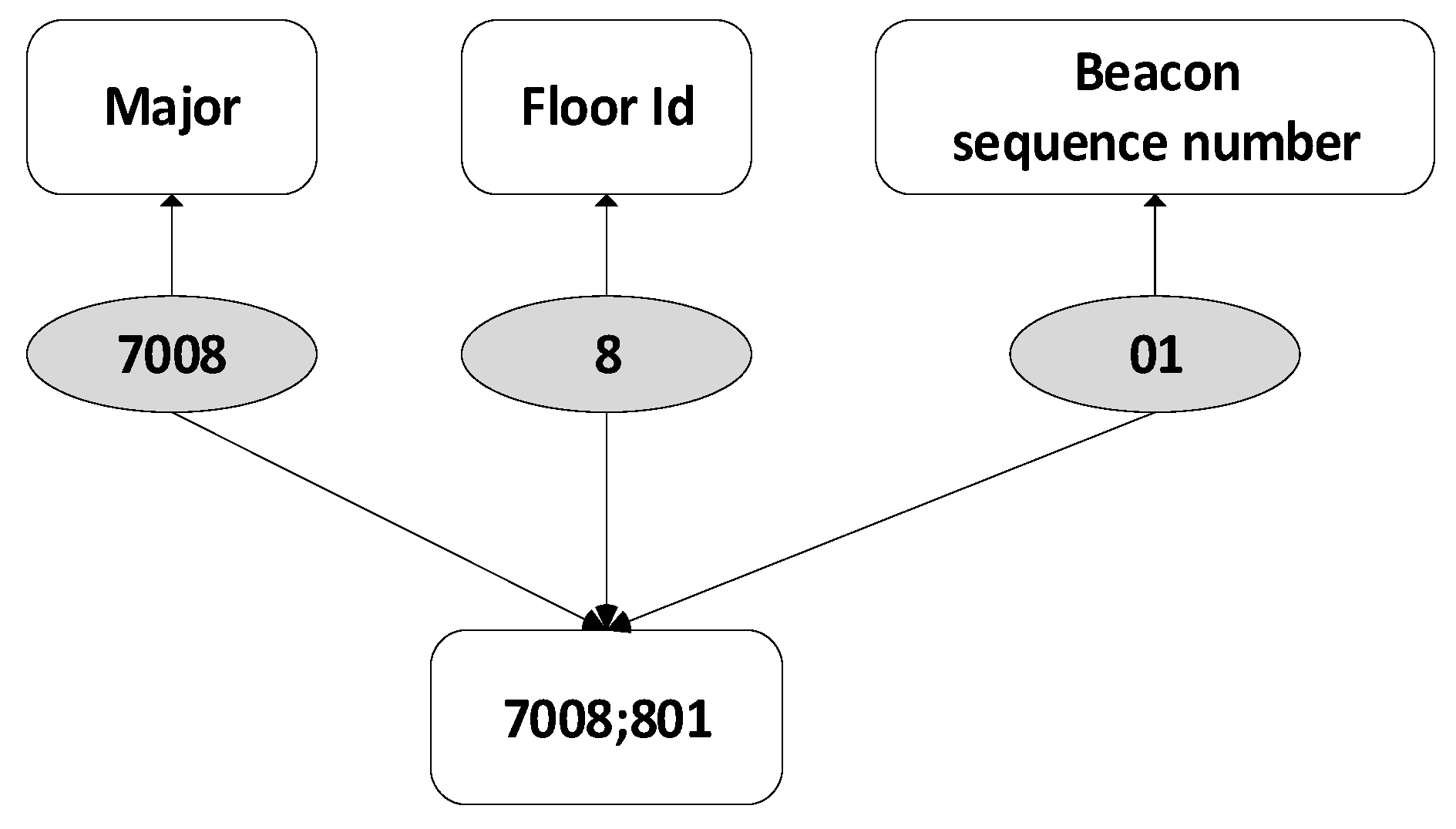
- BLE data collectionFor the BLE based positioning, we use a fingerprinting approach comparing the currently observed RSSI and the offline RSSI radio map. During the offline phase, the average RSSI fingerprints at each reference point are collected and stored in the database. Then, the fingerprints are compared to the online observed RSSIs. This observed RSSIs form an RSSI radio map in the format given bywhere F is the floor number, is the location of reference point i given by x and y coordinates , is the BLE beacon identifier, and is the mean RSSI of 100 samples taken from the jth BLE beacon signal in all four directions at the ith RP. At the smartphone, the BLE beacon identifiers can be observed by examining an advertisement packet sent from the neighboring beacons. The message format representing the RSSI radio map at each reference point sent by our positioning application to LBS server is shown in Figure 3.Figure 4 shows an example of a BLE device identifier constructed with the condition of 8th floor and beacon device number 1.
- RSSI fingerprint matching algorithmRSSIs from beacons are measured during the online phase and compared with the stored RSSI values for estimation of the current location. For the fingerprinting algorithm, our focus is on not only high accuracy but also low complexity of the positioning technologies for the realistic implementation of IPS. We use the weighted K nearest neighbor (WKNN) method, which is a conventional and effective matching method for a user’s current location [32,33]. The Euclidean distance () between the stored RSSI value () at the ith reference point and the online collected RSSI value () is given bywhere i is the number of reference points and j is the number of the BLE devices in range used for the RSSI comparison (1 ≤ i ≤ N, 1 ≤ j ≤ M). In this work, we select m strongest beacons per reference point in measuring the Euclidean distance (), where m is less than M. The small number of beacons in the RSSI fingerprint matching algorithm is for a lower computation load and quick response to the smartphone IPS application.The reference points for the estimation of the current location are sorted in the ascending order based on the Euclidean distance. Then, we select the first k reference points for WKNN-based position estimation, where the final location is given bywhere is the weight assigned to the ith reference point and (, ) is a coordinate of the ith reference point. To determine the weight assigned to the reference point, the inverse of is used as a weight to its respective reference point.
3.3.2. Pedestrian Dead Reckoning-Based Positioning (PDR)
Pedestrian dead reckoning (PDR) is a navigation technique for estimating current location using the previously determined location. PDR generally uses IMU sensors to estimate speeds over elapsed the time and course. PDR consists of three processes such as step detection, step length estimation, and heading estimation. The position-based on these components is determined by
where is the step length and is the heading angle at step t. That is, the position obtained from PDR () is equal to (). A feature of PDR is that the location estimation at the time is dependent on the location estimated at the time t. Also, the positioning accuracy is limited by the sensor precision, magnetic disturbances inside buildings, smartphone orientiation, and so on. Even though the accuracy of inertial sensors in the smartphone has recently increased, sensors still cannot provide higher accuracy for the indoor navigation application for a large area because of heading drift errors due to gyroscope bias. However, PDR is effective for short-term positioning over a limited area, thus it should be combined with other approaches for long-term, large-area positioning applications.
- Step detection: Step detection is based on the vertical reading of the accelerometer with respect to ground. Because vertical acceleration is affected by the tilting of the smartphone, we consider the magnitude of the acceleration () [34]. A step is detected when it satisfies the conditionwhere g is gravitational acceleration of the Earth and is the threshold acceleration.
- Step length estimation: Step length depends on various external factors like user age, height, gender, etc. Therefore, it is hard to determine the step length of the individual pedestrian using only the smartphone sensors. However, a universal equation can be formed to minimize the error in step length estimation using the Weinberg approach [35].
- Heading detection: Since the individual’s heading is not always in a straight line, estimation of direction is very important for indoor navigation. In this work, the heading orientation is determined by the smartphone orientation sensor and converted it to the testbed coordinate system (0°–360°).
3.3.3. Magnetic Field-Based Fingerprinting
Another positioning approach is magnetic field-based fingerprinting using magnetic sensor data obtained from a smartphone. Generally, the magnetic field creates certain anomalies due to distortions created by ferromagnetic materials such as the steel, iron, and reinforced concrete used in modern buildings [36]. Since these elements are distributed differently throughout the building, the magnetic field intensity (MFI) varies with respect to location inside the building. The distribution of MFI makes it a suitable sensor signal for use in indoor positioning applications. Magnetic field positioning is cost effective because it provides accuracy with no additional hardware requirements.
- Magnetic field data collectionMagnetic field data can be collected inside the building using the smartphone’s magnetic sensor. The smartphone can measure MFI in with respect to three axis (, , ). As in the BLE-based fingerprinting, MFI data observed at each reference point can be stored with the location coordinate of the reference point. The data stored in the database are formatted as , where , , and represent the three-axis intensities generated from the magnetic sensor, and represents the average magnetic field intensity given as:As in BLE beacon positioning, we collected the data in four directions at each reference point to reduce signal observation errors.
- Magnetic field fingerprint matching algorithmA nearest neighbor search is implemented to find the current indoor location. The root mean square deviation (RMSD) of the average MFI () between an offline dataset and an online dataset is performed to find the nearest neighbor [37]. The nearest neighbor is selected when it has the smallest RMSD. The formulation can be given aswhere , , , and are MFI observed at the ith reference point during the offline phase and , , , and are MFI observed at the user smartphone during the online phase. In this work, the locations of the reference points for magnetic field measurement can be same as the locations for BLE signal observation. By searching for the reference point with the lowest observation of , the magnetic field based fingerprinting method can determine the current location () during the online phase.
3.3.4. Vision Based Positioning
- Marker detectionVision-based positioning is a technique for estimating the current position using the visual characteristics of an object observed with the smartphone camera. The precondition of vision positioning is that the object must uniquely represent its location. Also, the object detection should not require too much computation for image processing. That is, vision markers for positioning should be easy to detect with unique features that represent its position, and the device for detecting markers should be able to read the information contained in the markers quickly and accurately. In this work, we chose QR codes as markers that satisfy the features of low computation power and fast detection even with a low-cost camera [38].
- Positioning algorithm using milliradian measurementBy scanning the QR code, we can get the physical location information of the QR code marker. Then, we can estimate the position of the marker-scanning device like a smartphone. We use milliradian measurement to observe the distance from the observer (smartphone) to the target (QR code) when the size of the target is known. Conversely, if the distance from the observer to the target is known, the size of the target can be estimated too. Because of these characteristics, milliradian measurement is actively used in the field for observation using equipment such as riflescopes, telescopes, and binoculars.Milliradian, often called a mil, is a unit for angular measurement which is defined as a thousandth of a radian (0.001 rad °). That is, milliradian is the angle formed when the length of a circular arc equals 1/1000 of the radius of the circle. Therefore, one mil approximately subtends one meter at a distance of one thousand meters as shown in Figure 5.To use the milliradian measurement for positioning, we first interpret the real size and position of the QR code marker by reading the code information with a smartphone. We used the open source library zxing [39] to read the position information from the QR code marker. Second, we measure the pixels per milliradian () like the mil scale in the binoculars using a viewing angle () of the camera. Generally, the camera device has its own , which can be found in the specifications of the image sensor and lens.where and are the number of pixels for width and height of the image frame captured from camera. Also, we can derive the number of horizontal and vertical mils, and , from the camera module’s viewing angles, and , as follows:Figure 6 shows an example of a QR code marker used for positioning. Since the smartphone captures an image frame from the camera module, the proposed algorithm searches the locator symbols in the QR code. The locator symbols are usually displayed in a large rectangular shape at three places: the lower left corner, the upper left corner, and the upper right corner. Additionally, a smaller symbol may be included in the lower right corner depending on the amount of data. In this study, we used three symbols (lower left, upper left, and upper right symbols) to measure the size of a marker on the image frame. We can measure the size of a marker in pixels using Euclidean distance between each symbol in the marker from the image frame, but we cannot measure the real size of a marker. Besides, even if the distance between the marker and the device is measured, the current position of the device can not be estimated without the position of the marker. For this reason, we included the following information in the QR code; real length between symbols in QR code () and setup angle () and position () of the marker. To measure the distance between marker and device using information from the QR code, we need to know the number of mils () and real length () of the marker.In (12), (), (), and () are the coordinates of each locator symbol on the QR code. When the marker is scanned in front of the device, and are almost the same because we used a square-shaped marker. However, becomes smaller when the marker is scanned from the left or right side while becomes smaller when the marker is scanned from the upper or lower side. Therefore, we selected the larger of the values and as the representative length () and mils () of marker as shown in (13).In (13), is the real length between and , and is the real length between and . If the horizontal euclidean distance is larger than , variables for horizontal values (, , ) are used to measure the distance. Otherwise variables for vertical values (, , ) are used to measure the distance. The distance from camera to marker is obtained by dividing the real size of the marker () by the mils of the marker ().Table 2 shows the experimental results of the proposed algorithm. To measure the accuracy, we used a printed QR code of 30 cm in width and height, and a Samsung SM-N950 smartphone Galaxy Note 8. The experimental result shows that the proposed algorithm can estimate the distance between marker and device accurately. In experiments using other smartphones (LG-F700, LM-G710, SM-G930), we found no significant difference in the measured distance according to the smartphone model.Figure 7 shows how proposed vision-based positioning calculates the device position, after obtaining the distance (D) from device to marker. To estimate the current smartphone’s position, we have to know the absolute position of the marker and the relative position of the device. As we mentioned before, we can read the information from marker such as QR code installation angle relative to magnetic north (), QR code location (coordinate and floor), and additional service information by scanning the QR code. Then, we can estimate the position of the device simply using (15).Here, is the heading angle of the device obtained from the PDR positioning.
3.4. Hybrid Positioning Algorithm
As it mentioned earlier, BLE beacon positioning can only give the approximate location of the device due to RF signal fluctuations caused by fading, shadowing, and wireless channel interference. But, Geomagnetic field positioning does not suffer from the effects of multipath and fading, but it can be affected by electronic devices and moving objects containing ferromagnetic materials. Geomagnetic field positioning is also limited because the same MFI patterns may be observed at multiple locations.
To compensate for the disadvantages of each positioning technique, we propose a hybrid positioning system. The proposed hybrid smartphone positioning system combines BLE beacons, geomagnetic field, PDR, and marker detection to overcome the limitations of each technology. Among these techniques, beacon and geomagnetic field positioning use fingerprinting because it can be used to implement a real-time positioning system with low complexity. However, using two fingerprint maps for real-time positioning will increase the battery consumption of the mobile device due to the increased transaction costs involved in accessing the fingerprint database. Considering real-time processing, the proposed hybrid positioning system minimizes the transactions for the fingerprint database by limiting the search range with the previous position and PDR.
3.4.1. App. 1: Marketing Service
For a commercial marketing service, the proposed system should be capable of estimating approximate position with minimum complexity. That is, the application designed for the commercial marketing service (App. 1) is expected to estimate the user’s position, while operating with low battery consumption. In our work, this positioning service is achieved using BLE beacons and IMU based PDR. This combination is designed so the two components compensate for each other’s shortcomings (instability of RSSI and drift error of PDR). The working procedure for the proposed hybrid positioning application using Beacon and PDR is shown in Figure 8.
App. 1 positioning finds the absolute position of the device by combining two sets of coordinates obtained from BLE beacon and PDR positionings. To minimize accumulated drift error of the PDR over time in the positioning process, App. 1 positioning periodically resets the PDR position using the coordinates obtained from the BLE positioning. The following steps show the procedure of the algorithm:
- BLE beacon-based positioning measures the coordinates (, ) by using WKNN fingerprinting. In the initialization phase of the system, the beacon positioning coordinates are determined as the current position because there has been no step yet (step = 0 in Figure 8).
- PDR detects the user’s steps, determines step length and heading direction, and then estimates the new PDR coordinate (, ), updating the position from the previous coordinate.
- The search range for beacon fingerprinting is created using PDR-estimated coordinates. That is, the beacon positioning coordinates are searched within a limited range around the PDR estimated coordinates.
- Final coordinates for the user’s location are measured by averaging the coordinates derived from the beacon and PDR positions.
- When the accumulated step is larger than a maximum value T, the number of the accumulated steps is reset to 0 and the coordinate obtained from PDR, (, ), is initialized with (, ) to eliminate the drift error of PDR positioning. This positioning refresh process is useful, because PDR approach is generally effective for short-term positioning over a limited area. In this work, we use 10 for T. This value of 10 for T has been empirically obtained through the testbed experiments.
3.4.2. App. 2: Navigation and Tracking Service
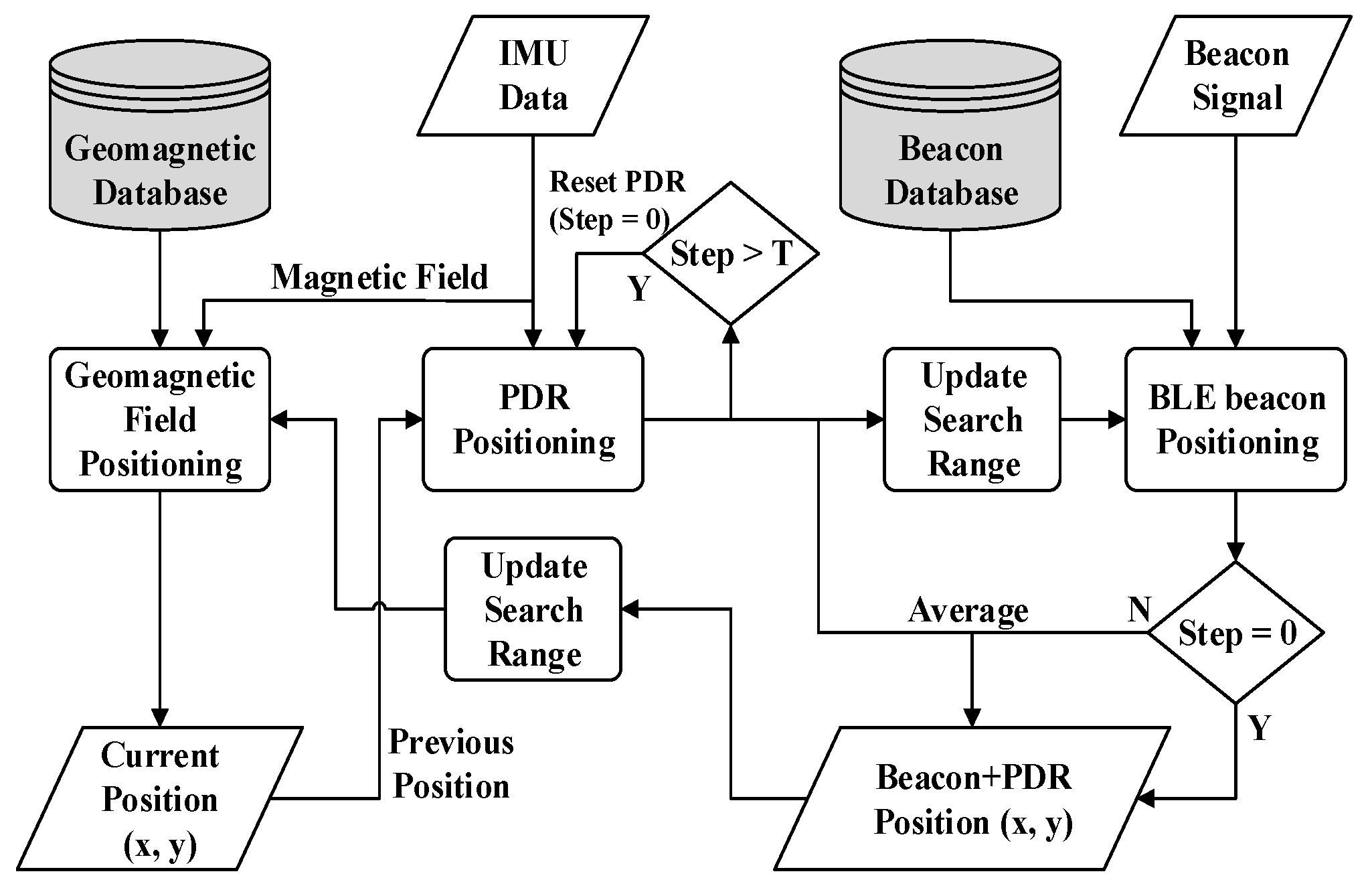
For services such as indoor navigation and human tracking, high positioning accuracy is needed even in places where it is not easy to find a destination, such as buildings with complicated interior structures and many passageways. Signal interference and multipath fading in these environments limit the use of BLE beacon indoor positioning. Moreover, to use additional RF-based positioning technology such as Wi-Fi and UWB, infrastructure costs and smartphone battery consumption become disadvantages. Therefore, the positioning algorithm for App. 2 adds magnetic field-based positioning to the App. 1 positioning method. Figure 9 shows the App. 2 positioning procedure.
The operation of beacon and PDR positioning is the same as App. 1, but in App. 2 the measured MFI in the IMU data is used for geomagnetic field positioning. In addition, the output from BLE and PDR positioning is used as an input for the geomagnetic field positioning to limit the search range for fingerprinting. Limiting the search range of the geomagnetic field fingerprinting helps minimize the positioning error range, even in the case when similar MFI values can be observed at different locations [13].
3.4.3. App. 3: Entertainment Service
There is an active indoor commercial entertainment movement to incorporate vision-based services such as VR, AR, or MR (Mixed Reality) combined with user-friendly content such as multimedia, games, shopping guides, and so on. Vision-based services require high positioning accuracy because they need to visualize the contents accurately at the user’s location. However, in an environment with many factors affecting the magnetic field and beacon signals, there are many challenges for positioning. For example, in exhibition or event venues, BLE beacon signals can be affected by people walking around, and the magnetic field can be distorted by electrical devices or obstacles containing ferromagnetic material. When positioning using beacon and magnetic field suffers from a large error, vision-based positioning techniques can be used. To develop a system with the minimum positioning error, App. 3 positioning combines beacon, PDR, and milliradian positioning to estimate the user’s current position.
With vision markers installed along the user moving path, the smartphone user can easily find a QR code marker and scan it for vision-based positioning along the way. In the position where the marker has been scanned, sub-meter positioning can be provided using milliradian positioning. When the marker is not available, beacon and PDR-based positions are used to update the current position.
Figure 10 shows the processing procedure of the proposed hybrid positioning method. The overall positioning process is similar to App. 1, but it has been combined with milliradian positioning. When the user directs the camera module of the device toward the QR code marker, the device reads the position information from the QR code on the marker. If position information is present in the scanned QR code, the proposed App. 3 estimates the current position using milliradian positioning. After the current position of the device has been obtained using milliradian positioning, App. 3 positioning gives it the highest priority to determine the current position because it has higher positioning accuracy than the beacon and PDR. The position estimated from PDR is updated with the position from the milliradian positioning. The BLE beacon and PDR positionings are mainly used where the marker is not scanned.
4. Performance Evaluation
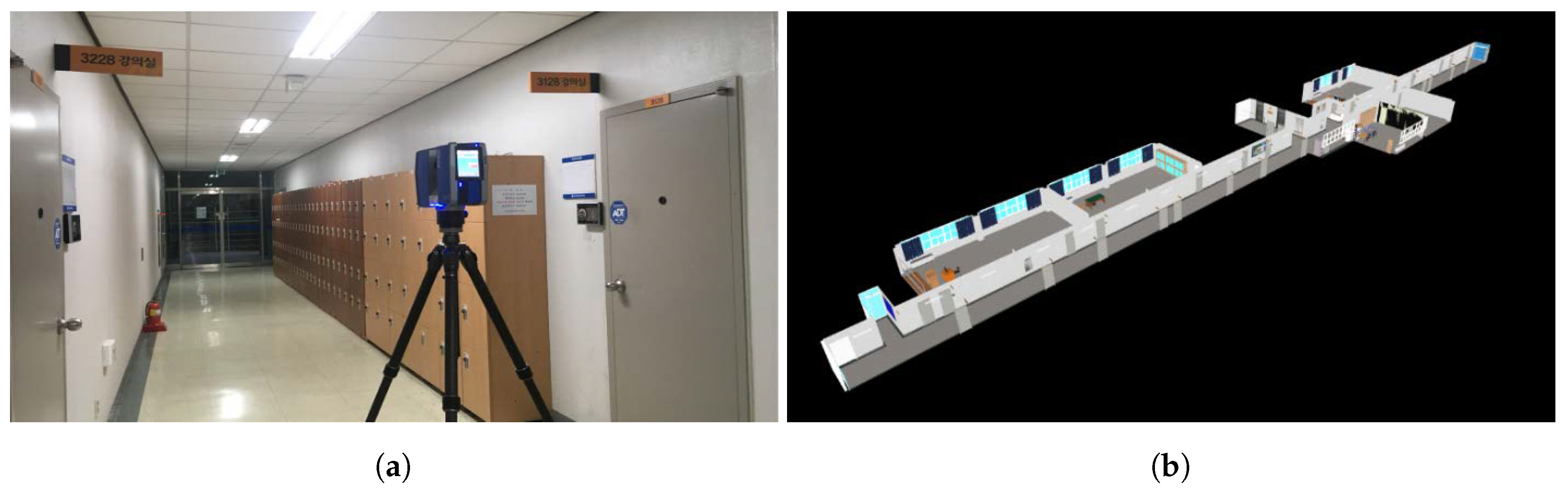
Experiments have been conducted in the 8th floor corridor and in the 3rd floor hall of the Department of IT Convergence Building at Chosun University, Korea. The dimensions of the corridor and the hall are 100 m × 2.25 m and 14 m × 6.5 m, respectively. For the design of smartphone applications, we collected 3D point cloud data using a 3D laser scanner (Faro Focus3D X 330) and created 3D indoor space maps as shown in Figure 11. Both testbeds for our experiments were equipped with BLE beacons and QR code markers are shown in Figure 12. The blue dots and red dots indicate the position of BLE beacons and QR markers, respectively. In this experiment, we deployed Estimote beacon devices based on the Bluetooth 4.0 Low Energy (BLE), and the beacon advertising packet interval was set to 300 ms and the transmission power was set to dBm. We collected the estimated position data while moving to the usual walking speed (≈1.3 m/s) in the testbed. Table 3 gives the details of the testbeds.
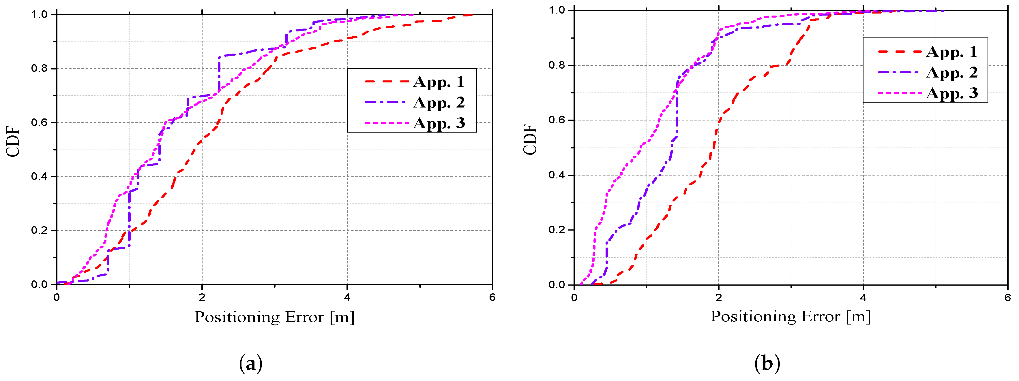
We verified the positioning accuracy of our hybrid IPS using experiments conducted in each testbed. First, we evaluate the cumulative distribution function (CDF) of position estimation error in three application types. In the experiments, we measured positioning at different locations 50 times in each testbed and constructed CDFs of the positioning errors for each application.
Figure 13 and Table 4 show the positioning error results of three types of different positioning combinations (App. 1–3) performed in each testbed. The App. 1 positioning method produces 54% and 58% for m) which is the probability that the positioning error is less than 2 m in the hall and corridor, respectively. However, in the App. 2 positioning method, the performance of the positioning accuracy is improved by the addition of geomagnetic field based positioning to the App. 1 positioning method. We observed that 70% and 90% m) are achieved at the hall and corridor, respectively. In the App. 3 positioning method using the smartphone camera, the positioning accuracy could also be improved using milliradian positioning. The results show 68% and 92% m) at each testbed. It is certain that the positioning accuracy could be improved based on the positioning methods used in App. 2 and 3. App. 1–3 showed average positioning errors of 1.82, 1.65, and 1.61 m at the hall testbed, and average errors of 1.44, 1.31, and 1.03 m at the corridor testbed. These results show that our smartphone indoor positioning system can choose a combination of positioning methods according to the required positioning accuracy and complexity level for each application.
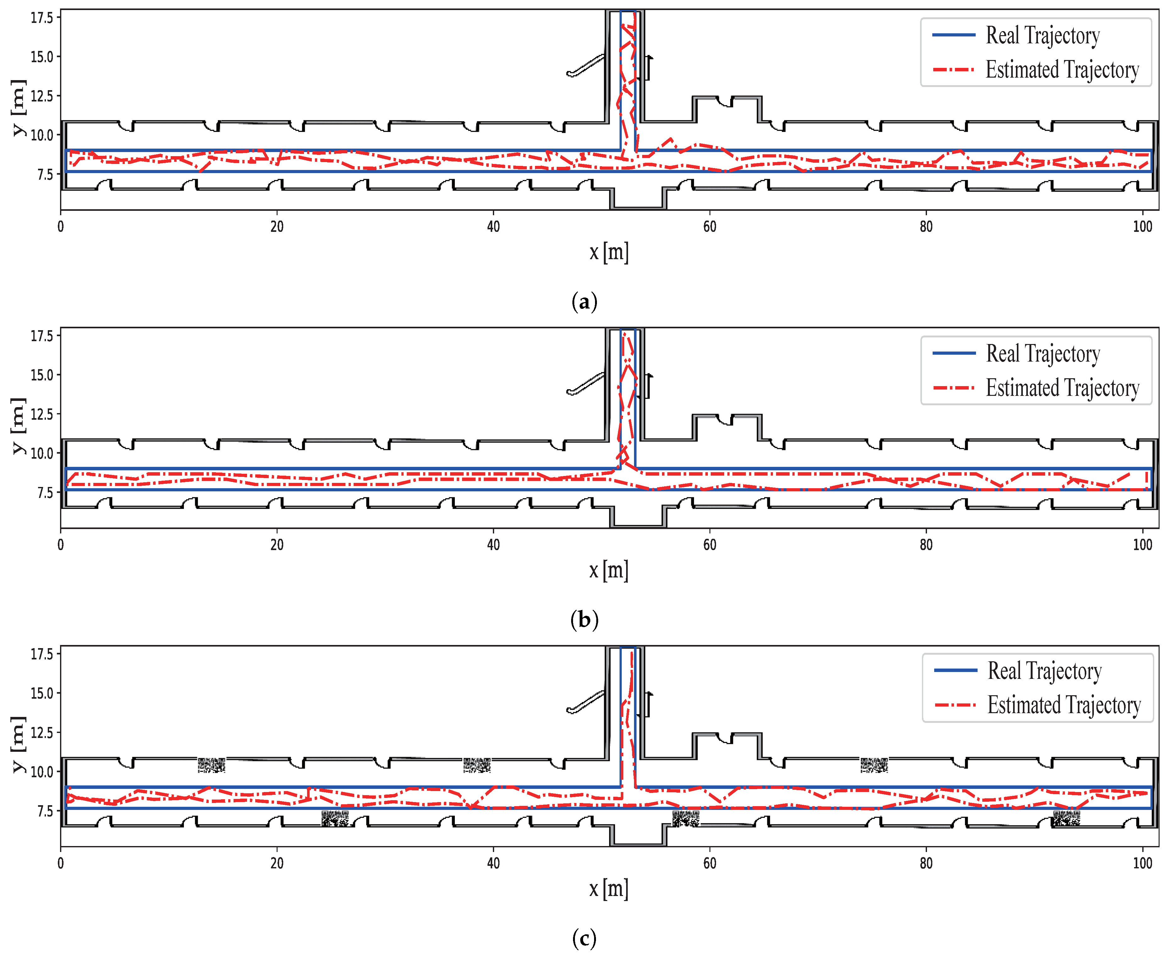
Next, we conducted another experiment to demonstrate the practical use of our positioning system for App. 1–3. In this experiment, the positioning data are recorded while a person moves in a designated path while holding an Android device. The real path that the person traversed and the estimated path are denoted with a blue line and a red dotted line as shown in Figure 14. Because the person walked freely inside the experiment area, the real path can be visually uneven compared to the estimated path.
From the figures, we can see that the estimated trajectory using the App. 2 positioning method is better than the estimated trajectory using the App. 1 method. Even though lower positioning performance is shown for the App. 2 positioning method, it will still be useful for App. 2 services such as pedestrian indoor navigation, path finding, and tracking. Also, from Figure 14c and Figure 15c, we can see that the estimated trajectory using the App. 3 positioning method has the best accuracy out of all three application methods. The milliradian positioning estimates the current location with the positioning accuracy shown in Table 2 from the QR marker and updates it to update the PDR position.
We classified three types of applications depending on the positioning accuracy and infrastructure features required for IPS. With estimated positions from each application method, the smartphone positioning system can be used for each target application. The application service examples (App. 1, App. 2, and App. 3) for which we developed our IPS (indoor navigation, indoor monitoring, and indoor AR services) are shown in Figure 16.
5. Conclusions
In this paper, we propose a smartphone-based IPS performing three types of applications (App. 1–3) using four different positioning methods and limited external infrastructure. In the App. 1 scenario, we use BLE beacons and IMU-based PDR to obtain a 4 m positioning error for social marketing services such as advertisement and indoor monitoring. In the App. 2 scenario, we added one more positioning method, geomagnetic field-based positioning, to those of App. 1 for navigation and tracking services. This combination of positioning methods achieves about 2 m positioning error. Finally, in the App. 3 scenario, the combination of BLE beacon, PDR, and milliradian positioning is used for indoor entertainment services such as VR and AR games. Specifically, a new proposed indoor positioning method, milliradian positioning using QR code markers, achieved high positioning accuracy of less than 2 m positioning error. In this paper, through indoor experimental results, we showed that the proposed IPS meets the positioning requirements for each application scenario and demonstrated examples of each application. We believe that the smartphone-based IPS presented here can become a practical system for increasing indoor service applications.
Author Contributions
Conceptualization, J.-Y.P.; Data curation, H.-S.G.; Project administration, H.-S.G.; Software, H.-S.G.; Supervision, J.-Y.P.; Validation, J.-Y.P.; Writing–original draft, H.-S.G.; Writing–review & editing, J.-Y.P.
Funding
This research received no external funding.
Conflicts of Interest
The authors declare no conflict of interest.
References
- Harle, R. A survey of indoor inertial positioning systems for pedestrians. IEEE Commun. Surv. Tutor. 2013, 15, 1281–1293. [Google Scholar] [CrossRef]
- Sakpere, W.; Adeyeye-Oshin, M.; Mlitwa, N.B. A State-of-the-Art Survey of Indoor Positioning and Navigation Systems and Technologies. S. Afr. Comput. J. 2017, 29, 145–197. [Google Scholar] [CrossRef]
- Deak, G.; Curran, K.; Condell, J. A survey of active and passive indoor localisation systems. Comput. Commun. 2012, 35, 1939–1954. [Google Scholar] [CrossRef]
- Li, X.; Pahlavan, K. Super-Resolution TOA Estimation with Diversity for Indoor Geolocation. IEEE Trans. Wirel. Commun. 2004, 3, 224–234. [Google Scholar] [CrossRef]
- Habaebi, M.H.; Khamis, R.O.; Zyoud, A.; Islam, M.R. RSS Based Localization Techniques for ZigBee Wireless Sensor Network. In Proceedings of the 2014 International Conference on Computer and Communication Engineering, Kuala Lumpur, Malaysia, 23–25 September 2014; pp. 72–75. [Google Scholar]
- Mahfouz, S.; Mourad-Chehade, F.; Honeine, P.; Farah, J.; Snoussi, H. Non-Parametric and Semi-Parametric RSSI/Distance Modeling for Target Tracking in Wireless Sensor Networks. IEEE Sens. 2016, 16, 2115–2126. [Google Scholar] [CrossRef] [Green Version]
- Xia, S.; Liu, Y.; Yuan, G.; Zhu, M.; Wang, Z. Indoor Fingerprint Positioning Based on Wi-Fi: An Overview. Int. J. Geo-Inf. 2017, 6, 135. [Google Scholar] [CrossRef]
- Ma, R.; Guo, Q.; Hu, C.; Xue, J. An improved WiFi indoor positioning algorithm by weighted fusion. Sensors 2015, 15, 21824–21843. [Google Scholar] [CrossRef]
- Wang, H.; Lenz, H.; Szabo, A.; Bamberger, J.; Hanebeck, U.D. WLAN-Based Pedestrian Tracking Using Particle Filters and Low-Cost MEMS Sensors. In Proceedings of the 2007 4th Workshop on Positioning, Navigation and Communication, Hannover, Germany, 22 March 2007; pp. 1–7. [Google Scholar]
- Renaudin, V.; Combettes, C. Magnetic, acceleration fields and gyroscope quaternion (MAGYQ)-based attitude estimation with smartphone sensors for indoor pedestrian navigation. Sensors 2014, 14, 22864–22890. [Google Scholar] [CrossRef]
- Jimenez, A.R.; Seco, F.; Zampella, F.; Prieto, J.C.; Guevara, J. PDR with a foot-mounted IMU and ramp detection. Sensors 2011, 11, 9393–9410. [Google Scholar] [CrossRef]
- Subbu, K.P.; Gozick, B.; Dantu, R. LocateMe: Magnetic-fields-based indoor localization using smartphones. ACM Trans. Intell. Syst. Technol. 2013, 4, 1–27. [Google Scholar] [CrossRef]
- Jang, H.J.; Shin, J.M.; Choi, L. Geomagnetic Field Based Indoor Localization Using Recurrent Neural Networks. In Proceedings of the 2017 IEEE Global Communications Conference (GLOBECOM), Singapore, 4–8 December 2017. [Google Scholar]
- Chen, G.; Meng, X.; Wang, Y.; Zhang, Y.; Tian, P.; Yang, H. Integrated WiFi/PDR/Smartphone Using an Unscented Kalman Filter Algorithm for 3D Indoor Localization. Sensors 2015, 15, 24595–24614. [Google Scholar] [CrossRef] [Green Version]
- Wu, Z.; Jedari, E.; Muscedere, R.; Rashidzadeh, R. Improved particle filter based on WLAN RSSI fingerprinting and smart sensors for indoor localization. Comput. Commun. 2016, 83, 64–71. [Google Scholar] [CrossRef]
- Chen, Z.; Zou, H.; Jiang, H.; Zhu, Q.; Soh, Y.; Xie, L. Fusion of WiFi, smartphone sensors and landmarks using the kalman filter for indoor localization. Sensors 2015, 15, 715–732. [Google Scholar] [CrossRef]
- Faragher, R.; Harle, R. Location Fingerprinting with Bluetooth Low Energy Beacons. Sel. Areas Commun. 2015, 33, 2418–2428. [Google Scholar] [CrossRef]
- Gozick, B.; Subbu, K.P.; Dantu, R.; Maeshiro, T. Magnetic maps for indoor navigation. IEEE Trans. Instrum. Meas. 2011, 60, 3883–3891. [Google Scholar] [CrossRef]
- Haverinen, J.; Kemppainen, A. Global indoor self-localization-based on the ambient magnetic field. Robot. Auton. Syst. 2009, 57, 1028–1035. [Google Scholar] [CrossRef]
- Nazemzadeh, P.; Fontanelli, D.; Macii, D.; Palopoli, L. Indoor Localization of Mobile Robots Through QR Code Detection and Dead Reckoning Data Fusion. IEEE/ASME Trans. Mechatron. 2017, 22, 2588–2599. [Google Scholar] [CrossRef]
- Ma, Y.; Soatto, S.; Kosecka, J.; Sastry, S.S. An Invitation to 3-D Vision: From Images to Geometric Models; Springer: New York, NY, USA, 2012; ISBN 978-0387008936. [Google Scholar]
- Woodman, O.; Harle, R. Pedestrian localisation for indoor environments. In Proceedings of the 10th International Conference on Ubiquitous Computing, Seoul, Korea, 21–24 September 2008; pp. 114–123. [Google Scholar]
- Klingbeil, L.; Wark, T. A Wireless Sensor Network for Real-Time Indoor Localisation and Motion Monitoring. In Proceedings of the International Conference on Information Processing in Sensor Networks (IPSN 2008), St. Louis, MO, USA, 22–24 April 2008; pp. 39–50. [Google Scholar]
- Foxlin, E. Pedestrian Tracking with Shoe-Mounted Inertial Sensors. Comput. Graph. Appl. 2005, 25, 38–46. [Google Scholar] [CrossRef]
- Lee, S.W.; Mase, K. Recognition of walking behaviors for pedestrian navigation. In Proceedings of the 2001 IEEE International Conference on Control Applications (CCA’01), Mexico City, Mexico, 7 September 2001; pp. 1152–1155. [Google Scholar]
- Zeng, Q.; Wang, J.; Meng, Q.; Zhang, X.; Zeng, S. Seamless Pedestrian Navigation Methodology Optimized for Indoor/Outdoor Detection. IEEE Sens. 2018, 18, 363–374. [Google Scholar] [CrossRef]
- Zhuang, Y.; El-Sheimy, N. Tightly-Coupled Integration of WiFi and MEMS Sensors on Handheld Devices for Indoor Pedestrian Navigation. IEEE Sens. 2016, 16, 224–234. [Google Scholar] [CrossRef]
- Lee, S.; Kim, B.; Kim, H.; Ha, R.; Cha, H. Inertial Sensor-Based Indoor Pedestrian Localization with Minimum 802.15.4a Configuration. IEEE Trans. Ind. Inform. 2011, 7, 455–466. [Google Scholar] [CrossRef]
- Liu, H.H.; Liu, C. Implementation of Wi-Fi signal sampling on an android smartphone for indoor positioning systems. Sensors 2018, 18, 3. [Google Scholar] [CrossRef]
- Tong, X.; Liu, K.; Tian, X.; Fu, L.; Wang, X. Fineloc: A fine-grained self-calibrating wireless indoor localization system. IEEE Trans. Mob. Comput. 2018, 18, 2077–2090. [Google Scholar] [CrossRef]
- Santosh, S.; Hui-Seon, G.; Nak-Yong, K.; Suk-Seung, H.; Jae-Young, P. Improving Indoor Fingerprinting Positioning with Affinity Propagation Clustering and Weighted Centroid Fingerprint. IEEE Access 2019, 7, 31738–31750. [Google Scholar] [CrossRef]
- Amirisoori, S.; Daud, S.M.; Ahmad, N.A.; Aziz, N.S.N.A.; Sa’at, N.I.M.; Noor, N.Q.M. WI-FI Based Indoor Positioning Using Fingerprinting Methods (KNN Algorithm) in Real Environment. Future Gener. Commun. Netw. 2017, 10, 23–36. [Google Scholar] [CrossRef]
- Wang, Q.; Sun, R.; Zhang, X.; Sun, Y.; Lu, X. Bluetooth positioning-based on weighted K-nearest neighbors and adaptive bandwidth mean shift. Distrib. Sens. Netw. 2017, 13, 1–8. [Google Scholar] [CrossRef]
- Yadav, R.K.; Bhattarai, B.; Gang, H.S.; Pyun, J.Y. Trusted K Nearest Bayesian Estimation for Indoor Positioning System. IEEE Access 2019, 7, 51484–51498. [Google Scholar] [CrossRef]
- Jimenez, A.R.; Seco, F.; Prieto, C.; Guevara, J. A comparison of Pedestrian Dead-Reckoning algorithms using a low-cost MEMS IMU. In Proceedings of the IEEE International Symposium on Intelligent Signal Processing, Budapest, Hungary, 26–28 August 2009; pp. 37–42. [Google Scholar]
- Misra, P.; Enge, P. Global Positioning System: Signals, Measurements and Performance, 2nd ed.; Ganga-Jamuna Press: Lincoln, MA, USA, 2010; ISBN 978-0970954428. [Google Scholar]
- Chung, J.; Donahoe, M.; Schmandt, C.; Kim, I.J.; Razavai, P.; Wiseman, M. Indoor Location Sensing Using Geo-magnetism. In Proceedings of the 9th International Conference on Mobile Systems, Applications, and Services, Bethesda, MD, USA, 28 June–1 July 2011; pp. 141–154. [Google Scholar]
- Basiri, A.; Amirian, P.; Winstanley, A. The Use of Quick Response (QR) Codes in Landmark-Based Pedestrian Navigation. Navig. Obs. 2014, 2014, 1–7. [Google Scholar] [CrossRef] [Green Version]
- Google. ZXing. Available online: https://opensource.google.com/projects/zxing (accessed on 8 August 2019).
Figure 1.
Operation procedure of the proposed indoor positioning system.

Figure 2.
RSSI simulations and observations.

Figure 3.
Data structure for the beacon fingerprint map.

Figure 4.
Example of a BLE beacon identifier used in the proposed indoor positioning system.

Figure 5.
Milliradian measurement using observation equipment.

Figure 6.
QR code marker and milliradian measurement. (The center coordinates of the locator symbols are marked in green.)
Figure 6.
QR code marker and milliradian measurement. (The center coordinates of the locator symbols are marked in green.)

Figure 7.
Estimation of current smartphone position using QR code.

Figure 8.
Flow chart of hybrid positioning application (App. 1) using BLE beacon and PDR.

Figure 9.
Flow chart of hybrid positioning algorithm (App. 2) using BLE beacon, magnetic field, and PDR.
Figure 9.
Flow chart of hybrid positioning algorithm (App. 2) using BLE beacon, magnetic field, and PDR.

Figure 10.
Flow chart of hybrid positioning algorithm (App. 3) using BLE beacon, PDR, and marker detection.
Figure 10.
Flow chart of hybrid positioning algorithm (App. 3) using BLE beacon, PDR, and marker detection.

Figure 11.
3D indoor space map. (a) Indoor scanning to build the 3D map. (b) Sample of rendered 3D indoor map.
Figure 11.
3D indoor space map. (a) Indoor scanning to build the 3D map. (b) Sample of rendered 3D indoor map.

Figure 12.
Experiment testbeds equipped with BLE beacons and QR marker. (a) Hall of 3rd floor. (b) Corridor of the 8th floor.
Figure 12.
Experiment testbeds equipped with BLE beacons and QR marker. (a) Hall of 3rd floor. (b) Corridor of the 8th floor.

Figure 13.
CDF of positioning error for each application. (a) Positioning error in the hall. (b) Positioning error in the corridor.
Figure 13.
CDF of positioning error for each application. (a) Positioning error in the hall. (b) Positioning error in the corridor.

Figure 14.
Estimation of moving trajectory in the corridor. (a) Moving trajectory of user measured with App. 1. (b) Moving trajectory of user measured with App. 2. (c) Moving trajectory of user measured with App. 3.
Figure 14.
Estimation of moving trajectory in the corridor. (a) Moving trajectory of user measured with App. 1. (b) Moving trajectory of user measured with App. 2. (c) Moving trajectory of user measured with App. 3.

Figure 15.
Estimation of moving trajectory in the hall. (a) Moving trajectory of user measured with App. 1. (b) Moving trajectory of user measured with App. 2. (c) Moving trajectory of user measured with App. 3.
Figure 15.
Estimation of moving trajectory in the hall. (a) Moving trajectory of user measured with App. 1. (b) Moving trajectory of user measured with App. 2. (c) Moving trajectory of user measured with App. 3.

Figure 16.
Indoor location-based services. (a) Indoor navigation service. (b) AR mode indoor navigation service. (c) Indoor monitoring service (people tracking). (d) Providing statistical data (people counting).
Figure 16.
Indoor location-based services. (a) Indoor navigation service. (b) AR mode indoor navigation service. (c) Indoor monitoring service (people tracking). (d) Providing statistical data (people counting).


Table 1.
LBS application, and required features, and used technologies.
| LBS Category | Application Examples | Requirements | Positioning Technologies |
|---|---|---|---|
| Marketing | social marketing, | approx. accuracy = 2∼4 m | Bluetooth, PDR |
| (App.1) | advertisement, indoor monitoring | ||
| Navigation and Tracking | pedestrian navigation, | approx. accuracy = 1.5∼3 m | Bluetooth, PDR |
| (App.2) | path finding, tracking | geomagnetic field | |
| Entertainment | social networking, | approx. accuracy = 1.5∼3 m, | Bluetooth, PDR |
| (App.3) | gaming, fun sharing | camera for AR service | Camera |
Table 2.
Measured distance from smartphone to marker using milliradian measurement.
| (m) (A) | (m) (B) | Error (|A−B|) | (m) (A) | (m) (B) | Error (|A−B|) |
|---|---|---|---|---|---|
| 1 | 1.00 | 0.00 | 6 | 6.12 | 0.12 |
| 2 | 2.02 | 0.02 | 7 | 7.05 | 0.05 |
| 3 | 3.04 | 0.04 | 8 | 8.04 | 0.04 |
| 4 | 3.99 | −0.01 | 9 | 9.09 | 0.09 |
| 5 | 5.04 | 0.04 | 10 | 10.08 | 0.08 |
Table 3.
Experimental conditions of testbeds.
| Number of BLE Beacons | Number of Reference Points | Distance between Beacons (m) | Distance between Reference Points (m) | Area (m) | |
|---|---|---|---|---|---|
| Hall | 6 | 35 | 6.75 | 1.8 | 225 |
| Corridor | 35 | 125 | 6.75 | 1.8 | 91 |
Table 4.
Positioning accuracy of the proposed IPS for each application.
| Mode | Testbeds | m) | m) | Average Error [m] | Standard Deviation |
|---|---|---|---|---|---|
| App. 1 | Hall | 0.96 | 0.54 | 1.82 | 1.191 |
| Corridor | 0.99 | 0.58 | 1.44 | 0.705 | |
| App. 2 | Hall | 0.98 | 0.70 | 1.65 | 0.891 |
| Corridor | 0.99 | 0.90 | 1.31 | 0.734 | |
| App. 3 | Hall | 0.97 | 0.68 | 1.61 | 1.051 |
| Corridor | 0.99 | 0.92 | 1.03 | 0.740 |
© 2019 by the authors. Licensee MDPI, Basel, Switzerland. This article is an open access article distributed under the terms and conditions of the Creative Commons Attribution (CC BY) license (http://creativecommons.org/licenses/by/4.0/).
Share and Cite
MDPI and ACS Style
Gang, H.-S.; Pyun, J.-Y. A Smartphone Indoor Positioning System Using Hybrid Localization Technology. Energies 2019, 12, 3702. https://doi.org/10.3390/en12193702
AMA Style
Gang H-S, Pyun J-Y. A Smartphone Indoor Positioning System Using Hybrid Localization Technology. Energies. 2019; 12(19):3702. https://doi.org/10.3390/en12193702
Chicago/Turabian StyleGang, Hui-Seon, and Jae-Young Pyun. 2019. "A Smartphone Indoor Positioning System Using Hybrid Localization Technology" Energies 12, no. 19: 3702. https://doi.org/10.3390/en12193702
Note that from the first issue of 2016, this journal uses article numbers instead of page numbers. See further details here.