Article

Effect of the Hole Diameter in Mechanical Properties of Wood: Experimental and Numerical Approaches

1
Post-Graduate Program in Materials Science and Engineering, Technological Development Center, Federal University of Pelotas, Pelotas 96010-610, Brazil
2
Post-Graduate Program in Mining, Metallurgical and Materials Engineering, Federal University of Rio Grande do Sul, Porto Alegre 91540-000, Brazil
3
Post-Graduate Program in Materials Science and Engineering—PIPE, Federal University of Paraná, Curitiba 81531-980, Brazil
4
Group on Mechanics of Materials and Structures, Cachoeira do Sul Campus, Federal University of Santa Maria, Santa Maria 96503-205, Brazil
*
Author to whom correspondence should be addressed.
Forests 2024, 15(4), 722; https://doi.org/10.3390/f15040722
Submission received: 21 February 2024 / Revised: 12 April 2024 / Accepted: 16 April 2024 / Published: 19 April 2024
(This article belongs to the Special Issue Advances in the Study of Wood Mechanical and Physical Properties)

Abstract

:
Introducing openings or holes into wooden structures is a common practice for providing utility services. However, this practice leads to stress concentration, resulting in a reduction in stiffness and load-carrying capacity. Therefore, understanding the effects of holes on beam properties is important for design considerations. This study investigates the mechanical behavior of a wooden beam made from juvenile Pinus elliottii containing open cylindrical holes with three different diameters: 4, 8, and 12 mm. The mechanical properties were evaluated for compression parallel to the fibers, quasi-static bending, and tension perpendicular to the fibers. Numerical simulations were conducted using a finite element (FE) model, considering the orthotropic elastic properties determined from experimental tests and elastic ratios reported in the literature. The experimental results indicated that the influence of hole diameter was not significant on the compressive properties; however, longitudinal crack failures began to form for holes with diameters of 8–12 mm. Regardless of hole size, the compressive and bending characteristics revealed that hole location did not affect the stiffness, strength, or damage mechanisms.

1. Introduction

Wood is a sustainable structural material that offers numerous advantages, such as low cost, excellent thermal insulation properties, and a high strength-to-weight ratio when compared to other building materials [1]. In fact, wood is known as a highly versatile material that provides flexibility in design and processes. Solid woods have historically been widely used for numerous industrial applications, including building construction and furniture. With advancements in design criteria and techniques, wood has emerged as an interesting material with improved performance, aesthetic features, and durability [2].
Notches, openings, and holes are common in wooden structural elements, such as beams and columns, to provide building services. This leads to stress concentration around the openings, which elevates the maximum stress levels compared to bodies without holes. Therefore, a hole in the geometry of a structural material reduces the overall mechanical strength, making it necessary to study its behavior under these circumstances [3]. Accordingly, the effect of holes in wooden structures has been reported in the literature. Both hole diameter and location have a significant effect on mechanical characteristics [4].
Yoshihara and Maruta [4] determined the tensile and shear modulus of spruce using a non-destructive method and reported that the nominal elastic moduli often decrease as the size of the open hole increases. In this study, the hole was located close to the mid-length of the specimen. Reiner et al. [5] investigated thin quasi-isotropic beech veneer laminates subjected to various mechanical tests derived from fiber-reinforced counterparts. Their findings revealed consistent strength and damage resistance values compared to fiber-reinforced laminates, albeit at lower magnitudes. Mousavi and Gandomi et al. [6] addressed the challenge of damage detection in wood materials using machine learning algorithms. They focused on classifying hole defects in common wood types, such as hard (merbau) and soft (pine) wood, through contact ultrasonic tests, achieving high classification accuracy. This approach contributes to improved non-destructive testing in wood materials. Chen et al. [7] explored the impact of web openings in oriented strand board (OSB) webbed laminated bamboo lumber (LBL) box-shaped joists. They observed that smaller circular holes had negligible effects on strength and stiffness, while larger holes resulted in strength reductions, especially for unreinforced joists. Reinforcing methods, including collar-shaped oriented strand board patches (C-OSBs) and collar-shaped steel patches (C-SPs), effectively improved the mechanical performance of joists with web openings. These findings contribute to the understanding of structural integrity in engineered wood products.
In summary, the combination of these studies presents a comprehensive overview of recent advancements in the mechanical characterization, damage detection, and structural reinforcement of wood materials, contributing to the state-of-the-art knowledge in the field. Although the study of open holes in solid wood has advanced in recent years, the current analyses of open holes in wood are quite conservative and are not sufficient compared to those available for composite laminates. Therefore, an in-depth parametric study can provide more information on the behavior of beams with stress concentration. Consequently, numerical simulation can be an effective tool to examine the mechanical behavior of structural elements with stress concentration locations [8].
Wood, as an orthotropic material, exhibits distinct mechanical properties in different directions relative to the fibers, with greater strength in the direction parallel to the fibers due to the alignment of cellulose chains. The theory of elasticity applied to wood assumes three mutually perpendicular planes with elastic symmetry, reflecting its internal structure [9]. Finite element analysis has been used to assess the mechanical behavior of wood, with different approaches for modeling, including cellular models, homogenization-based models, and laminated models [10]. Three-dimensional (3D) modeling is preferable to better reflect the mechanical properties of wood, as it can more accurately capture stress distributions [11]. However, some studies still use 2D modeling, which can result in the overestimation or underestimation of stresses in different planes [12]. The choice of the appropriate model depends on the objective and complexity of the analysis [13].
In this study, experimental and numerical analyses were conducted to ascertain the influence of different hole diameters on the compressive, bending, and tensile properties of pine wood. The compressive test was used to analyze the effects of hole diameter and calibrate the numerical model. Then, three-point bending and tensile tests were conducted to investigate the stress concentration around the hole region. Instead of delving into the entirety of wood’s mechanical behavior or failure mechanisms, this study provides valuable insights into the specific aspect of stress concentration induced by anisotropic effects in wood due to the presence of holes.

2. Materials and Methods

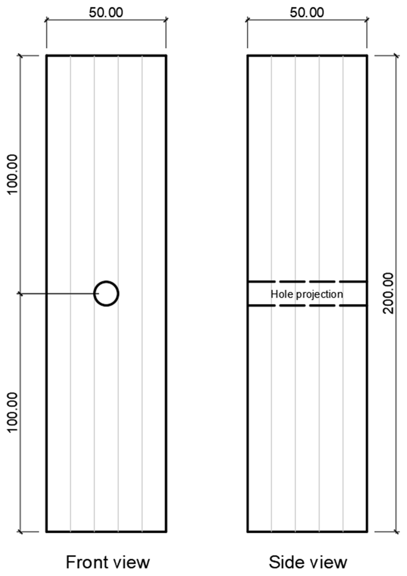
2.1. Material Selection and Sampling

Air-dried Pinus elliottii lumbers from juvenile trees (10–20 years old) located in southern Brazil were sourced from a sawmill. To achieve dimensional stability, the dried lumbers were conditioned in a climatic chamber for three months at a temperature of 20 °C and a relative humidity of 65%, as specified by ASTM D143 [14].
The apparent density of five prismatic samples was measured using an analytical scale (0.001 g resolution) and a digital caliper (0.01 mm resolution). Samples were categorized into four groups: the control group without any holes (WT group) and three groups with holes of diameters 4, 8, and 12 mm. Efforts were made to maintain similar densities for each group. The mean apparent densities of the four groups were 0.363, 0.373, 0.377, and 0.363 g/cm3, respectively, confirming their high similarity in terms of density. The standard deviations ranged from 0.041 to 0.043 g/cm3. This density-based homogenization approach was adopted for all the experimental tests. These values are relatively lower than some reported results (around 0.50 g/cm3) for pine woods planted in southern Brazil [15]. Wood density can vary due to factors such as forest location, local climate [16], harvesting [17], and storage [18]. Holes were drilled in the tangential plane of the samples using steel drills suitable for woodworking at 1000 rpm, coupled to a Ferrari FG-12 bench drill with a nominal power of 350 W.

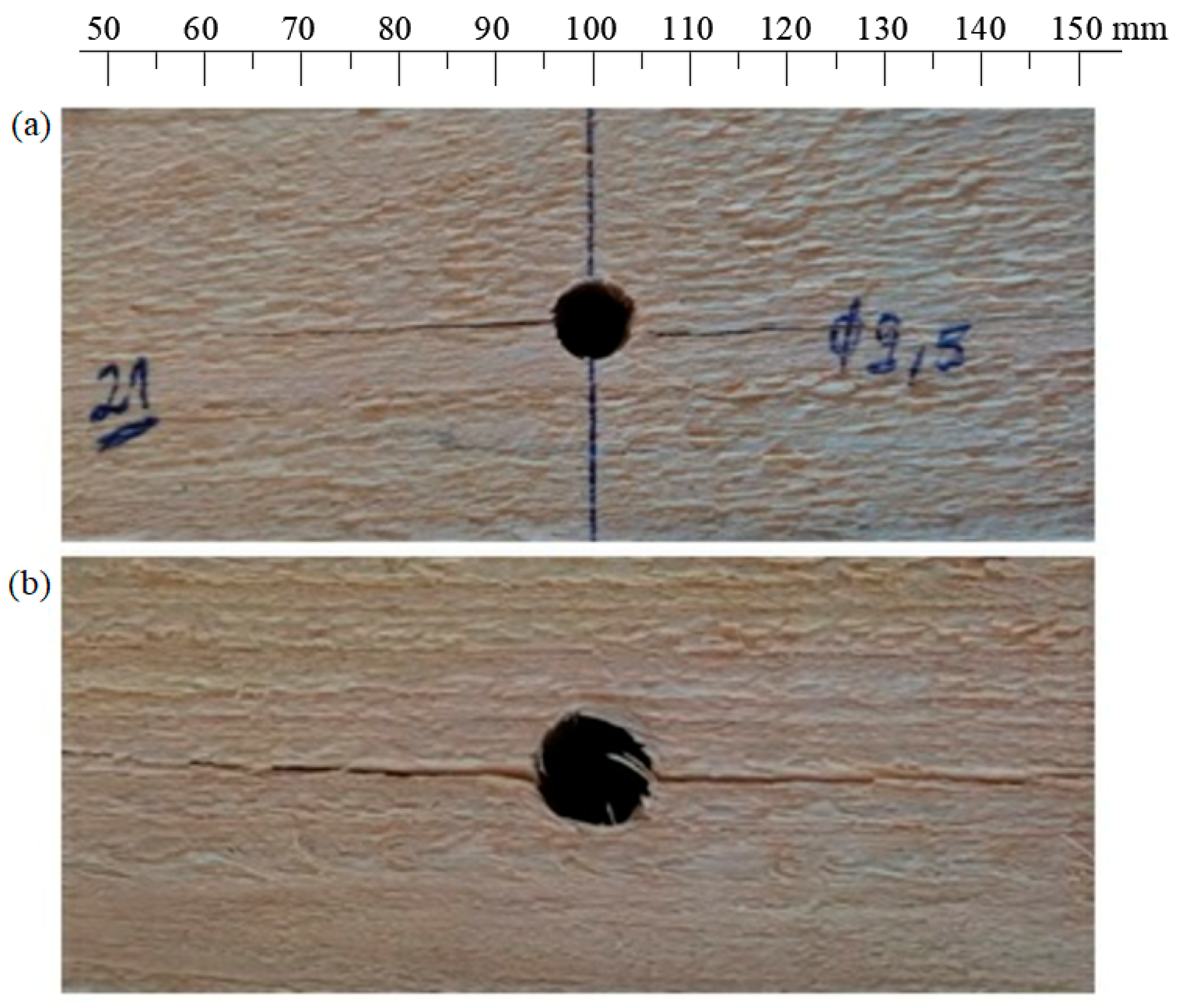
2.2. Mechanical Tests

For the compression test parallel to the fibers, where wood exhibits higher strength and stiffness, 11 samples from each group with dimensions of 50 × 50 × 200 mm (longest dimension in the longitudinal direction) were prepared according to ASTM D143 [14] (Figure 1). The tests were conducted using an EMIC DL3000 universal testing machine at a displacement rate of 0.8 mm/min, adapted from the standard rate of 0.6 mm/min. A central 100 mm extensometer was used to measure longitudinal deformation. The holes in these specimens were positioned at the center of their tangential planes.
Quasi-static bending tests were performed on samples measuring 50 × 50 × 760 mm (longest dimension in the longitudinal direction), following ASTM D143 [14]. The holes were drilled between the indenter and one of the side supports, as this region experiences maximum transverse shear stress (Figure 2). Nine samples were tested for each group at a constant speed of 2.5 mm/min using the aforementioned testing machine.
The tension perpendicular to the grain samples were cut with external dimensions of 50 mm × 50 mm × 63 mm (longest dimension in the tangential direction), according to ASTM D143 [14] (Figure 3). Two semicircular notches (diameter 26 mm) were machined at the gripping region of the samples to apply load at a speed of 2.5 mm/min. The holes were drilled at the geometric center of the tangential planes. Ten specimens were tested for each group.

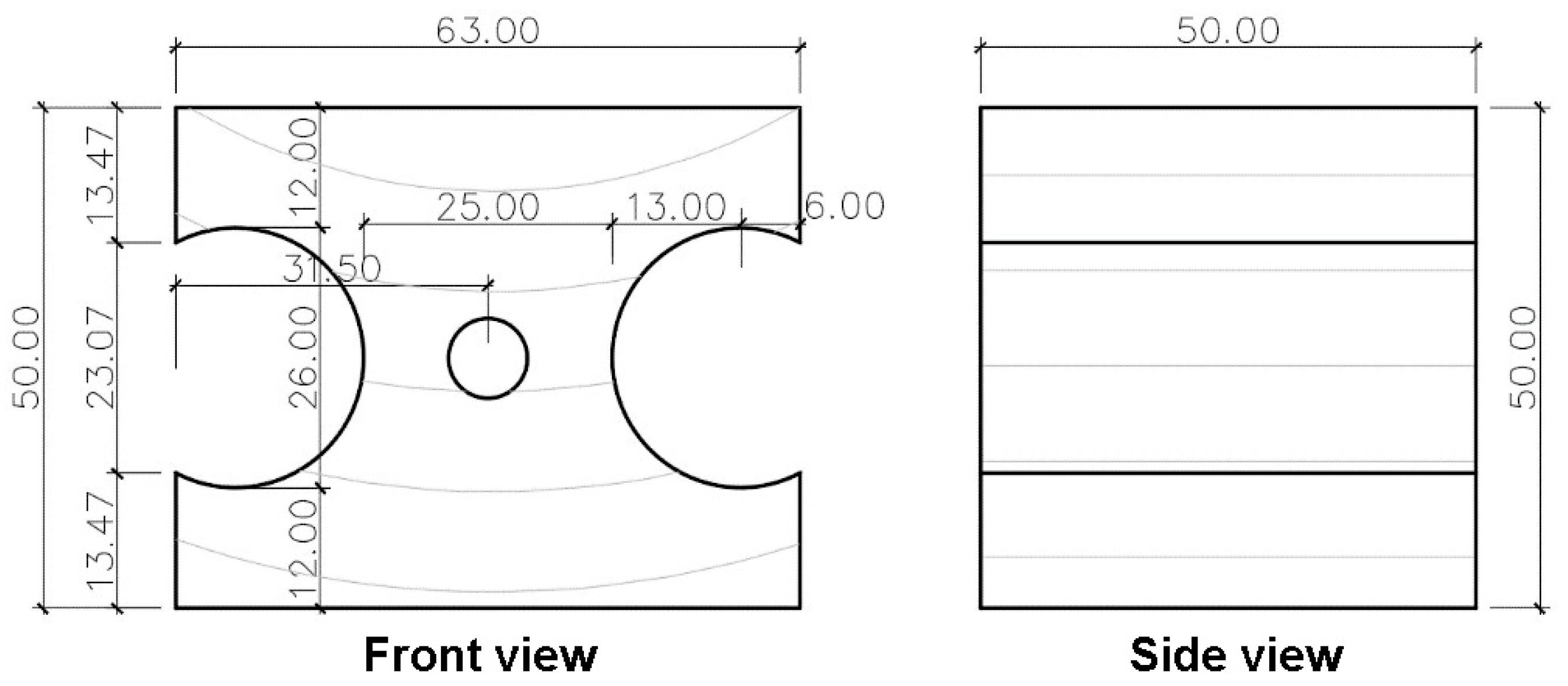
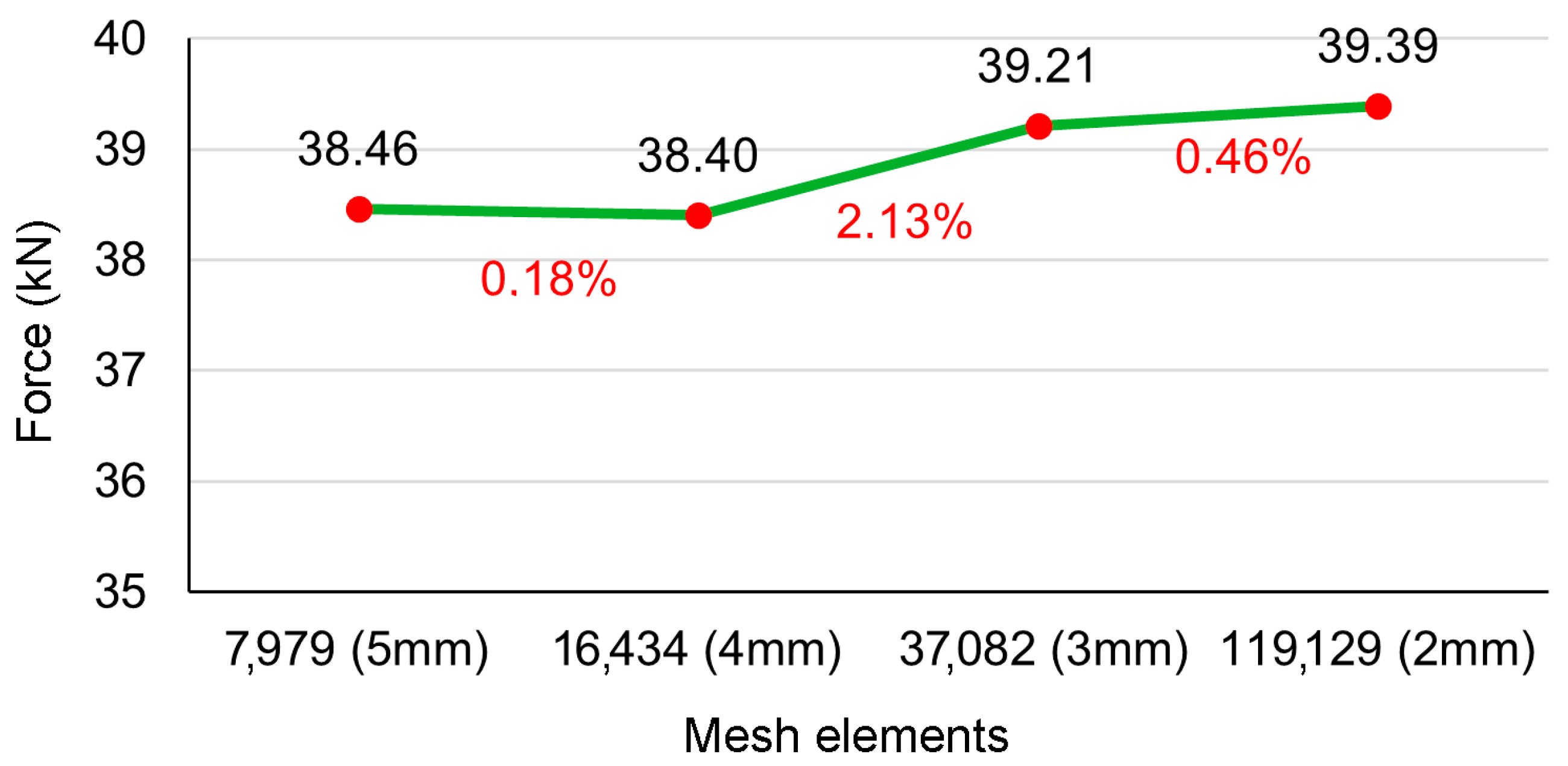
2.3. Finite Element (FE) Model

To investigate the effect of the holes on the stress concentrations in the wood samples, a numerical study based on the finite element method (FEM) was conducted for compression parallel to the grain and static bending tests. The longitudinal elastic modulus ( E 1 ) was experimentally determined through the aforementioned compression parallel to the grain tests, yielding an average value of 6848 MPa for the control group. These data were used to calculate the properties shown in Table 1 using elastic ratios provided by the Forest Products Laboratory [19].
To account for the orthotropic nature of wood, the stiffness matrix D shown in Table 2 was incorporated into the FE model using AbaqusTM/Standard v. 6.14 software. The geometry of the samples and test devices was designed in the software to simulate the tests, wherein a three-dimensional model was implemented for each group based on the different hole diameters.
Considering that the L, T, and R directions are, respectively, the 1, 2, and 3 directions, the stress–strain relationships of a orthotropic elastic material can be expressed as [20]:
σ 11 σ 22 σ 33 σ 12 σ 13 σ 23 = D 1111 D 1122 D 1133 0 0 0 D 1122 D 2222 D 2233 0 0 0 D 1133 D 2233 D 3333 0 0 0 0 0 0 D 1212 0 0 0 0 0 0 D 1313 0 0 0 0 0 0 D 2323 ε 11 ε 22 ε 33 γ 12 γ 13 γ 23 = D e l ε 11 ε 22 ε 33 γ 12 γ 13 γ 23
where the engineering constants for matrix D are defined as:
D 1111 = E 1 1 v 23 v 32 ϒ
D 2222 = E 2 1 v 13 v 31 ϒ
D 3333 = E 3 1 v 12 v 21 ϒ
D 1122 = E 1 v 21 + v 31 v 23 ϒ = E 2 v 12 + v 32 v 13 ϒ
D 1133 = E 1 v 31 + v 21 v 32 ϒ = E 3 v 13 + v 12 v 23 ϒ
D 2233 = E 2 v 32 + v 12 v 31 ϒ = E 3 v 23 + v 21 v 13 ϒ
D 1212 = G 12
D 1313 = G 13
D 2323 = G 23
ϒ = 1 1 v 12 v 21 v 23 v 32 v 13 v 31 2 v 21 v 32 v 13
The FE model depicted in Figure 4 was developed to analyze the wood samples under compression parallel to the grain (Figure 4a), bending (Figure 4b), and tensile perpendicular to the grain (Figure 4c) conditions. To simulate the wood’s orthotropy related to the arrangement of its growth rings, a local cylindrical coordinate system was established. Directions 1, 2, and 3 represented the longitudinal, tangential, and radial directions, respectively. For the compressive loading, direction 1 was aligned with the force directions (y direction), while for the bending and tensile conditions, direction 1 was perpendicular to the force direction. To simplify the numerical model, frictionless contact conditions between the wood and test devices were assumed.
To assess stiffness and stress using the FE model, rigid body constraints from a reference point (RP) were applied to simulate the test devices. For compressive loading, boundary conditions were established allowing a 0.45 mm displacement on the upper device relative to an RP positioned at the same location, based on experimental test values. Additionally, neither displacement nor rotation were permitted on the RP of the lower device (Ux = Uy = Uz = Urx = Ury = Urz = 0).
The bending test was simulated considering symmetry along the x-axis, simulating only half of the sample. For this, two RPs were created: the first served as the indenter, applying a 10 mm displacement on the upper device, while the second served as the support, allowing neither displacement nor rotation (Ux = Uy = Uz = Urx = Ury = Urz = 0). To ensure symmetry, displacements along the x-axis and rotation in the y- and z-axes (Ux = Ury = Urz = 0) were set to zero.
Regarding the tension perpendicular to the grain condition, neither displacement nor rotation were allowed on the RP of the lower device (Ux = Uy = Uz = Urx = Ury = Urz = 0), and a 1.5 mm displacement was applied to the upper device in the y direction, based on experimental tests.
A three-dimensional (3D) mesh consisting of 8-node linear brick elements with reduced integration (C3D8R type) was employed. The results of the maximum reaction force in bending for a 10 mm displacement, along with various mesh sizes (ranging from 5.0 mm to 2.0 mm), were analyzed to refine the mesh until achieving a difference below 5% in reaction force compared to the previous mesh. The largest difference, 2.1%, was observed between the 4 mm and 3 mm meshes. Based on the convergence plot (Figure 5), a 2 mm mesh was selected.

2.4. Statistical Analysis of Experimental Data

To use the experimentally obtained data as inputs for the numerical models, outliers, identified using the interquartile range (IQR) method, were excluded. The resulting dataset was tested for normality (Shapiro–Wilk test) and homogeneity of variances (Levene’s test) before applying one-way analysis of variance (ANOVA). When the null hypothesis was rejected, means were compared using Tukey’s honestly significant difference (HSD) test at a 1% significance level. All the analyses were conducted using Statgraphics Centurion® v18 software.

3. Results and Discussion

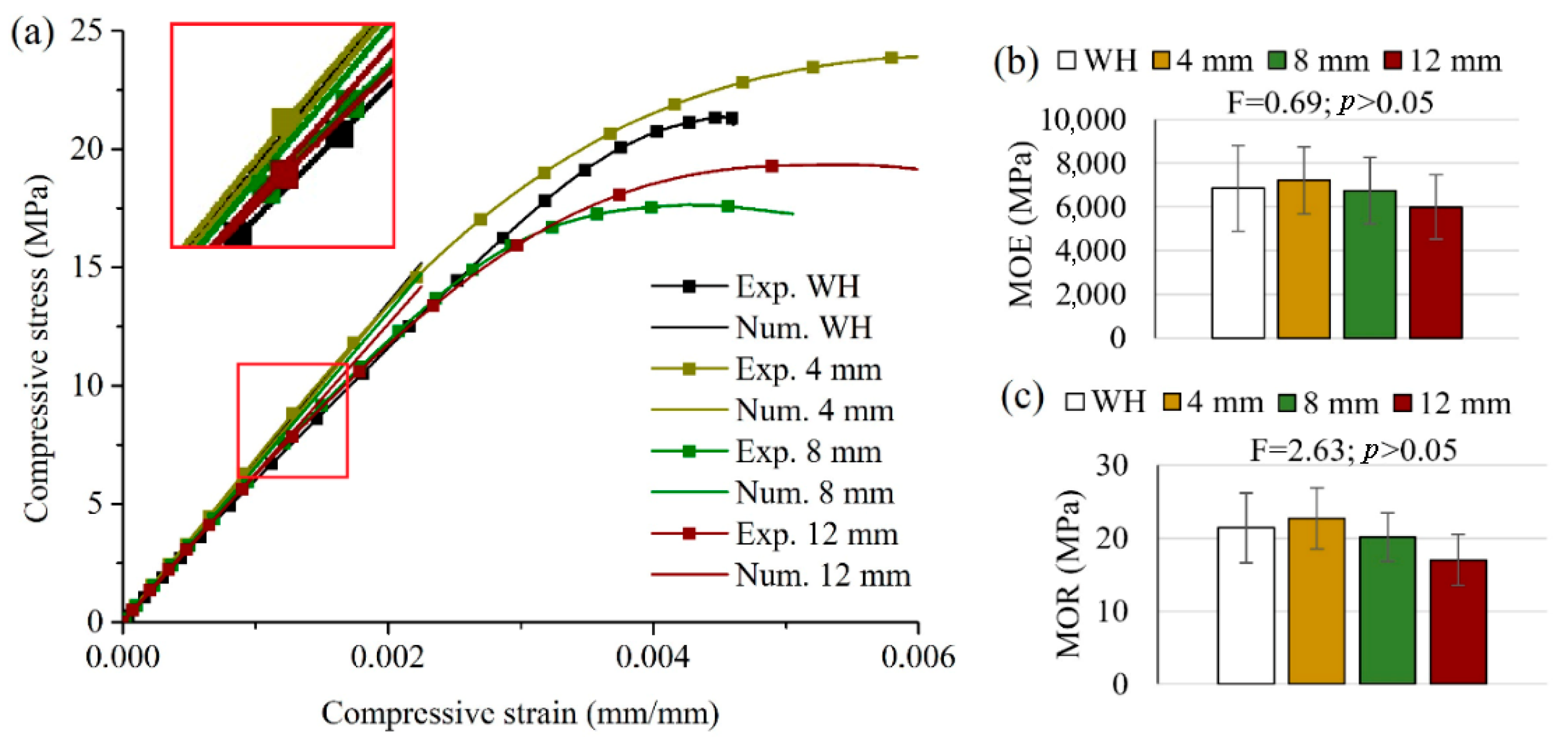
3.1. Compression Parallel to Grain

Compression tests were employed to calibrate the numerical models under study. Figure 6a presents the compressive behaviors delineated by the stress versus deformation curves obtained from both the experimental and numerical analyses. While the experimental curves represent the median values, the numerical curves were derived from finite element method (FEM) AbaqusTM/Standard v. 6.14 software. Substantial agreement between the experimental and numerical curves, especially in the elastic phase, was observed across all the cases.
It is important to recognize the study’s limitation in employing a linear model to depict wood behavior. Although this approach enabled a focus on the anisotropic effects around the holes, it falls short of capturing wood’s nonlinear behavior, particularly under extreme loading conditions. Subsequent research could delve into advanced material models to enhance our comprehension of wood behavior.
Figure 6b illustrates the modulus of elasticity (MOE) for both the drilled and undrilled samples. While no statistical significance was discerned between the groups, a declining trend was evident as the hole diameter expanded, with samples featuring a 12 mm hole registering the lowest value. Generally, the MOE values ranged between 6000 and 7000 MPa, surpassing the 5250 MPa MOE reported by Acosta et al. [21] for similar pine woods. This discrepancy can be attributed to differing sample dimensions: Acosta et al. [21] examined woods measuring 2.5 × 2.5 × 10 cm3, whereas our study employed 5 × 5 × 20 cm3 samples. The larger sample dimensions in our study likely led to longer stress propagation paths and more intricate interactions between the wood fibers and structural elements. This enlarged sample size facilitates a more accurate assessment of material mechanical behavior under applied loads, encompassing a broader spectrum of stress distribution patterns. Conversely, Acosta et al.’s [21] smaller samples may display varied stress propagation characteristics, potentially resulting in disparate observed mechanical properties. Additionally, the observed variability in these results may stem from intrinsic wood factors such as density, growth ring orientation, and structural defects [22].
Similar trends were observed for compressive strength (Figure 6c), with the 12 mm hole samples exhibiting an approximately 15% decline compared to the control group. However, no statistically significant difference was calculated across any group. The recorded values fell within the 16–23 MPa range, which is 32% and 46% lower than the 50 MPa compressive strength reported by Acosta et al. [21]. This reduced value compared to the literature might be attributed to the lower density levels observed in our study.
In the compression tests parallel to the grain, the samples from the control and 4 mm groups showed no discernible damage. In contrast, longitudinal cracks were evident in the 8 mm and 12 mm hole samples, as depicted in Figure 7. Moreover, the failures predominantly originated from the hole, with the 12 mm hole samples displaying longer cracks than their 8 mm counterparts.
Figure 8 presents the numerical simulation results concerning the stress field when the samples underwent compression parallel to the grain. Figure 8a,b depict the normal and shear stress fields around the hole, respectively. The pronounced stress concentration around the holes becomes more evident with an increase in hole diameter, leading to longer cracks. Additionally, the regions of concentrated shear stresses in the transverse direction expand as the holes are enlarged.
It is important to highlight that our study did not integrate a failure mechanism within the finite element simulation. Our focus centered on exploring the anisotropic effects on stress concentrations around holes in wood samples rather than specific failure mechanisms. Consequently, the absence of a failure mechanism in the current model should be considered a limitation.
In a similar study, Tang et al. [23] observed a comparable effect on failure and stress concentration. Their research, which examined the influence of drilling damage on wood embedment behavior, demonstrated that the distribution and magnitude of residual strains in wood were correlated with the hole diameter. This finding is aligned with our observations, reinforcing the idea that wood exhibits similar failure modes near holes. The congruence between our study and theirs enhances the robustness and consistency of the observed phenomenon, lending further credibility to our results.

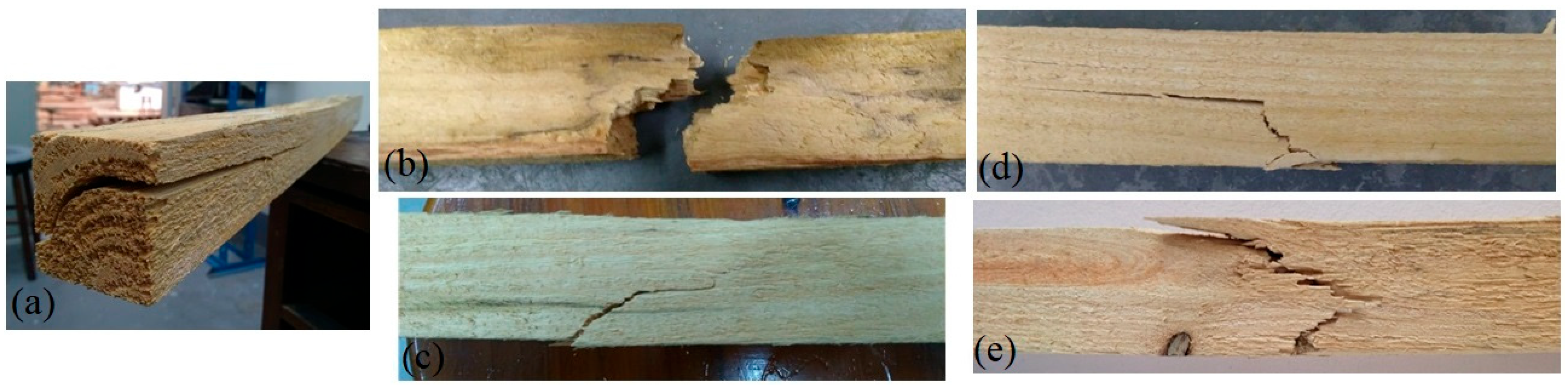
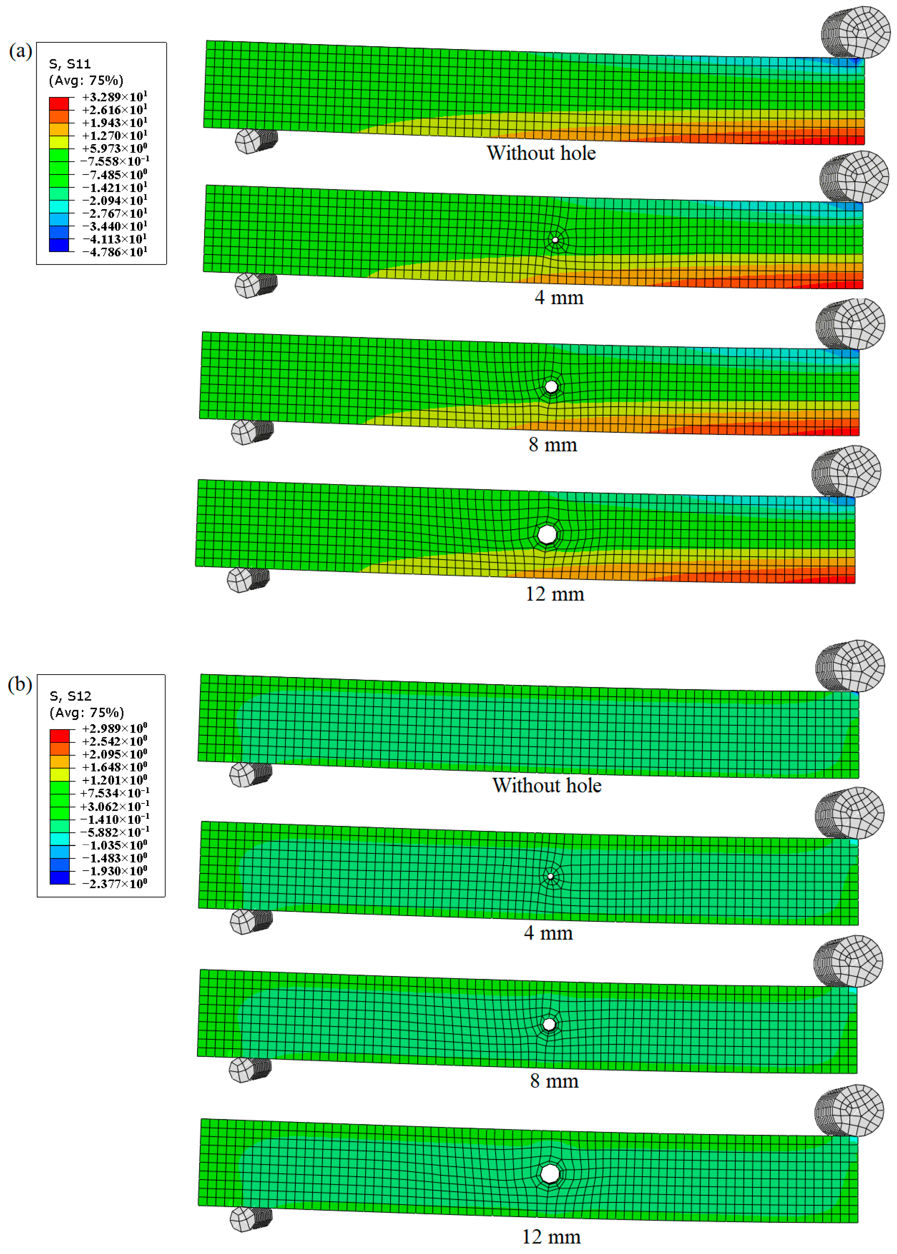
3.2. Quasi-Static Bending Analysis

To compute the bending modulus from experimental data, ASTM D143 [14] specifies a relationship between the moment produced by loading and the moment of inertia of the sample’s cross-section. This relationship is standard for the elastic region of most isotropic and homogeneous materials. However, this approach proves less reliable for modeling wood’s mechanical behavior. Timber, renowned for its unique anisotropic and heterogeneous nature, exhibits a nonlinear response under bending stress, particularly as it nears failure. The ASTM D143 approach presupposes elastic behavior within the proportional limit, potentially failing to capture accurately the intricate stress–strain relationship of timber. Brazilian standard ABNT NBR 7190 recommends a length/height (L/h) ratio of 21 for bending tests, surpassing the ratio proposed by ASTM D143 (L/h = 14.2). This adjustment aligns with our research objectives’ need for a more precise representation of wood’s mechanical behavior.
Zangiácomo et al. [24] argued that the sample geometry suggested by ASTM D143 leads to substantial displacements associated with shear stresses. These high displacements cause internal stress redistribution, compromising precise deflection measurements. Based on bending results from Pinus elliottii samples with an L/h ratio of 15, Zangiácomo et al. [24] proposed that this L/h ratio could be adjusted to 21 (as suggested by ABNT NBR 7190) by increasing the original force levels by 40%. In our study, curves adjusted according to this correction better matched the experimental results than uncorrected curves, validating Zangiácomo et al.’s theoretical explanation.
Figure 9 presents the median load vs. displacement curves derived from the experimental tests and numerical simulations. Once again, the experimental and numerical curves exhibited good agreement across all the cases, partly attributable to the aforementioned literature-based correction. The average bending modulus across the different groups showed no statistical differences. Typically, the small samples subjected to bending experience yielded on the compression side, followed by compression zone expansion, ultimately failing under tension in a brittle manner [25].
Various failure modes were observed during the bending tests, including horizontal shear (Figure 10a), brash tension (Figure 10b), cross-grain tension (Figure 10c), simple tension (Figure 10d), and splintering tension (Figure 10e). Visual analysis indicated no failures occurring in the hole region, suggesting that the drilled holes did not influence these failures. Thus, the influence of the holes can be discounted in this context.
In our study, we consistently observed results regarding failure modes and the effects of holes in wood that were aligned with the findings of Andarini and Raftery [26]. Their research identified similar failure modes, including horizontal shear, brash tension, cross-grain tension, simple tension, and splintering tension, indicative of wood’s complex behavior under bending stress, especially near holes. Our study corroborated these findings, highlighting the importance of considering these effects when designing and analyzing wood structures.
Figure 11 demonstrates that a hole’s presence, irrespective of its diameter, had no influence on the stresses developed longitudinally, with no effective stress concentration observed. The holes did not necessarily trigger failure in adjacent regions, aligning with Andarini and Raftery’s [26] findings. However, visual analysis of the failure modes indicated that most failures occurred in tension or compression regions, corroborating the numerical study, where these regions experienced high normal stresses. Conversely, Wen et al. [27] explored hole introduction in the compression and tension zones of solid wood beams, asserting that the holes shifted the neutral axis, primarily affecting the inelastic strain stage. Figure 11’s shear stress field confirms that the holes did not generate high stress, explaining why the experimental failures occurred in the longitudinal center of the samples.

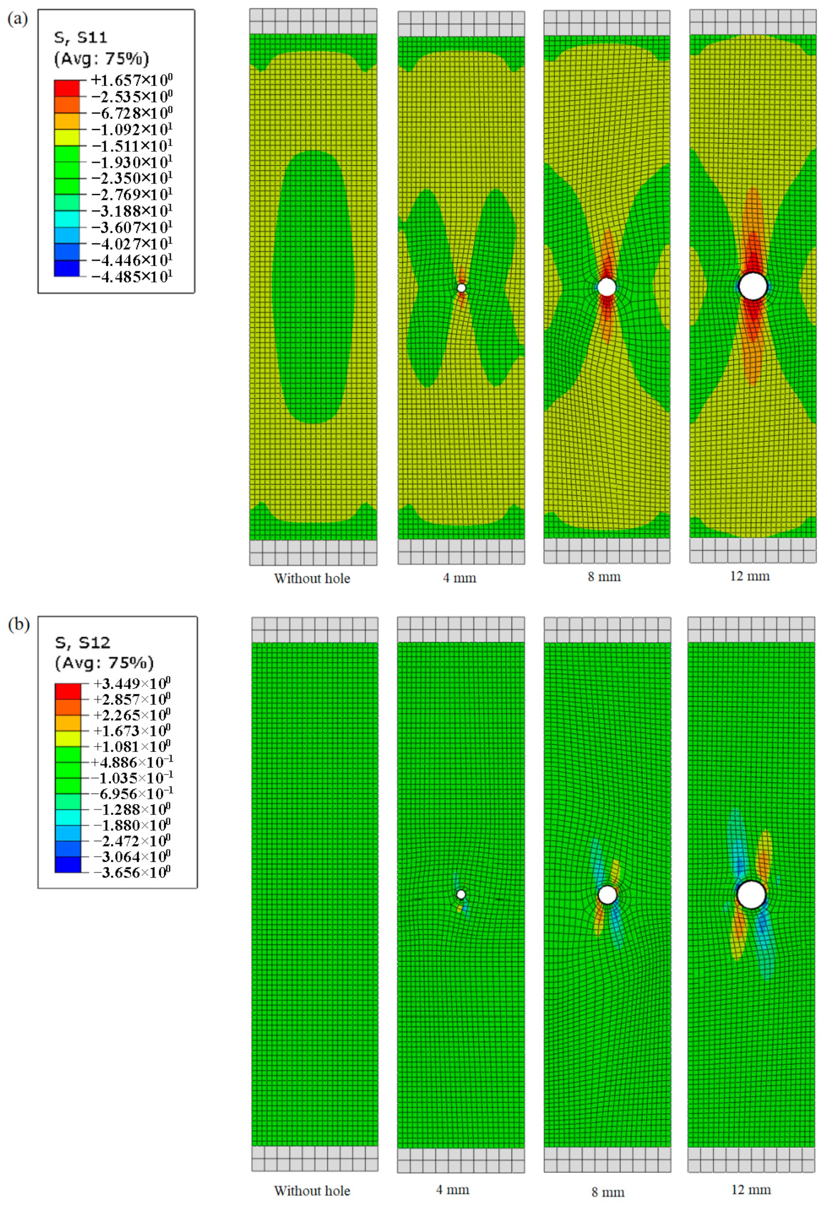
3.3. Tension Perpendicular to Grain

Figure 12 shows the experimental results from the tensile tests perpendicular to the grain. As with the other experimental tests, comparisons between the groups revealed no statistically significant differences in the stiffness or strength means. However, failures in this test occurred between the notches made to attach the supports, where the hole was positioned and followed the growth rings. Thus, this damage is likely to result from both the wood’s anatomical characteristics and the inserted holes.
The high standard deviations recorded in this experiment might stem from the short radial parenchyma cells found in pine wood. These cells, vital fluid conductors, vary in dimensions from 2 to 40 µm in length and 2 to 20 µm in width [28]. Additionally, the test’s loading configuration could induce a complex stress field, especially near the support zone, compromising the purity of normal stresses. This behavior was also evident in the FE model, as shown in Figure 12. It was observed that normal (Figure 13a) and shear (Figure 13b) stress around the device exceeded those around the holes, corroborating Sebek et al.’s [29] study. NBR 7190 [30] stipulates that tensile strength perpendicular to the grain should be used only for sample comparisons, not for wood structure applications. Thus, we did not compare the experimental tensile results with the numerical stiffness results, as an extensometer was not utilized in the tests to measure displacement, potentially yielding inaccurate comparisons.

4. Conclusions

The density and mechanical properties of the pine wood examined in this study were marginally lower than those reported in the literature. However, these values fall within the expected range considering the inherent variability of wood properties. The introduction of holes with varying diameters did not result in statistically significant reductions in the mechanical properties of the wood samples, as supported by both experimental and numerical findings. The pronounced stress concentration fields proximate to the holes, as revealed by the finite element (FE) model, elucidate the elevated occurrence of failure modes in these areas. Specifically, longitudinal cracks were predominant in compression parallel to the grain, while horizontal shear failures were prevalent in the bending tests. Moreover, the numerical models corroborated the elastic regions observed in the stress vs. deformation and load vs. displacement curves from the experimental compression parallel to the grain and bending tests, respectively. Adjustments to the experimental bending curves were successfully implemented based on the literature’s recommendations, rectifying the inappropriate length/height (L/h) ratio suggested by ASTM D143. In contrast, the tensile tests perpendicular to the grain exhibited elevated standard deviations. This variability can be attributed to both the anatomical characteristics of the pine wood under study and the inadequate test configuration prescribed by ASTM D143. In summary, this study underscores the importance of considering the effects of hole introduction and appropriate test configurations when assessing the mechanical behavior of wood. The findings provide valuable insights for future research and practical applications in wood engineering and design.

Author Contributions

Conceptualization, M.L.P.T. and R.A.D.; methodology, A.B.G. and A.P.A.; software, A.B.G. and M.L.P.T.; validation, R.A.D., D.A.G., A.L.M., R.B. and M.L.P.T.; formal analysis, A.B.G. and A.P.A.; investigation, A.B.G. and A.P.A.; resources, R.A.D.; data curation, A.B.G. and A.B.A.; writing—original draft preparation, A.B.G., R.A.D. and A.B.A.; writing—review and editing, D.A.G., A.L.M., R.B., M.L.P.T. and R.A.D.; visualization, A.B.A., D.A.G., A.L.M., R.B. and M.L.P.T.; supervision, R.A.D.; project administration, R.A.D.; funding acquisition, D.A.G., A.L.M., R.B. and R.A.D. All authors have read and agreed to the published version of the manuscript.

Funding

This work was supported by the Coordination for the Improvement of Higher Education—CAPES (code 001), the National Council for Scientific and Technological Development—CNPq.

Data Availability Statement

The raw data supporting the conclusions of this article will be made available by the authors on request.

Acknowledgments

The authors gratefully acknowledge the Coordination for the Improvement of Higher Education Personnel (CAPES), and the National Council for Scientific and Technological Development (CNPq) for their support.

Conflicts of Interest

The authors declare no conflicts of interest.

References

  1. Wimmers, G. Wood: A Construction Material for Tall Buildings. Nat. Rev. Mater. 2017, 2, 17051. [Google Scholar] [CrossRef]
  2. Qin, Y.; Dong, Y.; Li, J. Effect of Modification with Melamine–Urea–Formaldehyde Resin on the Properties of Eucalyptus and Poplar. J. Wood Chem. Technol. 2019, 39, 360–371. [Google Scholar] [CrossRef]
  3. Yoshihara, H.; Ataka, N.; Maruta, M. Analysis of the Open-Hole Compressive Strength of Spruce. Holzforschung 2016, 70, 449–455. [Google Scholar] [CrossRef]
  4. Yoshihara, H.; Maruta, M. Young’s Modulus and Shear Modulus of Open-Hole Spruce Measured by Vibration Tests. Wood Sci. Technol. 2019, 53, 1279–1294. [Google Scholar] [CrossRef]
  5. Reiner, J.; Pizarro, S.O.; Hadi, K.; Narain, D.; Zhang, P.; Jennings, M.; Subhani, M. Damage Resistance and Open-Hole Strength of Thin Veneer Laminates: Adopting Design and Testing Principles from Fibre-Reinforced Polymers. Eng. Fail. Anal. 2023, 143, 106880. [Google Scholar] [CrossRef]
  6. Mousavi, M.; Gandomi, A.H. Wood Hole-Damage Detection and Classification via Contact Ultrasonic Testing. Constr. Build. Mater. 2021, 307, 124999. [Google Scholar] [CrossRef]
  7. Chen, G.; Wu, J.; Jiang, H.; Zhou, T.; Li, X.; Yu, Y. Evaluation of OSB Webbed Laminated Bamboo Lumber Box-Shaped Joists with a Circular Web Hole. J. Build. Eng. 2020, 29, 101129. [Google Scholar] [CrossRef]
  8. Hallett, S.R.; Green, B.G.; Jiang, W.G.; Wisnom, M.R. An Experimental and Numerical Investigation into the Damage Mechanisms in Notched Composites. Compos. Part A Appl. Sci. Manuf. 2009, 40, 613–624. [Google Scholar] [CrossRef]
  9. Mascia, N.T. Análise de Tensões e Deslocamentos Em Peças Cilíndricas de Madeira Devido à Retração. Matéria 2015, 20, 32–46. [Google Scholar] [CrossRef]
  10. Mishnaevsky, L.; Qing, H. Micromechanical Modelling of Mechanical Behaviour and Strength of Wood: State-of-the-Art Review. Comput. Mater. Sci. 2008, 44, 363–370. [Google Scholar] [CrossRef]
  11. Sretenovic, A.; Müller, U.; Gindl, W.; Teischinger, A. New Shear Assay for the Simultaneous Determination of Shear Strength and Shear Modulus in Solid Wood: Finite Element Modeling and Experimental Results. Wood Fiber Sci. 2004, 36, 302–310. [Google Scholar]
  12. Yang, N.; Li, T.; Zhang, L. A Two-Dimensional Lattice Model for Simulating the Failure and Fracture Behavior of Wood. Wood Sci. Technol. 2020, 54, 63–87. [Google Scholar] [CrossRef]
  13. Aira, J.R.; Descamps, T.; Van Parys, L.; Léoskool, L. Study of Stress Distribution and Stress Concentration Factor in Notched Wood Pieces with Cohesive Surfaces. Eur. J. Wood Wood Prod. 2015, 73, 325–334. [Google Scholar] [CrossRef]
  14. ASTM D143-21; Standard Test Methods for Small Clear Specimens of Timber. ASTM International: West Conshohocken, PA, USA, 2023; p. 31. [CrossRef]
  15. Acosta, A.P.; de Avila Delucis, R.; Amico, S.C.; Gatto, D.A. Fast-Growing Pine Wood Modified by a Two-Step Treatment Based on Heating and in Situ Polymerization of Polystyrene. Constr. Build. Mater. 2021, 302, 124422. [Google Scholar] [CrossRef]
  16. Hein, P.R.G.; Chaix, G.; Clair, B.; Brancheriau, L.; Gril, J. Spatial Variation of Wood Density, Stiffness and Microfibril Angle along Eucalyptus Trunks Grown under Contrasting Growth Conditions. Trees Struct. Funct. 2016, 30, 871–882. [Google Scholar] [CrossRef]
  17. Moraisa, M.C.; Pereira, H. Heartwood and Sapwood Variation in Eucalyptus Globulus Labill. Trees at the End of Rotation for Pulpwood Production. Ann. For. Sci. 2007, 64, 665–671. [Google Scholar] [CrossRef]
  18. Svensson, S.; Toratti, T. Mechanical Response of Wood Perpendicular to Grain When Subjected to Changes of Humidity. Wood Sci. Technol. 2002, 36, 145–156. [Google Scholar] [CrossRef]
  19. Forest Products Laboratory. Wood Handbook: Wood as an Engineering Material; Forest Products Laboratory: Madison, WI, USA, 2010. [Google Scholar]
  20. Barbero, E.J. Introduction to Composite Materials Design; CRC Press: Boca Raton, FL, USA, 2010; ISBN 9780429109478. [Google Scholar]
  21. Acosta, A.P.; Beltrame, R.; Missio, A.L.; de Avila Delucis, R.; Gatto, D.A. Juvenile and Mature Woods from Pine Subjected to in Situ Polymerization with Furfuryl Alcohol. Wood Mater. Sci. Eng. 2020, 17, 151–156. [Google Scholar] [CrossRef]
  22. Mohebby, B.; Kevily, H.; Kazemi-Najafi, S. Oleothermal Modification of Fir Wood with a Combination of Soybean Oil and Maleic Anhydride and Its Effects on Physico-Mechanical Properties of Treated Wood. Wood Sci. Technol. 2014, 48, 797–809. [Google Scholar] [CrossRef]
  23. Tang, J.; Song, X.; Lu, Y. An Elastic-Plastic Kinking Layer Model for Parallel-to-Grain Wood Embedment Behavior Considering Wood Drilling Damage. Eng. Struct. 2023, 280, 115656. [Google Scholar] [CrossRef]
  24. Zangiácomo, A.L.; Christoforo, A.L.; Lahr, F.A.R. Módulo de Elasticidade Aparente Em Vigas Roliças Estruturais de Madeira Pinus Elliottii. Ambient. Construído 2014, 14, 7–13. [Google Scholar] [CrossRef]
  25. Crespo, J.; Majano-Majano, A.; Lara-Bocanegra, A.J.; Guaita, M. Mechanical Properties of Small Clear Specimens of Eucalyptus Globulus Labill. Materials 2020, 13, 906. [Google Scholar] [CrossRef] [PubMed]
  26. Andarini, R.D.; Raftery, G.M. Experimental Assessment of Self-Tapping Screws for the Reinforcement of Multiple Holes in Laminated Veneer Lumber Beams. Structures 2023, 57, 105275. [Google Scholar] [CrossRef]
  27. Wen, Y.; Yang, P.; Zhao, J.; Zhao, D. Theoretical and Experimental Considerations on the Neutral Axis of Wood Beams with a Hole in Different Locations. Holzforschung 2018, 72, 769–777. [Google Scholar] [CrossRef]
  28. Emaminasab, M.; Tarmian, A.; Pourtahmasi, K. Permeability of Poplar Normal Wood and Tension Wood Bioincised by Physisporinus Vitreus and Xylaria Longipes. Int. Biodeterior. Biodegrad. 2015, 105, 178–184. [Google Scholar] [CrossRef]
  29. Šebek, F.; Kubík, P.; Tippner, J.; Brabec, M. Orthotropic Elastic–Plastic–Damage Model of Beech Wood Based on Split Hopkinson Pressure and Tensile Bar Experiments. Int. J. Impact Eng. 2021, 157, 103975. [Google Scholar] [CrossRef]
  30. ABNT. Projeto de Estruturas de Madeira; Associação Brasileira de Normas Técnicas (ABNT): Rio de Janeiro, Brazil, 2022; Volume 81. [Google Scholar]
Figure 1. Sample for compression test parallel to the fibers.
Forests 15 00722 g001
Figure 2. Sample for the bending tests and its shear diagram.
Forests 15 00722 g002
Figure 3. Sample for tension perpendicular to the grain tests.
Forests 15 00722 g003
Figure 4. FE model with local coordinate system of the wood to represent the (a) compressive (frontal and upper views), (b) bending (frontal and side views), and (c) tensile (frontal and side views) condition.
Forests 15 00722 g004
Figure 5. Convergence plot of the bending element.
Forests 15 00722 g005
Figure 6. Compressive stress vs. strain curves (a), modulus of elasticity (b), and modulus of rupture (c) of the wood samples with and without holes.
Forests 15 00722 g006
Figure 7. Photographic representations of longitudinal cracks observed during compression parallel to grain tests for 8 mm (a) and 12 mm (b) samples.
Forests 15 00722 g007
Figure 8. Diagrams for normal (a) and shear (b) stress field distributions developed in the compression parallel to grain tests for the wood samples with and without holes.
Forests 15 00722 g008
Figure 9. Load vs. displacement curves (a), modulus of elasticity (b), and modulus of rupture (c) for bending tests on wood samples with and without holes.
Forests 15 00722 g009
Figure 10. Horizontal shear (a), brash tension (b), cross-grain tension (c), simple tension (d), and splintering tension (e) failures observed during bending tests.
Forests 15 00722 g010
Figure 11. Diagrams illustrating normal (a) and shear (b) stress field distributions developed during bending tests on wood samples with and without holes.
Forests 15 00722 g011
Figure 12. Force vs. displacement curves (a), modulus of elasticity (b), and maximum stress (c) for tensile tests perpendicular to grain on wood samples with and without holes.
Forests 15 00722 g012
Figure 13. Diagrams illustrating normal (a) and shear (b) stress field distributions developed during tensile tests on wood samples with and without holes.
Forests 15 00722 g013
Table 1. Mechanical properties of the pine wood used in the present study.
E 1   * E 2 E 3 v 12 v 21 v 13 v 31 v 23 v 32 G 12 G 13 G 23
68483085070.4440.0200.3920.0290.3870.63636337768
MPaMPaMPa------MPaMPaMPa
* 1, 2, and 3 directions refer to longitudinal, transverse, and radial directions of the fibers, respectively; E is elastic modulus; v is Poisson’s ratio; G is shear modulus.
Table 2. Parameters of the stiffness matrix used to represent the orthotropy nature of wood (values represented in MPa).
D 1111 D 2222 D 3333 D 1122 D 1133 D 2233 D 1212 D 1313 D 2323
7041.35415.62685.19291.53389.79272.96363.00377.0068.00
Disclaimer/Publisher’s Note: The statements, opinions and data contained in all publications are solely those of the individual author(s) and contributor(s) and not of MDPI and/or the editor(s). MDPI and/or the editor(s) disclaim responsibility for any injury to people or property resulting from any ideas, methods, instructions or products referred to in the content.

