Article

Hydrogen Generation from Catalytic Steam Reforming of Acetic Acid by Ni/Attapulgite Catalysts

1
School of Earth Science and Environmental Engineering, Anhui University of Science and Technology, Huainan 232001, China
2
School of Chemical Engineering, Anhui University of Science and Technology, Huainan 232001, China
*
Author to whom correspondence should be addressed.
Catalysts 2016, 6(11), 172; https://doi.org/10.3390/catal6110172
Submission received: 26 September 2016 / Revised: 24 October 2016 / Accepted: 31 October 2016 / Published: 4 November 2016
(This article belongs to the Special Issue Reforming Catalysts)

Abstract

:
In this research, catalytic steam reforming of acetic acid derived from the aqueous portion of bio-oil for hydrogen production was investigated using different Ni/ATC (Attapulgite Clay) catalysts prepared by precipitation, impregnation and mechanical blending methods. The fresh and reduced catalysts were characterized by XRD, N2 adsorption–desorption, TEM and temperature program reduction (H2-TPR). The comprehensive results demonstrated that the interaction between active metallic Ni and ATC carrier was significantly improved in Ni/ATC catalyst prepared by precipitation method, from which the mean of Ni particle size was the smallest (~13 nm), resulting in the highest metal dispersion (7.5%). The catalytic performance of the catalysts was evaluated by the process of steam reforming of acetic acid in a fixed-bed reactor under atmospheric pressure at two different temperatures: 550 °C and 650 °C. The test results showed the Ni/ATC prepared by way of precipitation method (PM-Ni/ATC) achieved the highest H2 yield of ~82% and a little lower acetic acid conversion efficiency of ~85% than that of Ni/ATC prepared by way of impregnation method (IM-Ni/ATC) (~95%). In addition, the deactivation catalysts after reaction for 4 h were analyzed by XRD, TGA-DTG and TEM, which demonstrated the catalyst deactivation was not caused by the amount of carbon deposition, but owed to the significant agglomeration and sintering of Ni particles in the carrier.

1. Introduction

In the past decades, environmental pollution and energy consumption have increased rapidly all over the world, particularly in populous nations such as China and India. In order to relieve these situations, clean and renewable energies with high energy density and environment-friendly nature have attracted significant attention at present [1,2,3]. Hydrogen energy has long been known as a clean energy and an important alternative for fossil fuel. However, the conventional hydrogen production method is steam reforming (SR) of non-renewable fossil fuels, such as coal, nature gas and naphtha. These processes produce a large amount of CO2 causing the global warming phenomenon, accompanied by the depletion of fossil fuel reserves. Thus, it is profitable to study the exploitation of hydrogen generation technology from renewable energy sources, i.e., biomass that is carbon neutral [4]. One of the most promising ways for employing biomass to produce hydrogen is SR of bio-oil obtained by fast-pyrolysis of biomass resources [5,6,7]. Garcia L. [8] and Galdamez J.R. [9] conducted the SR of bio-oil in fixed-bed micro-reactor and fluidized-bed reactor under different conditions respectively, and they all demonstrated that the process of SR of bio-oil was a promising way to produce hydrogen. Bio-oil is a mixture of different kinds of organic compounds, such as carboxylic acids, polyhydric alcohols, ketones, sugars, aldehydes, phenols and more complex compounds [10,11]. They can be separated into two fractions by adding water. One is non-aqueous and contains lignin derivatives that have a high economic value [12]. The other is aqueous and contains many oxygenated compounds, such as acids, aldehydes, ketones and alcohols, which do not have many applications but can be reformed to produce hydrogen production [13]. Therefore, SR of the components derived from bio-oil is more convenient and it can provide much information for both optimizing experiment conditions and designing highly active and stable catalysts for SR of real bio-oil. Acetic acid (AA) has often been investigated as a model compound for hydrogen production by way of SR because AA is one of the major components (12–30 wt %) in bio-oil [4]. However, the efficiency of hydrogen production via steam reforming of acetic acid (SRAA) is very low because AA is a safer hydrogen carrier with non-inflammable nature [14]. Based on these special characteristics, hydrogen production from SRAA using various catalysts has been widely studied by different research groups [14,15,16,17,18,19,20,21,22,23,24,25,26,27,28,29,30,31].
The catalysts in their research were mainly concentrated on the transition metal catalysts (e.g., Ni, Fe, Co and Cu [14,15,16,17,18,19,20,21,22,23,24,25]) and noble metal catalysts (e.g., Pd, Pt, Rh, and Ru [26,27,28,29,30,31]). The results revealed that Ni and Ru catalysts had higher activity and selectivity for hydrogen production through the process of SRAA. Compared with Rh-based catalysts, the Ni-based catalysts attracted more attention due to its economical efficiency and high activity for C–C and C–H bonds cleavage. Bimbela F. et al. [32] prepared three Ni/Al2O3 catalysts with different Ni content (23%, 28% and 33%) by using coprecipitated technology and they were applied into the process of SRAA at 650 °C. The results showed that the 28%-Ni/Al2O3 performed better than the other two. Medrano J.A. et al. [33] carried out the SR of AA and hydroxyacetone (acetol) in fluidized bed reactor over Ni/Al catalysts modified with Ca or Mg at 650 °C, and the results revealed the catalyst with a Mg/Al ratio of 0.26 had the highest carbon conversion and H2 yield. Hu X. et al. [14] investigated acetic acid steam reforming for hydrogen production using transition metal catalysts (Ni, Fe, Co or Cu)/Al2O3 prepared by incipient wetness impregnation at 573–873 K. The results from his team showed that Ni and Co had higher activity for C–C and C–H bonds cleavage, while the Ni/Al2O3 catalyst was more stable than Co/Al2O3 catalyst. However, the utilization of nickel-based catalysts is frequently associated with some problems during the process of SRAA, such as catalyst beds occlusion and deactivation of catalysts because of the sintering of active metal and poor coke resistance [17,34]. Therefore, some bimetallic catalysts (such as Fe-Co, Ni-Co and Ni-Pd [16,20,35]) and various carriers with unique properties (e.g., Al2O3, CeO2, ZrO2, MgO, TiO2 and attapulgite [19,20,21,23,30,36,37]) have been widely studies. Assaf P.G.M et al. [16] conducted a research of Ni-Co/Al2O3 bimetallic catalyst prepared by wet impregnation, and this catalyst showed the highest selectivity for H2 and CO2 in the SRAA at 500 °C. Dancini-Pontes I. et al. [38] demonstrated that bimetallic Cu-Ni/Na2O-Nb2O5 catalyst also had a good selectivity for H2 and CO2, however TEM images found some active metal was sintered due to low metal-support interaction. In the work of Nichele V. et al. [39] the performance of Ni/ZrO2 modified with Ca in ethanol SR was studied. They demonstrated CaO increased the Ni reducibility and decreased the Lewis acidity of ZrO2, resulted in inhibiting coke deposition and improving the carbon balance.
The variations in structure of catalysts, caused by different preparation methods, can improve the selectivity and stability of catalysts during SRAA, because the active metal species and carriers have influence on reaction pathways [40]. Luo X. et al. [41] researched different preparation methods for preparing nano-NixMgyO catalysts that were used in SR of methanol. The results showed that the NixMgyO-hydro catalyst prepared by hydrothermal method achieved the highest conversion of methanol (97.4%) and yield of H2 (58.5%), and had outstanding coke deposition resistance. The results demonstrated this situation was attributed to the metal support interaction (MSI) of the NixMgyO solid solution structure, which prevented Ni nanoparticles from aggregation. Silva et al. [42] evaluated hydrogen production from SR of ethanol used Ni-Cu/NbxOy catalysts obtained by co-precipitation (CP), wet impregnation (WI) and ion exchange (IE). The results of characterizations demonstrated that differences in crystal structure and MSI caused by different preparations have altered the reducibility of the catalysts.
In previous study [37], we investigated hydrogen production for SR of bio-oil employing Ni, Fe and Ni-Fe supported on attapulgite clay (ATC), also called palygorskite, which has an outstanding adsorption capacity for reactant and thermostability. In this study, all catalysts were prepared by coprecipitation method. The results showed that ATC could disperse active metal species and change the production distributions.
Because the active metal surface and support structure could be altered by preparation method, the aims of this paper were to modify the textural properties of Ni/ATC catalysts by precipitation, impregnation and mechanical blending, and evaluate them on the conversion efficiency of AA, the yield of H2, the selectivity of carbonaceous gas (such as CH4, CO and CO2). In addition, we also investigated the stability of all catalysts by SRAA at 550 °C and 650 °C.

2. Results and Discussion

2.1. Catalyst Characterizations
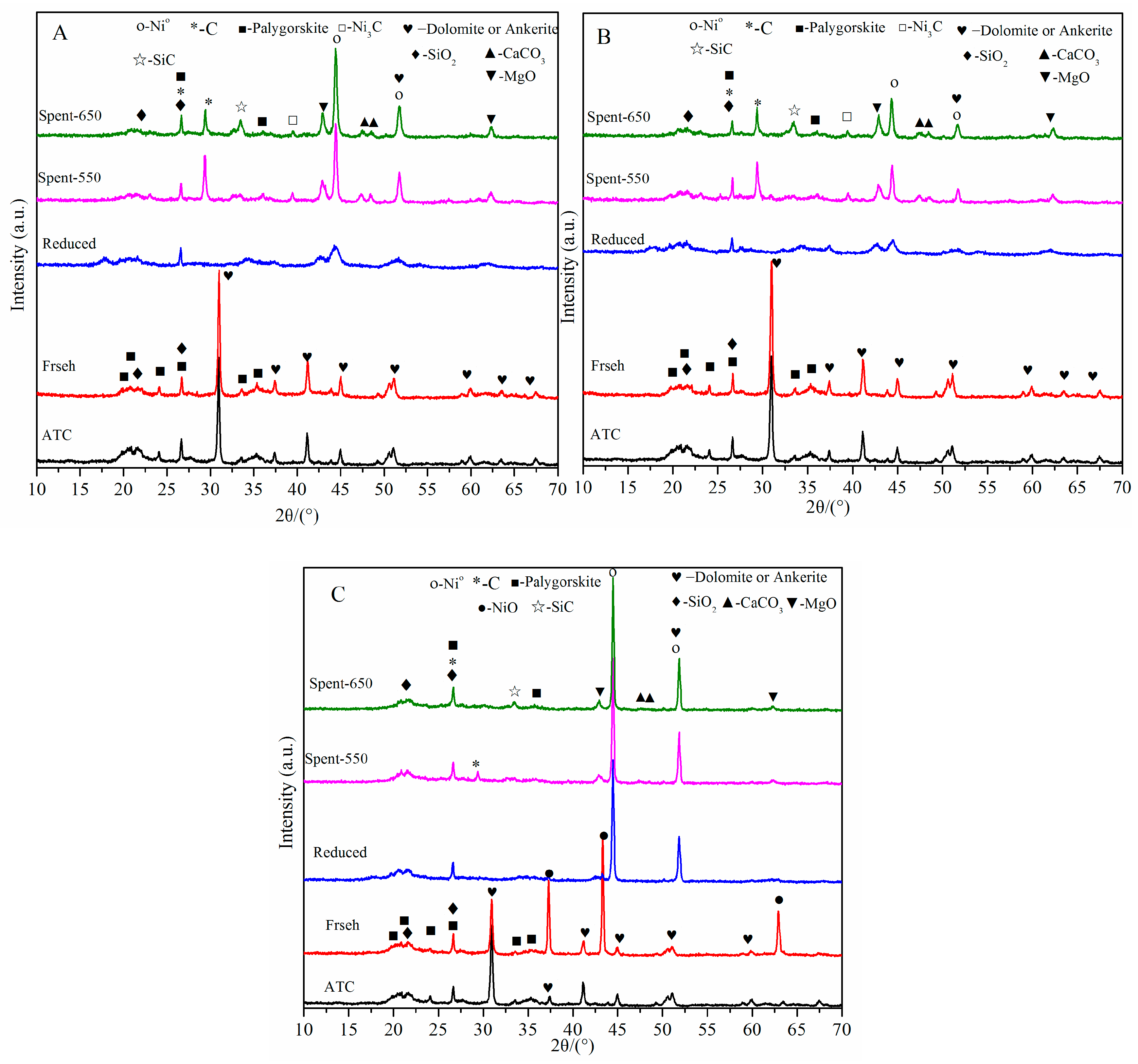
2.1.1. XRD Analysis

X-ray diffraction patterns of fresh, reduced and spent catalysts are shown in Figure 1. It can be found that the peaks at 2θ of 19.8°, 20.8° 24.2°, 26.7°, 33.6° and 35.3° in ATC and all fresh catalysts exhibit good consistence with palygorskite (JCPDS PDF# 31-0783), and the peaks at 30.8°, 37.3°, 41.2°, 45.0°, 51.2°, 59.9°, 63.5° and 67.4° may belong to dolomite (JCPDS PDF# 99-0046) or ankerite (JCPDS PDF# 99-0011). The peaks at 21.0° and 26.6° are an amorphous reactive SiO2, and it has some advantages in synthesizing highly active loaded catalysts because of its high adsorption capacity [11,43]. In addition, the diffraction peaks of palygorskite and SiO2 are not changed after reduction and reaction, which shows that the base structure of ATC does not change in these processes. It is worth noting that the peaks attributed to crystal structure of dolomite or ankerite disappear after reduction and reaction, which shows that dolomite or ankerite is reduced to some amorphous species and the ATC structure has been partly destroyed.
Figure 1 also shows that the characteristic diffraction peaks of nickel oxide phase at 37.2°, 43.3° and 62.9° (JCPDS PDF# 44-1159) in fresh catalysts only appear in MM-Ni/ATC catalyst. Furthermore, the diffraction peaks at 2θ of 44.5° and 51.8° are attributed to crystal phase of Ni° species (JCPDS PDF# 04-0850) in all reduced and spent catalysts. This is because NiO species are highly disperse on the surface of ATC and strongly interactive with ATC through the synthesis methods of precipitation and impregnation, resulting in the crystal phase of NiO which cannot be detected by XRD in fresh PM-Ni/ATC and IM-Ni/ATC catalysts [25,41]. By comparison, among the XRD spectra of reduced and spent catalysts of these three Ni/ATC catalysts, the intensities of the Ni° peaks are increased in the order of MM-Ni/ATC > PM-Ni/ATC > IM-Ni/ATC. In addition, the Ni° phase diffraction peaks in reduced PM-Ni/ATC and IM-Ni/ATC catalysts are broader than those of reduced MM-Ni/ATC catalyst. This situation is mainly because the interaction between active metal Ni and ATC in Ni/ATC catalyst prepared by mechanical blending method is weaker than those of the other two catalysts. This result manifests that the bonding crystal force inside the structures of PM-Ni/ATC and IM-Ni/ATC is stronger than that of MM-Ni/ATC. It is well known that Ni° particles in Ni-based catalysts contribute to the catalytic activation of SR reaction [17,41]. Because of the weak bonding force in MM-Ni/ATC, these free Ni particles are easily reduced deeply before reaction, which results in the higher activation at the initial stage of the reaction. Meanwhile, these free Ni particles could also overcome the crystal force of surface and agglomerate to emerge larger size crystallites during the reforming process, which accelerates the deactivation of the catalysts [41]. These results are demonstrated by catalytic test of all catalysts, as shown in Section 2.2.
The metallic dispersion (Dm) is calculated according to the XRD measurements by using the equation: Dm = 101/dNi [44,45,46], where dNi (nm) is the crystallite size of Ni particles calculated by the Scheerer equation, and the constant 101 is calculated through assuming that Ni particles have a uniform spherical geometry and the density of Ni particles on a polycrystalline surface is 1.54 × 10¹⁹ atoms of Ni per m2. The crystallite sizes and the metallic dispersions in the catalysts after reduction are presented in Table 1. There is a highest nickel dispersion value (7.5%) in the PM-Ni/ATC catalyst among the three catalysts. It is attributed to precipitation method synthesis, which could promote the Ni particles dispersion on the surface of ATC and decrease the crystallite size of Ni. This is the reason why the PM-Ni/ATC has significantly higher activity and stability during the reforming reaction, as shown in Section 2.2.

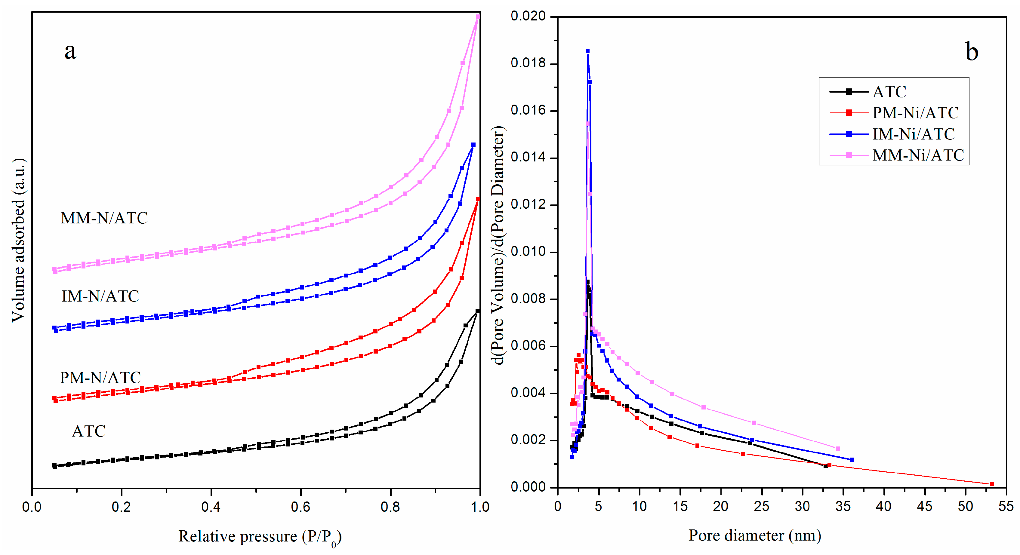
2.1.2. N2 Adsorption–Desorption Analysis

The N2 adsorption–desorption isotherms and pore size distributions of ATC and fresh catalysts are presented in Figure 2, and their textural properties are shown in Table 1. The isotherms of all the catalysts are similar to that of ATC, and belong to classical type III (typical for clays) according to IUPAC classification [47]. The isotherm of pure ATC shows a limited N2 uptake at p/po < 0.50 combined with a large N2 uptake at p/po > 0.85. This result corresponds to the surface area of 40.6 m2/g and the pore volume of 0.10 cm3/g as listed in Table 1. From Table 1, it also displays that the surface areas of the three catalysts, which are similar to one another, are significantly increased compared with that of ATC, and the pore volumes of them are very close to that of ATC. In short, the three synthesis methods can enlarge the surface areas of the catalysts, and further enhance the catalytic activity and metallic dispersion of them [41,48]. Both nature ATC and the three Ni/ATC catalysts exhibit well-defined hysteresis loops of H3 Type (Figure 2a), demonstrating that the samples are made up of plate-like particles (loose assemblages) forming slit-like pores [47]. The pore size distributions and the pore diameters of all samples are presented in Figure 2b and Table 2, respectively. The results exhibit a pronounced mesoporous characteristic of these samples and the pore size distributions are in the range of 2~10 nm. In short, the addition of Ni into ATC slightly decreases the pore diameter mainly because of the partial pore-blocking by nickel particles.

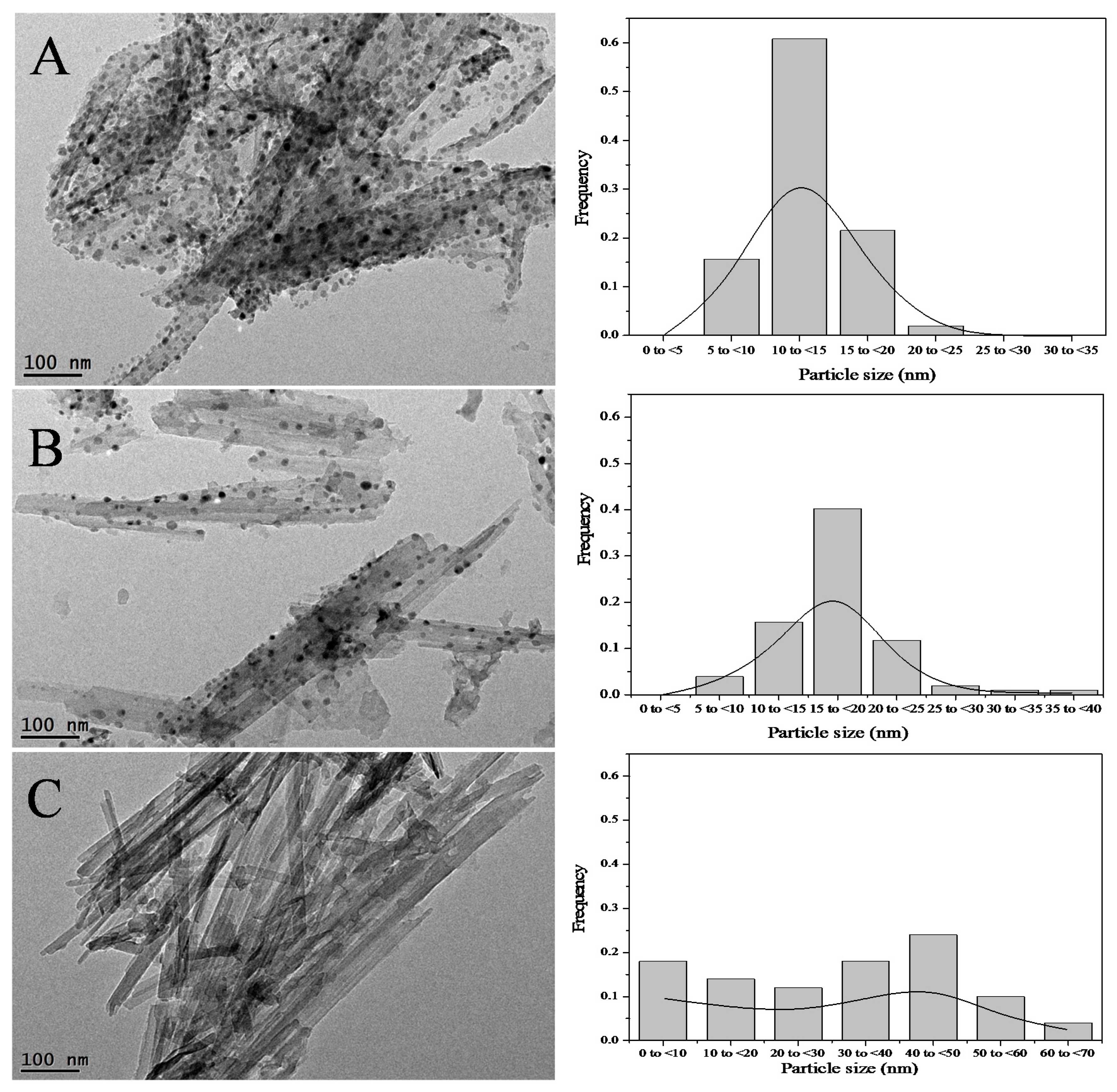
2.1.3. TEM Analysis of Reduced Catalysts

In order to study the variation on structures of the three catalysts caused by different synthesis methods, TEM analysis was further employed in this research. The TEM images of three reduced catalysts are shown in Figure 3. The morphologies of three reduced catalysts have similar matrix structure, which is individual fiber or fiber-shaped cluster. The result of the research is consistent with the structure of pristine ATC in the literature [49,50]. In Figure 3A,B, it can be seen that the analogy in respect of morphology between PM-Ni/ATC and IM-Ni/ATC were also observed, which may be ascribed to their similar preparation procedure [41]. As shown in Figure 3C, the Ni particle size on the surface of MM-Ni/ATC is larger and the aggregation of them is severer than those of the other two catalysts. This result agrees with the lower bonding force between Ni and ATC support, which is demonstrated by XRD. Figure 3 shows that the Ni particle size distribution of PM-Ni/ATC relatively focuses on the range of 10~15 nm and the mean value is 13.0 nm, which is consistent with the value as listed in Table 1. Thus, it has the highest activity and H2 yield in the overall process of SRAA reaction, as shown in Section 2.2.

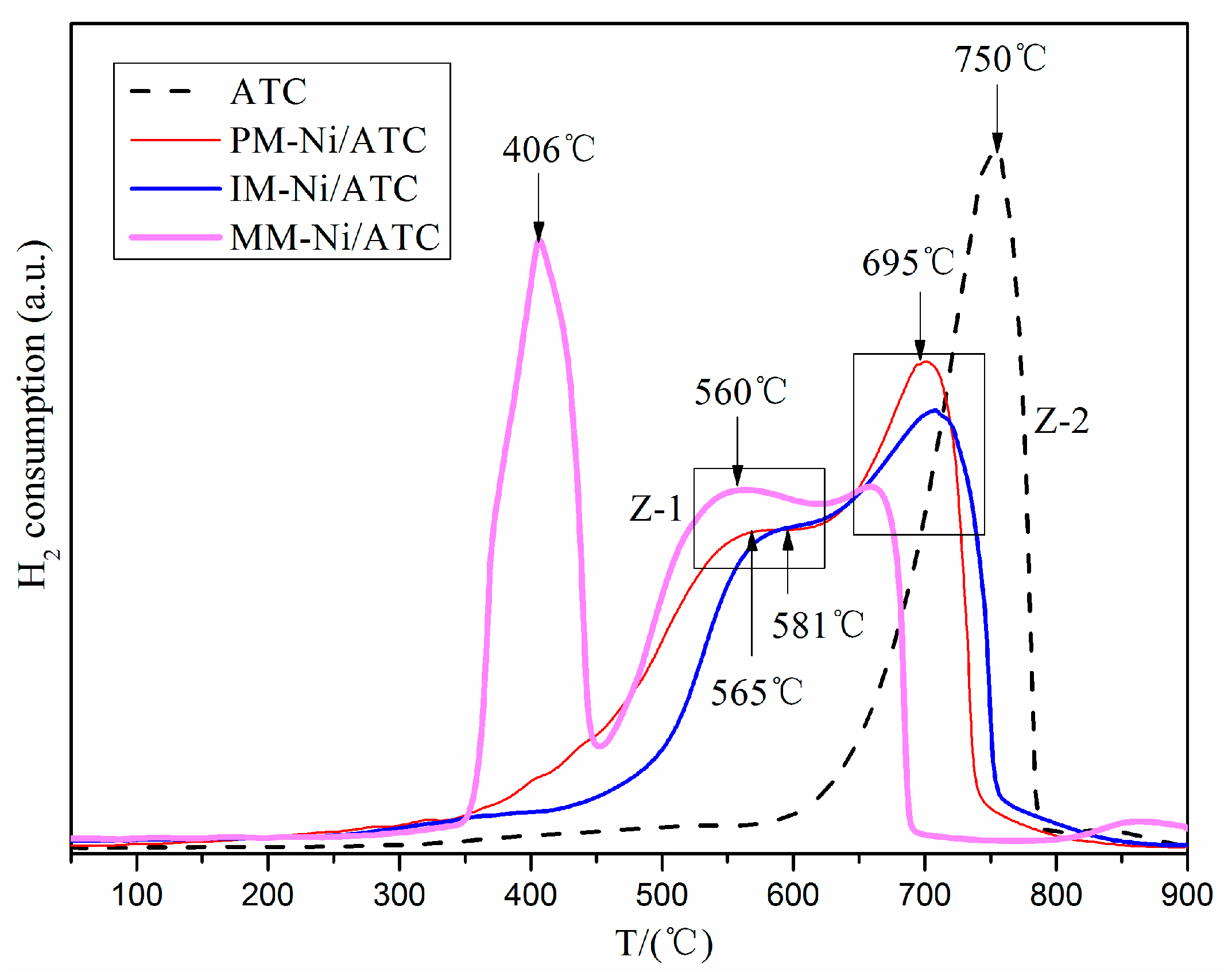
2.1.4. H2-TPR Test of Fresh Catalysts

H2-TPR test is conducted over the fresh catalysts to study the reducibility of nickel oxides with different synthesis methods and the result profiles are shown in Figure 4. According to the previous literature [51,52], the reduction behavior of pure NiO typically showed a single H2 consumption peak at around 673 K. The reduction of nickel species with strong interaction with the oxide support was significantly hindered, producing higher reduction temperatures than pure NiO [16,17,34,46]. For natural ATC, there is an obvious reduction peak starting at 500 °C and centered around 750 °C, as displayed in Figure 4. The result shows that the nature ATC can be highly reduced at high temperature (>700 °C) and its structure will be partly destroyed. This was demonstrated by XRD (Figure 1), in which the diffraction peaks at 2θ of 30.8°, 37.3°, 41.2°, 45.0°, 51.2°, 59.9°, 63.5° and 67.4° disappear after reduction. It can also be seen from Figure 4 that there is an apparent reduction peak located at low temperature (406 °C) in MM-Ni/ATC sample, which is attributed to “free” NiO or nickel oxide species with no interaction with the ATC. This is consistent with the X-ray diffraction spectrogram of fresh MM-Ni/ATC sample (Figure 1c), in which the diffraction peaks of NiO are apparent. Therefore, there are many Ni2+ species are reduced to Ni° in this catalyst at relatively low temperature. This is also the reason why the MM-Ni/ATC catalyst has a higher activity at the initial stage of reaction (0~30 min), as shown in Section 2.2.
In addition, it is observed that there are two zoned peaks located in the range of 550~700 °C in the three fresh catalysts (Figure 4), which are attributed to the reduction of nickel oxide species interaction at different degrees with the ATC. One (Z-1) located at around 550~600 °C is attributed to the reduction of NiO on the surface of the ATC with little or weak interaction with the support, the other (Z-2) located at 650~700 °C belongs to the reduction of NiO in the pores and interlayer of the ATC in intimate contact with the support. This agrees with the results of the literature [53]. Furthermore, the center reduction temperatures of the three catalysts in the two zones exhibit similar tendency, which are as below: MM-Ni/ATC < PM-Ni/ATC ≈ IM-Ni/ATC (Figure 4). This result is further demonstrated that the bonding force between nickel species and ATC is weak in MM-Ni/ATC sample.

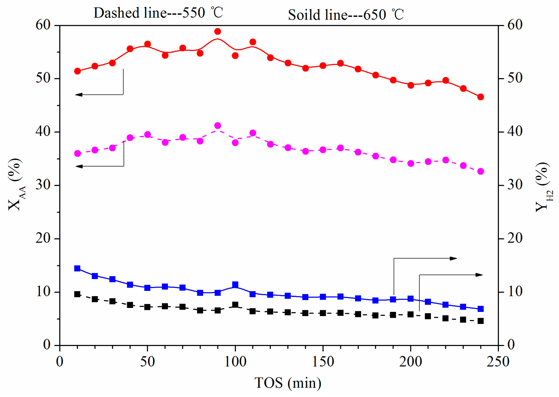
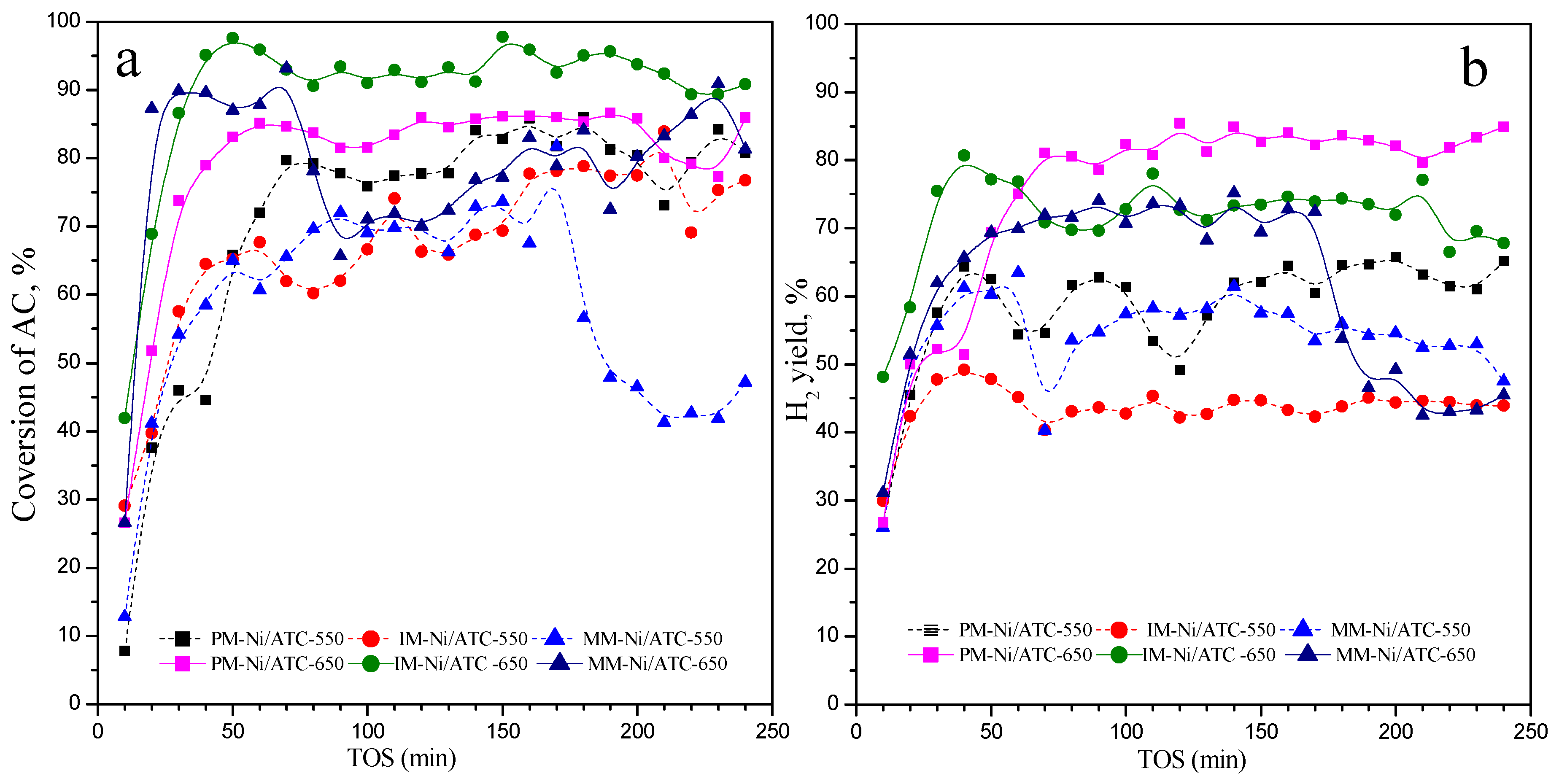
2.2. Catalytic Performance

SRAA for hydrogen production was carried out by using the three kinds of catalysts in a continuous-flow fix-bed tubular reactor, and reaction conditions were 3.00 g catalyst with N2 flow rate of 0.24 L/min, feed flow rate of 14 mL/h and H2O/AA molar rate of 6 at 550 °C and/or 650 °C. In addition, to exclude the reactor walls effect and further understand the catalytic performance, an experiment only with the 3.00 g ATC was conducted under the same conditions. The results are displayed in Figure 5, in which the conversion of AA (XAA) and the yield of H2 ( Y H 2 ) are very low over the ATC. The XAA and Y H 2 have a slight increase when the temperature increased from 550 °C to 650 °C. Figure 6 shows the XAA and Y H 2 changes with time on steam (TOS) at different temperature. It can be seen in Figure 6 that the XAA and Y H 2 are increased with increasing temperature, but they are significantly higher than those in Figure 5. The means of XAA over PM-Ni/ATC, IM-Ni/ATC and MM-Ni/ATC are 75.0%, 86.5% and 76.5% (as listed in Table 2) at 650 °C during 2 h, respectively, and are higher than those at 550 °C during 2 h; meanwhile, the means of H2 yields have a similar tendency with the AA conversions, as shown in Table 2. Furthermore, Table 2 clearly shows that the selectivity of CO decreases with increasing temperature, but the selectivity of CH4 has a reversed tendency. It is worth noting that the activities of the three catalysts are different at 650 °C (Figure 5a,b). For IM-Ni/ATC catalyst, its conversion of AA is the highest of the three catalysts, but the H2 yield is lower than that of PM-Ni/ATC. Figure 6a,b also shows that the XAA and Y H 2 over the MM-Ni/ATC catalyst at 650 °C are higher than that over the PM-Ni/ATC catalyst and lower than that over the IM-Ni/ATC catalyst in the initial stage of reaction (0~50 min). However, those over the MM-Ni/ATC catalyst are the lowest among the three catalysts at long-term reaction and its H2 yield rapidly decreases after 120 min of reaction. In addition, the PM-Ni/ATC catalyst shows the highest Y H 2 (~82%) and outstanding stability during 4 h of reaction at 650 °C.
CH3COOH → CO, H2, CO2, CH4 + coke
CH3COOH + 2H2O → 4H2 + 2CO2
CH4 + H2O ⇔ 3H2 + CO
CO2 + 4H2 ⇔ CH4 + 2H2O
For these results, there are several reasons to account for them. First of all, the process of SRAA contained many complex reactions, such as AA thermal decomposition (r1), and SR (r2 and r3) [22,25], which were all endothermic reactions, therefore high temperature was beneficial to these reactions. However, methanation (reverse reaction of r3 and r4) was exothermic reaction, so high temperature had an adverse effect for CH4 formation [46]. Therefore, the increase of the selectivities of CH4 at 650 °C over three catalysts compared with those at 550 °C (Table 2) was mainly because of the AA thermal decomposition (r1). Secondly, the mesostructure in the three Ni/ATC catalysts, which has been evaluated by N2 adsorption–desorption (Figure 2), provides the reactant accessible nickel active sites. Meanwhile, the Ni particle size (13.5 nm) on PM-Ni/ATC is the smallest among the three catalysts (Table 1). It is well known that small nickel particles exhibit strengthened capabilities for enhancing the reaction of SR and suppressing the carbon deposition [16,53,54]. Finally, the stronger interaction between Ni particles and the ATC in Ni/ATC catalysts prepared by precipitation and impregnation methods, which has been proven by XRD in Section 2.1.1 and H2-TPR in Section 2.1.4, could inhibit the sintering and agglomeration of nickel species and further enhanced the catalyst stability. Because of these results, MM-Ni/ATC catalyst shows the highest XAA (Figure 5a), and PM-Ni/ATC catalyst has the highest Y H 2 . As a result, the catalytic reactive activity and stability of Ni/ATC can be promoted and enhanced through suitable synthesis method, such as precipitation and impregnation methods.
In this research, the PM-Ni/ATC catalyst reached the highest Y H 2 (~82%) and the relative high XAA (~85%, little lower than that of IM-Ni/ATC) at 650 °C and H2O/AA = 6. F. Cheng et al. [55] investigated the effect of different temperature and steam to carbon (S/C) on the process of SRAA over NiO/Al2O3 in a down-flow packed-bed reactor. The Y H 2 of 76.4% of the equilibrium value and XAA of 88.97% were achieved at 750 °C and S/C = 3. In Reference [19], the co-workers conducted the SRAA reaction over the Ni supported metal oxides (α-Al2O3, Ce0.75Zr0.25O2 and MgO) at 650 °C with S/C ranging from 1 to 6. The results showed the Y H 2 was 64.39% and the XAA was 68.44% over the 5%Ni/Ce0.75Zr0.25O2 at 650 °C and S/C = 6, were lower than those of this paper. It may be due to the low Ni content compared with PM-Ni/ATC catalyst. Wang S.R. et al. [20] conducted the catalytic SRAA over a series of Co-Fe unsupported catalysts at the temperature changed from 300 to 600 °C with S/C = 9.2. The results showed the pure Co catalyst achieved the highest XAA (100%) and Y H 2 (96%). Compared with our results, the outstanding performance could be attributed to the pure active metal (pure Co) increasing the number of active sites, but they were easily sintered resulting in the fast deactivation of catalyst. Therefore, PM-Ni/ATC is a promising catalyst for SRAA.

2.3. Characterization of Spent Catalysts at 650 °C

Although the activity and stability of the Ni/ATC can be changed by different synthesis methods, the anti-carbon capacity of these catalysts needs further study. In the process of SRAA, coke mainly comes from these reactions, such as the thermal decomposition of AA (r1) and methane (r6), Boudouard reaction (r7) and the oligomerization of intermediate products. In this paper, we studied the carbon deposition of the three catalysts after reaction at 650 °C.
CH4 ⇔ 2H2 +C
2CO ⇔ CO2 +C

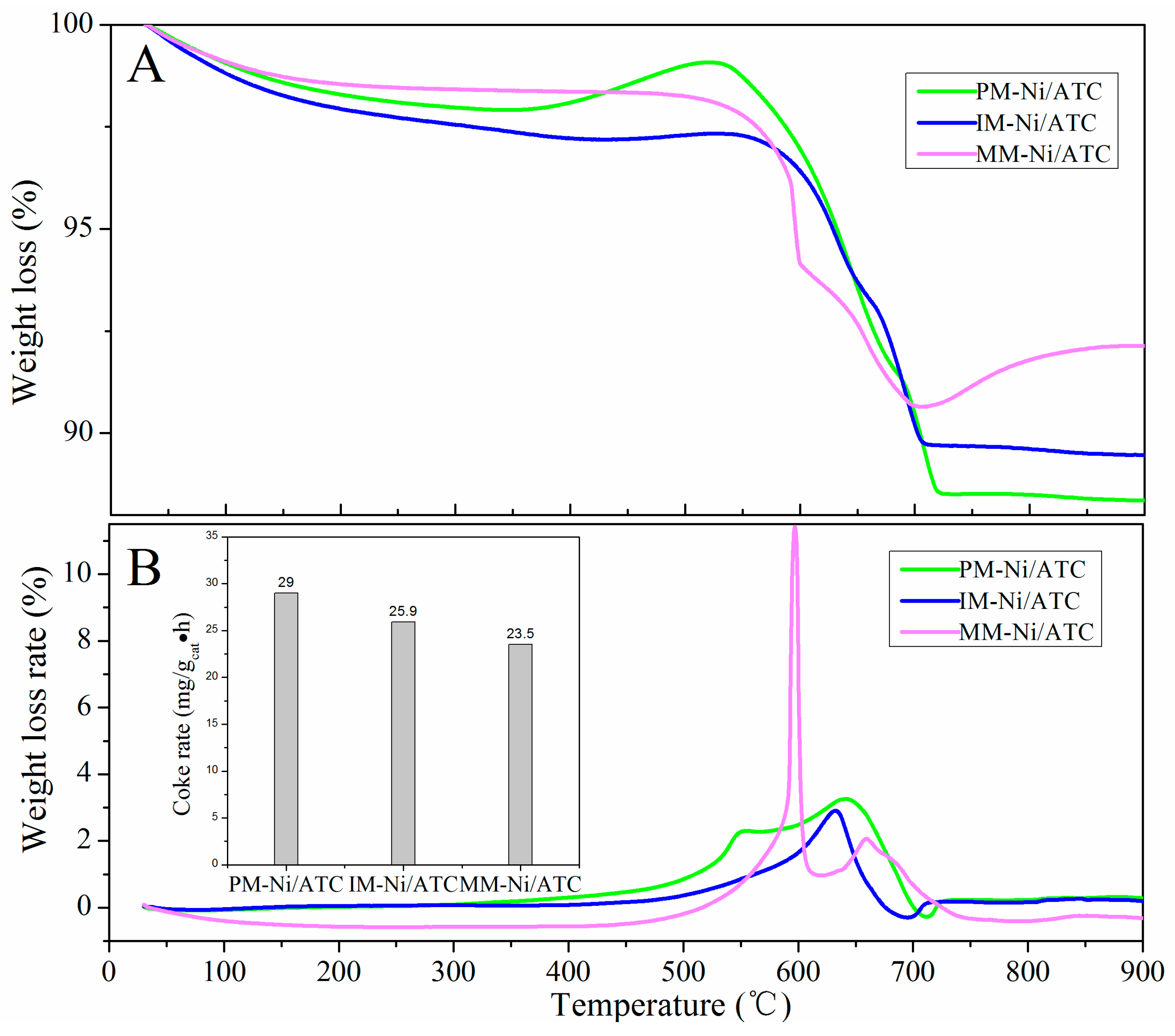
2.3.1. Thermogravimetric Analysis of Spent Catalysts

Thermogravimetric Analysis (TGA) was employed to measure the weight loss caused by the elimination of coke deposits. The carbon deposition on the three catalysts after SRAA reaction for 4 h at 650 °C were investigated by TG-DTG and the results are displayed in Figure 7. It can be seen that significant weight losses happened over the three spent catalysts and their coke rates are larger than 5 mg·(gcat.·h)−1 of Ni/CeO2 [56] but lower than 75 mg·(gcat.·h)−1 of Ni/SiO2 [57], indicating that their variation is in a reasonable range. The coke rates in Figure 7 (inset) show similar results with the literature [52], in which the coke rate varied in a range of 22.5~32.5 mg·(gcat.·h)−1 of Ni/Al2O3. As shown in Figure 7B, all of the used catalysts exhibit obvious peaks from 550 to 700 °C, which are attributed to the combustion of carbon with different graphitization degrees [52,58]. The carbon deposited on spent catalysts has been verified by XRD (Figure 1), in which the diffraction peaks at 26.7° and 29.5° in spent catalysts at 650 °C belong to graphite-like carbon (JCPDS PDF# 41-1487) [58] and chaoite-like carbon (JCPSD PDF# 22-1069) [59]. Figure 7 also shows that the amount of carbon deposition decreases in the following sequence: PM-Ni/ATC > IM-Ni/ATC > MM-Ni/ATC. However, the catalytic activity and stability of the three catalysts decrease in the same sequence, as exhibited in Figure 6. Therefore, the main reason for catalyst deactivation is not the carbon deposition on the catalysts, but the Ni particles grain sintered on the ATC. By comparison among the XRD diffraction patterns of all spent catalysts (Figure 1), it is easy to find that the intensities and peak areas of Ni° characteristic peaks in MM-Ni/ATC catalyst are stronger and larger than those of the other two catalysts. This result could demonstrate that the Ni particles sintering in MM-Ni/ATC catalyst are more serious than the others, so its activity and stability are the lowest among all three catalysts. A similar result was found by Xu et al. [60].

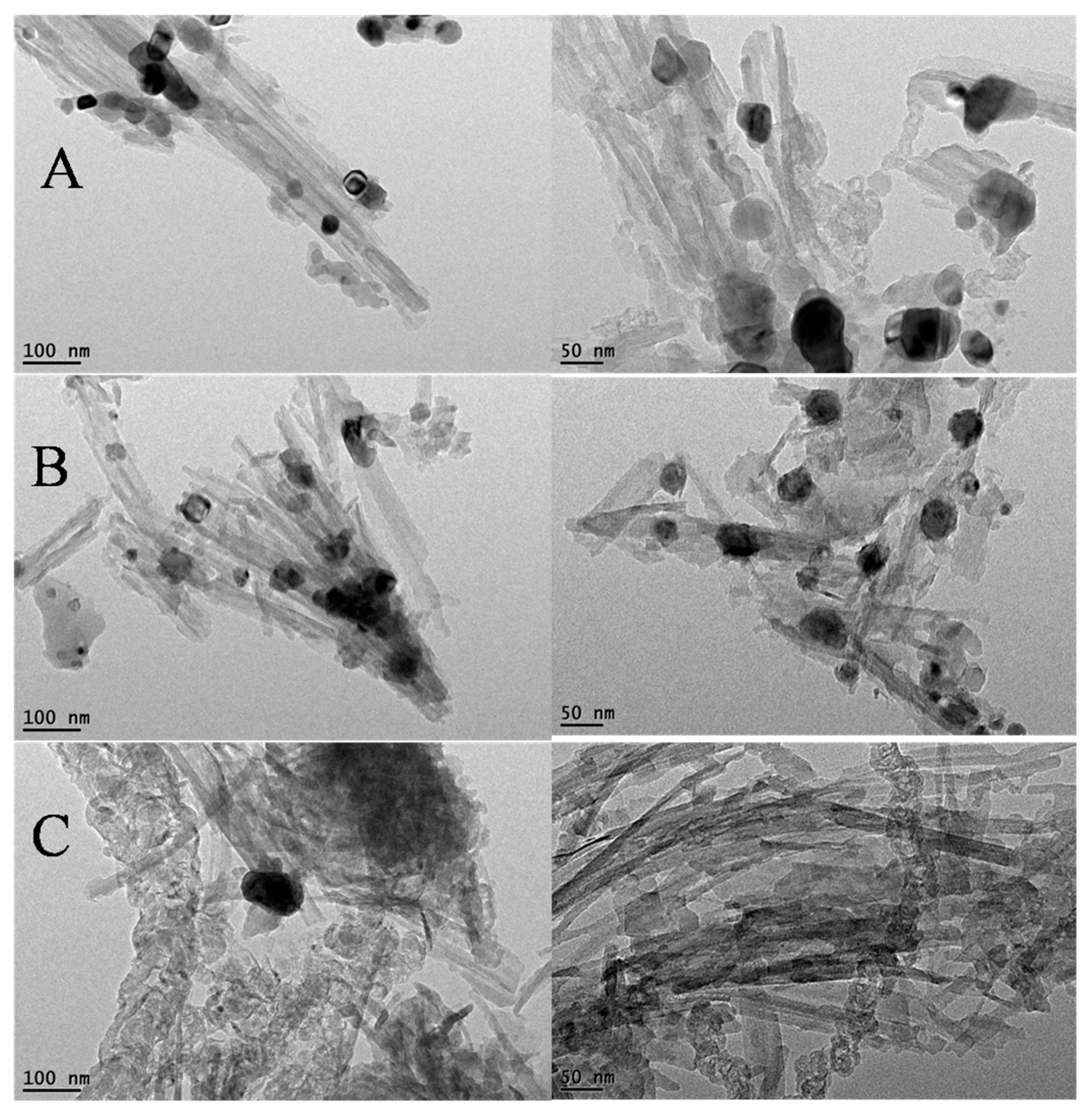
2.3.2. TEM Analysis of Spent Catalysts

In order to further study the sintered Ni particles in all spent catalysts, TEM analysis has been employed, and the TEM images of spent catalysts are shown in Figure 8. As can be seen, all spent catalysts show some amount of fiber-shape and coating carbon, which could block and cover nickel species active sites resulting in gradual deactivation of catalysts [52]. From the results shown in Figure 8, it can also be seen that the fiber-like shapes of PM-Ni/ATC and IM-Ni/ATC do not change compared with their reduced formation (Figure 3), and the Ni particles of them slightly increase but are still below 35 nm, as shown in Table 3. Li et al. [17] had found the Ni particle size below 35 nm on the surface of ZrO2 had an outstanding activity for SRAA. Thus, PM-Ni/ATC and IM-Ni/ATC catalysts have a significant activity and stability among all catalysts (Figure 6). However, the morphology of PM-Ni/ATC has an obvious change, where some caking and agglomeration emerge on its surface. Furthermore, the mean of Ni particle size of used MM-Ni/ATC catalyst is 83.1 nm (Table 3) and it is larger than that of reduced MM-Ni/ATC and those of other two spent catalysts. This result demonstrates that the Ni particles on the surface of MM-Ni/ATC suffer from severe aggregation and sintering during the SRAA reaction, resulting in the significant deactivation of MM-Ni/ATC catalyst. That is to say, the sintering of active component in the carrier surface is the main reason causing catalyst deactivation.

3. Experiment Methods

3.1. Preparation of Catalysts

In this research, all chemicals were purchased from Sinopharm Chemical Reagent Co., Ltd. (Shanghai, China) and were analytical grade. ATC, which was collected from SuZhou of AnHui Province, was purified and pretreated in our laboratory. For precipitation synthesis method, 17.07 g of Ni(NO3)2·6H2O was dissolved in 100 mL of distilled water under vigorous stirring at 80 °C together with 20.00 g of ATC powder to form suspension liquid (labeled as A). After that, a certain amount of 4 mol/L of hartshorn (NH4OH), as precipitant, was added dropwise into A until the pH reached 7~8 and stirred vigorously for 12 h at 80 °C, then kept ageing for 24 h, filtered and washed with distilled water to form precursor. For impregnation synthesis method, the synthesis method of suspension liquid A was the same as that of precipitation method. After that the suspension liquid A kept under agitation for 36 h at 80 °C, then it was placed into rotary evaporators and the extra water was evaporated to form precursor. For mechanical blending method, 17.07 g of Ni(NO3)2·6H2O and 20.00 g of ATC powder together with a little amount of anhydrous ethanol were added into an agate jar assembled in ND7-1L ball grinder (Nanjing Tianzhun Electronics co., LTD, Nanjing, China) for being grounded for 12 h at a revolving speed of 200 r/min, after that the suspension was washed and filtered with distilled water to form precursor.
These three precursors were dried in drying oven (Changzhou Dingbang Minerals Technology Co., LTD, Changzhou, China) at 110 °C for 12 h and then were calcined in tube furnace (Hefei Kejing Materials Technology Co., LTD, Hefei, China) at 550 °C for 2 h with a heating rate of 2°/min. At the end of the above processes, three kinds of fresh NiO/ATC catalysts were synthetized and were labeled as PM-Ni/ATC (precipitation method), IM-Ni/ATC (impregnation method) and MM-Ni/ATC (mechanical blending method). The nominal mass ratio of NiO:ATC in three catalysts was 18:82. The actual surface chemical composition of all catalysts was detected by EDX (Energy Dispersive X-ray Spectrum) (Suzhou Deyou Boce New Material Co., LTD, Suzhou, China). The results are shown in Table 4. It can be seen that the actual content of NiO is consistent with the nominal contain.

3.2. Characterizations

X-ray diffraction (XRD) patterns were obtained on Hao Yuan DX-2800 X-ray diffractometer (Dan Dong, China), using Cu-Kα radiation (λ = 1.5406 Å, 40 kV, 30 mA) in the range of 2θ from 10° to 70° at scanning step of 0.03°. The specific surface areas and the N2 adsorption–desorption isotherms were measured by ASAP2020 surface area and porosity analyzer (Micromeritics Instrument Corp., Norcross, GA, USA) at liquid nitrogen temperature (77 K). Before detection, the samples were treated at 250 °C for 4 h under nitrogen to eliminate impurities. The morphology of reduced and spent catalysts was observed by high-resolution transmission electron microscope (HRTEM) (Suzhou Deyou Boce new material Co., LTD, Suzhou, China) with FEI Tecnai G2 F20 S-Twin electron microscope (FEI, Hillsboro, OR, USA). Size distribution of active metal (Ni) particles was determined by the software of nano measurer 1.2 (Beijing Zhongke Baice Technology Service Co., LTD, Beijing, China), and the means of Ni particle sizes of catalysts were calculated by the measurement of more than 100 particles obtained from several selected TEM images.
Hydrogen temperature programmed reduction (H2-TPR) measurements were performed on PengXiang PX200 chemical adsorption instrument (TianJin, China) equipped with a thermal conductivity detector (TCD) (Shanghai Huaai Chromatography, Shanghai, China). Seventy milligrams of sample was added into the bed-reactor, which was reduced by using a 5% H2/Ar (v/v) mixture flowing of 40 mL·min−1 for each measurement, and the reaction temperature was raised from normal temperature to 900 °C at a heating rate of 10 °C·min−1.
The coke deposition on spent catalyst was determined by thermogravimetric analysis (TGA) using a TGA/DSC1 STARe System instrument (Mettler-Toledo, Greifensee, Switzerland) The spent catalysts were heated from ambient temperature to 900 °C at a heating rate of 10 °C·min−1 under air (50 mL·min−1).

3.3. Catalytic Performance Test

The process of SRAA was conducted in a continuous-flow fix-bed tubular reactor (I.D. 30 mm) (Hefei Kejing Materials Technology Co., LTD, Hefei, China) under ambient pressure at 550 °C and 650 °C. Typically, 3.00 g fresh catalyst was placed at the center of stainless steel tubular, and reduced in situ in a 10% H2/N2 flow rate of 0.32 L/min at 600 °C for 2 h before reaction. The mixture of AC and water with a molar ratio of 1:6 was vaporized at 300 °C by pre-heater, mixed with an high purity N2 (Nanjing Special Gas Factory Co., Ltd., Nanjing, China) and fed into tubular reactor with a molar ratio of AA:H2O:N2 = 1:6:7.62 at 1.68 g-AA/(g-catalyst·h) under 550 °C and 650 °C. The produced gas was collected by gas collecting bag and analyzed by using an off-line gas chromatography (GC-9160, Shanghai Huaai Chromatography Analysis Co., Ltd., Shanghai, China) equipped with TCD detectors. The sensitivity of TCD detector is S ≥ 2500 mV·mL/mg (Hexadecane).
On the basis of elemental balance, the conversion of AA (XAA), the yield of H2 (YH2) and selectivity of carbon-containing products (Si) could be calculated with the following equations [61]:
n out , dry = n N 2 1 y i y H 2
X AA ( % ) = n out , dry × y i 2 n AA , in × 100
Y H 2 ( % ) = n out , dry × y H 2 4 n AA , in × 100
S i ( % ) = n out , dry × y i 2 n AA , in × X AA × 100
In the above equations, nout,dry is the molar flow rate of total dry outlet gas; yi and yH2 are the mole percent of i species (such as CH4, CO and CO2) and H2, respectively; and nN2 and nAA,in are the molar flow rate of N2 and AA fed in reactor, respectively.

4. Conclusions

In this study, Ni/ATC (attapulgite clay) catalysts were prepared using three different preparation methods (precipitation, impregnation and mechanical blending). From the characterizations of fresh and reduced catalysts, it is found that precipitation method could enhance the interaction between active component and carrier and promote the Ni particles dispersion on the surface, which resulted in the Ni/ATC catalyst having relatively high AA conversion (85%), the highest H2 yield (83%) and outstanding stability during SRAA reaction at 650 °C. In addition, it is also found that catalyst deactivation was not caused by the amount of carbon deposition, but owed to the significant agglomeration and sintering of Ni particles in the carrier. Therefore, the strong interaction between Ni species and ATC supporter could be achieved through precipitation method. The precipitation method further enhances the activity and stability of Ni/ATC catalyst.

Acknowledgments

The authors thank the National Science Foundation of China (21376007), National Science and Technology Support Project of China (2014BAD02B03) and Anhui province natural science foundation of China (1608085ME90) for the financial support.

Author Contributions

Y.W. and Q.C. conceived and designed the project. S.M. and Z.L. participated in the analysis and interpretation of characterization results. J.Y. performed catalysts synthesis. L.T. carried out catalyst characterization and evaluation. The manuscript was written through the contribution of all authors. All authors approved the final version of the manuscript.

Conflicts of Interest

The authors declare no conflict of interest.

References

  1. Song, C. Global challenges and strategies for control, conversion and utilization of CO2, for sustainable development involving energy, catalysis, adsorption and chemical processing. Catal. Today 2006, 115, 2–32. [Google Scholar] [CrossRef]
  2. Goltsov, V.A.; Veziroglu, T.N.; Goltsova, L.F. Hydrogen civilization of the future—A new conception of the IAHE. Int. J. Hydrog. Energy 2006, 31, 153–159. [Google Scholar] [CrossRef]
  3. Centi, G.; Perathoner, S. Opportunities and prospects in the chemical recycling of carbon dioxide to fuels. Catal. Today 2009, 148, 191–205. [Google Scholar] [CrossRef]
  4. Hosseini, S.E.; Wahid, M.A. Hydrogen Production from Renewable and Sustainable Energy Resources: Promising Green Energy Carrier for Clean Development. Renew. Sustain. Energy Rev. 2015, 57, 850–866. [Google Scholar] [CrossRef]
  5. Ayalur Chattanathan, S.; Adhikari, S.; Abdoulmoumine, N. A review on current status of hydrogen production from bio-oil. Renew. Sustain. Energy Rev. 2012, 16, 2366–2372. [Google Scholar] [CrossRef]
  6. Trane, R.; Dahl, S.; Skjøth-Rasmussen, M.S.; Jensen, A.D. Catalytic steam reforming of bio-oil. Int. J. Hydrog. Energy 2012, 37, 6447–6472. [Google Scholar] [CrossRef]
  7. Chen, T.; Wu, C.; Liu, R. Steam reforming of bio-oil from rice husks fast pyrolysis for hydrogen production. Bioresour. Technol. 2011, 102, 9236–9240. [Google Scholar] [CrossRef] [PubMed]
  8. Garcia, L.; French, R.; Czernik, S.; Chornet, E. Catalytic steam reforming of bio-oils for the production of hydrogen: Effects of catalyst composition. Appl. Catal. A Gen. 2000, 201, 225–239. [Google Scholar] [CrossRef]
  9. Galdámez, J.R.; García, L.; Bilbao, R. Hydrogen Production by Steam Reforming of Bio-Oil Using Coprecipitated Ni–Al Catalysts. Acetic Acid as a Model Compound. Energy 2005, 19, 1133–1142. [Google Scholar] [CrossRef]
  10. Park, H.J.; Heo, H.S.; Jeon, J.K.; Kim, J.; Ryoo, R. Highly valuable chemicals production from catalytic upgrading of radiata pine sawdust-derived pyrolytic vapors over mesoporous MFI zeolites. Appl. Catal. B Environ. 2010, 95, 365–373. [Google Scholar] [CrossRef]
  11. Nava, R.; Pawelec, B.; Castaño, P.; Alvarez-Galvan, M.C.; Loricera, C.V.; Fierro, J.L.G. Upgrading of bio-liquids on different mesoporous silica-supported CoMo catalysts. Appl. Catal. B Environ. 2009, 92, 154–167. [Google Scholar] [CrossRef]
  12. Luo, Z.Y.; Wang, S.R.; Liao, Y.F.; Zhou, J.S.; Gu, Y.L.; Cen, K.F. Research on biomass fast pyrolysis for liquid fuel. Biomass Bioenergy 2004, 26, 455–462. [Google Scholar] [CrossRef]
  13. Resende, K.A.; Ávila-Neto, C.N.; Rabelo-Neto, R.C.; Noronha, F.B.; Hori, C.E. Hydrogen production by reforming of acetic acid using La–Ni type perovskites partially substituted with Sm and Pr. Catal. Today 2015, 242, 71–79. [Google Scholar] [CrossRef]
  14. Hu, X.; Lu, G.X. Comparative study of alumina-supported transition metal catalysts for hydrogen generation by steam reforming of acetic acid. Appl. Catal. B Environ. 2010, 99, 289–297. [Google Scholar] [CrossRef]
  15. Goicoechea, S.; Kraleva, E.; Sokolov, S.; Schneider, M.; Pohl, M.M.; Kockmann, N.; Ehrich, H. Support effect on structure and performance of Co and Ni catalysts for steam reforming of acetic acid. Appl. Catal. A Gen. 2016, 514, 182–191. [Google Scholar] [CrossRef]
  16. Assaf, P.G.M.; Nogueira, F.G.E.; Assaf, E.M. Ni and Co catalysts supported on alumina applied to steam reforming of acetic acid: Representative compound for the aqueous phase of bio-oil derived from biomass. Catal. Today 2013, 213, 2–8. [Google Scholar] [CrossRef]
  17. Li, Z.K.; Hu, X.; Zhang, L.J.; Liu, S.M.; Lu, G.X. Steam reforming of acetic acid over Ni/ZrO2 catalysts: Effects of nickel loading and particle size on product distribution and coke formation. Appl. Catal. A Gen. 2012, 417, 281–289. [Google Scholar] [CrossRef]
  18. Vagia, E.C.; Lemonidou, A.A. Investigations on the properties of ceria-zirconia-supported Ni and Rh catalysts and their performance in acetic acid steam reforming. J. Catal. 2010, 269, 388–396. [Google Scholar] [CrossRef]
  19. Thaicharoensutcharittham, S.; Meeyoo, V.; Kitiyanan, B.; Rangsunvigit, P.; Rirksomboon, T. Hydrogen production by steam reforming of acetic acid over Ni-based catalysts. Catal. Today 2011, 164, 257–261. [Google Scholar] [CrossRef]
  20. Wang, S.R.; Li, X.B.; Long, G.; Luo, Z.Y. Experimental research on acetic acid steam reforming over Co-Fe catalysts and subsequent density functional theory studies. Int. J. Hydrog. Energy 2012, 37, 11122–11131. [Google Scholar] [CrossRef]
  21. Hu, X.; Lu, G. Acetic acid steam reforming to hydrogen over Co-Ce/Al2O3 and Co-La/Al2O3 catalysts-The promotion effect of Ce and La addition. Catal. Commun. 2010, 12, 50–53. [Google Scholar] [CrossRef]
  22. Mohanty, P.; Patel, M.; Pant, K.K. Hydrogen production from steam reforming of acetic acid over Cu-Zn supported calcium aluminate. Bioresour. Technol. 2012, 123, 558–565. [Google Scholar] [CrossRef] [PubMed]
  23. Zhang, F.B.; Wang, N.; Yang, L.; Li, M.; Huang, L.H. Ni-Co bimetallic MgO-based catalysts for hydrogen production via steam reforming of acetic acid from bio-oil. Int. J. Hydrog. Energy 2014, 39, 18688–18694. [Google Scholar] [CrossRef]
  24. Zhong, X.Y.; Xie, W.; Wang, N.; Duan, Y.P.; Shang, R.S.; Huang, L.H. Dolomite-Derived Ni-Based Catalysts with Fe Modification for Hydrogen Production via Auto-Thermal Reforming of Acetic Acid. Catalysts 2016, 6, 85. [Google Scholar] [CrossRef]
  25. Basagiannis, A.C.; Verykios, X.E. Reforming reactions of acetic acid on nickel catalysts over a wide temperature range. Appl. Catal. A Gen. 2006, 308, 182–193. [Google Scholar] [CrossRef]
  26. Esteves, L.M.; Brijaldo, M.H.; Passos, F.B. Decomposition of acetic acid for hydrogen production over Pd/Al2O3 and Pd/TiO2: Influence of metal precursor. J. Mol. Catal. A Chem. 2016, 442, 275–288. [Google Scholar] [CrossRef]
  27. Brijaldo, M.H.; Rojas, H.A.; Martínez, J.J.; Passos, F.B. Effect of support on acetic acid decomposition over palladium catalysts. J. Catal. 2015, 331, 63–75. [Google Scholar] [CrossRef]
  28. Takanabe, K.; Aika, K.I.; Seshan, K.; Lefferts, L. Catalyst deactivation during steam reforming of acetic acid over Pt/ZrO2. Chem. Eng. J. 2006, 120, 133–137. [Google Scholar] [CrossRef]
  29. Takanabe, K.; Aika, K.I.; Inazu, K.; Baba, T.; Seshan, K.; Lefferts, L. Steam reforming of acetic acid as a biomass derived oxygenate: Bifunctional pathway for hydrogen formation over Pt/ZrO2 catalysts. J. Catal. 2006, 243, 263–269. [Google Scholar] [CrossRef]
  30. Lemonidou, A.A.; Vagia, E.C.; Lercher, J.A. Acetic Acid Reforming over Rh Supported on La2O3/CeO2–ZrO2: Catalytic Performance and Reaction Pathway Analysis. ACS Catal. 2013, 3, 1919–1928. [Google Scholar] [CrossRef]
  31. Basagiannis, A.C.; Verykios, X.E. Influence of the carrier on steam reforming of acetic acid over Ru-based catalysts. Appl. Catal. B Environ. 2008, 82, 77–88. [Google Scholar] [CrossRef]
  32. Bimbela, F.; Oliva, M.; Ruiz, J.; Garcıa, L.; Arauzo, J. Hydrogen production by catalytic steam reforming of acetic acid, a model compound of biomass pyrolysis liquids. J. Anal. Appl. Pyrolysis 2007, 79, 112–120. [Google Scholar] [CrossRef]
  33. Medrano, J.A.; Oliva, M.; Ruiz, J.; Garcıa, L.; Arauzo, J. Catalytic steam reforming of model compounds of biomass pyrolysis liquids in fluidized bed reactor with modified Ni/Al catalysts. J. Anal. Appl. Pyrolysis 2009, 85, 214–225. [Google Scholar] [CrossRef]
  34. Ma, H.Y.; Zeng, L.; Tian, H.; Li, D.; Wang, X.; Li, X.Y.; Gong, J.L. Efficient hydrogen production from ethanol steam reforming over La-modified ordered mesoporous Ni-based catalysts. Appl. Catal. B Environ. 2016, 181, 321–331. [Google Scholar] [CrossRef]
  35. Fermoso, J.; Gil, M.V.; Rubiera, F.; Chen, D. Multifunctional Pd/Ni-Co Catalyst for Hydrogen Production by Chemical Looping Coupled With Steam Reforming of Acetic Acid. Chemsuschem 2014, 7, 3063–3077. [Google Scholar] [CrossRef] [PubMed]
  36. Rossetti, I.; Lasso, J.; Finocchio, E.; Ramis, G.; Nichele, V.; Signoretto, M.; Michele, A.D. TiO2-supported catalysts for the steam reforming of ethanol. Appl. Catal. A Gen. 2014, 477, 42–53. [Google Scholar] [CrossRef]
  37. Wang, Y.S.; Chen, M.Q.; Liu, S.M.; Yang, Z.L.; Shen, C.P.; Liu, K. Hydrogen production via catalytic steam reforming of bio-oil model compounds over NiO-Fe2O3-loaded palygouskite. J. Fuel Chem. Technol. 2015, 43, 1470–1475. [Google Scholar]
  38. Dancini-Pontes, I.; Desouza, M.; Silva, F.A.; Scaliante, M.H.N.O.; Alonso, C.G.; Bianchi, G.S.; Neto, A.M.; Pereira, G.M.; Fernandes-Machado, N.R.C. Influence of the CeO2 and Nb2O5 supports and the inert gas in ethanol steam reforming for H2 production. Chem. Eng. J. 2015, 273, 66–74. [Google Scholar] [CrossRef]
  39. Nichele, V.; Signoretto, M.; Pinna, F.; Menegazzo, F.; Rossetti, I.; Cruciani, G.; Cerrato, G.; Michele, A.D. Ni/ZrO2 catalysts in ethanol steam reforming: Inhibition of coke formation by CaO-doping. Appl. Catal. B Environ. 2014, 150–151, 12–20. [Google Scholar] [CrossRef]
  40. Haryanto, A.; Fernando, S.; Murali, N.; Adhikari, S. Current Status of Hydrogen Production Techniques by Steam Reforming of Ethanol: A Review. Energy Fuels 2005, 19, 2098–2106. [Google Scholar] [CrossRef]
  41. Luo, X.; Hong, Y.; Wang, F.C.; Hao, S.Q.; Pang, C.H.; Lester, E.; Wu, T. Development of nano NixMgyO solid solutions with outstanding anti-carbon deposition capability for the steam reforming of methanol. Appl. Catal. B Environ. 2016, 194, 84–97. [Google Scholar] [CrossRef]
  42. Silva, F.A.D.; Pontes, I.D.; Wurzler, G.T.; Alonso, C.G.; Neto, A.M.; Scaliante, M.H.N.; Souza, M.D.; Fernandes-Machado, N.R.C. Production of hydrogen from bioethanol in Cu-Ni/NbxOy catalysts obtained by different preparation methods. Int. J. Hydrog. Energy 2016, 41, 8111–8119. [Google Scholar] [CrossRef]
  43. Sun, Z.M.; Bai, C.H.; Zheng, S.L.; Yang, X.P.; Frost, R.L. A comparative study of different porous amorphous silica minerals supported TiO2 catalysts. Appl. Catal. A Gen. 2013, 458, 103–110. [Google Scholar] [CrossRef] [Green Version]
  44. Fagherazzi, G.; Benedetti, A.; Polizzi, S.; Mario, A.D.; Pinna, F.; Signoretto, M.; Pernicone, N. Structural investigation on the stoichiometry of β-PdHx in Pd/SiO2 catalysts as a function of metal dispersion. Catal. Lett. 1995, 32, 293–303. [Google Scholar] [CrossRef]
  45. Asencios, Y.J.O.; Rodella, C.B.; Assaf, E.M. Oxidative reforming of model biogas over NiO-Y2O3-ZrO2 catalysts. Appl. Catal. B Environ. 2013, 132–133, 1–12. [Google Scholar] [CrossRef]
  46. Nogueira, F.G.E.; Assaf, P.G.M.; Carvalho, H.W.P.; Assaf, E.M. Catalytic steam reforming of acetic acid as a model compound of bio-oil. Appl. Catal. B Environ. 2014, 160–161, 188–199. [Google Scholar] [CrossRef]
  47. Cao, J.L.; Shao, G.S.; Wang, Y.; Liu, Y.P.; Yuan, Z.Y. CuO catalysts supported on attapulgite clay for low-temperature CO oxidation. Catal. Commun. 2008, 9, 2555–2559. [Google Scholar] [CrossRef]
  48. Yuan, Z.Y.; Ren, T.Z.; Vantomme, A.; Su, B.L. Facile and Generalized Preparation of Hierarchically Mesoporous-Macroporous Binary Metal Oxide Materials. Chem. Mater. 2004, 16, 5096–5106. [Google Scholar] [CrossRef]
  49. Li, X.Y.; Zhang, D.Y.; Liu, X.Q.; Shi, L.Y.; Sun, L.B. A tandem demetalization-desilication strategy to enhance the porosity of attapulgite for adsorption and catalysis. Chem. Eng. Sci. 2015, 141, 184–194. [Google Scholar] [CrossRef]
  50. Li, X.Z.; Hu, Z.L.; Zhao, X.B.; Lu, X.W. Ce1−xSmxO2−δ-attapulgite nanocomposites: Synthesis via simple microwave approach and investigation of its catalytic activity. J. Rare Earths 2013, 31, 1157–1162. [Google Scholar] [CrossRef]
  51. Chary, K.V.R.; Rao, P.V.R.; Vishwanathan, V. Synthesis and high performance of ceria supported nickel catalysts for hydrodechlorination reaction. Catal. Commun. 2006, 7, 974–978. [Google Scholar] [CrossRef]
  52. Wang, T.; Ma, H.Y.; Zeng, L.; Li, D.; Tian, H.; Xiao, S.N.; Gong, J.L. Highly loaded Ni-based catalysts for low temperature ethanol steam reforming. Nanoscale 2016, 8, 10177–10187. [Google Scholar] [CrossRef] [PubMed]
  53. Bengaard, H.S.; Nørskov, J.K.; Sehested, J.; Clausen, B.S.; Nielsen, L.P.; Molenbroke, A.M.; Rostrup-Nielsen, J.R. Steam Reforming and Graphite Formation on Ni Catalysts. J. Catal. 2002, 209, 365–384. [Google Scholar] [CrossRef]
  54. Yang, X.X.; Wang, Y.J.; Wang, Y.H. Significantly Improved Catalytic Performance of Ni-Based MgO Catalyst in Steam Reforming of Phenol by Inducing Mesostructure. Catalysts 2015, 5, 1721–1736. [Google Scholar] [CrossRef]
  55. Cheng, F.; Dupont, V. Nickel catalyst auto-reduction during steam reforming of bio-oil model compound acetic acid. Int. J. Hydrog. Energy 2013, 38, 15160–15172. [Google Scholar] [CrossRef]
  56. Zhang, C.X.; Li, S.R.; Wu, G.W.; Gong, J.L. Synthesis of stable Ni-CeO2 catalysts via ball-milling for ethanol steam reforming. Catal. Today 2014, 233, 53–60. [Google Scholar] [CrossRef]
  57. Vicente, J.; Ereña, J.; Montero, C.; Azkoiti, M.J.; Bibao, J.; Gayubo, A.G. Reaction pathway for ethanol steam reforming on a Ni/SiO2 catalyst including coke formation. Int. J. Hydrog. Energy 2014, 39, 18820–18834. [Google Scholar] [CrossRef]
  58. Calles, J.A.; Carrero, A.; Vizcaíno, A.J.; García-Moreno, L. Hydrogen production by glycerol steam reforming over SBA-15-supported nickel catalysts: Effect of alkaline earth promoters on activity and stability. Catal. Today 2014, 227, 198–206. [Google Scholar] [CrossRef]
  59. Li, S.D.; Ji, G.B.; Huang, Z.G.; Zhang, F.M.; Du, Y.W. Synthesis of chaoite-like macrotubes at low temperature and ambient pressure. Carbon 2007, 45, 2946–2950. [Google Scholar] [CrossRef]
  60. Xu, Q.L.; Lan, P.; Zhang, B.Z.; Ren, Z.Z.; Yan, Y.J. Hydrogen Production via Catalytic Steam Reforming of Fast Pyrolysis Bio-oil in a Fluidized-Bed Reactor. Energy Fuels 2010, 24, 6456–6462. [Google Scholar] [CrossRef]
  61. Pimenidou, P.; Rickett, G.; Dupont, V.; Twigg, M.V. Chemical looping reforming of waste cooking oil in packed bed reactor. Bioresour. Technol. 2010, 101, 6389–6397. [Google Scholar] [CrossRef] [PubMed]
Figure 1. XRD patterns of fresh, reduced and spent catalysts: (A) PM-Ni/ATC (Attapulgite Clay); (B) IM-Ni/ATC; and (C) MM-Ni/ATC. Spent-550 and Spent-650: The catalysts after reaction at 550 °C and 650 °C, respectively. (PM, IM and MM are the abbreviation of precipitation method, impregnation method and mechanical blending method, respectively.)
Catalysts 06 00172 g001
Figure 2. N2 adsorption–desorption isotherms (a); and pore size distributions (b) of ATC and fresh catalysts.
Catalysts 06 00172 g002
Figure 3. TEM images and nickel particle size distributions of reduced catalysts: (A) PM-Ni/ATC; (B) IM-Ni/ATC; and (C) MM-Ni/ATC.
Catalysts 06 00172 g003
Figure 4. H2-TPR (Temperature Program Reduction) profiles of nature ATC and all fresh catalysts.
Catalysts 06 00172 g004
Figure 5. The XAA and Y H 2 over ATC at 550 °C and 650 °C respectively. (Reaction conditions: 3.00 g ATC, 550 °C and 650 °C, N2 flow rate of 0.24 L/min, feed flow rate of 14 mL/h, H2O/AA (Acetic acid) molar rate of 6).
Catalysts 06 00172 g005
Figure 6. The catalytic performance of all catalysts: (a) Acetic acid conversion; and (b) H2 yield. Reaction conditions: 3.00 g catalyst, 550 °C and 650 °C, N2 flow rate of 0.24 L/min, feed flow rate of 14 mL/h, H2O/AA molar rate of 6. (PM-Ni/ATC-550 expresses the Ni/ATC catalyst prepared by precipitation method after reaction at 550 °C, and the others are similar with this expression).
Catalysts 06 00172 g006
Figure 7. TG (Thermogravimetry) profiles (A); DTG (Differential Thermal Gravity) profiles (B); and the coke rate (inset) of spent catalysts (the spent catalysts were test for 4 h in the process of SRAA at 650 °C under the following conditions: 3.00 g ATC, N2 flow rate of 0.24 L/min, feed flow rate of 14 mL/h, H2O/AA molar rate of 6).
Catalysts 06 00172 g007
Figure 8. TEM images of spent catalysts: (A) PM-Ni/ATC; (B) IM-Ni/ATC; and (C) MM-Ni/ATC.
Catalysts 06 00172 g008
Table 1. Physical properties of fresh and reduced catalysts.
CatalystsdNi a (nm)Sbet (m2/g)Vpore b (cm3/g)Dpore b (nm)Dm (%)
ATC (Attapulgite Clay)-40.60.1010.5-
(precipitation method) PM-Ni/ATC13.565.20.128.97.5
(impregnation method) IM-Ni/ATC20.265.30.129.15.0
MM-Ni/ATC37.068.90.159.92.7
a Calculated from XRD measurements of reduced catalysts using the Scherrer equation; b Calculated through the BJH (Barrett-Joyner-Halenda) desorption.
Table 2. The means of the XAA and Y H 2 and selectivities to product during 2 h over different catalysts.
CatalystsXAA (%) Y H 2 (%)Selectivity (%)
COCO2CH4
550 °CPM-Ni/ATC61.854.544.848.07.2
IM-Ni/ATC59.643.350.839.110.1
MM-Ni/ATC59.053.354.133.912.0
650 °CPM-Ni/ATC75.067.842.441.715.8
IM-Ni/ATC86.570.936.139.124.8
MM-Ni/ATC76.565.440.041.918.1
Reaction conditions: 3.00 g catalyst, 550 °C and 650 °C, N2 flow rate of 0.24 L/min, feed flow rate of 14 mL/h, H2O/AA molar rate of 6.
Table 3. The means of Ni particle sizes (nm) of all reduced and spent catalysts were calculated from TEM.
StatusPM-Ni/ATCIM-Ni/ATCMM-Ni/ATC
Reduced13.017.334.7
Spent23.832.383.1
Table 4. The chemical composition of all samples (wt %).
SamplesSiO2Al2O3CaOMgOK2ONiOFe2O3TiO2
ATC41.65.826.619.41.9/4.00.7
PM-Ni/ATC55.78.73.36.42.418.84.10.6
IM-Ni/ATC51.34.39.513.00.717.53.20.4
MM-Ni/ATC50.66.19.511.30.816.94.10.6

