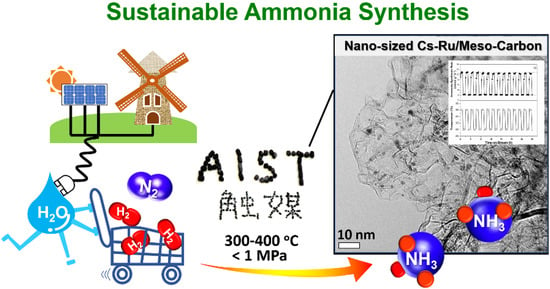
Energy Efficient and Intermittently Variable Ammonia Synthesis over Mesoporous Carbon-Supported Cs-Ru Nanocatalysts


Energy Catalyst Technology Group, Research Institute of Energy Frontier (RIEF), Department of Energy and Environment, National Institute of Advanced Industrial Science and Technology (AIST), 16-1 Onogawa, Tsukuba, Ibaraki 305-8589, Japan
*
Author to whom correspondence should be addressed.
Catalysts 2019, 9(5), 406; https://doi.org/10.3390/catal9050406
Submission received: 9 April 2019
/
Revised: 24 April 2019
/
Accepted: 26 April 2019
/
Published: 30 April 2019
(This article belongs to the Special Issue Catalysis by Precious Metals, Past and Future)
Abstract
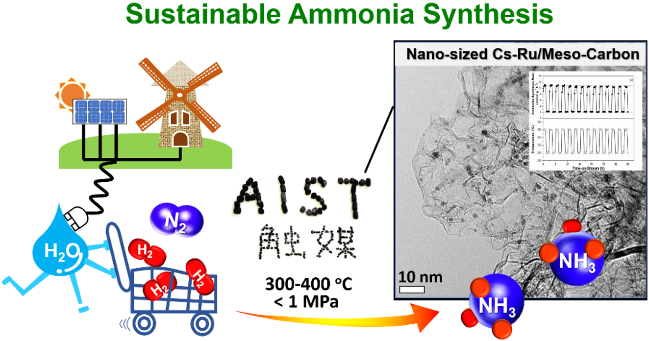
:The Cs-promoted Ru nanocatalysts supported on mesoporous carbon materials (denoted as Cs-Ru/MPC) and microporous activated carbon materials (denoted as Cs-Ru/AC) were prepared for the sustainable synthesis of ammonia under mild reaction conditions (<500 °C, 1 MPa). Both Ru and Cs species were homogeneously impregnated into the mesostructures of three commercial available mesoporous carbon materials annealed at 1500, 1800 and 2100 °C (termed MPC-15, MPC-18 and MPC-21, respectively), resulting in a series of Cs-Ru/MPC catalysts with Ru loadings of 2.5–10 wt % and a fixed Cs loading of 33 wt %, corresponding to Cs/Ru molar ratios of 2.5–10. However, the Ru and Cs species are larger than the pore mouths of microporous activated carbon (shortly termed AC) and, as a consequence, were mostly aggregated on the outer surface of the Cs-Ru/AC catalysts. The Cs-Ru/MPC catalysts are superior to the Cs-Ru/AC catalyst in catalysing mild ammonia synthesis, especially for the 2.5Cs-10Ru/MPC-18 catalyst with a Ru loading of 10 wt % and a Cs/Ru ratio of 2.5, which exhibited the highest activity across a wide SV range. It also showed an excellent response and stability during cycling tests over a severe temperature jump in a short time, presumably due to the open mesoporous carbon framework and suitable surface concentrations of CsOH and metallic Ru species at the catalytically active sites. This 2.5Cs-10Ru/MPC-18 catalyst with high activity, fast responsibility and good stability has potential application in intermittently variable ammonia synthesis using CO2-free hydrogen derived from electrolysis of water using renewable energy with fast variability.
1. Introduction
The latest U.S. Energy Information Administration (EIA) report has projected that the world energy consumption will grow by 28% between 2015 and 2040 due to a continuous increase in human population and improvement in living standards [1]. Fossil fuels will contribute to more than 75% of the energy required through 2040; the inevitable consequence is that large amounts of greenhouse gases (GHGs), especially carbon dioxide (CO2) and particulate matter, would be produced, causing global warming, air pollution and extreme climates. To create a sustainable society with a low carbon economy for future generations, the Paris agreement was adopted in 2015. Its major objective is to limit the increase of global temperature below 2 °C above the pre-industrial levels or if possible, to less than 1.5 °C [2]. Following up on the Paris agreement, Japan promised to reduce 26% of its CO2 emissions by 2030 as compared to those in 2013 and further reduce them by 80% by 2050 as part of its long-term plan [3]. This ambitious goal has motivated scientific research and industrial development in the fields of new energy resources, such as carbon dioxide (CO2)-free hydrogen and energy-effective processes to build a low-carbon society [4]. CO2-free hydrogen can be synthesized by the electrolysis of water using renewable electricity, decomposition of methane combined with carbon capture and storage (CCS) techniques or other well-known methods [5,6]. However, hydrogen is difficult to store, transport and utilize due to its very low boiling point (−252.8 °C), high flammability and price (particularly when hydrogen is produced by renewable energy). These technical problems have hindered the extensive use of hydrogen, especially renewable hydrogen, as a primary energy source.
The incorporation of hydrogen in chemical compounds that can be easily stored, transported and utilized, the so-called hydrogen carriers, is an alternative method to preserve and utilize hydrogen with a high level of safety and security. Ammonia of high hydrogen content (17.6 wt %) and a relatively high boiling point (−33 °C at the standard condition) is a promising hydrogen carrier [7,8,9,10]. The ammonia industry, which had a production capacity of 140 million tons in 2018, is a mature industry with vast infrastructure for the production, storage, transportation and utilization, especially in agriculture and fine chemical chains [11]. However, ammonia is conventionally synthesized by the Haber-Bosch process using Fe3O4-K-Al2O3-based catalysts under severe reaction conditions (>450 °C and 20 MPa), which consumes around 1%–2% of the global energy and releases a massive amount of CO2 (1.2 ton CO2 per ton of NH3) [12,13,14]. Recent studies mainly aim at sustainable ammonia synthesis, catalysed by novel nanostructured materials with enhanced energy efficiency and durability and a reduced carbon footprint under mild conditions using renewable hydrogen as a feedstock. Pioneering works by the Ozaki and Aika research groups and other renowned research groups demonstrated that activated carbon-supported Ru catalysts were superior to conventional Fe-based catalysts in catalysing ammonia synthesis, especially when mild reaction conditions were used [15,16,17,18,19,20,21]. An advanced ammonia synthesis reaction with enhanced energy efficient catalysed by a graphitized carbon-supported Ru-based catalyst was commercialized by Kellogg Brown Root (KBR) in the 1990s; this is the so-called Kellogg Advanced Ammonia Process (KAAP) [22]. The activity of Ru-based catalysts for mild ammonia synthesis can be further improved by the addition of promoters, such as Ce and Ba, or by using new supporting materials with tuneable electronic and structural properties such as the oxides of alkaline, rare-earth elements and transition metals, novel electrolytes and mesoporous carbons with open structures [23,24,25,26,27,28,29,30,31,32]. For example, Ru catalysts supported on Pr2O3 [23] and a composite material of La0.5Ce0.5O1.75 [24] exhibited a higher activity for mild ammonia synthesis than conventional Ru-based catalysts. Novel materials of 12CaO·7Al2O3 and Ba-doped Ca(NH2)2 could be used as supporting materials to fabricate next-generation Ru catalysts for mild ammonia synthesis [25,26]. The recent study further demonstrated that the composite materials of K/Ru/TiO2−xHx were effective in sustainable ammonia synthesis using a solar thermal approach under atmospheric pressure [27]. On the other hand, Cs- and Ba-promoted Ru catalysts supported on microporous carbons with enhanced activity have also been reported for the mild synthesis of ammonia [28,29,30,31]. The microporous carbon-supported Cs-promoted Ru catalysts might be suitable for sustainable ammonia synthesis using a water-rich hydrogen feedstock derived from electrolysis of water powered by renewable energy whereas the deactivation was observed for the Ba-promoted counterparts [32]. However, homogeneous impregnation of nanosized Ru particles into microporous carbons with small pore mouths is a difficult task. The recent study found that the activated carbon-supported Ru catalyst was deactivated seriously during ammonia synthesis due to the sintering of surface Ru particles [33]. This deactivation process can presumably be avoided by replacing activated carbon with mesoporous carbon materials with an open-pore structure at the nanoscale; these mesopores are expected to firmly confine nanosized Ru particles. In addition, mesoporous carbon materials are superior to the analogues of silica and alumina in ammonia synthesis due to their higher electronic properties and structural stability under the reaction conditions [34,35,36,37,38,39,40,41,42,43]. In this study, a series of mesoporous carbon-supported Cs-Ru nanocatalysts with different pore structures and graphite crystallinities were prepared for energy efficient and intermittently variable ammonia synthesis under mild conditions (280–450 °C and <1 MPa); their performance was contrasted with that of a microporous carbon-supported Cs-Ru catalyst. We paid special attention to the influence of the structures of mesoporous carbon supports and the catalytically active sites on the performance of the prepared Cs-Ru catalysts with various Ru loadings and Cs/Ru ratios for mild ammonia synthesis. In addition, ammonia synthesis with rapid changes in the reaction conditions, such as reaction temperature and a wide space velocity (SV) range, was analysed to evaluate the catalytic performance of the prepared Cs-Ru catalysts. Such study is crucial for analysing their potential in intermittently variable ammonia synthesis, where CO2-free hydrogen derived from water electrolysis powered by renewable energy can be used.
2. Results and Discussion
2.1. Characterizations
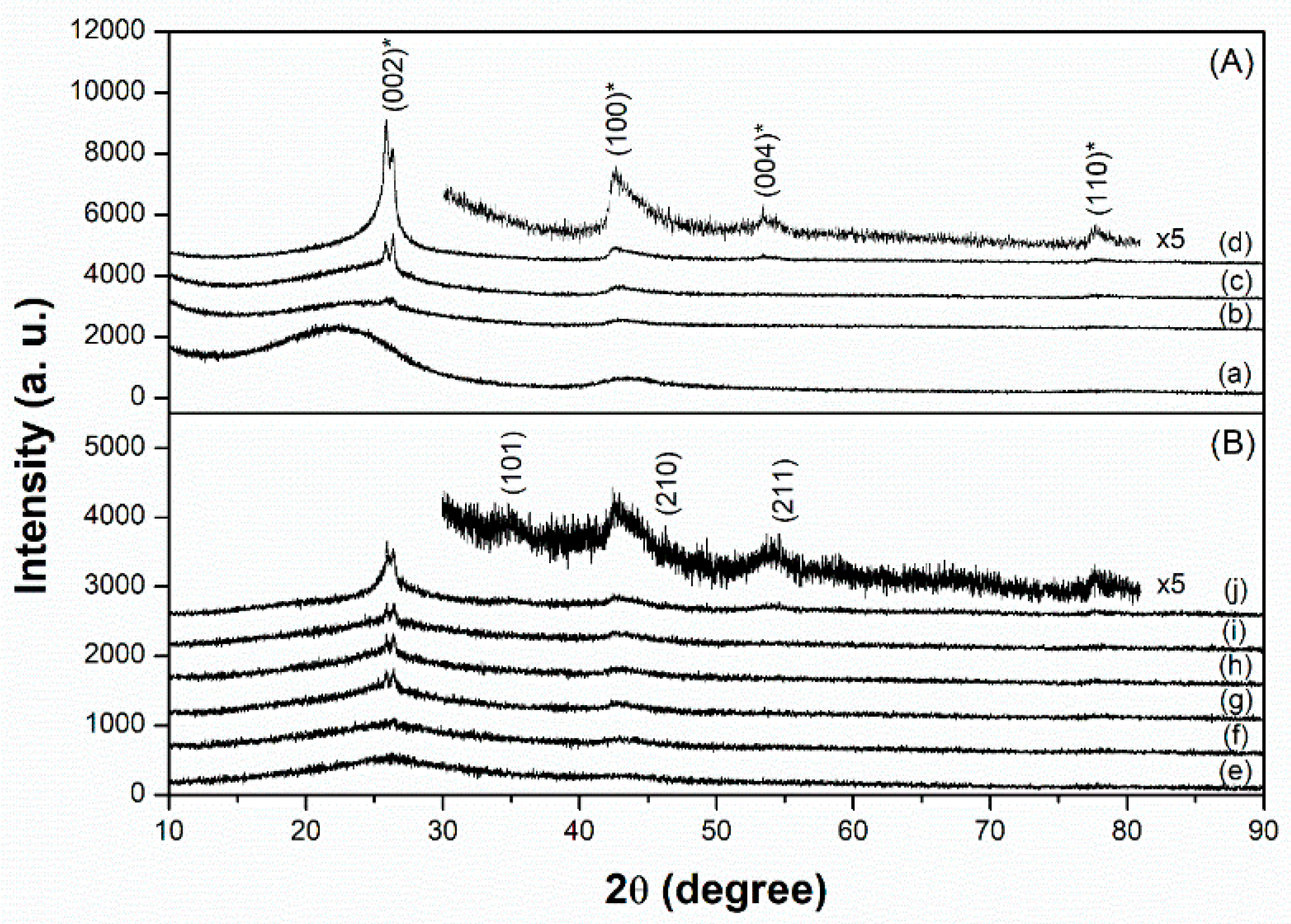
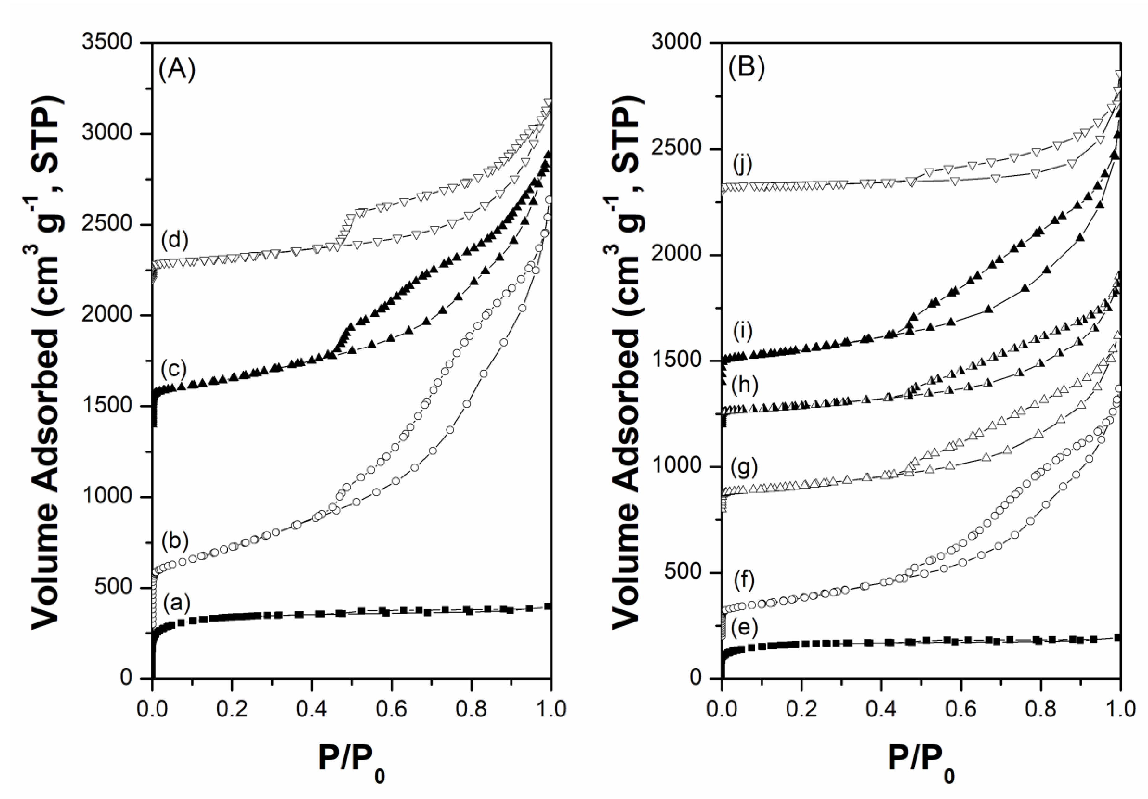
Figure 1 and Figure 2 show the X-ray diffraction (XRD) patterns and N2 adsorption-desorption isotherms of the carbon supports and prepared Cs-Ru catalysts, respectively. In the diffraction patterns of the three MPC supports, several peaks were observed at 25.8°, 26.4°, 42.5°, 53.5° and 77.6°, corresponding to graphite (PDF card number: 9008568). With an increase in annealing temperature, all the diffraction peaks increased to higher values and that of the (002) plane split into two peaks at 25.8° and 26.4°, owing to the growth and crystallization of the mesoporous carbon framework through the heterogeneous graphitization of turbostratic and graphitic structures [44]. In contrast, the AC support exhibits no diffraction peaks in the wide-angle region, suggesting that the carbon framework is amorphous in nature. The N2 physisorption data of the three MPC supports exhibit a classical type IV isotherm with a wide hysteresis loop in a relatively large P/P0 range of 0.5–0.9, corresponding to large mesoporous structures. Meanwhile, the AC support exhibits a classical type I isotherm with no hysteresis loop at relatively high P/P0 regions, indicating the presence of microporous structures with pores smaller than 2 nm.
In the case of the prepared Cs-Ru catalysts, the amount of nitrogen uptake decreased, and the diffraction peaks associated with the graphite structure weakened, indicating that the mesoporous carbon framework is slightly influenced by the thermal treatment used for impregnation. A series of diffraction peaks gradually appear with an increase in the Ru loading, which is associated with the formation of crystalline RuO2 species (PDF card number: 1,000,058). However, no diffraction signals corresponding to the Cs species can be found in the wide-angle XRD patterns. The size of the RuO2 crystallites is too small to be estimated from their diffraction peaks using Scherrer’s equation. This suggests that the Ru and Cs precursors thermally decomposed into nanosized RuO2 particles with low crystallinity (<ca. 5 nm) and amorphous Cs species, respectively, on the carbon materials.
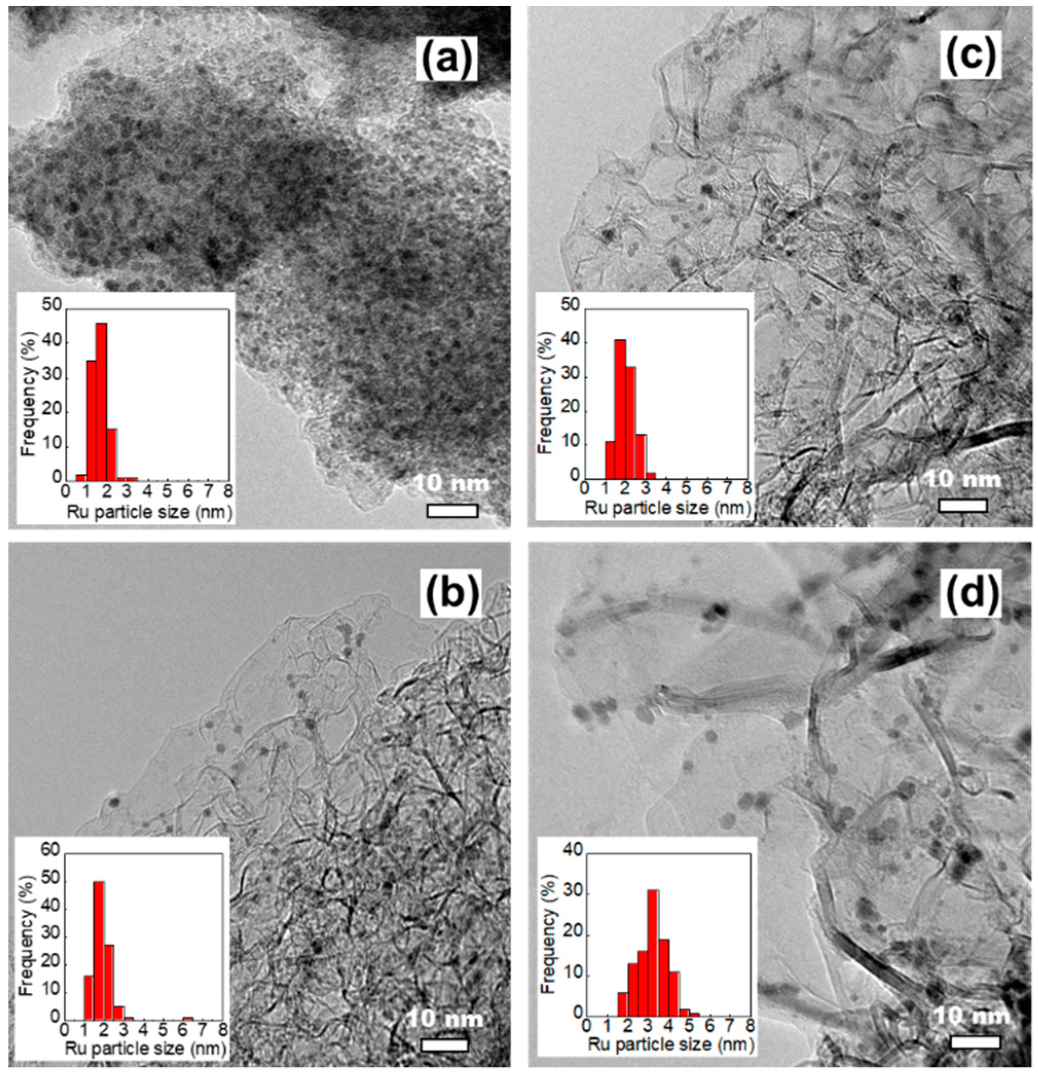
High-resolution transmission electron microscope (HRTEM) and high-angle annular dark-field scanning transmission electron microscopy-scanning transmission electron microscopy (HAADF-STEM) analyses were performed to understand the microstructure of the prepared Cs-Ru catalysts and the sizes and size distributions of Ru and Cs species; the results are compared with those of carbon materials. The MPC supports contain many graphite grains which aggregate to form mesoporous carbon framework with open-pore structure, whereas the AC support contained large aggregates with an amorphous structure and no visible mesopores (Figure S1, electronic supplementary information (ESI)). In the case of the prepared Cs-Ru/MPC catalysts, the HRTEM images in Figure 3b–d show that the dark spots of nanosized RuO2 particles—ca. 2–3 nm in size—are uniformly impregnated into the mesoporous carbon framework with open-pore structure and the influence of the impregnation is hardly found. It should be noted that the dark spots observed in the HRTEM images are mostly Ru particles as supported by the HAADF images (the bright spots in Figures S2–S4, ESI). The size and size distribution of nanosized RuO2 particles increased slightly in the 2.5Cs-10Ru/MPC-21 catalyst, probably due to the decrease in surface area and porosity at high annealing temperatures. The HAADF-STEM images further show that the Cs species are also impregnated into the mesoporous carbon framework and they are presumably accumulated near to nanosized Ru particles (Figures S2–S4, ESI). Microporous carbon-supported Cs-Ru catalysts also contain nanosized RuO2 particles with a narrow size distribution; these particles are surrounded by the Cs species (Figure 3a and Figure S5 (ESI)). However, the Ru particles on the 2.5Cs-10Ru/AC catalyst are close to each other, suggesting that they are presumably impregnated on the outer surface of the AC support.
The structural properties of the carbon materials and the corresponding Cs-Ru catalysts are listed in Table 1. The AC support has a high surface area (SBET = 1260 m2 g−1) and a moderate pore volume (VTotal = 0.62 cm3 g−1), which is mostly related to its microporous structure. In contrast, the MPC supports with mesopores 5–7 nm in size have surface areas of 270–1180 m2 g−1 and pore volumes of 1.28–2.94 cm3 g−1, respectively; such reduced values can be attributed to the growth of graphite structures as the annealing temperature increased. In the prepared Cs-Ru/MPC catalysts, the overall surface area and pore volume decreased upon impregnation; further, the size of the mesopores also varied. In contrast, the pore sizes of AC and 2.5Cs-10Ru/AC are nearly unchanged, which suggests that the Cs and Ru species are mainly impregnated on the outer surface of the AC support. The elemental analysis of carbon, hydrogen and nitrogen (CHN) and the X-ray Fluorescence (XRF) data show that Cs and Ru are indeed impregnated on the MPC and AC supports; however, the Ru loadings and Cs/Ru molar ratios in the fresh samples are slightly different from those of the recipes. It indicates that the compositions and chemical environments of the prepared Cs-Ru catalysts are presumably affected by their nature upon impregnation; however, they are hardly estimated by conventional techniques of CHN elemental and XRF analyses, which are similar to the literature reports [45,46].
By analysing more than 100 particles in the HRTEM images, the RuO2 size and size distribution in 2.5Cs-10Ru/AC, 2.5Cs-10Ru/MPC-15, 2.5Cs-10Ru/MPC-18 and 2.5Cs-10Ru/MPC-21 were found to be (1.6 ± 0.4) nm, (1.9 ± 0.6) nm, (2.1 ± 0.4) nm and (3.2 ± 0.8) nm, respectively; they were found to be inversely proportional to the surface area of the carbon support and Ru loading (Table 2). The HRTEM analysis is consistent with the XRD study, which previously indicated that the RuO2 sizes of the prepared Cs-Ru catalysts should be smaller than 5 nm. The prepared Cs-Ru catalysts with reduction pre-treatment at 450 °C were further studied using the CO chemisorption and CO2-TPD methods. Noted that the reduction pre-treatment was carried out by the same procedure as described in the mild ammonia synthesis. The sizes of metallic Ru nanoparticles calculated by the CO chemisorption method are similar to those by the HRTEM analysis, except the 2.5Cs-10Ru/AC catalyst. The uptakes of CO2 over the prepared Cs-Ru/MPC-18 catalysts are around 2.4–2.7 mmol g−1, which values are smaller than that of the 2.5Cs/MPC-18 catalyst and larger than that of 2.5Cs-10Ru/AC catalyst. In combination with CO chemisorption, CO2-TPD analysis and several characterizations as aforementioned, it can be suggested that nanosized RuO2 particles partially laid on the Cs species can be homogeneously impregnated into the mesoporous carbon framework of MPC supports and they can be reduced to corresponding Ru metals with similar sizes after the reduction pre-treatment. In contrast, the sintering of Ru and Cs species is presumably occurred for those supported on the AC support with microporous carbon framework, suggesting that the Ru and Cs species in the 2.5Cs-10Ru/AC catalyst with microporous carbon framework are relatively unstable.
2.2. Temperature-Programmed Studies
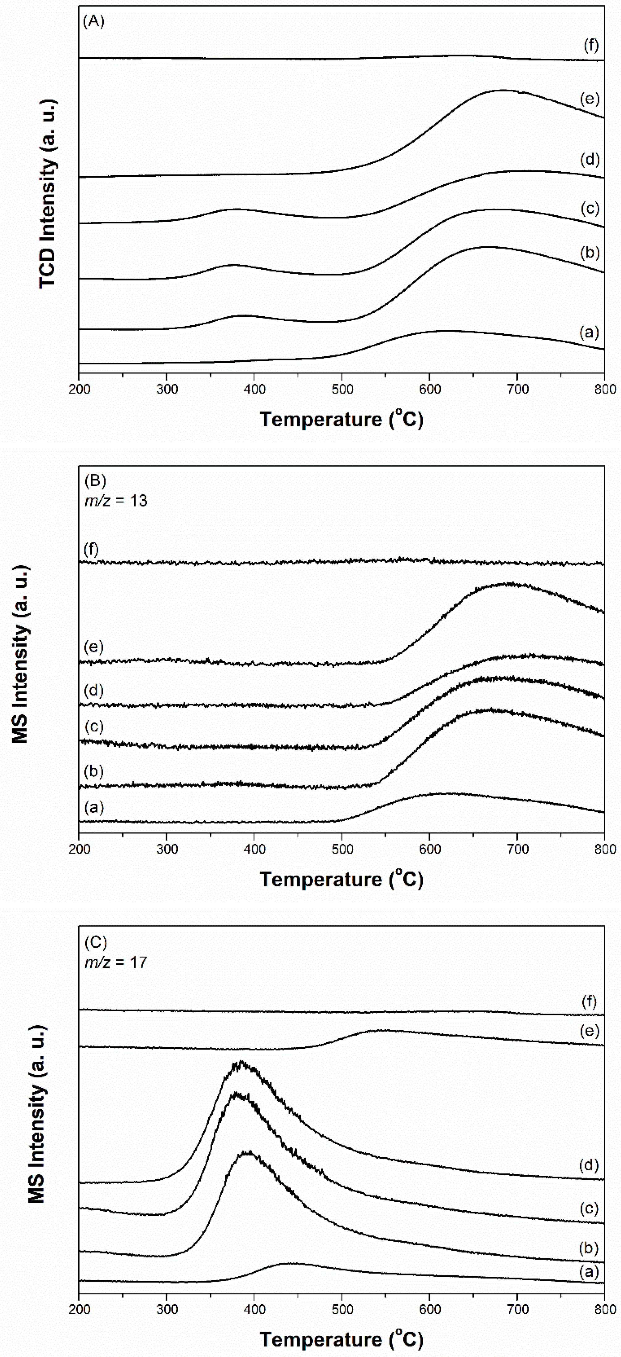
The TPR technique was employed to analyse the compositions and chemical environments of the prepared Cs-Ru catalysts and their nature (i.e. reducibility, activation, stability, etc.) in the reduction atmosphere at ambient pressure. The TPR profiles recorded by TCD are shown in Figure 4A and those recorded by MS are shown in Figure 4B–F) and Figures S10 and S11 (ESI). The TPR profiles of ruthenium oxide (RuO2), MPC-18, 10Ru/MPC-18 and 2.5Cs/MPC-18 as the reference materials were also measured using the same procedures (Figures S6–S9, ESI). No signals could be observed in the MPC-18 sample, suggesting that the unimpregnated mesoporous carbon framework does not react in the reduced environment [47]. A one-step reduction of RuO2 to metallic Ru (Equation (1)) on the RuO2 standard and the 10Ru/MPC-18 sample was observed at temperature below 200 °C [19].
This result once again suggests that RuO2 is formed over the 10Ru/MPC-18 sample by the thermal decomposition of the Ru precursor in an N2 atmosphere, which is consistent with the XRD and HRTEM studies. It should also be noted that the reduction of RuO2 over the 10Ru/MPC-18 sample was observed at relatively low temperatures (ca. 100 °C), suggesting that the nanosized RuO2 species can be easily dispersed on the MPC-18 support and its size is smaller than that of the bulk RuO2 standard. On the other hand, small amounts of CH4 and H2O are gradually formed over the 10Ru/MPC-18 sample in the temperature range of 200–700 °C; this is accompanied by a continuous consumption of small amounts of hydrogen. This observation might be attributed to the methanation of surface oxygenated groups, such as carboxylic acid (-COOH) or carbonyl (-CO) catalysed by the metallic Ru species in the reduction atmosphere to form the clean surface of carbon materials (Equation (2)) [19]. Noted that those superficial oxygenated compounds are presumably formed by surface reaction of nitrate ions and carbon species during the impregnation of Ru(NO)(NO3)3. These gas molecules were only observed by reduction of freshly prepared Cs-Ru catalysts in our study and they were undetectable in the subsequent ammonia synthesis, which will be discussed hereafter. In the industry, the Ru-based catalysts are usually activated at 400–500 °C, which is close to the temperature region of the TPR study as mentioned previously. It speculates that the activation of the Ru-based catalysts used in the ammonia synthesis is not only to form metallic Ru species as the catalytically active sites but also to make metallic Ru species contact with graphite structure of clean surface more. When the temperature is higher than 600 °C, thermal decomposition of the mesoporous carbon framework occurs over 10Ru/MPC-18 and consequently a large amount of CO is formed (Equation (3)) [48]. Similar phenomena are observed for other Cs- and Ru-containing samples, suggesting that the stability of carbon supports in the presences of Cs and Ru species is up to ca. 600 °C under a reduced atmosphere.
RuO2(s) + 2H2(g) → Ru(s) + 2H2O(g)
C(s)-COOH + 4H2(g) → C(s)-H + CH4(s) + 2H2O(g)
C(s)-C=O + 0.5H2(g) → C(s)-H + CO(g)
In the 2.5Cs/MPC-18 sample, desorption of physically adsorbed H2O and CO2 was observed at ca. 100 and 160 °C, respectively. The decomposition of Cs2(CO3) in the presence of H2 to form CsOH and CO2 (Equation (4)) occurred at 350–550 °C [49]. When the temperature was higher than ca. 420 °C, CO and H2O were formed accompanied by a continuous decrease in hydrogen; however, CH4 was not present. This result might be attributed to the decomposition of surface carboxylic groups on the mesoporous carbon framework. The reaction is catalysed by CsOH species in the reduced atmosphere (Equation (5)). It implies that the Cs species might take part in making clean surface of carbon supports, which are able to contact firmly with metallic Ru species after the activation process as mentioned above. Similarly, CO is formed due to the thermal decomposition of mesoporous carbon framework at higher temperatures (Equation (3)).
Cs2(CO3)(s) + H2(g) → 2CsOH(s) + CO2(s)
C(s)-COOH + H2(g) → C(s)-H + CO(g) + H2O(g)
The TPR-TCD and TPR-MS profiles of the prepared Cs-Ru catalysts can be divided into three parts—α, β and γ regions in the temperature ranges of 50–200 °C, 200–550 °C and 550–800 °C, respectively. The positive TCD signal centred at ca. 120–130 °C is due to the reduction of RuO2 to metallic Ru species (Equation (1)); this observation is also supported by the MS signals (α1 in Figure 4B and α3 in Figure 4D corresponding to RuO2(s) + 2H2(g) → Ru(s) + 2H2O(g) (Equation (1), also see Table S1, ESI)). Compared with the 10Ru/MPC-18 sample, the reduction temperatures of RuO2 over the prepared Cs-Ru catalysts shift to higher values, suggesting that the Ru and Cs species co-existed in the mesoporous carbon framework are strongly interacted. Note that the baselines of the TPR-TCD profiles in the α region are slightly different. The MS signals marked as α2 (ca. 90 °C) in Figure 4D and α4 (120–160 °C) in Figure 4F indicate that the variation in baselines is due to the desorption of physically adsorbed H2O and CO2 from the prepared Cs-Ru catalysts, respectively (also see Table S1, ESI). On the other hand, CH4 is visible in the case of the 2.5Cs-10Ru/MPC-15 and 2.5Cs-10Ru/MPC-18 catalysts with relatively high surface area and porosity, presumably due to the decomposition of ethanol residues trapped in the mesopores.
In the β region, S-shaped curves (Figure 4A,B), associated with a balance between several surface reactions involving H2 production (β1 in Figure 4B) and consumption (β2 in Figure 4B), can be observed. When the temperature is lower than ca. 420 °C, corresponding to a MS signal of H2 production in the β1 region, CH4 (marked as β3 in Figure 4C), CO (marked as β5 in Figure 4E) and CO2 (marked as β6 in Figure 4F) are formed; at the same time, a small amount of H2O can be observed (Figure S11, ESI). The increase in H2 concentration in the downstream is presumably due to the desorption of H2 molecules previously adsorbed on metallic Ru particles during the TPR process (Equation (6)) [50]. A large amount of CH4 is formed over the prepared Cs-Ru catalysts, indicating that the dissociation of H2 and subsequent methanation of surface oxygenated groups can be facilitated in the presences of Cs and Ru species (Equation (2)). Similarly, CO is largely formed due to the decomposition of surface carboxylic groups before methanation (Equation (5)). It is to be noted that the amounts of CH4 and CO decreased upon increasing the annealing temperature whereas their signals shift to higher temperature regions, particularly for the 2.5Cs-10Ru/MPC-21 catalyst. It is a fact that the amount of surface oxygenated groups on the MPC-21 support is low due to its high annealing temperature. On the other hand, CO2, which is a co-product of the decomposition reaction of Cs2(CO3) to form CsOH in the presence of H2 (Equation (4)), gradually moved towards lower temperature regions for the 2.5Cs-10Ru/MPC-18 and 2.5Cs-10Ru/MPC-21 catalysts. It is presumable that this reaction was facilitated by the Cs and Ru species impregnated on mesoporous carbons with a highly crystalline graphite structure. These observations further assume that the activation of the prepared Cs-Ru catalysts in ammonia synthesis is associated with adsorption of H2 molecules on the metallic Ru species, spillover to the interfaces of Ru, Cs and C species and consequently to form active phases of metallic Ru species and CsOH species close to each other on the clean surface of graphite structure. We are currently conducting more surface characterization research using the diffuse reflectance infrared Fourier transform (DRIFT) and extended X-ray absorption fine structure (EXAFS) techniques to prove this assumption and the results will be discussed in our future reports. On the other hand, CH4 (marked as β4 in Figure 4C), corresponding to the β2 region in Figure 4B gradually moved to higher temperature regions upon increasing the annealing temperature, especially in the case of the 2.5Cs-10Ru/MPC-21 catalyst. This is another indication that the surface oxygenated groups on MPC-21 hardly converted to CH4 due to the high annealing temperatures it is subjected to.
Ru-* + H2 ⇆ 2Ru-H
In the γ region, an intense MS signal corresponding to CO could only be observed up to ca. 800 °C (Figure 4E), which temperature shifts to higher regions by increasing the annealing temperatures of MPC samples. This is another indication that the mesoporous carbon framework with its higher annealing temperature contain relatively low amounts of surface oxygenated groups and thus it is highly stable when subjected to thermal treatment in the reduced atmosphere [48].
Ammonia synthesis over the prepared Cs-Ru catalysts was further examined by the temperature-programmed method at ambient pressure. A mixed gas of N2 and H2 (H2/N2 ratio = 3, flow rate = 30 mL min−1) was used as a feedstock. The ramp rate was kept at 5 °C min−1 up to 800 °C. Prior to the temperature-programmed measurement, freshly prepared samples (around 50 mg) were reduced by a H2 flow (50 mL min−1) at 450 °C, followed by cooling to 100 °C under an atmosphere of Ar (50 mL min−1). The results are shown in Figure 5, in comparison to those of the 10Ru/MPC-18 and 2.5Cs/MPC-18 catalysts. For the Cs-Ru/MPC catalysts, ammonia could be synthesized in the temperature range of 300–500 °C with maxima MS signals at around 380–390 °C and methane was formed at the higher temperature region (>540 °C). The other gases, such as H2O, CO and CO2, were not detectable under N2 and H2 atmosphere using in the temperature-programmed measurement. In contrast, ammonia synthesis over the 10Ru/MPC-18 catalyst was observed at high temperature region (>450 °C) whereas no ammonia was detectable for the 2.5Cs/MPC-18 catalyst. The results speculate that nanosized Ru metals impregnated in the mesoporous carbon materials are active in ammonia synthesis and the addition of Cs as the promoter was necessary to carry out mild ammonia synthesis. The 2.5Cs-10Ru/AC catalyst could only catalyse ammonia synthesis at high temperature region (350–550 °C) and the signal of ammonia was significantly weakened, indicating that the 2.5Cs-10Ru/AC catalyst with microporous carbon framework was inefficient in mild ammonia synthesis. Besides, methane over the 2.5Cs-10Ru/AC catalyst was formed at relatively low temperature region (<390 °C), suggesting that ammonia synthesis and methane formation over the 2.5Cs-10Ru/AC catalyst compete each other.
2.3. Mild Ammonia Synthesis
Ammonia synthesis on the prepared 2.5Cs-10Ru catalysts with different porosities and graphite-structure crystallinities was carried out in a stainless-steel fixed-bed reactor under mild conditions (280–450 °C and <1 MPa) at an SV value of 9000 h−1. The Ru loading and Cs/Ru molar ratio were kept at 10 wt % and 2.5, respectively. The downstream flow was analysed using an online GC-TCD instrument after a specific reaction time, where ammonia as a product was detected in addition to N2 and H2 molecules. Noted that the prepared Cs-Ru catalysts were reduced at 450 °C for 2 h at an SV value of 10,000 h−1 using a pure H2 flow prior to the ammonia synthesis. Similar to the TPR study, several gas molecules (H2O, CO, CO2, CH4) were present in the downstream of the catalyst bed during this activation process but they were undetectable during the ammonia synthesis. It suggests once again that the activation process is to produce metallic Ru and CsOH species as the catalytically active sites on the clean surface of carbon supports, which should be stable under the reaction conditions as aforementioned, through several surface reactions as discussed in the TPR study. Figure 6 shows that the rate of ammonia synthesis over the Cs-Ru catalysts was influenced by the reaction temperature and the type of carbon material used as the supporting material. The rates of ammonia synthesis over 2.5Cs-10Ru/AC, 2.5Cs-10Ru/MPC-15, 2.5Cs-10Ru/MPC-18 and 2.5Cs-10Ru/MPC-21 reached their maximum values of 2.2 mmol g−1 h−1 at 400 °C, 8.1 mmol g−1 h−1 at 370 °C, 10.2 mmol g−1 h−1 at 360 °C and 7.3 mmol g−1 h−1 at 360 °C, respectively; however, the rates decreased beyond these temperatures as the reverse reaction of ammonia decomposition can occur rapidly [51]. The three mesoporous 2.5Cs-10Ru/MPC catalysts yielded higher rates for ammonia synthesis at lower reaction temperatures, in comparison to the microporous 2.5Cs-10Ru/AC catalyst. The HRTEM images show that the Ru particle sizes and size distributions in the used 2.5Cs-10Ru/MPC catalysts are akin to those of fresh samples, whereas the 2.5Cs-10Ru/AC catalyst is unstable and large Ru crystallites (>10 nm) can be seen (Figure S12, ESI), which is consistent with the study of CO chemisorption. Previous studies demonstrated that Ru clusters, 1.8–3.5 nm in diameter, are rich in surface steps or B5 sites, which are defined as highly active structures for ammonia synthesis [52]. Moreover, the promoter of Cs preferable in the form of the CsOH species, is presumably present at the vicinity of the Ru surface, at which the N2 dissociation as the rate determining step of ammonia synthesis can be facilitated [53]. The present study further demonstrates that mesoporous carbon materials are suitable supporting materials for the homogeneous dispersion of nanosized Cs and Ru species, which give strong synergetic properties and stability in ammonia synthesis and the molecular diffusion through these open mesoporous structures can be facilitated. In contrast, sintering of Ru particles over the 2.5Cs-10Ru/AC catalyst is observed (Figures S5 and S12), indicating that the Cs and Ru species are too big to be impregnated inside the microporous framework and their synergetic effect is suppressed due to serious deactivation by aggregation. This result is supported by the XRD pattern, which shows that large Ru0 particles (ca. 20 nm) were formed in the used 2.5Cs-10Ru/AC catalyst (Figure S13).
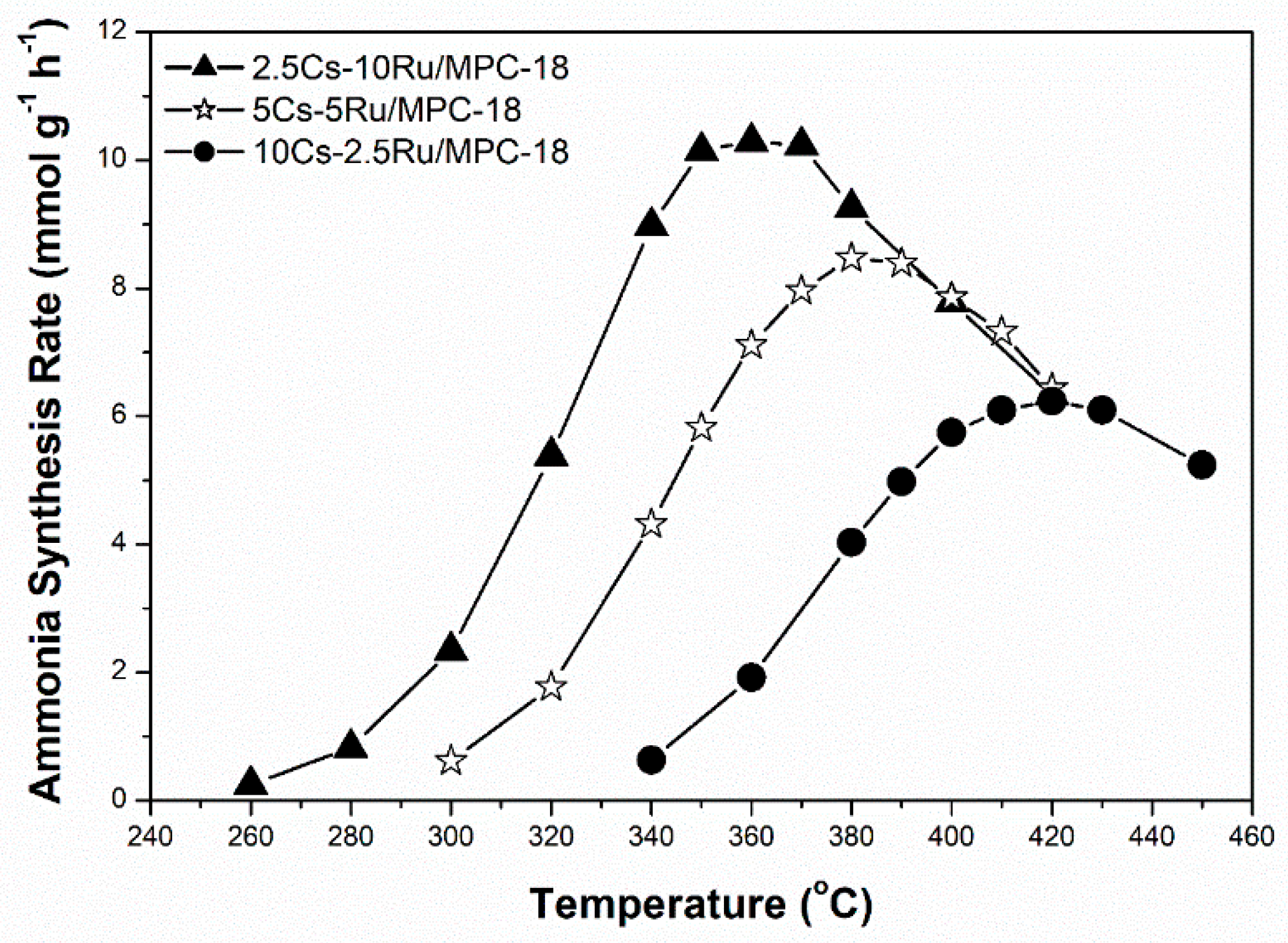
The influence of Ru loading (2.5–10 wt %) on the activity of the prepared Cs-Ru/MPC-18 catalysts with a Cs loading of 33 wt % and Cs/Ru molar ratio in the range of 2.5–10 during ammonia synthesis was studied. The reaction conditions were 280–450 °C and 0.99 MPa at 9000 h−1. Figure 7 shows that the rate of ammonia synthesis over Cs-Ru/MPC-18 catalyst is negatively related to the Ru loading whereas the reverse is true for the corresponding reaction temperature. Once again, the 2.5Cs-10Ru/MPC-18 catalyst with a Ru particle size of 2.4 nm calculated by the CO chemisorption method results in the highest activity. The other two catalysts, 5Cs-5Ru/MPC-18 and 10Cs-2.5Ru/MPC-18, with their smaller Ru particles result in relatively low rates of ammonia synthesis at relatively high temperatures, probably due to a decrease in the number of B5 sites when the Ru size is lower than 2 nm [54].
The correlation between the Ru size, the rate of ammonia synthesis and the TOF value as a function of surface Ru concentration over the prepared Cs-Ru/MPC catalysts is further discussed. The Ru sizes in the metallic state were determined by the CO chemisorption method. Figure 8a shows that the Ru sizes of the Cs-Ru/MPC catalysts are increased almost linearly from 1.3 nm to 2.5 nm by increasing the surface Ru concentration to 3.2 μmol m−2 and slightly increased to 3.7 nm at a high Ru concentration of 12 μmol m−2. Nano-sized Ru particles in the 1–4 nm region can be easily impregnated on the MPC supports in a wide range of surface Ru concentration and its sizes are highly associated with the Ru loading and the structural property of mesoporous carbon framework. However, the surface Cs concentration has no significant influence on the Ru sizes of prepared catalysts, particularly for 10Ru/MPC-18 and 2.5Cs-10Ru/MPC-18. The correlation between the rate of ammonia synthesis and the surface Ru concentration forms a volcano-shape curve for the prepared Cs-Ru/MPC catalysts (Figure 8b). The 2.5Cs-10Ru/MPC-18 catalyst with a surface Ru concentration of 3.2 μmol m−2 and a Ru size of 2.4 nm gives the highest rate of ammonia synthesis, similar to the discussion aforementioned. The rate of ammonia synthesis over the 10Ru/MPC-18 catalyst with a surface Ru concentration of 1.4 μmol m−2 and a Ru size of 2.1 nm is significantly reduced by ca. 80% and the 2.5Cs/MPC-18 catalyst is inactive in ammonia synthesis (Figure S14, ESI). It is another evidence that the co-existing Ru and CsOH impregnated on the mesoporous carbon framework give the synergetic effect in ammonia synthesis, which can be maximized by optimizing the structural parameters of surface Ru concentration (~3.2 μmol m−2), Ru size (2.4 nm) and surface Cs/Ru ratio (~1). Regarding to the other Cs-Ru/MPC catalysts, the rates of ammonia synthesis are reduced, presumably due to an improper combination of Ru size, surface Ru concentration and surface Cs/Ru ratio. Nevertheless, the TOF values over the prepared Cs-Ru/MPC catalysts remain nearly unchanged (Figure 8c), presuming that the B5 sites of nanosized Ru particles impregnated on the CsOH-containing mesoporous carbon frameworks are fully accessible. In contrast, the 2.5Cs-10Ru/AC catalyst gives a low rate of ammonia synthesis and a small TOF value because the B5 sites were lost by the sintering of nanosized Ru particles on the outer surface of CsOH-containing AC support and the molecular diffusion through the microporous carbon framework is hindered.
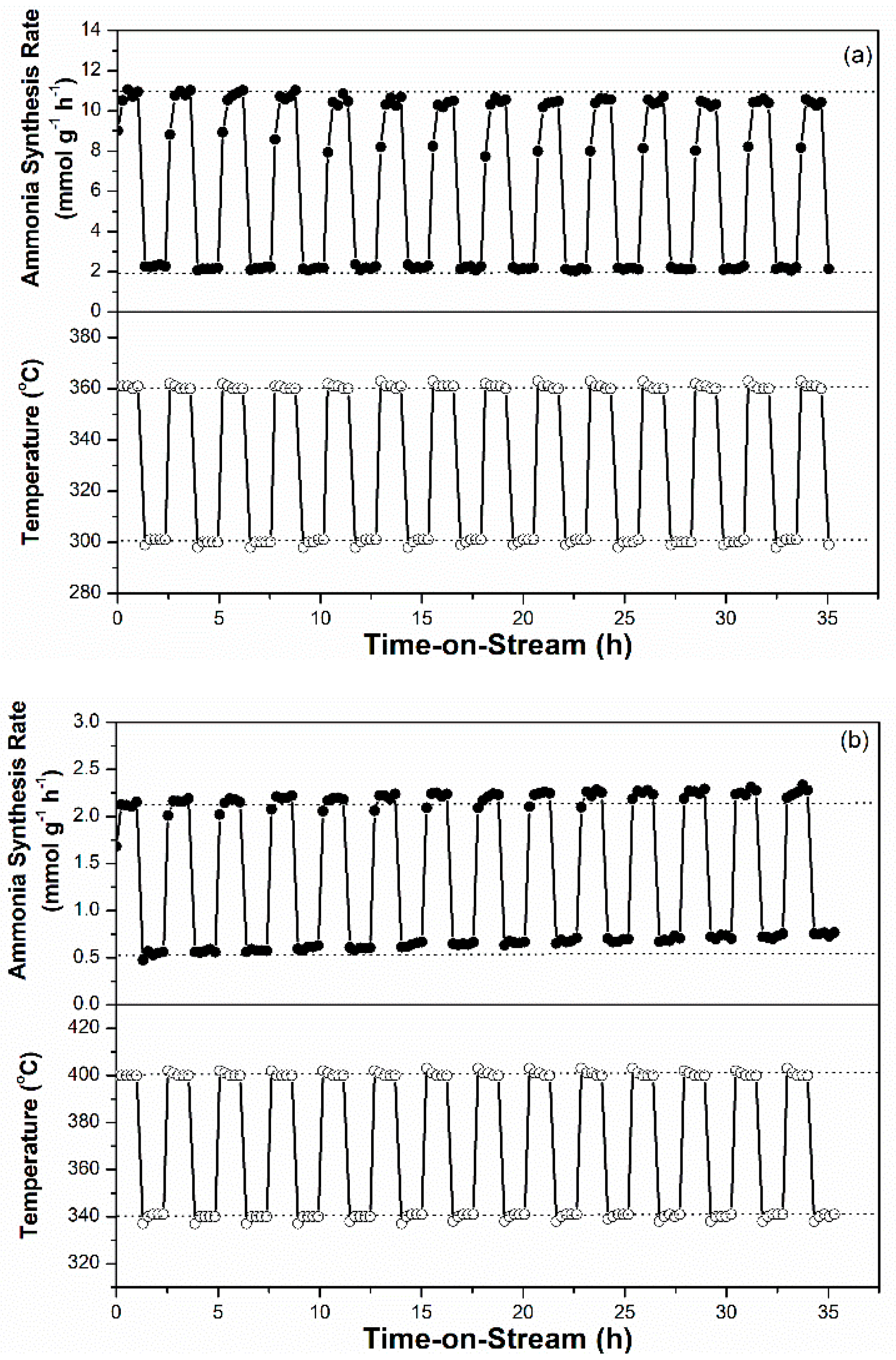
For sustainable ammonia synthesis using CO2-free hydrogen as a feedstock, Ru-based catalysts must be subjected to a short warm-up and shut-down period to cooperate with the variable production rates of renewable hydrogen from electrolysis of water through intermittently available electricity, such as wind and solar powers. The potential of the 2.5Cs-10Ru/MPC-18 catalyst for sustainable ammonia synthesis was examined across a wide SV range and its performance was compared with that of the 2.5Cs-10Ru/AC catalyst. Figure 9a shows that the rate of ammonia synthesis over the 2.5Cs-10Ru/MCP-18 catalyst was high and stable across an SV range of 3000–20,000 h−1 and reaction temperatures in the range of 320–360 °C. Figure 10 further shows that the rate of ammonia synthesis over the 2.5Cs-10Ru/MPC-18 catalyst can be quickly tuned within a short response time period (<30 min) at a temperature jump of 60 °C for around 15 cycles. It can be said that the 2.5Cs-10Ru/MPC-18 catalyst has a high potential in sustainable ammonia synthesis using CO2-free hydrogen generated from renewable energy resources. In comparison, the 2.5Cs-10Ru/AC catalyst exhibits lower activity and leads to a larger variation in ammonia synthesis when the SV values change (Figure 9b). It also suffers from a slow response time and low rate of ammonia synthesis when the reaction temperature is quickly varied. The rate of ammonia synthesis varied after each temperature jump, implying that the structure of the 2.5Cs-10Ru/AC catalyst might have changed during the reaction and it requires a long activation time for ammonia synthesis.
3. Materials and Methods
3.1. Synthesis of Mesoporous Carbon Material-Supported Cs-Ru Catalysts
Mesoporous carbon materials (a series of commercial CNovel®P(3)010 products denoted as MPC-xx) used in this study were prepared with a hard-template method at Toyo Tanso Co., Ltd., Osaka, Japan and were used as received [55]. Here, “xx” represents the annealing temperature. In other words, the notations MPC-15, MPC-18 and MPC-21 imply that their annealing temperatures were 1500, 1800 and 2100 °C, respectively. In a typical synthesis process, MPC-xx supports (1 g) were dispersed in 70 mL of an ethanol solution (50%, v/v) containing 0.31 g of nitrosylruthenium(III) nitrate (Ru(NO)(NO3)3), Ru assay = 31.4 wt %, Mitsuwa Chemicals Co., Ltd., Osaka, Japan) and slowly heated to around 70–80 °C until the solvent evaporated completely. The resulting solids were calcined at 400 °C for 3 h in N2 at a ramp rate of 5 °C min−1 to produce Ru-impregnated MPC-xx samples. Caesium carbonate (Cs2(CO3), 0.40 g, Cs = 81.6 wt %, Alfa Aesar, Lancaster, UK) was then impregnated into the Ru-impregnated MPC-xx samples by the same procedure as described above but without calcination. Note that the Ru loading was varied at 2.5–10 wt % while the Cs loading was kept constant at 33 wt % in the MPC-xx supports. The freshly prepared Cs-Ru catalysts were labelled as yCs-zRu/MPC-xx, where y and z represent the Cs/Ru molar ratio and Ru loading, respectively. For example, the notation 2.5Cs-10Ru/MPC-18 signifies that mesoporous carbon material annealed at 1800 °C (namely MPC-18) was impregnated with a Ru loading of 10 wt % at a Cs/Ru molar ratio of 2.5, corresponding to a Cs loading of 33 wt % based on the carbon content.
3.2. Synthesis of Reference Catalysts
Microporous activated carbon (denoted as AC, product code HG15-119, Osaka Gas Chemical Co., Ltd., Japan) was used as received and after mild thermal treatment at 500 °C for 3 h in an H2 environment. Ru and Cs species were impregnated into the AC support using the same procedures as described in the previous section. Thus, a 2.5Cs-10Ru/AC reference catalyst with a Ru loading of 10 wt % and a Cs/Ru molar ratio of 2.5 was prepared. Further, a 10Ru/MPC18 sample with a Ru loading of 10 wt % and a 2.5Cs/MPC18 sample with a Cs loading of 33 wt % were also prepared for comparison.
3.3. Characterization
The specific surface area and porosity of the prepared catalysts were analysed by N2 physisorption on a BELSORP-max instrument (MicrotracBEL Corp., Osaka, Japan) at 77 K. The pore size distribution (PSD) was calculated using the nonlinear density function theory (NLDFT) using a slit-pore model. The crystallinity of the prepared catalysts was determined on a Rigaku MiniFlex600 diffractometer (Tokyo, Japan) with Cu Kα radiation (λ = 0.15418 nm) and operating at 40 kV and 15 mA. The Ru particle size and size distribution were statistically analysed by high-resolution transmission electron microscopy (HRTEM) on a TOPCON EM002B instrument (Tokyo, Japan) operating at 120 kV. The microstructure of the prepared Cs-Ru catalyst was captured and mapped using a FEI Tecnai Osiris instrument (Santa Clara, CA, USA) equipped with an electron-dispersive X-ray spectroscopy (EDS) (Oregon, USA). High-angle annular dark-field scanning transmission electron microscopy-scanning transmission electron microscopy (HAADF-STEM) images were captured and analysed using the Bruker Esprit software (Massachusetts, USA). Temperature-programmed reduction (TPR) measurements of the prepared Cs-Ru catalysts were recorded on a BELCATII instrument equipped with a thermal conductive detector (TCD) and a BELMass mass spectrometer (MS) (MicrotracBEL Corp., Osaka, Japan). Freshly prepared samples were finely packed in a quartz tube and connected to the BELCATII instrument; purging was carried out with a standard gas of 5% H2 in Ar at a flow rate of 30 mL min−1 until the TCD signal was stable. The TPR-TCD and TPR-MS profiles were recorded without using a molecular sieve at the downstream in the temperature range of 50 to 800 °C at a ramp rate of 5 °C min−1. The temperature-programmed desorption of carbon dioxide (CO2-TPD) of the prepared Cs-Ru catalysts were also measured by a BELCATII instrument. Before the CO2-TPD measurement, freshly prepared samples were reduced at 450 °C for 2 h, followed by purging with an Ar flow (50 mL min−1) until the temperature was decreased to 50 °C. The reduced samples were then treated by a mixed gas of 10%CO2 in Ar (50 mL min−1) at 50 °C for 30 min, followed by purging with an Ar flow (50 mL min−1) until the TCD signal was stable. The uptakes of CO2 over the reduced samples were calculated by the CO2-TPD profiles recorded in the range of 50-800 °C at a ramp rate of 5 °C min−1. The pulse chemisorption of carbon monoxide (CO) was determined by an Ohkura Riken R6015 instrument (Saitama, Japan). For the pre-treatment, freshly prepared samples were reduced at 450 °C for 2 h, followed by purging with an Ar flow (50 mL min−1) until the TCD signal was stable. After the pre-treatment, a sequential pulse using a standard gas of 10%CO in He was injected to the reduced samples at 50 °C until no CO was adsorbed. Carbon, hydrogen and nitrogen (CHN) elemental analysis was performed on a PerkinElmer 2400II instrument (Massachusetts, USA). X-ray fluorescence (XRF) analysis was conducted on a Rigaku EDXL300 instrument (Tokyo, Japan) to monitor the Ru and Cs contents in the prepared and used Cs-Ru catalysts.
3.4. Mild Ammonia Synthesis
Typically, ammonia synthesis over the prepared Cs-Ru catalysts was carried out on a fixed-bed reactor at mild reaction conditions (280–450 °C, <1 MPa). It is specially noted that high pressure gas safety act of Japan has defined that “high pressure gas” is the pressure of the compressed gas equal to or higher than 1 MPa at 35 °C [56]. In this study, we specifically carried out mild ammonia synthesis at the reaction pressure of lower than 1 MPa using G1 grade N2 and H2 standard gases as feedstocks. The H2/N2 ratio in the feed gas was kept at 3. Typically, for ammonia synthesis, the prepared Cs-Ru catalysts sandwiched in between quartz woods were finely packed in a quartz inlet and inserted into a stainless-steel cylindrical reactor controlled by an automatic reaction test system (Taiyo system Corp., Kanagawa, Japan). Prior to the reaction, the prepared Cs-Ru catalysts were reduced on-line at 450 °C for 2 h using a H2 flow (SV = 10,000 h−1). To start ammonia synthesis, a mixed gas of hydrogen and nitrogen (H2/N2 ratio = 3) was fed and the downstream was quantitatively analysed with an online Shimadzu gas chromatograph (GC-2014) equipped with a TCD detector and a column of Thermon-3000 + KOH (2 + 2)% Sunpak-N 60/100 mesh (2.1 m length and 3.2 mm internal diameter, Shinwa Chemical Industries Ltd., Kyoto, Japan). For intermittently variable ammonia synthesis, the influence of SV (3000–20,000 h−1) was studied. Further, cycling tests of a temperature jump (ca. 60 °C) were conducted to monitor the activities of 2.5Cs-10Ru/MPC-18 and 2.5Cs-10Ru/AC for mild ammonia synthesis. The procedures for pre-reduction treatment and downstream analysis were the same as described earlier. The SV value was kept constant at 9000 h−1 during these processes. The heating and cooling rates were maintained at 5 °C min−1.
4. Conclusions
Nanostructured Cs-Ru catalysts supported on mesoporous carbon materials with different porosities and crystallinities of the graphite structure were prepared by a wet impregnation method and thermal treatment in an inert atmosphere. The studies of CO chemisorption and HRTEM-HAADF images showed that the prepared Cs-Ru/MPC catalysts contained nanosized Ru particles (around 2–3 nm) close to the Cs species, which were homogeneously impregnated inside mesoporous carbon materials of different degrees of crystallinity, which in turn were influenced by the annealing temperature. TPR studies showed that nanosized RuO2 particles were formed in the mesoporous pores of the prepared Cs-Ru/MPC catalysts and they could be reduced to metallic Ru particles at around 100–200 °C—this reduction temperature was higher than the pure RuO2 particles due to the strong interaction between Cs and Ru species. Moreover, gaseous CO2, CH4 and CO were observed at 200–500 °C, corresponding to the activation temperature region for ammonia synthesis, due to the conversion of the Cs precursor to form CsOH species and methanation of surface oxygenated species to form clean carbon surface. As a result, the metallic Ru and CsOH species close to each other as the catalytically active sites for ammonia synthesis could be confined firmly inside the mesoporous carbon framework. At higher temperatures (>600 °C), CO gas was formed due to the thermal decomposition of carbon materials; however, it could be reduced by increasing the annealing temperature of the carbon materials. For ammonia synthesis, the prepared Cs-Ru/MPC catalysts exhibited high activity under mild reaction conditions; in particular, the 2.5Cs-10Ru/MPC-18 catalyst with a proper size of metallic Ru nanoparticles (2.4 nm), which were co-impregnated with CsOH species inside the mesoporous carbon framework and surface Ru and Cs concentrations of ca. 3–4 μmol m−2 corresponding to a surface Cs/Ru ratio of ca. 1 exhibited excellent activity at lower temperatures (7.3–10.2 mmol g−1 h−1 at 360–370 °C). Ru particle size and size distribution in the fresh and used 2.5Cs-10Ru/MPC-18 catalysts were similar, whereas those of the microporous catalyst (2.5Cs-10Ru/AC) changed significantly, resulting in a low activity and stability for ammonia synthesis due to serious deactivation by Ru-particle sintering. Moreover, the 2.5Cs-10Ru/MPC-18 catalyst with its mesoporous carbon framework and small Ru size and narrow size distribution showed high responsibility and durability in intermittently variable ammonia synthesis in a wide SV region and in cycling tests with a large temperature variation. Therefore, we are demonstrating, for the first time, that sustainable ammonia synthesis can be carried out by the nanostructured Cs-Ru catalysts under mild conditions using CO2-free hydrogen derived from renewable energy with intermittent operation in Fukushima Renewable Energy Institute (FREA) of AIST, Japan and the results will be reported in the near future.
Supplementary Materials
The following are available online at https://www.mdpi.com/2073-4344/9/5/406/s1, The TPR analysis, electronic microscopy and supplementary of catalytic tests of prepared catalysts, in comparison to those of reference catalysts. Table S1: TPR-MS data of the prepared Cs-Ru catalysts, Figure S1: HRTEM images of carbon supports (a) AC, (b) MPC-15, (c) MPC-18 and (d) MPC-21, Figure S2: HAADF-STEM images of 2.5Cs-10Ru/MPC-15 catalysts. (a) Fresh and (b) used samples, Figure S3: HAADF-STEM images of 2.5Cs-10Ru/MPC-18 catalysts. (a) Fresh and (b) used samples, Figure S4: HAADF-STEM images of 2.5Cs-10Ru/MPC-21 catalysts. (a) Fresh and (b) used samples, Figure S5: HAADF-STEM images of 2.5Cs-10Ru/AC catalysts. (a) Fresh and (b) used samples, Figure S6: TPR-TCD and TPR-MS profiles of RuO2, Figure S7: TPR-TCD and TPR-MS profiles of MPC-18, Figure S8: TPR-TCD and TPR-MS profiles of 10Ru/MPC-18 obtained by the dispersion of MPC-18 (1 g) in 70 mL of ethanol (50%, v/v) containing 0.31 g of nitrosylruthenium(III) nitrate (Ru(NO)(NO3)3) and slowly heating to around 70–80 °C until the solvent completely evaporated. This was followed by calcination at 400 °C for 3 h in N2 at a ramp rate of 5 °C min−1, Figure S9: TPR-TCD and TPR-MS profiles of 2.5Cs/MPC-18 obtained by the dispersion of MPC-18 (1 g) in 70 mL of ethanol (50%, v/v) containing a 0.40 g of caesium carbonate (Cs2(CO3) and slowly heating to around 70–80 °C until the solvent completely evaporated, Figure S10: TPR-MS profiles of freshly prepared catalysts (a) 2.5Cs-10Ru/AC, (b) 2.5Cs-10Ru/MPC-15, (c) 2.5Cs-10Ru/MPC-18 and (d) 2.5Cs-10Ru/MPC-21, Figure S11: TPR-MS profiles (m/z = 18) of freshly prepared Cs-Ru catalysts, Figure S12: HRTEM images and Ru particle size distributions of the used catalysts. (a) 2.5Cs-10Ru/MPC-AC, (b) 2.5Cs-10Ru/MPC-15, (c) 2.5Cs-10Ru/MPC-18 and (d) 2.5Cs-10Ru/MPC-21, Figure S13: Wide-angle XRD patterns of used catalysts. (a) 2.5Cs-10Ru/AC, (b) 2.5Cs-10Ru/MPC-15, 2.5Cs-10Ru/MPC-18 and (d) 2.5Cs-10Ru/MPC-21, Figure S14: Rate of ammonia synthesis as a function of reaction temperature over the 10Ru/MPC-18 and 2.5Cs/MPC-18 catalysts at an SV value of 9000 h−1.
Author Contributions
M.N. designed and performed the experiments including the preparation and characterization of the catalysts and their catalyst activity tests and wrote the original paper; S.-Y.C. conceived of the characterization and catalytic tests of the prepared catalysts as well as reviewed and edited the paper; H.T. proposed and supervised the project. All the authors discussed and commented on the paper.
Funding
This research was funded by Japan Science and Technology Agency (JST), the Council for Science, Technology and Innovation (CSTI), the Cross-ministerial Strategic Innovation Promotion Program (SIP) and the Energy Carriers program.
Acknowledgments
The authors acknowledge financial support from the Council for Science, Technology and Innovation (CSTI), the Cross-ministerial Strategic Innovation Promotion Program (SIP) and the Energy Carriers program funded by Japan Science and Technology Agency (JST). Furthermore, the authors would like to express their gratitude to Mr. Akira Takatsuki of RIEF, AIST, for assisting with the HRTEM and HAADF-STEM measurements, Dr. Koji Kuramoto of RIEF, AIST, for assistance with XRD measurements, Dr. Takehisa Mochizuki of RIEF, AIST, for his help constructing the CO chemisorption instrument and Mr. Kiyoaki Imoto of RIEF, AIST, for his help conducting mild ammonia synthesis. Special thanks to Editage (https://www.editage.jp/) for English language editing.
Conflicts of Interest
The authors declare no conflict of interest.
References
- U.S. Energy Information Administration (EIA). International Energy Outlook 2017. Available online: https://www.eia.gov/outlooks/ieo/pdf/0484(2017).pdf (accessed on 11 July 2018).
- United Nations Framework Convention on Climate Change (UNFCCC). Paris agreement. Available online: https://unfccc.int/sites/default/files/english_paris_agreement.pdf (accessed on 8 April 2019).
- Ministry of the Environment, Outline of Long-term Low-carbon Vision. Available online: http://www.env.go.jp/press/103822/713.pdf (accessed on 11 July 2018).
- Ministry of Economy, Trade and Industry, Basic Hydrogen Strategy. Available online: http://www.meti.go.jp/english/press/2017/pdf/1226_003a.pdf (accessed on 6 August 2018).
- Gandía, L.M.; Oroz, R.; Ursúa, A.; Sanchis, P.; Diéguez, P.M. Renewable hydrogen production: performance of an alkaline water electrolyzer working under emulated wind conditions. Energy Fuels 2007, 21, 1699–1706. [Google Scholar] [CrossRef]
- Felice, L.D.; Courson, C.; Jand, N.; Gallucci, K.; Foscolo, P.U.; Kiennemann, A. Catalytic biomass gasification: Simultaneous hydrocarbons steam reforming and CO2 capture in a fluidised bed reactor. Chem. Eng. J. 2009, 154, 375–383. [Google Scholar] [CrossRef]
- Mukherjee, S.; Devaguptapu, S.V.; Sviripa, A.; Lund, C.R.F.; Wu, G. Low-temperature ammonia decomposition catalysts for hydrogen generation. Appl. Catal. B Environ. 2018, 226, 162–181. [Google Scholar] [CrossRef]
- Ju, X.; Liu, L.; Yu, P.; Guo, J.; Zhang, X.; He, T.; Wu, G.; Chen, P. Mesoporous Ru/MgO prepared by a deposition-precipitation method as highly active catalyst for producing COx-free hydrogen from ammonia decomposition. Appl. Catal. B Environ. 2017, 211, 167–175. [Google Scholar] [CrossRef]
- Yin, S.F.; Xu, B.Q.; Ng, C.F.; Au, C.T. Nano Ru/CNTs: a highly active and stable catalyst for the generation of COx-free hydrogen in ammonia decomposition. Appl. Catal. B Environ. 2004, 48, 237–241. [Google Scholar] [CrossRef]
- Wang, S.J.; Yin, S.F.; Li, L.; Xu, B.Q.; Ng, C.F.; Au, C.T. Investigation on modification of Ru/CNTs catalyst for the generation of COx-free hydrogen from ammonia. Appl. Catal. B Environ. 2004, 52, 287–299. [Google Scholar] [CrossRef]
- US Geological Survey, Nitrogen (Fixed)–Ammonia. Available online: https://minerals.usgs.gov/minerals/pubs/commodity/nitrogen/mcs-2019-nitro.pdf (accessed on 1 February 2019).
- Smil, V. Detonator of the population explosion. Nature 1999, 400, 415. [Google Scholar] [CrossRef]
- Schrock, R.R. Reduction of dinitrogen. Proc. Natl. Acad. Sci. USA 2006, 103, 17087. [Google Scholar] [CrossRef] [PubMed]
- Farla, J.C.M.; Hendriks, C.A.; Blok, K. Carbon dioxide recovery from industrial processes. Energy Convers. Manag. 1995, 36, 827–830. [Google Scholar] [CrossRef]
- Ozaki, A.; Aika, K.; Hori, H. A new catalyst system for ammonia synthesis. Bull. Chem. Soc. Jpn. 1971, 44, 3216. [Google Scholar] [CrossRef]
- Aika, K.; Hori, H.; Ozaki, A. Activation of nitrogen by alkali metal promoted transition metal I. Ammonia synthesis over ruthenium promoted by alkali metal. J. Catal. 1972, 27, 424–431. [Google Scholar] [CrossRef]
- Truszkiewicz, E.; Raróg-Pilecka, W.; Schmidt-Szałowski, K.; Jodzis, S.; Wilczkowska, E.; Łomot, D.; Kaszkur, Z.; Karpiński, Z.; Kowalczyk, Z. Barium-promoted Ru/carbon catalyst for ammonia synthesis: State of the system when operating. J. Catal. 2009, 286, 181–190. [Google Scholar] [CrossRef]
- Rossetti, I.; Mangiarini, F.; Forni, L. Promoters state and catalyst activation during ammonia synthesis over Ru/C. Appl. Catal. A Gen. 2007, 323, 219–225. [Google Scholar] [CrossRef] [Green Version]
- Lin, B.; Qi, Y.; Guo, Y.; Lin, J.; Ni, J. Effect of potassium precursors on the thermal stability of K-promoted Ru/carbon catalysts for ammonia synthesis. Catal. Sci. Technol. 2015, 5, 2829–2838. [Google Scholar] [CrossRef]
- Fernández, C.; Sassoye, C.; Debecker, D.P.; Sanchez, C.; Ruiz, P. Effect of the size and distribution of supported Ru nanoparticles on their activity in ammonia synthesis under mild reaction conditions. Appl. Catal. A Gen. 2014, 474, 194–202. [Google Scholar]
- Hansen, T.W.; Hansen, P.L.; Dahl, S.; Jacobsen, C.J.H. Support effect and active sites on promoted ruthenium catalysts for ammonia synthesis. Catal. Lett. 2002, 84, 7–12. [Google Scholar] [CrossRef]
- Brown, D.E.; Edmonds, T.; Joyner, R.W.; McCarroll, J.J.; Tennison, S.R. The genesis and development of the commercial BP doubly promoted catalyst for ammonia synthesis. Catal. Lett. 2014, 144, 545–552. [Google Scholar] [CrossRef]
- Sato, K.; Imamura, K.; Kawano, Y.; Miyahara, S.; Yamamoto, T.; Matsumura, S.; Nagaoka, K. A low-crystalline ruthenium nano-layer supported on praseodymium oxide as an active catalyst for ammonia synthesis. Chem. Sci. 2017, 8, 674–679. [Google Scholar] [CrossRef]
- Ogura, Y.; Sato, K.; Miyahara, S.; Kawano, Y.; Toriyama, T.; Yamamoto, T.; Matsumura, S.; Hosokawa, S.; Nagaoka, K. Efficient ammonia synthesis over a Ru/La0.5Ce0.5O1.75 catalyst pre-reduced at high temperature. Chem. Sci. 2018, 9, 2230–2237. [Google Scholar] [CrossRef]
- Kitano, M.; Kanbara, S.; Inoue, Y.; Kuganathan, N.; Sushko, P.V.; Yokoyama, T.; Hara, M.; Hosono, H. Electride support boosts nitrogen dissociation over ruthenium catalyst and shifts the bottleneck in ammonia synthesis. Nat. Commun. 2015, 6, 6731. [Google Scholar] [CrossRef] [PubMed] [Green Version]
- Kitano, M.; Inoue, Y.; Sasase, M.; Kishida, K.; Kobayashi, Y.; Nishiyama, K.; Tada, T.; Kawamura, S.; Yokoyama, T.; Hara, M.; et al. Self-organized ruthenium–barium core–shell nanoparticles on a mesoporous calcium amide matrix for efficient low-temperature ammonia synthesis. Angew. Chem. Int. Ed. 2018, 57, 2648–2652. [Google Scholar] [CrossRef]
- Mao, C.; Yu, L.; Li, J.; Zhao, J.; Zhang, L. Energy-confined solar thermal ammonia synthesis with K/Ru/TiO2−xHx. Appl. Catal. B Environ. 2018, 224, 612–620. [Google Scholar] [CrossRef]
- Raróg-Pilecka, W.; Miśkiewicz, E.; Szmigiel, D.; Kowalczyk, Z. Structure sensitivity of ammonia synthesis over promoted ruthenium catalysts supported on graphitised carbon. J. Catal. 2005, 231, 11–19. [Google Scholar] [CrossRef]
- Raróg-Pilecka, W.; Miśkiewicz, E.; Jodzis, S.; Petryk, J.; Łomot, D.; Kaszkur, Z.; Karpiński, Z.; Kowalczyk, Z. Carbon-supported ruthenium catalysts for NH3 synthesis doped with caesium nitrate: Activation process, working state of Cs–Ru/C. J. Catal. 2006, 239, 313–325. [Google Scholar] [CrossRef]
- Kowalczyk, Z.; Jodzis, S.; Raróg, W.; Zielinski, J.; Pielaszek, J.; Presz, A. Carbon-supported ruthenium catalyst for the synthesis of ammonia. The effect of the carbon support and barium promoter on the performance. Appl. Catal. A Gen. 1999, 184, 95–102. [Google Scholar] [CrossRef]
- Rossetti, I.; Pernicone, N.; Forni, L. Graphitised carbon as support for Ru/C ammonia synthesis catalyst. Catal. Today 2005, 102–103, 219–224. [Google Scholar] [CrossRef]
- Zeng, H.S.; Inazu, K.; Aika, K. The working state of the barium promoter in ammonia synthesis over an active-carbon-supported ruthenium catalyst using barium nitrate as the promoter precursor. J. Catal. 2002, 211, 33–41. [Google Scholar] [CrossRef]
- Nishi, M.; Chen, S.Y.; Takagi, H. A mesoporous carbon-supported and Cs-promoted Ru catalyst with enhanced activity and stability for sustainable ammonia synthesis. ChemCatChem 2018, 10, 3411–3414. [Google Scholar] [CrossRef]
- Kresge, C.T.; Leonowicz, M.E.; Roth, W.J.; Vartuli, J.C.; Beck, J.S. Orderd mesoporous molecular sieves synthesized by a liquid-crystal template mechanism. Nature 1992, 359, 710–712. [Google Scholar] [CrossRef]
- Beck, J.S.; Vartuli, J.C.; Roth, W.J.; Leonowicz, M.E.; Kresge, C.T.; Schmitt, K.D.; Chu, C.T.W.; Olson, D.H.; Sheppard, E.W.; McCullen, S.B.; Higgins, J.B.; Schlenker, J.L. A new family of mesoporous molecular sieves prepared with liquid crystal templates. J. Am. Chem. Soc. 1992, 114, 10834–10843. [Google Scholar] [CrossRef]
- Zhao, D.Y.; Feng, J.L.; Huo, Q.S.; Melosh, N.; Fredrickson, G.H.; Chmelka, B.F.; Stucky, G.D. Triblock copolymer syntheses of mesoporous silica with periodic 50 to 300 angstrom pores. Science 1998, 279, 548–552. [Google Scholar] [CrossRef] [PubMed]
- Zhao, D.Y.; Huo, Q.S.; Feng, J.L.; Chmelka, B.F.; Stucky, G.D. Nonionic triblock and star diblock copolymer and oligomeric surfactant syntheses of highly ordered, hydrothermally stable, mesoporous silica structures. J. Am. Chem. Soc. 1998, 120, 6024–6036. [Google Scholar] [CrossRef]
- Fukuoka, A.; Kimura, J.; Oshio, T.; Sakamoto, Y.; Ichikawa, M. Preferential oxidation of carbon monoxide catalysed by platinum nanoparticles in mesoporous silica. J. Am. Chem. Soc. 2007, 129, 10120–10125. [Google Scholar] [CrossRef] [PubMed]
- Olkhovyk, O.; Jaroniec, M. Periodic mesoporous organosilica with large heterocyclic bridging groups. J. Am. Chem. Soc. 2004, 127, 60–61. [Google Scholar] [CrossRef] [PubMed]
- Inagaki, S.; Guan, S.; Fukushima, Y.; Ohsuna, T.; Terasaki, O. Novel mesoporous materials with a uniform distribution of organic groups and inorganic oxide in their frameworks. J. Am. Chem. Soc. 1999, 121, 9611–9614. [Google Scholar] [CrossRef]
- Liang, C.D.; Dai, S. Synthesis of mesoporous carbon materials via enhanced hydrogen-bonding interaction. J. Am. Chem. Soc. 2006, 128, 5216–5317. [Google Scholar] [CrossRef]
- Lee, J.S.; Joo, S.H.; Ryoo, R. Synthesis of mesoporous silicas of controlled pore wall thickness and their replication to ordered nanoporous carbons with various pore diameters. J. Am. Chem. Soc. 2002, 124, 1156–1157. [Google Scholar] [CrossRef] [PubMed]
- Zhang, F.Q.; Meng, Y.; Gu, D.; Yan, Y.; Yu, C.Z.; Tu, B.; Zhao, D.Y. A facile aqueous route to synthesize highly ordered mesoporous polymers and carbon frameworks with Ia(3)over-bard bicontinuous cubic structure. J. Am. Chem. Soc. 2005, 127, 13508–13509. [Google Scholar] [CrossRef]
- Kasahara, N.; Shiraishi, S.; Oya, A. Heterogeneous graphitization of thin carbon fiber derived from phenol-formaldehyde resin. Carbon 2003, 41, 1654–1656. [Google Scholar] [CrossRef]
- Eslava, J.L.; Iglesias-Juez, A.; Agostini, G.; Fernández-García, M.; Guerrero-Ruiz, A.; Rodríguez-Ramos, I. Time-resolved XAS investigation of the local environment and evolution of oxidation states of a Fischer–Tropsch Ru–Cs/C catalyst. ACS Catal. 2016, 6, 1437–1445. [Google Scholar] [CrossRef]
- Rossetti, I.; Forni, L. Effect of Ru loading and of Ru precursor in Ru/C catalysts for ammonia synthesis. Appl. Catal. A Gen. 2005, 282, 315–320. [Google Scholar] [CrossRef] [Green Version]
- Hill, A.K.; Torrente-Murciano, L. Low temperature H2 production from ammonia using ruthenium-based catalysts: Synergetic effect of promoter and support. Appl. Catal. B Environ. 2015, 172–173, 129–135. [Google Scholar] [CrossRef]
- Lin, B.; Guo, Y.; Lin, J.; Ni, J.; Lin, J.; Jiang, L.; Wang, Y. Deactivation study of carbon-supported ruthenium catalyst with potassium promoter. Appl. Catal. A Gen. 2017, 541, 1–7. [Google Scholar] [CrossRef]
- Addoun, A.; Dentzer, J.; Ehrburger, P. Porosity of carbons obtained by chemical activation: effect of the nature of the alkaline carbonates. Carbon 2002, 40, 1140–1143. [Google Scholar] [CrossRef]
- Li, C.; Shao, Z.; Pang, M.; Williams, C.T.; Zhang, X.; Liang, C. Carbon nanotubes supported mono- and bimetallic Pt and Ru catalysts for selective hydrogenation of phenylacetylene. Ind. Eng. Chem. Res. 2012, 51, 4934–4941. [Google Scholar] [CrossRef]
- Li, Z.; Liang, C.; Feng, Z.; Ying, P.; Wang, D.; Li, C. Ammonia synthesis on graphitic-nanofilament supported Ru catalysts. J. Mol. Catal. A Chem. 2004, 211, 103–109. [Google Scholar] [CrossRef] [Green Version]
- Jacobsen, C.J.H.; Dahl, S.; Hansen, P.L.; Törnqvist, E.; Jensen, L.; Topsøe, H.; Prip, D.V.; Møenshaug, P.B.; Chorkendorff, I. Structure sensitivity of supported ruthenium catalysts for ammonia synthesis. J. Mol. Catal. A Chem. 2000, 163, 19–26. [Google Scholar] [CrossRef]
- Aika, K. Role of alkali promoter in ammonia synthesis over ruthenium catalysts—Effect on reaction mechanism. Catal. Today 2017, 286, 14–20. [Google Scholar] [CrossRef]
- Liang, C.; Wei, Z.; Xin, Q.; Li, C. Ammonia synthesis over Ru/C catalysts with different carbon supports promoted by barium and potassium compounds. Appl. Catal. A Gen. 2001, 208, 193–201. [Google Scholar] [CrossRef] [Green Version]
- Morishita, T.; Tsumura, T.; Toyoda, M.; Przepiorski, J.; Morawski, A.W.; Konno, H.; Inagaki, M. A review of the control of pore structure in MgO-templated nanoporous carbons. Carbon 2010, 48, 2707. [Google Scholar] [CrossRef]
- Overview of the High Pressure Gas Safety Act. Available online: https://www.khk.or.jp/Portals/0/resources/english/dl/overview_hpg_act.pdf (accessed on 1 October 2016).
Figure 1.
Wide-angle X-ray diffraction (XRD) patterns of (A) carbon materials—(a) AC, (b) MPC-15, (c) MPC-18 and (d) MPC-21 and (B) the prepared Cs-Ru catalysts—(e) 2.5Cs-10Ru/AC, (f) 2.5Cs-10Ru/MPC-15, (g) 10Cs-2.5Ru/MPC-18, (h) 5Cs-5Ru/MPC-18, (i) 2.5Cs-10Ru/MPC-18 and (j) 2.5Cs-10Ru/MPC-21. The “asterisk” peaks are associated with the carbon materials. The peaks of samples (d) and (j) are enlarged and inserted in Figure 1A,B, respectively.

Figure 2.
N2 adsorption-desorption isotherms of (A) carbon materials—(a) AC, (b) MPC-15, (c) MPC-18 and (d) MPC-21 and (B) the prepared Cs-Ru catalysts—(e) 2.5Cs-10Ru/AC, (f) 2.5Cs-10Ru/MPC-15, (g) 10Cs-2.5Ru/MPC-18, (h) 5Cs-5Ru/MPC-18, (i) 2.5Cs-10Ru/MPC-18 and (j) 2.5Cs-10Ru/MPC-21.
Figure 2.
N2 adsorption-desorption isotherms of (A) carbon materials—(a) AC, (b) MPC-15, (c) MPC-18 and (d) MPC-21 and (B) the prepared Cs-Ru catalysts—(e) 2.5Cs-10Ru/AC, (f) 2.5Cs-10Ru/MPC-15, (g) 10Cs-2.5Ru/MPC-18, (h) 5Cs-5Ru/MPC-18, (i) 2.5Cs-10Ru/MPC-18 and (j) 2.5Cs-10Ru/MPC-21.

Figure 3.
HRTEM images and Ru particle size distributions of freshly prepared catalysts. (a) 2.5Cs-10Ru/AC, (b) 2.5Cs-10Ru/MPC-15, (c) 2.5Cs-10Ru/MPC-18 and (d) 2.5Cs-10Ru/MPC-21.
Figure 3.
HRTEM images and Ru particle size distributions of freshly prepared catalysts. (a) 2.5Cs-10Ru/AC, (b) 2.5Cs-10Ru/MPC-15, (c) 2.5Cs-10Ru/MPC-18 and (d) 2.5Cs-10Ru/MPC-21.

Figure 4.
(A) Temperature-programmed reduction equipped with a thermal conductivity detector (TPR-TCD) and (B–F) temperature-programmed reduction equipped with a mass spectrometer (TPR-MS) profiles of freshly prepared catalysts. (a) 2.5Cs-10Ru/AC, (b) 2.5Cs-10Ru/MPC-15, (c) 2.5Cs-10Ru/MPC-18 and (d) 2.5Cs-10Ru/MPC-21.
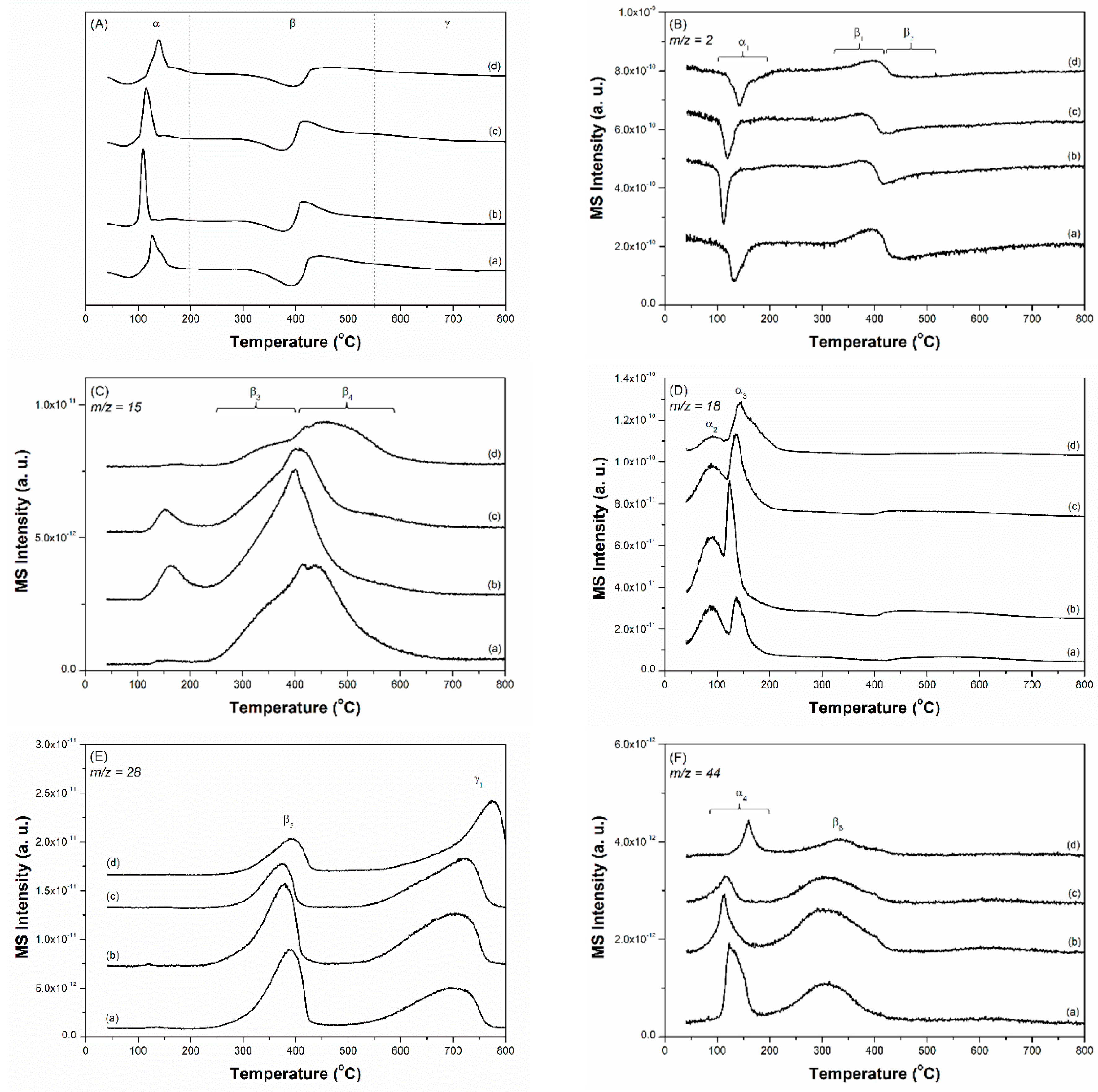
Figure 5.
(A) TPR-TCD profile, (B) TPR-MS profile recorded by a m/z ratio of 13, and (C) TPR-MS profile recorded by a m/z ratio of 17 for the ammonia synthesis over freshly prepared catalysts. (a) 2.5Cs-10Ru/AC, (b) 2.5Cs-10Ru/MPC-15, (c) 2.5Cs-10Ru/MPC-18, (d) 2.5Cs-10Ru/MPC-21, (e) 10Ru/MPC-18 and (f) 2.5Cs/MPC-18.

Figure 6.
Rate of ammonia synthesis as a function of reaction temperature over the prepared Cs-Ru catalysts at an SV value of 9000 h−1.
Figure 6.
Rate of ammonia synthesis as a function of reaction temperature over the prepared Cs-Ru catalysts at an SV value of 9000 h−1.
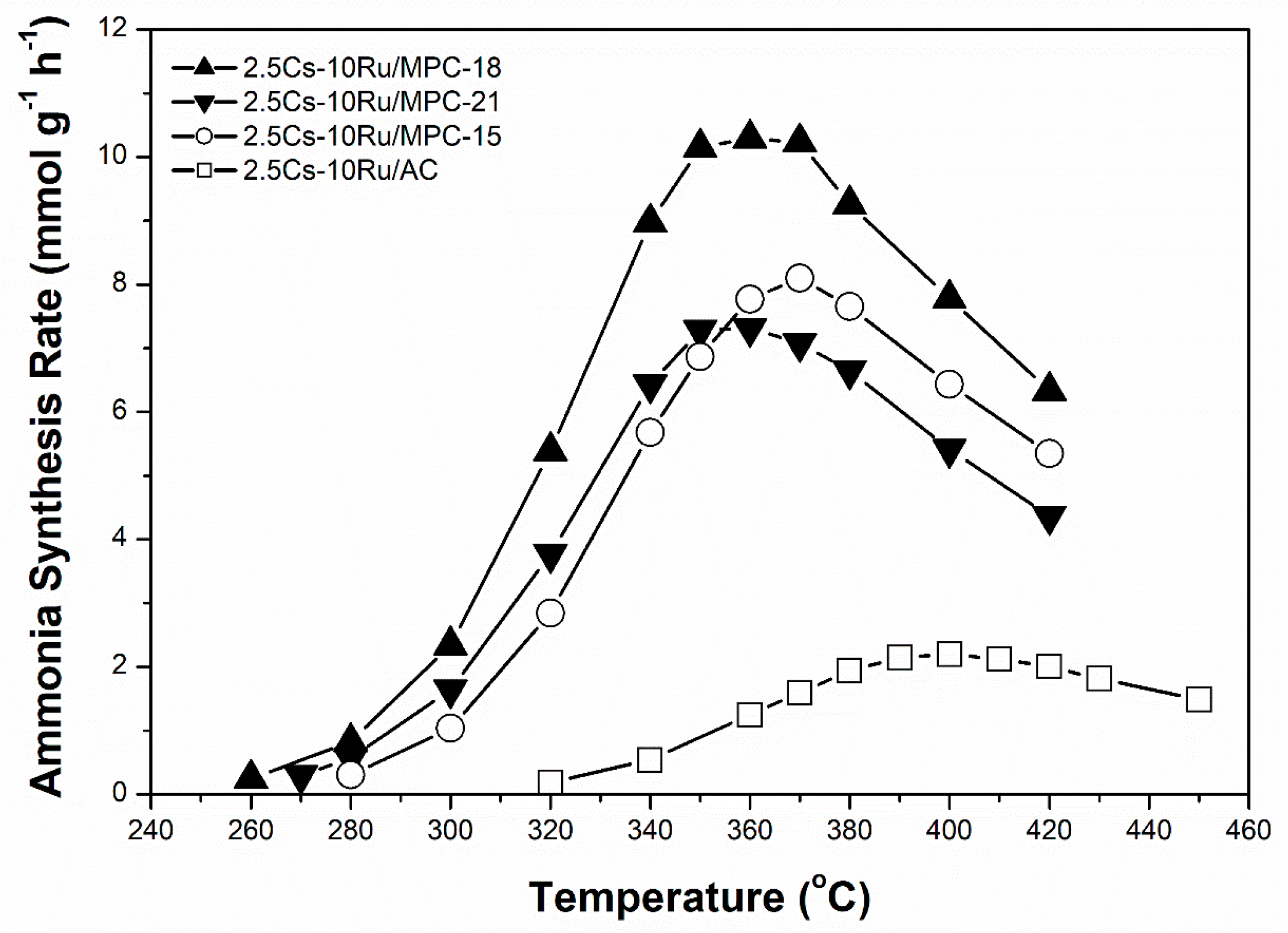
Figure 7.
Rate of ammonia synthesis as a function of Ru loading over Cs-Ru/MPC-18 catalysts.

Figure 8.
(a) The Ru size; (b) ammonia synthesis rate; and (c) TOF as a function of surface Ru concentration over the prepared Cs-Ru/MPC catalysts, in comparison to those of 10Ru/MPC-18 and 2.5Cs-10Ru/AC catalysts.
Figure 8.
(a) The Ru size; (b) ammonia synthesis rate; and (c) TOF as a function of surface Ru concentration over the prepared Cs-Ru/MPC catalysts, in comparison to those of 10Ru/MPC-18 and 2.5Cs-10Ru/AC catalysts.
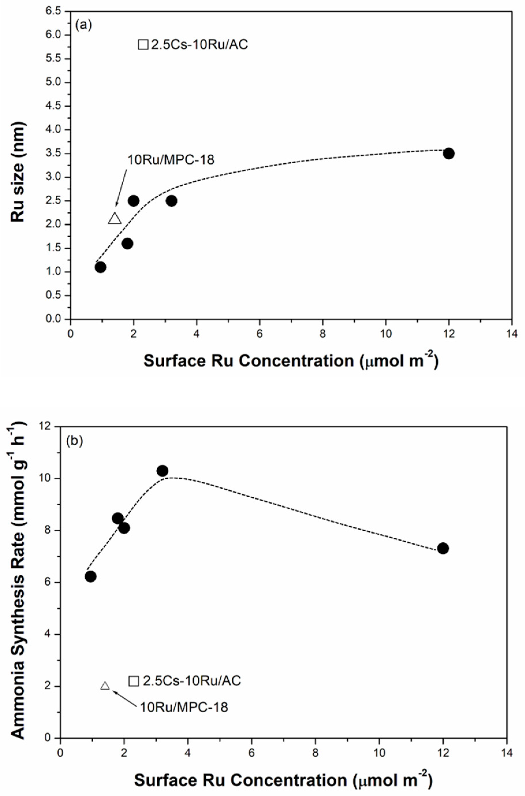
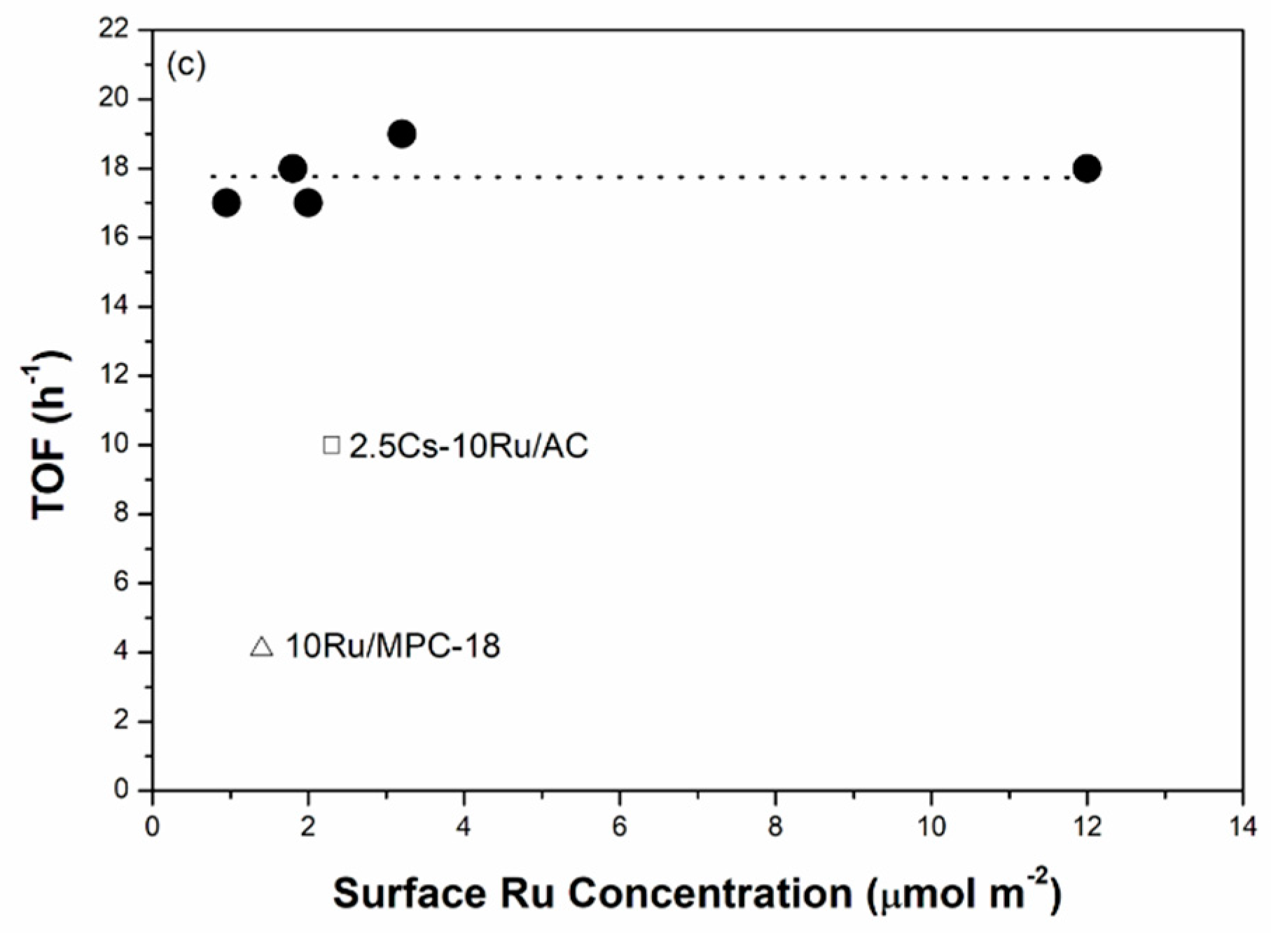
Figure 9.
Rate of ammonia synthesis as a function of space velocity (SV) over the prepared Cs-Ru catalysts: (a) 2.5Cs-10Ru/MPC-18 and (b) 2.5Cs-10Ru/AC.
Figure 9.
Rate of ammonia synthesis as a function of space velocity (SV) over the prepared Cs-Ru catalysts: (a) 2.5Cs-10Ru/MPC-18 and (b) 2.5Cs-10Ru/AC.
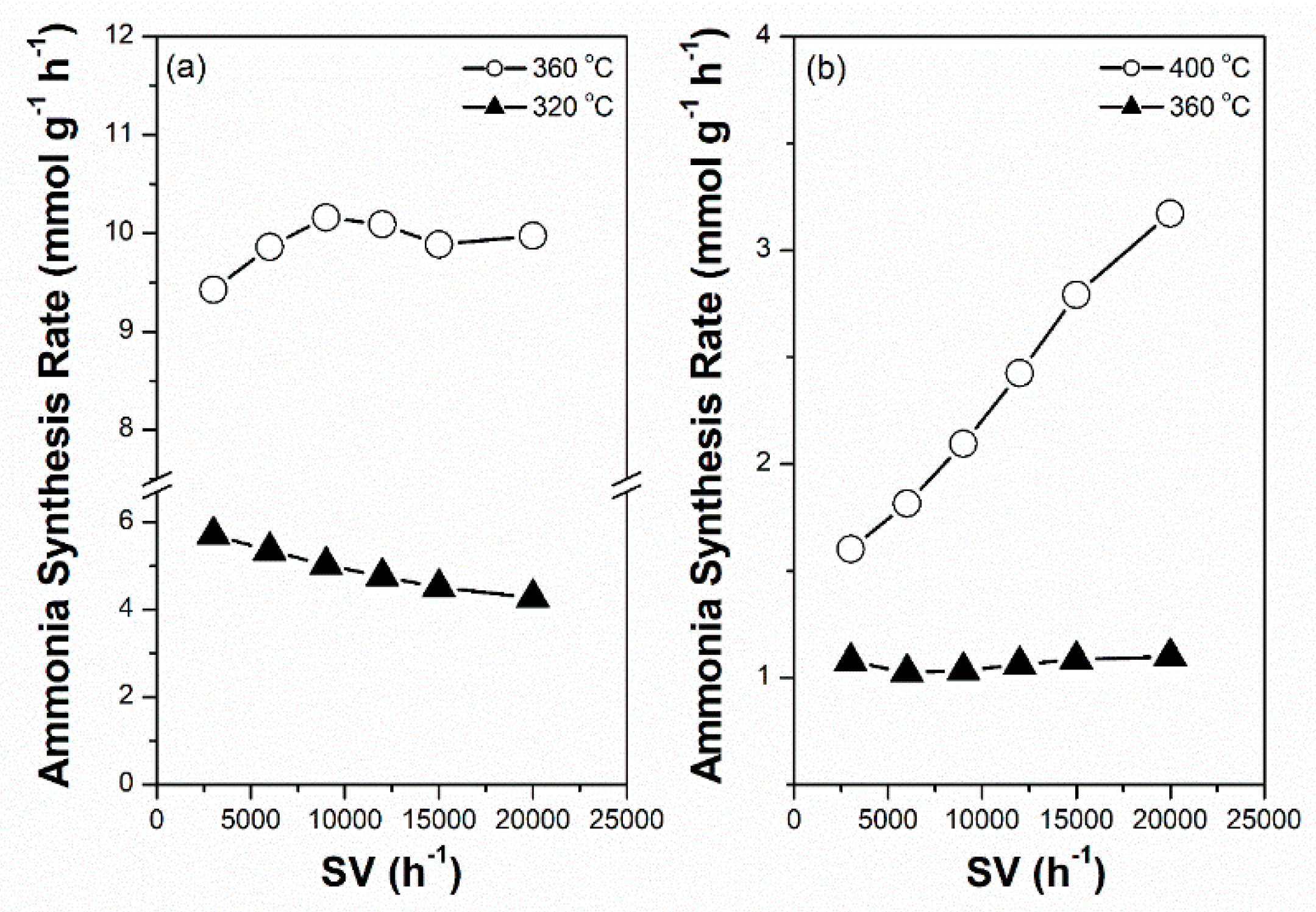
Figure 10.
Intermittently variable ammonia synthesis over the prepared Ru-Cs catalysts: (a) 2.5Cs-10Ru/MPC-18 and (b) 2.5Cs-10Ru/AC.
Figure 10.
Intermittently variable ammonia synthesis over the prepared Ru-Cs catalysts: (a) 2.5Cs-10Ru/MPC-18 and (b) 2.5Cs-10Ru/AC.

Table 1.
Structural properties of carbon materials and the as-prepared Cs-Ru catalysts.
| Samples | Cs/Ru Molar Ratio | Ru Loading (wt %) | SBET (m2 g−1) | VTotal (cm3 g−1) | VMicro. (cm3 g−1) 3 | VMeso. (cm3 g−1) 4 | Pore Size (nm) | ||
|---|---|---|---|---|---|---|---|---|---|
| (Expected) 1 | (Solid) 2 | (Expected) 1 | (Solid) 2 | ||||||
| AC | - | - | - | - | 1260 | 0.62 | 0.51 | 0.11 | 1.6 |
| MPC-15 | - | - | - | - | 1180 | 2.94 | 0.55 | 2.39 | 5.8 |
| MPC-18 | - | - | - | - | 930 | 2.29 | 0.37 | 1.92 | 5.1 |
| MPC-21 | - | - | - | - | 270 | 1.28 | 0.11 | 1.17 | 6.8 |
| 2.5Cs-10Ru/AC | 2.5 | 1.3 | 10 | 13.4 | 580 | 0.30 | 0.24 | 0.06 | 1.6 |
| 2.5Cs-10Ru/MPC/15 | 2.5 | 1.1 | 10 | 13.7 | 680 | 1.81 | 0.27 | 1.54 | 5.8 |
| 2.5Cs-10Ru/MPC-18 | 2.5 | 1.1 | 10 | 13.8 | 430 | 1.33 | 0.17 | 1.16 | 5.8 |
| 5Cs-5Ru/MPC-18 | 5.0 | 2.1 | 5.0 | 8.1 | 440 | 1.40 | 0.18 | 1.22 | 5.8 |
| 10Cs-2.5Ru/MPC-18 | 10 | 3.7 | 2.5 | 4.8 | 500 | 1.52 | 0.20 | 1.32 | 5.8 |
| 2.5Cs/MPC-18 | - | - 5 | - | - | 580 | 1.71 | 0.23 | 1.48 | 5.8 |
| 10Ru/MPC-18 | - | - | 10 | 11.3 | 800 | 1.84 | 0.32 | 1.52 | 5.1 |
| 2.5Cs-10Ru/MPC-21 | 2.5 | 1.1 | 10 | 13.4 | 110 | 0.58 | 0.04 | 0.54 | 7.3 |
1 Theoretical Cs/Ru molar ratios and Ru loadings, which were based on the carbon content. 2 The Cs and Ru loadings in solids were measured by EA and XRF methods. 3 Microporous pore volume (VMicro) was calculated using the Dubinin-Astakhov (DA) plot and the αs-plot method. 4 Mesoporous pore volume (VMeso) was calculated as VTotal − VMicro. 5 The Cs loading was 32.4 wt % according to the EA and XRF method.
Table 2.
HRTEM image and gas chemisorption studied on the Ru and Cs species of the prepared Cs-Ru catalysts and their catalytic performances in ammonia synthesis.
Table 2.
HRTEM image and gas chemisorption studied on the Ru and Cs species of the prepared Cs-Ru catalysts and their catalytic performances in ammonia synthesis.
| Samples | Ru Conc. (μmol m−2) | Ru Size (nm) | Cs Conc. (μmol m−2) | CO2 Uptake (mmol g−1) 3 | Ammonia Synthesis Activity | ||
|---|---|---|---|---|---|---|---|
| HRTEM 1 | CO Chem. 2 | Maximum Rate (mmol g−1 h−1) 4 | TOF (h−1) | ||||
| 2.5Cs-10Ru/AC | 2.3 | 1.6 ± 0.4 | 5.8 (16%) | 3.0 | 1.6 | 2.2 (400) | 10 |
| 2.5Cs-10Ru/MPC-15 | 2.0 | 1.9 ± 0.6 | 2.5 (36%) | 2.2 | 2.4 | 8.1 (370) | 17 |
| 2.5Cs-10Ru/MPC-18 | 3.2 | 2.1 ± 0.4 | 2.4 (40%) | 3.5 | 2.4 | 10 (360) | 19 |
| 5Cs-5Ru/MPC-18 | 1.8 | 1.6 ± 0.3 | 1.6 (59%) | 3.8 | 2.6 | 8.5 (380) | 18 |
| 10Cs-2.5Ru/MPC-18 | 0.95 | 1.2 ± 0.3 | 1.3 (79%) | 3.5 | 2.5 | 6.2 (420) | 17 |
| 2.5Cs/MPC-18 | - | - | - | 4.2 | 3.5 | 0 | - |
| 10Ru/MPC-18 | 1.4 | 2.1 ± 0.6 | 2.1 (44%) | - | 0 | 2.0 (510) | 4.0 |
| 2.5Cs-10Ru/MPC-21 | 12 | 3.2 ± 0.8 | 3.7 (31%) | 13 | 2.7 | 7.3 (360) | 18 |
1 Determined from the HRTEM images. 2 Determined from the CO chemisorption. The dispersion was shown in the parentheses. 3 Determined from the CO2-TPD measurement. 4 The maximum rate of ammonia synthesis was determined from Figure 6 and Figure 7. The corresponded temperature with a unit of Celsius degree (°C) was shown in the parentheses.
© 2019 by the authors. Licensee MDPI, Basel, Switzerland. This article is an open access article distributed under the terms and conditions of the Creative Commons Attribution (CC BY) license (http://creativecommons.org/licenses/by/4.0/).
Share and Cite
MDPI and ACS Style
Nishi, M.; Chen, S.-Y.; Takagi, H. Energy Efficient and Intermittently Variable Ammonia Synthesis over Mesoporous Carbon-Supported Cs-Ru Nanocatalysts. Catalysts 2019, 9, 406. https://doi.org/10.3390/catal9050406
AMA Style
Nishi M, Chen S-Y, Takagi H. Energy Efficient and Intermittently Variable Ammonia Synthesis over Mesoporous Carbon-Supported Cs-Ru Nanocatalysts. Catalysts. 2019; 9(5):406. https://doi.org/10.3390/catal9050406
Chicago/Turabian StyleNishi, Masayasu, Shih-Yuan Chen, and Hideyuki Takagi. 2019. "Energy Efficient and Intermittently Variable Ammonia Synthesis over Mesoporous Carbon-Supported Cs-Ru Nanocatalysts" Catalysts 9, no. 5: 406. https://doi.org/10.3390/catal9050406
Note that from the first issue of 2016, this journal uses article numbers instead of page numbers. See further details here.