Article

A Mild in-Situ Method to Construct Fe-Doped Cauliflower-Like Rutile TiO2 Photocatalysts for Degradation of Organic Dye in Wastewater

1
College of Chemistry and Chemical Engineering, Inner Mongolia University, Hohhot 010021, China
2
Department of Chemical and Biological Engineering, The Hong Kong University of Science and Technology, Hong Kong, China
*
Authors to whom correspondence should be addressed.
Catalysts 2019, 9(5), 426; https://doi.org/10.3390/catal9050426
Submission received: 7 April 2019 / Revised: 2 May 2019 / Accepted: 3 May 2019 / Published: 8 May 2019
(This article belongs to the Special Issue New Trends in the Photocatalytic Removal of Organic Dyes)

Abstract

:
A mild in situ method was developed to construct an iron doped rutile TiO2 photocatalyst like cauliflower for degradation synthetic textile dye-methyl orange. The synthesized photocatalysts presented distinguished photocatalytic activity. At the optimal Fe concentration (0.5%), the decomposition rate of methyl orange (MO) was about 90% under 40 min of ultraviolet (UV) light irradiation. Whereas, to our knowledge, only 70% of the decomposition rate of MO was achieved by commercial photocatalyst P25 under the similar reaction condition. Additionally, the rutile preparation temperature did not exceed 100 °C, which was much lower than the traditional preparation calcination temperature (e.g., 600 °C). The specific surface area of Fe doped catalysts was bigger than that of the control sample and the catalyst characterization indicated that the doped iron was incorporated into the rutile TiO2 lattice and resulted in the lattice disorder. The lattice disorder would have generated surface defects in the crystal structure, which was in favor of the photocatalytic reaction. The UV-Vis diffuse refection characterization and Density Functional Theory (DFT) calculation suggested that doping a small amount of Fe into the lattice of rutile would lead to a narrower band gap and the formation of a doping energy level between conduction and valence bands of TiO2. This further increased the degradation efficiency of synthetic textile dyes in wastewaters. Our study has provided a relatively easy operation for synthesis Fe doped rutile TiO2, which is a benefit to decrease the cost in wastewater treatment process.

Graphical Abstract

1. Introduction

Fresh water is one of the significant natural resources for human beings. However, fresh water only accounts for 3% of the total water resource on earth. Since the 19th century, with the rapid development of the chemistry industry, limited and precious fresh water resources have been seriously polluted. The dyeing industry is one of the main pollution sources of fresh water; the discharged wastewaters containing dyes are toxic to human beings, aquatic life and microorganisms [1,2,3].
Scientists and researchers have made great efforts to degrade dyes in wastewaters. The most common methods used in industries are physical techniques, such as adsorption by ultrafiltration, reverse osmosis, activated carbon, ion exchange on synthetic adsorbent resins, coagulation by chemical agents, etc. [4,5,6,7,8,9]. These methods have only succeeded in accumulating contaminative organic compounds from water and becoming solid-wastes, which will require regeneration of the adsorbent and further treatment of solid-wastes. To overcome such drawbacks, scientists and researchers have developed biochemical techniques, such as enzymatic decomposition, biodegradation, microbiological, ozonation, and advanced oxidation processes, H2O2/UV processes, for dyes removal from wastewaters [10,11,12,13,14].
Unfortunately, due to the chemical stability of pollutants in wastewaters, all those aforementioned wastewater treatment technologies have proven to be ineffective for processing wastewater containing synthetic textile dyes. In one investigation, researchers found that 61% of selected dyes were practically untreated [15].
Photocatalysis has been proven to have the ability to distinguish decomposing organic compound in wastewaters, which arouse the great interest of scientists for studying the removal of dyes from wastewaters [16,17,18,19,20]. Photocatalysis is a photoinduced reaction, which is accelerated by the presence of a catalyst [21]. Generally, semiconductors (such as ZnO, TiO2, CdS, Fe2O3, and ZnS) were chosen as catalysts for photo-catalysis [22]. Semiconductors are materials containing a valence band and conduction band which are separated by a band-gap. An electron–hole pair is generated by two steps: (1) A semiconductor molecule absorbs photons with enough energy which is equal or greater than its band-gap; (2) the electrons in the valence band are excited by the energetic photons and jump up into the conduction band. The generated electron–hole pairs can either interact separately with other molecules or can recombine. For the photocatalytic reaction, the less recombination of electron–hole pairs the better.
Because of its photochemical stability, non-toxic nature and low cost, titanium dioxide (TiO2) is widely utilized as a photocatalyst [23,24]. Anatase and rutile phases are the two important phases of TiO2 in photocatalysis. Anatase TiO2 exhibits a higher photocatalytic activity compared to rutile TiO2 [25,26]. Therefore, anatase TiO2 has been the most investigated photocatalysts in the past decades. Compared to anatase TiO2, rutile TiO2 has a higher positive conduction band edge potential and faster recombination rate of electron-hole pairs, which leads to its lower photocatalytic activity [27,28,29].
Nevertheless, Rutile TiO2 has proven to be the most stable phase, which can bear strongly acidic or basic environments. Hence, rutile TiO2 has potential applications in optical communication, energy resources and photosensitive reactions, etc. [30,31]. In addition, rutile TiO2 has smaller band gap energy (Rutile: 3.0 ev, Anatase: 3.2 ev), lower production cost, better chemical stability and higher light scattering efficiency in contrast with anatase TiO2 [29]. Therefore, rutile TiO2 as a photocatalyst has gradually attracted the interest of scientists due to its unique advantages.
So far, the disadvantage of TiO2 is the relatively large band gap energy, which results in the low photocatalytic efficiency. Large band gap energy signifies the narrow light-response range and low separation probability of the photoinduced electron-hole pairs in TiO2 photocatalysts [32,33].
In order to increase the photocatalytic activity of TiO2, various methods have been developed, for instance, optimization of particle sizes, increasing its surface to volume ratio, dispersion of TiO2 species in zeolite cavities, coupling of TiO2 with other semiconductor particles, doping with metal or non-metal ions into TiO2 [34,35]. The introduced transition metal ions can lead to the formation of a doping energy level between conduction and valence bands of TiO2. Additionally, dopant ions may act as a trap for holes or electrons, which increases the catalytic activity of TiO2 [36,37,38].
Iron has been viewed as a suitable candidate due to its low cost among the numerous transitional metals. In addition, the radius of Fe3+ (0.65 Å) is similar to that of Ti4+ (0.61 Å), so Fe3+ can be doped into the crystal lattice of TiO2 easily [39,40,41,42]. Additionally, because the energy level of Fe2+/Fe3+ lies close to that of Ti3+/Ti4+, Fe3+ can provide a shallow trap for a photo-generated hole and electron, which is of benefit to the separation of the photo-generated electron-hole pair, and finally leads to the increment of quantum yield [43].
Traditional synthetic methods to produce rutile TiO2 is calcination either amorphous titania or anatase TiO2 at high temperature (e.g., 600 °C) [44,45]. However, high temperature calcination could result in agglomeration, which leads to small surface areas and large particle sizes. A study indicated that, in comparison with rutile TiO2 prepared at a high temperature, the rutile produced at a low temperature exhibited better photocatalytic performance [46]. Researchers have reported a number of methods to prepare rutile TiO2 at relatively low temperatures. However, these methods usually need to introduce acids, solvents or other chemicals, which finally increase synthesis complexity and cost [47,48].
In this paper, a mild in situ method has been proposed to construct an iron-doped rutile TiO2 photocatalyst for the degradation of organic dye in wastewater. The synthesized photocatalysts samples were characterized by Transmission electron microscope (TEM), scanning electron microscope (SEM), X-ray diffraction (XRD), Raman, X-ray photoelectron spectroscopy (XPS), and nitrogen adsorption–desorption methods. Methyl orange (MO, see Figure 1) is a common contaminant in industrial wastewater and cannot be photodegraded in the absence of photocatalyst under light irradiation. Hence, the photocatalytic performances of synthesized photocatalysts were evaluated by degrading MO with UV light irradiation. Finally, the reason for the photocatalytic activity increment of Fe doped rutile TiO2 was tentatively discussed.

2. Results

Four photocatalysts have been synthesised, among which one is the control sample (0.0%Fe-TiO2), the other three are Fe-doped rutile TiO2 photocatalysts. The iron mass fraction of doped rutile TiO2 photocatalyst was 0.5% (0.5%Fe-TiO2), 1.0% (1.0%Fe-TiO2) and 2.0% (2.0%Fe-TiO2), respectively.

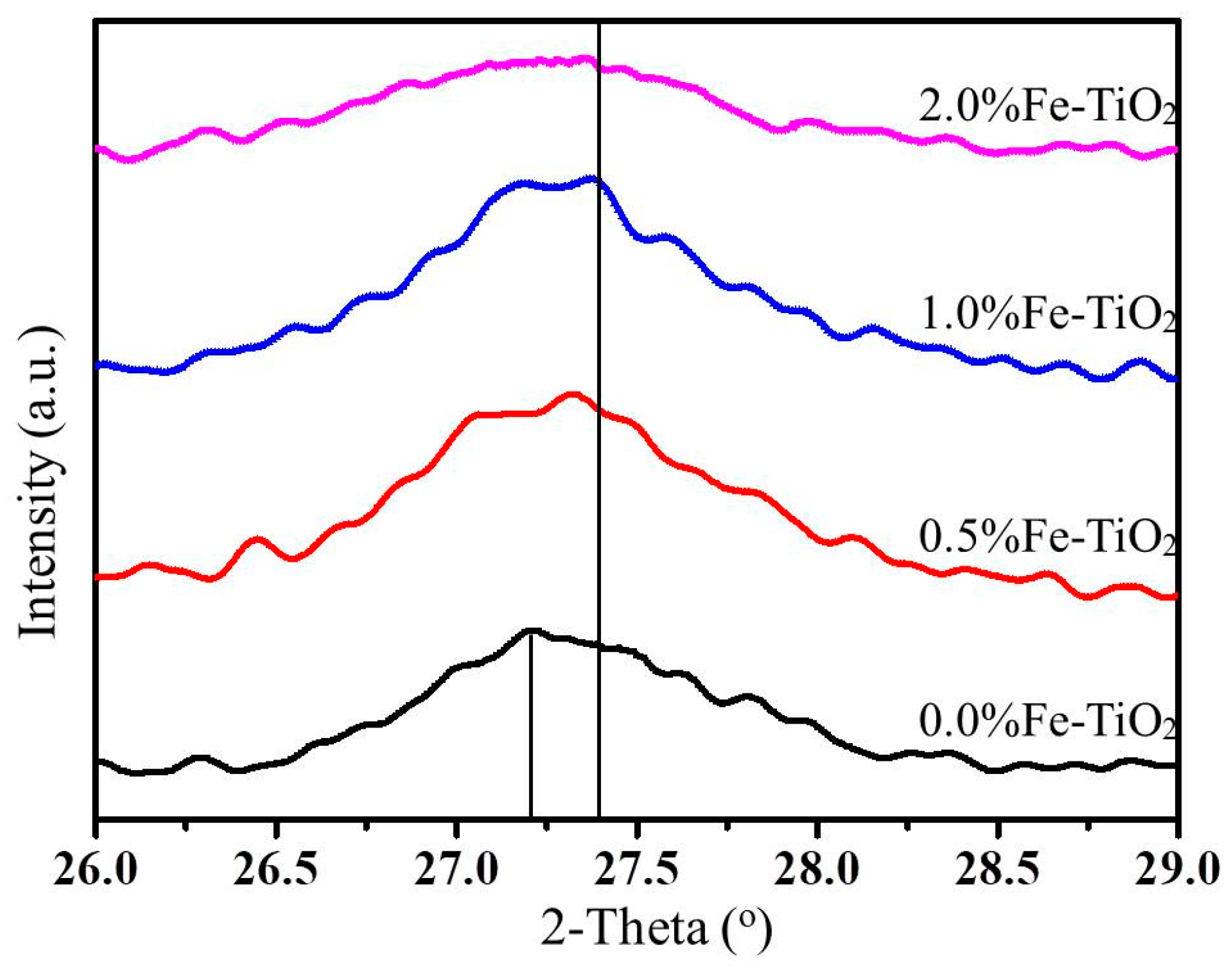
2.1. Phase Analysis of Synthesised Photocatalyst

According to the JCPDS NO.21-1276, the diffraction peaks at 2θ = 27.4°, 36.0°, 41.3°, 54.5°, 62.9°, 69.1° correspond to the (110), (101), (111), (211), (220), (301) facets of rutile TiO2, respectively.
As displayed in Figure 2, the XRD spectrum of four synthesized photocatalysts was well matched with the standard rutile TiO2 XRD patterns. It should be noted that no crystalline phase ascribed to iron oxide could be found in the XRD patterns. There are two reasons responsible for this result: (1) Fe content in the synthesized photocatalysts was below the detection limit of this technique; (2) Fe3+ ions might have substituted Ti4+ ions and incorporated into the crystal lattice of TiO2, because the radius of Ti4+ was similar to the Fe3+ ions (Fe3+: 0.65Å, Ti4+: 0.61Å) [49,50]. More, accurately, the XRD spectrum was in favour of the second reason. The introduction of Fe3+ would slightly affect the crystal structure of synthesized photocatalyst, which would lead to the peak slightly shifting. The position of the facet (110) peak slightly shifted from 27.2°to 27.4° (see Figure 3), which probably indicated that Fe3+ ions were incorporated into the TiO2 lattice.
The Raman spectrum of synthesised photocatalysts was reported in Figure 4. The rutile structure had two TiO2 molecules in the unit cell with the space group D 4 h 14 (P42/mnm). The frequencies of the Raman bands observed were located at ~143 cm−1 (B1g), ~447 cm−1 (Eg), ~612 cm−1 (A1g) and ~235 cm−1 (anomalously), which were well in agreement with previous published work [51,52,53]. The Raman spectrum further demonstrated that the synthesized photocatalyst was Rutile phase. The strong anomalously broad band about 235 cm−1 of Rutile has been extensively investigated, and is generally assigned as a multi-photon process [54]. The introduction of Fe didn’t significantly affect the lattice structure of Rutile TiO2 as displayed in Figure 4. Nevertheless, a slightly blue-shift of the Raman peak (Eg) was observed. In addition, the intensity of the Eg peak decreased and full width at half maxima (Eg and A1g) increased with the increase of Fe content. The Eg mode was much more sensitive to oxygen vacancies as they were related to planar O–O interactions [51]. Combining the broadening and shifting of the characteristic diffraction peaks of d110, this indicates that the iron ions appeared to be doped into the lattice structure of TiO2, which leads to the generation of oxygen vacancies in order to compensate for the charge [39,55].

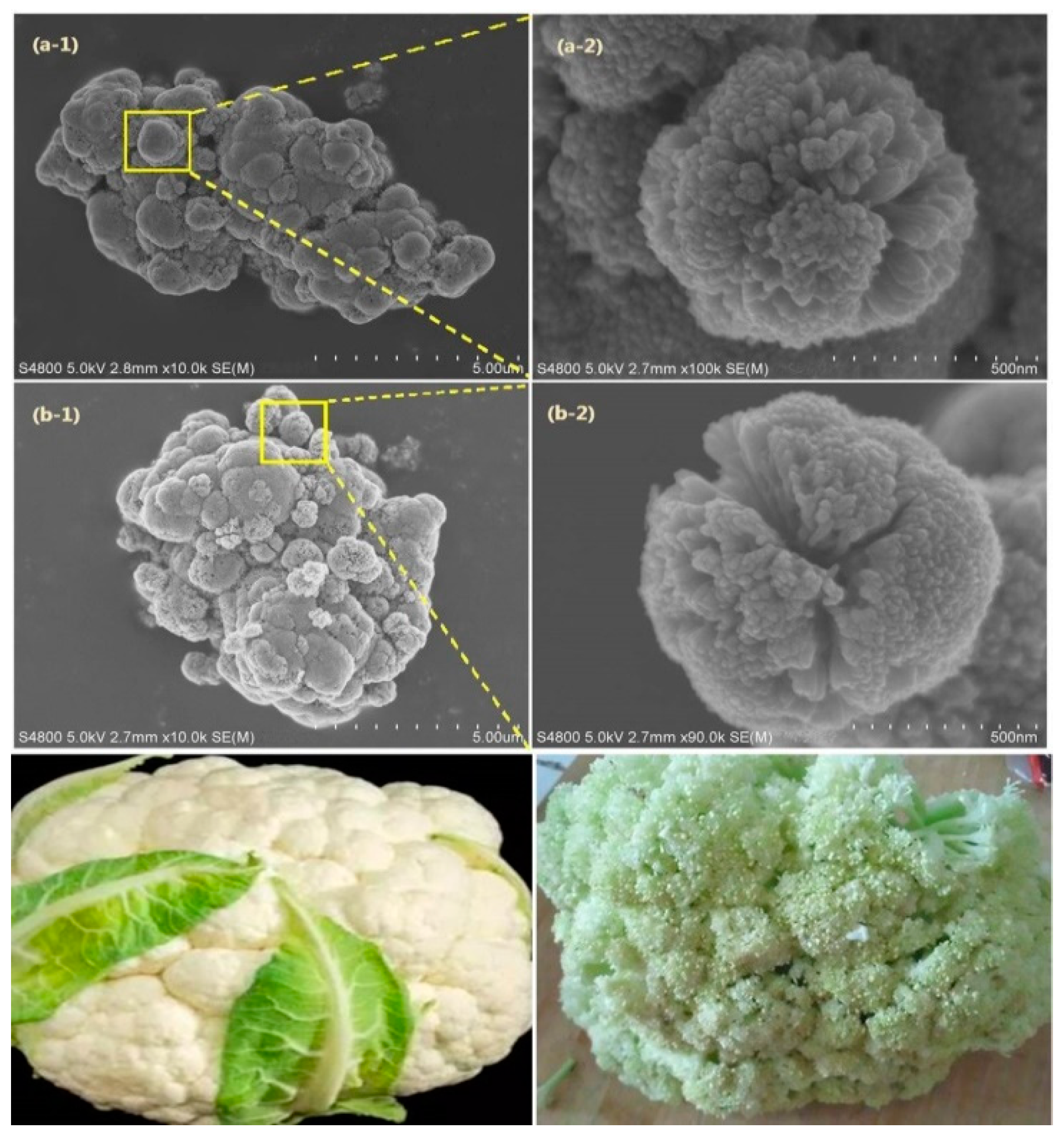
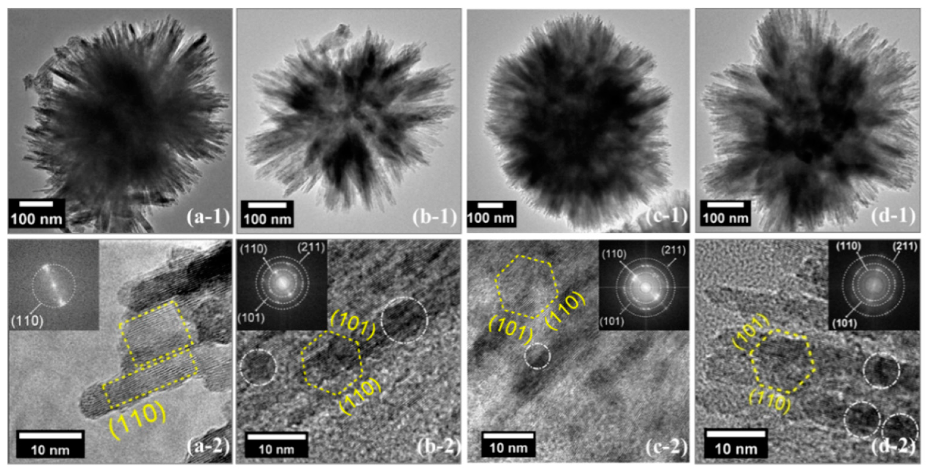
2.2. The Morphology of Synthesised Photocatalysts

Figure 5 shows the representative SEM images of synthesised photocatalyst. The morphology of photocatalyst was like a cauliflower bud at Nano-size. The synthesised nanoflower photocatalysts were assembled in irregular slices and lattice fringes were clearly visible as showed in Figure 6. All the synthesised photocatalysts contained the lattice fringe spacing 0.324 nm, which corresponded to the (110) lattice plane of rutile TiO2. Though the SAED pattern of Fe, doped photocatalysts demonstrated the existence of (211) lattice facets, the HRTEM images did not clearly show them. It is probably because of their narrow fringe spacing (0.169 nm). In addition, the electron diffraction results insets in Figure 6 (a-2, b-2, c-2, d-2) indicated that all samples were highly crystalline, which was consistent with the XRD results.

2.3. The Performance of the Synthesized Photocatalyst

The performances of synthesized photocatalysts were evaluated by the decomposition of methyl orange (MO) under the UV light irradiation. The degradation curves of MO as a function of irradiation time are shown in Figure 7. Compared to the control experiment (without photocatalyst, green line), the concentration of MO demonstrated a downward trend with the increase of irradiation time. The photocatalyst 0.5%Fe-TiO2 presented the highest activity, the degradation rate of MO was about 90% under 40 min of UV light irradiation. The photocatalyst 1.0% Fe-TiO2 and 2.0% Fe-TiO2 exhibited degradation rates of 77% and 73% under 40 min of UV light irradiation, respectively. The degradation rate of MO for 0.0%Fe-TiO2 was about 62% under the same irradiation time, which was the lowest among the four synthesized photocatalyst. Introduction of iron element into rutile TiO2 seemed beneficial to the degradation of MO. However, the photocatalytic performance of synthesized photocatalyst was decreased with the increase of Fe concentration; the optimal concentration of Fe was 0.5%. The MO photo-degradation kinetic study was presented in Figure 8. The reaction rate constants were in order: 0.5% Fe-TiO2, 1.0% Fe-TiO2, 2.0% Fe-TiO2 and 0.0%Fe-TiO2. The sequence of the reaction rate constants was in line with the activity of the synthesised photocatalyst.
It is difficult to compare the results reported in the literature, because the catalyst preparation methods and the experimental conditions were usually different. Tong et al. [56] reported a Fe-doped Anatase for the degradation of MO. In their work, at the optimal doping levels of Fe3+ (0.1%) and 6h UV light irradiation, the degradation rate of MO was 79%; under the same reaction condition, the degradation rate of MO by commercial photocatalyst P25 was only 70%. Leong et al. prepared a Ni(OH)2 decorated rutile TiO2 photocatalyst and the highest removal rates of model compound tetracycline was 68% under 2 h visible light irradiation [29]. So far, our photocatalyst seems to have presented the prominent photoactivity for a decomposing organic compound in wastewater.

3. Discussion

The Fe doped cauliflower-like rutile TiO2 photocatalysts could significantly increase the photo-degradation rate of MO under the UV irradiation. In this section, we tentatively discussed the reason for the incremental photocatalytic activity of Fe-doped rutile TiO2 photocatalyst.
The nitrogen adsorption-desorption and pore diameter distribution is shown in Figure 9. All the samples could be categorized as isotherms of type IV, indicating the presence of mesoporous materials according to the International Union of Pure and Applied Chemistry classification [57]. H3-type hysteresis loops were obtained, which implied the formation slit-like pores that were associated with nanobeam aggregation [58].
As indicated in Table 1, the specific surface areas of the Fe-doped photocatalysts were larger than that of the control sample (0.0% Fe-TiO2). A Bigger and more specific surface area benefitted the adsorption of reactants, because it offered more active sites for photocatalytic reaction. It is worth noting that the specific surface area of Fe-doped photocatalysts decreased with the increment of Fe concentration. Other researchers have also observed a similar phenomenon. They consider the reason for this increased surface area of Fe-doped TiO2 may be explained as follows: The decreased lattice spacing of TiO2 resulting from Fe dopant changes the pore diameter and pore volume of synthesized photocatalysts, which further increases the surface area of Fe-doped TiO2 [56,59].
Due to the small doped Fe concentration, no crystalline phase attributed to iron oxide could be found in the surface of rutile TiO2 by the aforementioned catalysts characterization. Hence, X-ray photoelectron spectroscopy (XPS) measurements were carried out to study the chemical composition and the elemental valence state on the surface of the synthesized photocatalysts. As expected, O1s and Ti2p peaks could be clearly observed, but no obvious Fe2p peak could be found (see Figure 10). XPS measurement suggested that the introduced iron element did not exist on the surface of the synthesized photocatalyst.
In order to investigate the presence of Fe, EDX and HAADF-STEM characterization of 0.0% Fe-doped TiO2 and 0.5% Fe-TiO2 were carried out (see Figure 11). It was found that there was no energy spectrum of Fe in 0.0% Fe-doped TiO2 (Figure 11a), while a small amount of Fe element existed in the spectrum of 0.5% Fe-TiO2 sample (Figure 11b). The high angle on the annular dark field image of scanning transmission electron microscope (HAADF-STEM shown in Figure 11c–f) also demonstrated the presence of the Fe element.
Therefore, it is reasonable to speculate that the introduced iron element was incorporated into the crystal lattice of rutile TiO2. The radius of Fe3+ (0.65Å) was similar to that of Ti4+ (0.61Å), so less Fe3+ ions could be easily doped into the crystal lattice of TiO2 and have caused the slight disorder of the rutile phase structure. This slight disorder was demonstrated by XRD measurement (see Figure 3). The lattice disorder would have generated surface defects (e.g., oxygen vacancies) in the crystal structure, which was in favour of the photocatalytic reaction.
It is generally accepted that the introduction of transition metal ions can result in lattice disorder, which further leads to a narrower band gap and the formation of a doping energy level between conduction and valence bands of TiO2 [60,61]. We carried out the UV-Vis diffuse refection characterization to confirm the decrease of band-gap of Fe-TiO2 samples. All the samples exhibited absorption in the ultraviolet and visible range. For Fe-TiO2 samples, an obvious red shift at 400–500 nm was observed in Figure 12a. The band gap decreased from 3.04 eV for 0.0% Fe-TiO2 to 2.98 eV for 2.0% Fe-TiO2 as showed in Figure 12b. This further proved that Fe had been doped into the TiO2 lattice.
This view was further demonstrated by our density functional theory (DFT) calculation. A new energy level and narrower band gap signified high separation probability of the photoinduced electron-hole pairs in the TiO2 semiconductor photocatalysts. The band gaps of synthesized photocatalysts were calculated by the VCA approach based on DFT. The calculation suggested that the introduction of Fe into the TiO2 lattice could narrow the band gap of TiO2 (see Figure 13) and with an increase in the Fe dopant concentration, the calculated band gap at G (gamma point) decreased accordingly. This was caused by the conduction band minimum (CBM), which moved down. It should be noted that extremely narrow band gap implied the high recombination rate of photo-hole pairs, which was also averse to the photocatalytic reaction. Therefore, there was an optimal band gap energy value that corresponded to the highest photocatalytic activity. Namely, an optimal introduced Fe concentration needed to be determined for the optimal band gap energy, which corresponded to the highest photocatalytic activity. In this study, the optimal introduced Fe concentration was 0.5%wt.
There was a disparity that existed between the result of the DFT calculation and that of the experiment. However, this difference was also observed by other researchers [62,63,64,65,66]. The disparity can be explained by not considering the discontinuity in the exchange-correlation potential in the DFT calculation [63,67]. Nevertheless, the DFT calculation results were still advisable for qualitative analysis and did not affect the accuracy of the comparison of the related properties of crystals [61,68].
The doping mechanism of in-situ synthesis was also proposed as below. In the catalyst synthesis process, Ti2O3 nanostructure was first formed via TiCl3 hydrolysis in acidic aqueous solution containing excessive Cl, which had a strong reducing ability. According Fe 3 + φ = 0.77 v Fe 2 + φ = 0.447 v Fe , electrode potential of Fe 3 + Fe was φ = 0.0367 v . The electrode potential of Ti 4 + Ti 3 + was −0.37v. Once the Fe3+ ions were in contact with Ti2O3 deposit in acidic environment, they were easily reduced to Fe by Ti2O3. Meanwhile, corresponding Ti2O3 was oxidized into TiO2. Oxygen vacancies, described by standard Kröger-Vink notation, were created during this chemical reduction [52]. The oxygen vacancies would slowly disappear when the material was exposed to air. However, Fe3+ acted to stabilize oxygen vacancies. This mild in-situ redox process could be described by the following formula [49,52]:
3 Ti 2 O 3 + 2 Fe 3 + + 3 H 2 O 2 Fe 0 + 6 Ti O 2 + 6 H +
Ti 2 O 3 + 1 2 O 2 = 2 Ti O 2
O O X TiO 2 V O ¨ + 1 2 O 2 ( g ) + 2 e
2 Fe + 3 2 O 2 = Fe 2 O 3
Fe 2 O 3 Ti O 2 2 Fe Ti + 3 O O X + V O ¨
Fe 2 O 3 + 1 2 O 2 ( g ) + 2 e TiO 2 2 Fe Ti + 4 O O X
where V O × represents an O 2 ion in the oxygen lattice site, V O ¨ is an oxygen vacancy, Fe Ti indicates Fe3+ ion in the titanium lattice site, which can stabilize the oxygen vacancies as ionic charge-compensating species. Alternatively, the Fe3+ acceptor can be compensated by a decrease in the concentration of free electrons in the TiO2.
Other researchers have used the similarly method to synthesize the photocatalyst [69]. However, in their study, the introduced metals were loaded on to the surface rather than doped into the TiO2 lattice. The probably reason is that, in their work, the radii of selected metals (Pt, Au, Ru, etc.) ions are much larger than that of Ti4+. Hence, selected metal ions couldn’t substitute the Ti4+ in the rutile TiO2 lattice.

4. Materials and Methods

4.1. Photocatalysts Synthesis

Four photocatalysts have been synthesised, among which one is the control sample, the other three are Fe-doped rutile TiO2 photocatalysts. The iron mass fraction of doped rutile TiO2 photocatalyst was 0.5% (0.5% Fe-TiO2), 1.0% (1.0% Fe-TiO2) and 2.0% (2.0% Fe-TiO2), respectively.
For control sample synthesis, first, 20 g TiCl3 solution (Alfa Aesar, Haverhill, MA, USA, 20% in 3% hydrochloric acid aqueous solution) was mixed with 60 g of 30 wt% NaCl aqueous solution. Then, the mixed solution was heated at 100 °C for 12 h under N2 atmosphere to get the blue deposit (Ti2O3). This process could be described by the following equation:
Ti 3 + + H 2 O = Ti ( OH ) 3 + 3 H +
2 Ti ( OH ) 3 Ti 2 O 3 + H 2 O
Next, the blue deposit was quickly washed by deionized water several times to remove the unreacted TiCl3. The existence of TiCl3 (purple) was identified by the colour of washed deionized water (purple to colourless). Afterwards, the washed blue deposit was re-dispersed in deionized water under an acidic environment and exposed to the air at room temperature for 24 h, which could oxide the blue deposit (Ti2O3) and turn it into white deposit (rutile TiO2). The auto-oxidation process could be described according to the Kröger–Vink formula [70]:
Ti 2 O 3 + 1 2 O 2 = 2 Ti O 2
Finally, the white deposit (rutile TiO2) was separated by filtration, the Cl ions were washed off by deionized water. The existence of Cl ions was identified by AgNO3 solution (0.1mol/L). The synthesized sample was vacuum-dried at 80 °C for 24 h and was used as a control sample.
For the Fe doped photocatalyst, the first two steps were the same as the control sample synthesis steps. Third step, the washed blue deposit (Ti2O3) was re-dispersed in deionized water and the suspension was heated to 80 °C with N2 atmosphere protection in a water bath. Fourth step, the calculated amount of 0.01 mol/L FeCl3·6H2O (AR, Alfa Aesar, Haverhill, MA, USA) aqueous solution was subsequently added into the blue suspension (Ti2O3) at 80 °C. After being maintained at 80 °C for 3 h, the mixture was naturally cooled to room temperature and exposed to air for 24 h. Finally, the white deposit (rutile TiO2) was separated by filtration, the Cl ions were washed off by deionized water. The existence of Cl ions was identified by AgNO3 solution (0.1mol/L). The synthesized samples were vacuum-dried at 80 °C for 24 h and were used as the Fe-doped photocatalyst.

4.2. Photocatalysts Characterization

X-ray powder diffraction (XRD) patterns were measured on a PANalytical/Empyrean diffractometer at room temperature. The patterns were recorded over the angular range 10–80° (2θ), using a scanning step 2°/s and Cu(Kα) radiation (λ = 1.5418 Å) with working voltage and current of 40 kV and 200 mA, respectively. Raman spectra were obtained on a RENISHAW (Staffordshire, UK). The wavelength of the laser was 532 nm and scanning range was 100–1000 cm−1. Exposure time was 1 s. Scanning electron micrographs (SEM) were recorded with a Hitachi S-3400N (Tokyo, Japan), which was used to determine the morphology of the sample. Transmission electron microscopy (TEM) and high-resolution transmission electron microscope (HRTEM) energy-dispersive X-ray spectroscopy (EDX) and High angle annular dark field image of scanning transmission electron microscope (HAADF-STEM) were performed with a FEI TECNAI F30 microscope (Hillsboro, OR, USA). The control voltage was 300 kV, and samples were dropped on a holey carbon-coated copper 400-mesh grid (2SPI, Shanghai, China). X-ray photoelectron spectroscopy (XPS) measurements were carried out on a Shimadzu/KRATOS AMICUS X-ray photoelectron spectrometer (Kyoto, Japan) with an AlKα (1486.67 eV) excitation source, which determines the existence and valence states of synthesised photocatalysts. UV-Vis diffuse refection was carried on a Perkin Elmer UV/VS/NIR Lambda 750s spectrometer (Waltham, MA, USA) to confirm band-gap of Fe-TiO2 samples. The BET surface areas (SBET) and pore diameter distribution of the synthesized photocatalysts were determined by the N2 adsorption–desorption test performed on a Micrometrics ASAP2020 analyser (Norcross, GA, USA).

4.3. Photocatalysts Evaluation

The photocatalytic performance of synthesized photocatalysts was evaluated in a homemade setup, which was equipped with a 300 W mercury lamp. Methyl orange (MO, see Figure 1) was selected as the model compound, which was illuminated by UV light (λ ≤ 420 nm).
A synthesized photocatalyst (25 mg) was suspended into a quartz tube, which contained 50 mL of MO aqueous solution (6 mg/mL). The suspension mixture was magnetically stirred for 120 min in the dark to attain the adsorption-desorption equilibrium for MO and dissolved oxygen on the surface of synthesized photocatalyst surface. Subsequently, the obtained suspensions were illuminated with UV light (λ ≤ 420 nm) under magnetic stirring. During the reaction, 1.5 mL of suspensions was collected at a regular interval. The collected sample was centrifuged to separate the photocatalyst from the suspension sample. The supernatant was transferred into a transparent cuvette and the concentration of MO was measured with a UV–vis absorption spectrometer (Beijing Purkinje General Instrument Co., Ltd., Beijing, China).
The degradation rate of MO was calculated using the following equation: Degradation rate = 100% × (CMO − C)/CMO, where CMO is the initial concentration of MO, and C is the MO concentration at the given time of irradiation, respectively. The photocatalytic degradation of MO follows the pseudo-first order decay kinetics, which can be assumed to be calculated using the following formula: ln(CMO/C) = kapp × t [38]. In this equation, kapp is the apparent pseudo-first order degradation rate constant (min−1), which can be used to measure the efficiency of the degradation of MO and the photocatalytic performance of samples.

4.4. DFT Calculation Details

The DFT calculations were performed using the plane wave based periodic DFT method as implemented in the CASTEP module of Materials Studio [71]. The electron exchange and correlation energies were treated within the Generalized Gradient Approximation in the Perdew–Burke–Ernzerhof functional (GGA-PBE). The plane wave basis was set up to 400 eV, and the Monkhorst–Pack scheme K-point sampling was set as 4 × 4 × 3. The calculated Rutile TiO2 had a tetragonal structure with lattice parameters a = b = 4.594 Å, c = 2.959 Å. A VCA approach was used to simulate our Fe-doped photocatalysts. This method allowed us to replace each atom of a certain type in the unit cell with a fictitious element with a non-integer atomic number [72]. For Fe-doped rutile TiO2, Ti atoms were replaced with virtual pseudo-potentials, Ti-Fe atoms with different Fe contents ( x ), as V V C A p s [ x ] = x V F e p s + ( 1 x ) V T i p s , but maintained the rutile crystal structure [73,74,75,76].

5. Conclusions

A mild in situ method was developed to construct an iron-doped rutile TiO2 photocatalyst for the degradation of organic dye in wastewater. The synthesized photocatalysts were like cauliflower bud at Nano-size. XRD and Raman spectrum confirmed the rutile phase of TiO2. The Fe-doped photocatalysts presented distinguished photocatalytic activity. At the optimal Fe concentration (0.5%), the degradation rate of the methyl orange was 90% under 40 min of UV light irradiation. The specific surface area of Fe doped catalysts was bigger than that of the control sample. EDX and HAADF-STEM characterization suggested that there was no energy spectrum of Fe in 0.0% Fe-doped TiO2, while a small amount of Fe element existed in the spectrum of 0.5% Fe-TiO2 sample. However, XPS indicated that the introduced iron element didn’t exist on the surface of the synthesized photocatalyst. Due to the radius of Fe3+ (0.65 Å) being similar to that of Ti4+ (0.61 Å), it was reasonable to speculate that less Fe3+ ions could be easily doped into the crystal lattice of TiO2 and cause the slight disorder of rutile phase structure. This slightly disorder was demonstrated by the slight shift of position of the facet (100) peak in the XRD measurement. The UV-Vis diffuse reflection characterization and DFT calculation further suggested that doping small amount of Fe into the lattice of rutile would lead to a narrower band gap, formation of a doping energy level between conduction and valence bands of TiO2, which is favourable for photo-decomposing the organic pollutants in waste water.
The novelty of this study can be emphasized as follows:
  • This study provided a mild and low cost method for the synthesis the Fe-doped rutile TiO2. The rutile preparation temperature did not exceed 100 °C, which was much lower than the traditional preparation calcination temperature (e.g., 600 °C). TiCl3 was used as a titanium source other than expensive Ti(OC4H9)4. To our knowledge, doping Fe into rutile TiO2 using this method was reported first in this paper.
  • The synthesized photocatalysts presented the prominent photoactivity for decomposing organic dye in wastewater. It is difficult to compare with those results reported in the literature, because the catalysts preparation methods and the experimental conditions were usually different. Tong et al. [58] reported a Fe-doped Anatase for the degradation of MO. In their work, at the optimal doping levels of Fe3+ (0.1%) and 6 h UV light irradiation, the degradation rate of MO was 79%; under the same reaction condition, the degradation rate of MO by commercial photocatalyst P25 was only 70%. Leong et al. prepared a Ni(OH)2 decorated rutile TiO2 photocatalyst and the highest removal rates of model compound tetracycline was 68% under 2 h visible light irradiation [59]. So far, our photocatalyst seems to have presented the prominent photoactivity for decomposing organic compounds in wastewater.

Author Contributions

Data curation, Y.Z.; investigation, X.S. and S.H.; methodology, H.J.; software, H.L.; supervision, C.L. visualization, X.L.; writing—original draft, H.H.; writing—review and editing, H.H.

Funding

This research was funded by the Program of Higher-level Talents of IMU (21300-5185109), Inner Mongolia Education Department Key Project (NJZZ16015), and Inner Mongolia Natural Science Foundation (2016MS0216).

Acknowledgments

The authors are grateful for advice from Rui Gao. We also acknowledge Synfuels China, Co. Ltd. for the free use of their Super-Server for the DFT calculations.

Conflicts of Interest

The authors declare no conflicts of interest.

References

  1. Jorfi, S.; Barzegar, G.; Ahmadi, M.; Soltani, R.D.C.; Takdastan, A.; Saeedi, R.; Abtahi, M. Enhanced coagulation-photocatalytic treatment of Acid red 73 dye and real textile wastewater using UVA/synthesized MgO nanoparticles. J. Environ. Manag. 2016, 177, 111–118. [Google Scholar] [CrossRef]
  2. Ellouze, E.; Tahri, N.; Amar, R.B. Enhancement of textile wastewater treatment process using nanofiltration. Desalination 2012, 286, 16–23. [Google Scholar] [CrossRef]
  3. Akpan, U.G.; Hameed, B.H. Parameters affecting the photocatalytic degradation of dyes using TiO2-based photocatalysts: A. review. J. Hazard. Mater. 2009, 170, 520–529. [Google Scholar] [CrossRef]
  4. Özcan, A.; Ömeroğlu, Ç.; Erdoğan, Y.; Özcan, A.S. Modification of bentonite with a cationic surfactant: An adsorption study of textile dye Reactive Blue 19. J. Hazard. Mater. 2007, 140, 173–179. [Google Scholar] [CrossRef]
  5. Jafari, A.J.; Kakavandi, B.; Kalantary, R.R.; Gharibi, H.; Asadi, A.; Azari, A.; Babaei, A.A.; Takdastan, A. Korean Application of mesoporous magnetic carbon composite for reactive dyes removal: Process optimization using response surface methodology. J. Chem. Eng. 2016, 33, 2878–2890. [Google Scholar]
  6. Ahmadi, M.; Ramavandi, B.; Sahebi, S. Efficient degradation of a biorecalcitrant pollutant from wastewater using a fluidized catalyst-bed reactor. Chem. Eng. Commun. 2015, 202, 1118–1129. [Google Scholar] [CrossRef]
  7. Konstantinou, I.K.; Albanis, T.A. TiO2-assisted photocatalytic degradation of azo dyes in aqueous solution: Kinetic and mechanistic investigations: A. review. Appl. Catal. B Environ. 2004, 49, 1–14. [Google Scholar] [CrossRef]
  8. Tang, W.Z.; An, H. UV/TiO2 photocatalytic oxidation of commercial dyes in aqueous solutions. Chemosphere 1995, 31, 4158–4170. [Google Scholar] [CrossRef]
  9. Arslan, I.; Balcioglu, A.I. Advanced oxidation of raw and biotreated textile industry wastewater with O3, H2O2/UV-C and their sequential application. J. Chem. Technol. Biotechnol. 2001, 76, 53–60. [Google Scholar] [CrossRef]
  10. Hao, O.J.; Kim, H.; Chiang, P.C. Decolorization of wastewater. Crit. Rev. Environ. Sci. Technol. 2000, 30, 449–502. [Google Scholar] [CrossRef]
  11. Sleiman, M.; Vildozo, D.; Ferronato, C.; Chovelon, J.-M. Photocatalytic degradation of azo dye Metanil Yellow: Optimization and kinetic modeling using a chemometric approach. Appl. Catal. B Environ. 2007, 77, 1–11. [Google Scholar] [CrossRef]
  12. Slokar, Y.M.; Le Marechal, A.M. Methods of decoloration of textile wastewaters. Dyes Pigments 1998, 37, 335–356. [Google Scholar] [CrossRef]
  13. Kuo, W.G. Decolorizing dye wastewater with Fenton’s reagent. Water Res. 1992, 26, 881–886. [Google Scholar] [CrossRef]
  14. Ince, N.H.; Gonenc, D.T. Treatability of a textile azo dye by UV/H2O2. Environ. Technol. 1997, 18, 179–185. [Google Scholar] [CrossRef]
  15. Forgacs, E.; Cserhati, T.; Oros, G. Removal of synthetic dyes from wastewaters: A. review. Environ. Int. 2004, 30, 953–971. [Google Scholar] [CrossRef] [PubMed]
  16. Ani, I.J.; Akpan, U.G.; Olutoye, M.A.; Hameed, B.H. Photocatalytic degradation of pollutants in petroleum refinery wastewater by TiO2 and ZnO-based photocatalysts: Recent development. J. Clean. Prod. 2018, 205, 930–954. [Google Scholar] [CrossRef]
  17. Chakrabarti, S.; Dutta, B.K. Photocatalytic degradation of model textile dyes in wastewater using ZnO as semiconductor catalyst. J. Hazard. Mater. 2004, 112, 269–278. [Google Scholar] [CrossRef]
  18. Reddy, M.P.; Venugopal, A.; Subrahmanyam, M. Hydroxyapatite photocatalytic degradation of calmagite (an azo dye) in aqueous suspension. Appl. Catal. B Environ. 2007, 69, 164–170. [Google Scholar] [CrossRef]
  19. Saquiba, M.; Tariqa, M.A.; Faisala, M.; Muneer, M. Photocatalytic degradation of two selected dye derivatives in aqueous suspensions of titanium dioxide. Desalination 2008, 219, 301–311. [Google Scholar] [CrossRef]
  20. Jallouli, N.; Pastrana-Martínez, L.M.; Ribeiro, A.R.; Moreira, N.F.; Faria, J.L.; Hentati, O.; Silva, A.M.; Ksibi, M. Heterogeneous photocatalytic degradation of ibuprofen in ultrapure water, municipal and pharmaceutical industry wastewaters using a TiO2/UV-LED system. Chem. Eng. J. 2018, 334, 976–984. [Google Scholar] [CrossRef]
  21. Mills, A.; Hunte, L. An overview of semiconductor photocatalysis. J. Photochem. Photobiol. A Chem. 1997, 108, 1–35. [Google Scholar] [CrossRef]
  22. Carp, O.; Huisman, C.L.; Reller, A. Photoinduced reactivity of titanium dioxide. Prog. Solid State Chem. 2004, 32, 33–177. [Google Scholar] [CrossRef]
  23. Reddy, D.R.; Dinesh, G.K.; Anandan, S.; Sivasankar, T. Sonophotocatalytic treatment of Naphthol Blue Black dye and real textile wastewater using synthesized Fe doped TiO2. Chem. Eng. Process 2016, 99, 10–18. [Google Scholar] [CrossRef]
  24. Ge, M.; Cai, J.; Iocozzia, J.; Cao, C.; Huang, J.; Zhang, X.; Shen, J.; Wang, S.; Zhang, S.K.-Q.; Zhang, Y.L.; Lin, Z. A review of TiO2 nanostructured catalysts for sustainable H2 generation. Int. J. Hydrogen Energy 2017, 42, 8418–8449. [Google Scholar] [CrossRef]
  25. Liu, L.; Zhao, H.; Andino, J.M.; Li, Y. A review of TiO2 nanostructured catalysts for sustainable H2 generation. ACS Catal. 2012, 2, 1817–1828. [Google Scholar] [CrossRef]
  26. Luttrell, T.; Halpegamage, S.; Tao, J.; Kramer, A.; Sutter, E.; Batzill, M. Why is anatase a better photocatalyst than rutile?—Model studies on epitaxial TiO2 films. Sci. Rep. 2014, 4, 4043. [Google Scholar] [CrossRef]
  27. Zhang, J.; Zhou, P.; Liu, J.; Yu, J. New understanding of the difference of photocatalytic activity among anatase, rutile and brookite TiO2. Phys. Chem. Chem. Phys. 2014, 16, 20382–20386. [Google Scholar] [CrossRef] [PubMed]
  28. Kakuma, Y.; Nosaka, A.Y.; Nosaka, Y. Difference in TiO2 photocatalytic mechanism between rutile and anatase studied by the detection of active oxygen and surface species in water. Phys. Chem. Chem. Phys. 2015, 17, 18691–18698. [Google Scholar] [CrossRef] [PubMed]
  29. Leong, S.; Li, D.; Hapgood, K.; Zhang, X.; Wang, H. Ni (OH)2 decorated rutile TiO2 for efficient removal of tetracycline from wastewater. Appl. Catal. B Environ. 2016, 198, 224–233. [Google Scholar] [CrossRef]
  30. Yang, K.; Zhu, J.M.; Zhu, J.J.; Huang, S.S.; Zhu, X.H.; Ma, G.B. Sonochemical synthesis and microstructure investigation of rod-like nanocrystalline rutile Titania. Mater. Lett. 2003, 57, 4639–4642. [Google Scholar] [CrossRef]
  31. Yang, S.F.; Liu, Y.H.; Guo, Y.P.; Zhao, J.Z.; Xu, H.F.; Wang, Z.C. Preparation of rutile Titania nanocrystals by liquid method at room temperature. Mater. Chem. Phys. 2002, 77, 501–506. [Google Scholar] [CrossRef]
  32. Litter, M.I. Heterogeneous photocatalysis: Transition metal ions in photocatalytic systems. Appl. Catal. B Environ. 1999, 23, 89–114. [Google Scholar] [CrossRef]
  33. Yamashita, H.; Harada, M.; Misaka, J.; Takeuchi, M.; Neppolian, B.; Anpo, M. Photocatalytic degradation of organic compounds diluted in water using visible light-responsive metal ion-implanted TiO2 catalysts: Fe ion-implanted TiO2. Catal. Today 2003, 84, 191–196. [Google Scholar] [CrossRef]
  34. Wang, C.C.; Zhang, Z.; Ying, J.Y. Photocatalytic decomposition of halogenated organics over nanocrystalline Titania. Nanostruct. Mater. 1997, 9, 583–586. [Google Scholar] [CrossRef]
  35. Lepore, G.P.; Langford, C.H.; Vichova, J.; Vlcek, A. Photochemistry and picosecond absorption spectra of aqueous suspensions of a polycrystalline titanium dioxide optically transparent in the visible spectrum. J. Photochem. Photobiol. A Chem. 1993, 75, 67–75. [Google Scholar] [CrossRef]
  36. Choi, W.; Termin, A.; Hoffmann, M.R. Effects of metal-ion dopants on the photocatalytic reactivity of quantum-sized TiO2 particles. Angew. Chem. Int. Ed. 1994, 33, 1091–1096. [Google Scholar] [CrossRef]
  37. Dong, Y.L.; Won, J.L.; Jae Sung, S.; Jung, H.K.; Yang, S.K. Electronic surface state of TiO2 electrode doped with transition metals, studied with cluster model and DV-X_ method. Comput. Mater. Sci. 2004, 30, 383–388. [Google Scholar]
  38. Mesgari, Z.; Gharagozlou, M.; Khosravi, A.; Gharanjig, K. Synthesis, characterization and evaluation of efficiency of new hybrid Pc/Fe-TiO2 nanocomposite as photocatalyst for decolorization of methyl orange using visible light irradiation. Appl. Catal. A Gen. 2012, 411, 139–145. [Google Scholar] [CrossRef]
  39. Vásquez, G.C.; Peche-Herrero, M.A.; Maestre, D.; Alemán, B.; Ramírez-Castellanos, J.; Cremades, A.; Piqueras, J. Influence of Fe and Al doping on the stabilization of the anatase phase in TiO2 nanoparticles. J. Mater. Chem. C 2014, 2, 10377–10385. [Google Scholar] [CrossRef]
  40. Yu, J.G.; Zhou, M.H.; Yu, H.G.; Zhang, Q.J.; Yu, Y. Enhanced photoinduced super-hydrophilicity of the sol–gel-derived TiO2 thin films by Fe-doping. Mater. Chem. Phys. 2006, 95, 193–196. [Google Scholar] [CrossRef]
  41. Wang, C.Y.; Bottcher, C.; Bahnemann, D.W.; Dohrmann, J.K. A comparative study of nanometer sized Fe (III)-doped TiO2 photocatalysts: Synthesis, characterization and activity. J. Mater. Chem. 2003, 13, 2322–2329. [Google Scholar] [CrossRef]
  42. Zhou, M.H.; Yu, J.G.; Cheng, B. Effects of Fe-doping on the photocatalytic activity of mesoporous TiO2 powders prepared by an ultrasonic method. J. Hazard. Mater. 2006, 137, 1838–1847. [Google Scholar] [CrossRef] [PubMed]
  43. Low, J.; Cheng, B.; Yu, J. Surface modification and enhanced photocatalytic CO2 reduction performance of TiO2: A. review. Appl. Surf. Sci. 2017, 392, 658–686. [Google Scholar] [CrossRef]
  44. Kumar, K.N.; Pr Keizer, K.; Burggraaf, A.J.; Okubo, T.; Nagamoto, H.; Morooka, S. Densification of nanostructured titania assisted by a phase transformation. Nature 1992, 358, 48–51. [Google Scholar] [CrossRef]
  45. Hardcastle, F.D.; Ishihara, H.; Sharma, R.; Biris, A.S. Photoelectroactivity and Raman spectroscopy of anodized titania (TiO2) photoactive water-splitting catalysts as a function of oxygen-annealing temperature. J. Mater. Chem. 2011, 21, 6337–6345. [Google Scholar] [CrossRef]
  46. Yurdakal, S.; Palmisano, G.; Loddo, V.; Alagoz, O.; Augugliaro, V.; Palmisano, L. Selective photocatalytic oxidation of 4-substituted aromatic alcohols in water with rutile TiO2 prepared at room temperature. Green Chem. 2009, 11, 510–516. [Google Scholar] [CrossRef]
  47. Ding, K.; Miao, Z.; Hu, B.; An, G.; Sun, Z.; Han, B.; Liu, Z. Study on the anatase to rutile phase transformation and controlled synthesis of rutile nanocrystals with the assistance of ionic liquid. Langmuir 2010, 26, 10294–10302. [Google Scholar] [CrossRef]
  48. Li, Y.; Liu, J.; Jia, Z. Morphological control and photodegradation behavior of rutile TiO2 prepared by a low-temperature process. Mater. Lett. 2006, 60, 1753–1757. [Google Scholar] [CrossRef]
  49. Wu, Q.; Zheng, Q.; van de Krol, R. Creating oxygen vacancies as a novel strategy to form tetrahedrally coordinated Ti4+ in Fe/TiO2 nanoparticles. J. Phys. Chem. C 2012, 116, 7219–7226. [Google Scholar] [CrossRef]
  50. Choudhury, B.; Verma, R.; Choudhury, A. Oxygen defect assisted paramagnetic to ferromagnetic conversion in Fe doped TiO2 nanoparticles. RSC Adv. 2014, 4, 29314–29323. [Google Scholar] [CrossRef]
  51. Salari, M.; Konstantinov, K.; Liu, H.K. Enhancement of the capacitance in TiO2 nanotubes through controlled introduction of oxygen vacancies. J. Mater. Chem. 2011, 21, 5128–5133. [Google Scholar] [CrossRef]
  52. Wu, Q.; Van De Krol, R. Selective photoreduction of nitric oxide to nitrogen by nanostructured TiO2 photocatalysts: Role of oxygen vacancies and iron dopant. J. Am. Chem. Soc. 2012, 134, 9369–9375. [Google Scholar] [CrossRef] [PubMed]
  53. Parker, J.C.; Siegel, R.W. Calibration of the Raman spectrum to the oxygen stoichiometry of nanophase TiO2. Appl. Phys. Lett. 1990, 57, 943–945. [Google Scholar] [CrossRef]
  54. Ma, H.L.; Yang, J.Y.; Dai, Y.; Zhang, Y.B.; Lu, B.; Ma, G.H. Raman study of phase transformation of TiO2 rutile single crystal irradiated by infrared femtosecond laser. Appl. Surf. Sci. 2007, 253, 7497–7500. [Google Scholar] [CrossRef]
  55. Zhang, J.; Chen, X.; Shen, Y.; Li, Y.; Hu, Z.; Chu, J. Synthesis, surface morphology, and photoluminescence properties of anatase iron-doped titanium dioxide nano-crystalline films. Phys. Chem. Chem. Phys. 2011, 13, 13096–13105. [Google Scholar] [CrossRef] [PubMed]
  56. Tong, T.; Zhang, J.; Tian, B.; Chen, F.; He, D. Preparation of Fe3+-doped TiO2 catalysts by controlled hydrolysis of titanium alkoxide and study on their photocatalytic activity for methyl orange degradation. J. Hazard. Mater. 2008, 155, 572–579. [Google Scholar] [CrossRef]
  57. Sing, K.S. Siemieniewska. Reporting physisorption data for gas/solid systems with special reference to the determination of surface area and porosity. Pure Appl. Chem. 1985, 57, 603–619. [Google Scholar] [CrossRef]
  58. He, Z.; Cai, Q.; Fang, H.; Situ, G.; Qiu, J.; Song, S.; Chen, J. Photocatalytic activity of TiO2 containing anatase nanoparticles and rutile nanoflower structure consisting of nanorods. J. Environ. Sci. 2013, 25, 2460–2468. [Google Scholar] [CrossRef]
  59. Molea, A.; Popescu, V.; Rowson, N.A.; Cojocaru, I.; Dinescu, A.; Dehelean, A.; Lazar, M. Correlation of physicochemical properties with the catalytic performance of fe-doped titanium dioxide powders. Ind. Eng. Chem. Res. 2015, 54, 7346–7351. [Google Scholar] [CrossRef]
  60. Tan, H.; Zhao, Z.; Niu, M.; Mao, C.; Cao, D.; Cheng, D.; Feng, P.; Sun, Z. A facile and versatile method for preparation of colored TiO2 with enhanced solar-driven photocatalytic activity. Nanoscale 2014, 6, 10216–10223. [Google Scholar] [CrossRef]
  61. Liu, X.; Gao, S.; Xu, H.; Lou, Z.; Wang, W.; Huang, B.; Dai, Y. Green synthetic approach for Ti3+ self-doped TiO2−x nanoparticles with efficient visible light photocatalytic activity. Nanoscale 2013, 5, 1870. [Google Scholar] [CrossRef]
  62. Burdett, J.K.; Hughbanks, T.; Miller, G.J.; Richardson, J.W.; Smith, J.V. Structural-electronic relationships in inorganic solids: Powder neutron diffraction studies of the rutile and anatase polymorphs of titanium dioxide at 15 and 295 K. J. Am. Chem. Soc. 1987, 109, 3639–3646. [Google Scholar] [CrossRef]
  63. Glassford, K.M.; Chelikowsky, J.R. Structural and electronic properties of titanium dioxide. Phys. Rev. B 1992, 46, 1284–1298. [Google Scholar] [CrossRef]
  64. Li, H.; Zhang, X.; Huo, Y.; Zhu, J. Supercritical preparation of a highly active S-doped TiO2 photocatalyst for methylene blue mineralization. Environ. Sci. Technol. 2007, 41, 4410–4414. [Google Scholar] [CrossRef]
  65. Wu, H.C.; Li, S.H.; Lin, S.W. Effect of Fe concentration on Fe-doped anatase TiO2 from GGA + U calculations. Int. J. Photoenergy 2012, 2012, 11270–11278. [Google Scholar] [CrossRef]
  66. Shao, G. Electronic structures of manganese-doped rutile TiO2 from first principles. J. Phys. Chem. C 2008, 112, 18677–18685. [Google Scholar] [CrossRef]
  67. Brik, M.G.; Sildos, I.; Kiisk, V. First-principles calculations of optical and electronic properties of pure and Sm3+-doped TiO2. Phys. B Condens. Matter 2010, 405, 2450–2456. [Google Scholar] [CrossRef]
  68. Lee, C.; Ghosez, P.; Gonze, X. Lattice dynamics and dielectric properties of incipient ferroelectric TiO2 rutile. Phys. Rev. B 1994, 50, 13379–13387. [Google Scholar] [CrossRef]
  69. Xie, Y.; Ding, K.; Liu, Z.; Tao Ro Sun, Z.; Zhang, H.; An, G. In situ controllable loading of ultrafine noble metal particles on titania. J. Am. Chem. Soc. 2009, 131, 6648–6649. [Google Scholar] [CrossRef] [PubMed]
  70. Su, Y.; Xin, X.; Wang, Y.; Wang, T.; Wang, X. Unprecedented catalytic performance in disordered nickel niobate through photo-synergistic promotion. Chem. Commun. 2014, 50, 4200–4202. [Google Scholar] [CrossRef]
  71. Segall, M.D.; Lindan, P.J.; Probert, M.A.; Pickard, C.J.; Hasnip, P.J.; Clark, S.J.; Payne, M.C. First-principles simulation: Ideas, illustrations and the CASTEP code. J. Phys. Condens. Matter 2002, 14, 2717–2744. [Google Scholar] [CrossRef]
  72. Johannes, M.D.; Mazin, I.I.; Parker, D.S. Effect of doping and pressure on magnetism and lattice structure of iron-based superconductors. Phys. Rev. B 2010, 82, 024527. [Google Scholar] [CrossRef] [Green Version]
  73. Yu, C.J.; Emmerich, H. An efficient virtual crystal approximation that can be used to treat heterovalent atoms, applied to (1 − x) BiScO3–xPbTiO3. J. Phys. Condens. Matter 2007, 19, 306203. [Google Scholar] [CrossRef]
  74. Pople, J.A.; Gill, P.M.W.; Handy, N.C. Spin-unrestricted character of Kohn-Sham orbitals for open-shell systems. Int. J. Quantum Chem. 1995, 56, 303–305. [Google Scholar] [CrossRef]
  75. Íñiguez, J.; Vanderbilt, D.; Bellaiche, L. First-principles study of (BiScO3) 1−x−(PbTiO3) x piezoelectric alloys. Phys. Rev. B 2003, 67, 224107. [Google Scholar] [CrossRef]
  76. Kim, Y.M.; He, J.; Biegalski, M.D.; Ambaye, H.; Lauter, V.; Christen, H.M.; Pantelides, S.T.; Pennycook, S.J.; Kalinin, S.V.; Borisevich, A.Y. Probing oxygen vacancy concentration and homogeneity in solid-oxide fuel-cell cathode materials on the subunit-cell level. Nat. Mater. 2012, 11, 888–894. [Google Scholar] [CrossRef] [PubMed]
Figure 1. Molecular structure of MO.
Catalysts 09 00426 g001
Figure 2. XRD patterns of synthesised photocatalysts.
Catalysts 09 00426 g002
Figure 3. Partial enlarged detail of XRD patterns of synthesised photocatalysts.
Catalysts 09 00426 g003
Figure 4. Raman spectrum of synthesised photocatalysts.
Catalysts 09 00426 g004
Figure 5. Representative Scanning Electron Microscopy images of synthesized photocatalysts (a-1, a-2: Rutile TiO2; b-1, b-2: 0.5%Fe-TiO2).
Catalysts 09 00426 g005
Figure 6. TEM and HRTEM images of synthesized photocatalyst. (0.0%Fe-TiO2: a-1, a-2; 0.5%Fe-TiO2: b-1, b-2; 1.0%Fe-TiO2: c-1, c-2; and 2.0%Fe-TiO2: d-1, d-2).
Catalysts 09 00426 g006
Figure 7. Photo-degradation rate of MO as a function of UV light irradiation time.
Catalysts 09 00426 g007
Figure 8. Kinetic plots for photo-degradation of MO.
Catalysts 09 00426 g008
Figure 9. N2 adsorption-desorption and pore diameter distribution of synthesized photocatalysts; (a): 0.0% Fe-TiO2, (b): 0.5% Fe-TiO2 (c): 1.0% Fe-TiO2 (d): 2.0% Fe-TiO2.
Catalysts 09 00426 g009
Figure 10. The XPS spectra of Fe-doped photocatalysts.
Catalysts 09 00426 g010
Figure 11. EDX spectrum of 0.0% Fe-TiO2 (a) and 0.5% Fe-TiO2 (b); The HAADF-STEM image of the observed area of 0.5% Fe-TiO2 (c), and the corresponding energy-dispersive X-ray spectroscopy (EDX) elements mapping of 0.5% Fe-TiO2; Ti (d: yellow), O (e: purple) and Fe element (f: orange ).
Catalysts 09 00426 g011
Figure 12. (a) Uv-vis diffuse reflection spectra of synthesised photocatalyst; (b) Band gap derived from Uv-vis diffuse reflection spectra
Catalysts 09 00426 g012
Figure 13. Band structures synthesised photocatalyst. (a) 0.0%Fe-TiO2; (b) 0.5%Fe-TiO2; (c) 1.0%Fe-TiO2; (d) 2.0%Fe-TiO2).
Catalysts 09 00426 g013
Table 1. Physicochemical properties of the photocatalysts.
SampleSurface Area (m2/g)Pore Volume (cm3/g)Pore Size (nm)
0.0%Fe-TiO269.20.3626.2
0.5%Fe-TiO2120.40.2610.8
1.0%Fe-TiO2115.60.2410.3
2.0%Fe-TiO2107.20.2110.5

