All-Solid-State Lithium Battery Working without an Additional Separator in a Polymeric Electrolyte


1
Secondary Battery R&D Center, DRB Holdings Co., Pusan 46329, Korea
2
Department of Chemical and Biochemical Engineering, Pusan National University, Pusan 46241, Korea
3
Department of Mechanical Engineering, Pohang University of Science and Technology (POSTECH), Pohang 37673, Korea
*
Author to whom correspondence should be addressed.
Polymers 2018, 10(12), 1364; https://doi.org/10.3390/polym10121364
Submission received: 1 October 2018
/
Revised: 29 November 2018
/
Accepted: 1 December 2018
/
Published: 9 December 2018
(This article belongs to the Special Issue Polymeric Materials for Electrochemical Energy Conversion and Storage)
Abstract
:Considering the safety issues of Li ion batteries, an all-solid-state polymer electrolyte has been one of the promising solutions. Achieving a Li ion conductivity of a solid-state electrolyte comparable to that of a liquid electrolyte (>1 mS/cm) is particularly challenging. Even with characteristic ion conductivity, employment of a polyethylene oxide (PEO) solid electrolyte has not been sufficient due to high crystallinity. In this study, hybrid solid electrolyte (HSE) systems have been designed with Li1.3Al0.3Ti0.7(PO4)3 (LATP), PEO and lithium bis(trifluoromethanesulfonyl)imide (LiTFSI). A hybrid solid cathode (HSC) is also designed using LATP, PEO and lithium cobalt oxide (LiCoO2, LCO)—lithium manganese oxide (LiMn2O4, LMO). The designed HSE system has 2.0 × 10⁻⁴ S/cm (23 °C) and 1.6 × 10⁻³ S/cm (55 °C) with a 6.0 V electrochemical stability without an additional separator membrane introduction. In these systems, succinonitrile (SN) has been incorporated as a plasticizer to reduce crystallinity of PEO for practical all-solid Li battery system development. The designed HSC/HSE/Li metal cell in this study operates without any leakage and short-circuits even under the broken cell condition. The designed HSC/HSE/Li metal cell in this study displays an initial charge capacity of 82/62 mAh/g (23 °C) and 123.4/102.7 mAh/g (55 °C). The developed system overcomes typical disadvantages of internal resistance induced by Ti ion reduction. This study contributes to a new technology development of all-solid-state Li battery for commercial product design.
1. Introduction
Li ion batteries have been credited for a great revolution of the strong intermittent renewable-energy sources replacing fossil fuels. They also critically contribute to the development of communication and transportation by the rise of super-slim smart phones and electric cars in a practical range. However, since announced in 1991, heels of Li ion battery phones and laptops have been recalled because of a flame causing injury to the users [1]. The cycle life is limited because of poor cycling efficiency of Li electrode. The secondary cells are more sensitive to impurities such as water in the electrolyte and the electrode materials. In addition, the cells under running would have Li dendrites leading to occasional explosions. Nonetheless, because of radical needs for high energy density and reliability of batteries, Li technology has been ceaselessly focused on. With high energy density and large capacity suitable for energy storage systems, Li ion is almost unique among all other negative electrode materials that have ever been investigated.
The typical Li ion batteries consist of a negative anode, a positive cathode and a liquid electrolyte. However, many energy storage devices based on combustible organic solvents inevitably carry the risks of leakage, heavier packaging and related hazards. A liquid electrolyte is volatile at high temperature when the battery is charged or discharged quickly or packs of car batteries are damaged in accidents. Against inherent disadvantages of liquid electrolytes [2,3], solid electrolytes of nonflammable polymers [4,5] and all-solid-state batteries using inorganic materials [6,7] have been developed. When a battery releases power, Li ions move from the anode through the electrolyte to the cathode. In this point, more conductive electrolyte generates better battery performance. Therefore, the promise of Li ion solid-state batteries is the replacement of the heavy and sometimes dangerous liquid electrolyte with lighter, more versatile and solid alternatives. Although finding a solid electrolyte with conductivity comparable to liquids has been still a challenge, the solid electrolyte batteries are popular. They are safer because flammable components are removed and deliver more power by replacing the carbon-based anodes with Li metal. This leads to a higher energy density and cycle life with less weight and cost. In addition, without a need to struggle to safely pack a liquid electrolyte in a shape, all-solid-state batteries can be fabricated in more versatile shapes, reducing manufacturing costs. This could make electric cars a more enticing proposition with longer running distance and a lower purchase price. In many ways, all-solid-state constructions certainly enhance the overall performance of energy storage and conversion [8,9,10,11,12,13,14].
A potential solution against the disadvantage of solid-state electrolytes has been pursued in this point [15,16,17,18,19]. The conductivity of polymer electrolytes such as polyethylene oxide (PEO) has been utilized [20,21,22,23], which is considered by the electron donating activity, coordinate bonding and hopping of Li ions [24]. As other electrolytes, alkali crystalline complexes of PEO with metals have also been investigated with prominent ion conductivity [25,26,27,28]. However, the Li agent in PEO is not sufficient to generate effective ionic conductivity because high crystallinity of PEO impairs Li ion movement. The amorphous sites of PEO contribute to enhance the Li ion movement especially at room temperature [29,30,31,32]. When the PEO complex with relatively low glass transition temperature (Tg) becomes amorphous, the ion conductivity is 10−5–10−4 S/cm, corresponding to 3–4 times higher than those of crystallite counterparts. However, the PEO complex displays a liquid-like property, which simultaneously induces short-circuits, the typical disadvantages of liquids.
1.1. Oxide Solid Electrolytes
Inorganic oxides have been designed for electrolyte components [33,34,35,36], such as Perovskite-structured Li3xLa2/3−xTiO3 [33], Garnet-structured Li7La3Zr2O12 (LLZO) [34,35], NASICON-structured Li1.3Al0.3Ti0.7(PO4)3(LATP) [36]. Nonetheless, low conductivity, high grain boundary resistance and high calcination temperature of these oxide solid electrolytes cause increased volatility, phase transition and impurity, decreasing the total quality of Li ion battery. On the other hand, sulfide-based solid electrolyte including Li10GeP2S12 (LGPS) display high conductivity almost similar to that of liquid electrolytes [37]. However, it is smelly, expensive, unstable under air and reactive with water, generating harmful H2S. A battery system composed of lithium aluminum germanium phosphate (LAGP, Li1.5Al0.5Ge1.5(PO4)3), and PEO has been tried with protecting layers [38]. In addition, it works at around 50 °C but not at lower room temperature. One of the oxide solid electrolytes, lithium aluminum titanium phosphate (LATP), is highly stable under air and is inexpensive. However, LATP exhibits lower ion conductivity than liquid electrolytes or sulfide-based electrolytes, reduction of Ti4+ into Ti3+ by the interaction of Li ion, and high grain boundary resistance. In addition, the lattice structure of solid electrolytes modified by Ti ion reduction affects the Li ion movement. The complex composed of Ti4+ typically generates a conductivity close to 10−3 S/cm while that of Ti3+ significantly decreases the conductivity to 10−7 S/cm [39]. To overcome these problems, protecting thin layers composed of PEO or Al2O3 has been introduced to minimize the interaction with Li ion [38,40]. An LATP pellet was dip-coated by PEO for a protecting layer formation between the LATP and Li metal surface where the whole system can exhibit ionic conductivity of 5.03 × 10⁻⁶ S/cm at 23 °C [41]. In this study, new battery systems are designed without protecting layer introduction, which also effectively work at room temperature.
1.2. Succinonitrile (SN) Introduction
Lithium bis(trifluoromethanesulfonyl)imide (LiTFSI) exhibits limitation in narrow electrochemical windows (~4.8 V) and low electrochemical stability. To overcome these disadvantages, nonionic polymeric crystalline with excellent electrochemical stability is obtained by using succinonitrile (SN) [42,43]. Nitrile compounds are typically safe against fire and chemically stable under harsh conditions. SN has a Tg of −40 °C and a melting temperature (Tm) of 55 °C. Between these temperatures, SN suppresses the crystallization of PEO and increases the physical stability against short-circuit. In addition, SN is highly polar to enhance the Li dissolution and movement. When SN forms a complex with LiTFSI, the conductivity increases up to 1 × 10⁻³ S/cm (25 °C) due to molecular rotation and trans-gauche isomerism [44,45]. Even though LGPS is relatively expensive and reactive with water, generating unfavorable H2S [46], an LGPS+PEO+SN hybrid system does not affect Li ion movement due to SN contribution [43]. The chemical reactivity of Li ions with LATP determines the ionic conductivity, but this has not been fully investigated for LATP+PEO+SN hybrid systems, and there is a lack of systematic electrochemical analysis to verify the interaction with Li ions.
In this study, all-solid-state Li ion batteries using designed hybrid solid electrolytes (HSEs) are investigated to overcome the typical disadvantages of PEO-based Li ion battery systems. Compromising the properties of LATP by overcoming the disadvantageous grain boundary resistance by PEO introduction, SN is utilized for increased mechanical property and reduced possibility of short-circuits. Ion conductivity is prominently enhanced at room temperature by using effective dissolution of an SN complex with LiTFSI and PEO. The chemical reaction is monitored by the day-by-day changes in impedance considering the physical interaction of LATP and Li metal. The reduction of Ti ion is investigated by using X-ray photoelectron spectroscopy (XPS) after the charging-discharging repetition. Linear scanning voltammetry (LSV) curves of the designed electrodes confirm the extended region of electrochemical windows of PEO-only system which is originally narrow, near 4.8 V.
2. Experimental Section
2.1. Chemicals
All chemicals were purchased and used without further purification: Conductive carbon black (TIMCAL Graphite & Carbon Super P® Conductive Carbon Black, MTI Corporation, Richmond, CA, USA), Li2CO3 (lithium carbonate, 99%, Sigma-Aldrich, St. Louis, MO, USA), Al2O3 (aluminum oxide, 99.99%, Sigma-Aldrich, St. Louis, MO, USA),TiO2 (Cotiox KA-100, 98%, Cosmo Chemical, Incheon, Korea), NH4H2PO4 (ammonium dihydrogenphosphate, 99.999%, Sigma-Aldrich, St. Louis, MO, USA), PEO (polyethylene oxide, MW = 1 × 10⁵, 3 × 10⁵ and 6 × 10⁵, Sigma-Aldrich, St. Louis, MO, USA), LiTFSI (bis(trifluoromethane) sulfonimide lithium salt, 99.95%, Sigma-Aldrich, St. Louis, MO, USA), LiPF6 (lithium hexafluorophosphate, 99.99%, Sigma-Aldrich, St.Louis, MO, USA), AN (acetonitrile anhydrous, 99.8%, Sigma-Aldrich, St. Louis, MO, USA), SN (succinonitrile, 99%, Sigma-Aldrich, St. Louis, MO, USA), LCO (PoscoESM, Gumi, Korea), LMO (G05, ILJIN materials, Seoul, Korea).
2.2. Synthesis of LATP
The solid electrolyte LATP (Li1.3Al0.3Ti0.7(PO4)3) is synthesized by a conventional solid-state method. Stoichiometric amounts of Li2CO3, Al2O3, TiO2, and (NH4)H2PO4 are mixed in a ball mill for 12 h. The slurry is sintered in a furnace at 900 °C for 2 h. The dried powder is then jet milled at 1800 rpm for 2 h to reduce the particle size. D-values (D10, D50 & D90) are measured for particle size evaluation as an intercept for 10%, 50% and 90% of the cumulative mass and D50~ 6 μm is obtained for effective mixing process.
2.3. Preparation of Hybrid Solid Electrolytes (HSE) and Hybrid Solid Electrolyte Cathode (HSC)
The Li ion conducting polymer PEO is mixed with LiTFSI ([EO]:[Li] = 8:1) and previously synthesized LATP (LATP:PEO = 8:2 by weight) in acetonitrile (AN). The polymer solution is mixed using a centrifugal mixer (THINKY mixer ARM-310, Oxfordshire, UK) at 2000 rpm for 15 min, with or without 5 wt % of SN (Succinonitrile). The slurry is mixed again for 15 min. For the tests, this HSE slurry is casted on Al foil for analysis or on an electrode for coin cell test. After natural drying at room temperature for 1 h, samples are dried completely in a 50 °C vacuum oven for 12 h.
For better binding in the electrode, higher molecular weight PEO (Mw ~3 × 10⁵ and 6 × 10⁵) was employed. LATP, PEO (LATP:PEO = 5:5 by weight) and LiTFSI ([EO]:[Li] = 10:1) were mixed in AN using THINKY mixer for 15 min. LiMn2O4 and LiCoO2 as active materials and Super-P as conductive material were added in additional solvent AN, followed by mixing for 15 min. After the HSC slurry was casted on Al foil by Scalpel, the electrodes were dried at 80 °C in a vacuum oven for 24 h. HSE slurry was casted on the dried electrode and Li metal. The aforementioned HSE and HSC thickness is designed uniformly at 270 μm and 80 μm scale and the active material loading of electrodes is designed uniformly at a 10 mg cm−2 (±0.1 mg cm−2) scale. The HSC/HSE composite was dried under the aforementioned condition. Differing from the cathode side, the Li metal/HSE composite was dried at room temperature for 24 h to prevent crumbling. To evaluate the electrochemical performance, the CR2032 coin-type cell and all-solid-state pouch cell at a 5 × 10 cm2 scale was fabricated with HSC/HSE composite and Li metal/HSE by a lamination process. The construction of the cell is described as Figure 1. All processes were conducted in a dry-room.
2.4. Characterizations
Synthesized LATP and the HSC/HSE composites were observed using a scanning electron microscope (SEM, SEC Mini SEM SNE-3000M, Pleasanton, CA, USA) and X-ray diffraction (XRD, Rigaku MiniFlex 600, The Woodlands, TX, USA). XRD patterns of samples were obtained over a 2θ range from 10 deg to 80 deg with Cu Kα radiation at room temperature. The scan rate was 6 deg/min. Linear sweep voltammetry (LSV) was performed for both oxidation and reduction procedures for selected samples using a potentiostat (Bio Logic SP-150) with scan rate of 20 mV/s from OCV to 1.5 V or 6.0 V. Ionic conductivity is calculated by the AC impedance method with symmetric SS/Al/HSE/Al/SS cell using a multi-channel potentiostat (Bio Logic VMP3, Seyssinet-Pariset, France). The samples were placed at 25 °C and 55 °C for 12 h, and then analyzed from 500 kHz to 1 Hz at open-circuit voltage with 5.0 mV amplitude. With a differential scanning calorimeter (DSC, DISCOVERY DSC 2500, TA Instrument, New Castle, DE, USA), the calorimetric measurement is performed from room temperature to 100 °C at the heating rate of 10 °C/min. For each C-rate (1C = 1.5 mA cm−2), the cell was charged using a constant current charge (0.05C & each C-rate) using a charge step from 3.0 V to 4.3 V, followed by a constant voltage charge at 4.3 V. For discharge, the constant current discharge (0.05C & each C-rate) from 4.3 V to 3.0 V was applied at room temperature or 55 °C.
3. Results
3.1. Design of Hybrid Solid Electrolytes (HSE) and Hybrid Solid Cathode (HSC)
This study introduces a designed hybrid solid electrolyte (HSE) and hybrid solid cathode (HSC). The HSCs are designed by combining lithium manganese oxide (LMO, LiMn2O4) with lithium cobalt oxide (LCO, LiCoO2). In Table 1, composition and ion conductivity of the designed HSC and HSE are summarized at two temperature conditions (23 and 55 °C). Li ion-conducting PEO is mixed with lithium aluminum titanium phosphates (LATP) synthesized in this study (Experimental Section). This sticky white HSE slurry is casted on Al or Li metal foil. For better casting process, the viscosity of the slurry is modified by controlling the content of LATP and PEO as well as molecular weight of PEO. The battery efficiency is compared with lithium(trifluoromethanesulfonyl)imide (LiTFSI) and lithium hexafluorophosphate (LiPF6). In addition, the function of SN is evaluated in terms of the interaction with PEO and LiTFSI. Ion conductivity is compared with pure PEO electrolyte (HSE-1) and PEO/LATP (20/80) composite electrolyte with LiPF6 (HSE-2). With LiTFSI, the PEO/LATP (20/80) composite electrolyte without (HSE-3) and with (HSE-4) SN incorporation is compared. Two types of LMO/LCO (30/30)-based cathodes are compared containing the PEO/LATP (12.8/12.8) composite combined with LiTFSI, without (HSC-1) and with (HSC-2) SN incorporation.
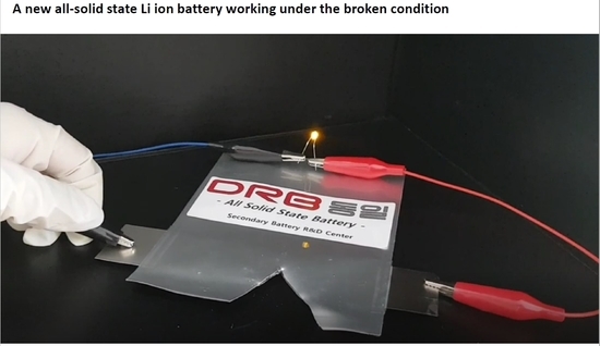
A representative coin cell preparation using the designed HSE-4 and HSC-2 is illustrated in Figure 1a. The slurry is coated on Li metal foil by solution casting. LATP, PEO, LiTFSI and SN are mixed in a designed composition using a centrifugal mixer (Thinky Mixer) resulting in a sticky white HSE-4 slurry. LMO and LCO are mixed with PEO and SN, resulting in HSC-2. The HSC-2 is coated on Al foil, followed by HSE-4 slurry casting. The Li metal anode and the designed cathode plates are bonded by heating HSE sides to form a layered structure of a coin cell. In addition, this process is scaled-up for a pouch cell (5 × 10 cm2) in which copper foil is additionally employed outside of the Li metal plate for physical protection (Figure 1b). The designed all-solid-state lithium pouch battery is successfully working in spite of its breakage without any leakage and short-circuits (Supporting Information, Movie S1).
3.2. Structure of the All-Solid-State Battery System
The simplified battery sample is prepared to investigate the performance of HSE and HSC, which are casted and dried on a layered structure stacked from Al foil, cathode (HSC-2) and electrolyte (HSE-4) layers without anode Li metal and protective Cu foil layers. A representative scanning electron microscopy (SEM) image of each layer is shown in a cross-sectional side-view (Figure 2a) and in a top-view (Figure 2b). In the cross-sectional image, the size of particulates in HSC layer (below the dotted-line in the picture) is smaller compared with that in the HSE layer; this is caused by the relatively small size of the LCO and LMO particles (Figure 2d). The images of pure LATP powder are compared in Figure 2c. The top-view images of the designed battery system (Figure 2b) are similar to those of the LATP powder pellet (Figure 2c). For all the systems, the inter-particulate spaces are effectively filled with PEO binding. The SEM images confirm effective physical contact of ion-conducting PEO and solid LATP in the designed HSE layer without phase separation, which is crucial for effective ionic conductivity of a battery. Figure 2b depicts the reticulated PEO connects LATP particles forming ion-conducting pathways, which can decrease boundary resistance in the solid LATP electrolyte. All of these morphologies are advantageous for the increase in the bulk ionic conductivity [47,48,49].
3.3. Conductivity of the Designed Systems
The total resistance is evaluated by ionic conductivity based on the electrochemical impedance spectroscopy (EIS) (Table 1). Using the measured resistance and following relation, ionic conductivity (σ, S/cm) of the designed HSE and HSC is evaluated,
where l is the thickness (cm) of the HSE, A is the area (cm2) of the sample, S is the total resistance (Ω) obtained from EIS spectra. The ionic conductivity of the designed HSE shows almost three orders higher (~10−4 S/cm) than that of pure PEO (10−6~10−8 S/cm) [50] at the same EO to Li (8:1). This result confirms the contribution of high ionic conductivity of LATP embedded in the ion-conducting PEO by the reduced bulk and boundary resistance. Due to characteristic temperature-dependence, ionic conductivity at 55 °C is about 10 times higher than that at 23 °C in every sample. The composite system consisting of LiTFSI shows similar ionic conductivity as that using LiPF6. By adding SN, ionic conductivities (2.0 × 10⁻⁴ S/cm @ 23 °C & 1.6 × 10⁻³ S/cm @ 55 °C) are enhanced compared with those (1.5 × 10⁻⁴ S/cm @ 23 °C & 1.4 × 10⁻³ S/cm @ 55 °C) without SN introduction by increased segmental mobility of PEO in HSE [40,51]. In particular, the increase in ionic conductivity by SN introduction is prominent at room temperature.
3.4. Solid Electrolyte Interface (SEI)
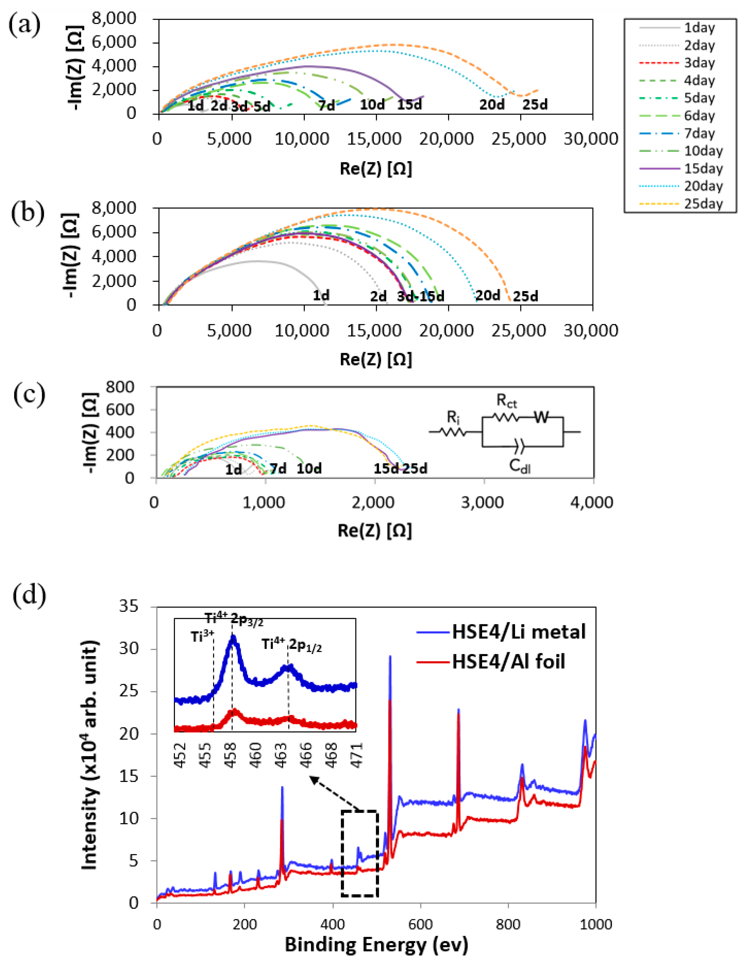
Even with several controversies the LATP and Li metal is reported to react immediately upon a physical contact and forms an unfavorable solid electrolyte interface (SEI) layer on the Li metal surface [52,53]. Through this unfavorable phenomenon Li ion movement is reduced, thus decreasing the ionic conductivity. However, this can be suppressed by surface modification using PEO coating. The role of PEO in HSE is, at the same context, surrounding each LATP particle to protect the Li metal surface. The efficacy of the designed HSE on Li metal anode is investigated by measuring the AC impedance (Figure 3c). The chemical reactions of the designed model cells symmetrically composed of Li/LATP pellet/Li and Li/HSE/Li are evaluated for 25 days. The LATP pellet was made without sintering LATP powder after pressing. The experiment is performed to analyze the chemical reaction at the interface of LATP, HSE-1(PEO), HSE-4 and Li metal. Thus, the initial interfacial resistance of Li/LATP/Li symmetric cell was measured to be high. Among them, selected results of Li/LATP/Li, Li/HSE-1/Li and Li/HSE-4/Li are shown Figure 3a–c. The increase in the interfacial resistance has been observed in the system of LATP/Li metal [54] and PEO/Li metal by the characteristic chemical reactions [42].
The interfacial resistance of the symmetric cells designed as Li/LATP/Li and Li/HSE-1/Li continuously increase the interfacial resistance for 25 days. However, the resistance of the Li/HSE-4/Li cell is almost similar at a low value for all 25 days (Figure 3c). The result suggests that the reaction of HSE-4 on Li metal is far more effective than that of LATP. An equivalent circuit to describe the observed AC impedance spectra is shown in the inset of Figure 3c, which represents a hybrid solid electrolyte sandwiched between two blocking electrodes. In this equivalent circuit, Rct is the bulk resistance of the solid electrolyte, Cdl (constant phase element) denotes the bulk capacitance of the hybrid solid electrolyte, and Ri corresponds to the double layer capacitance at the electrode/electrolyte interface. Constant phase elements rather than capacitors were employed to describe non-idealities in AC impedance responses. The experimental data were fitted using the Randles equivalent circuit. Indeed, the AC impedance of a lithium metal symmetric cell is composed of the resistance at the electrolyte/electrode interface and the Ohmic resistance of the electrolyte itself.
In order to evaluate the impedance aforementioned result, X-ray photoelectron spectroscopy (XPS) measurements of the HSE samples are performed before and after the reaction with Li metals for 25 days (Figure 3d). For this, Ti peaks of HSE-4 pasted on Li metal after aging procedures for 25 days (blue line) are compared with HSE-4 on Al foil, with the physical substrate (red line) employed as a standard. Doublet peaks consist of Ti 2p1/2 and Ti 2p3/2: two strong Ti4+ peaks, i.e., 2p1/2 (Ti4+, 464.6 eV) and 2p3/2 oxide (Ti4+, 458.8 eV), two Ti3+ peaks (457 eV and 463.1 eV) [55].
Even with physical contact of HSE-4 with Li metal, the binding energy of two samples in this study is same. The resulting XPS has no difference where the Ti 2p1/2 and Ti 2p3/2 remain at the same energy position, indicating there is no Ti reduction (from Ti4+ to Ti3+) [54].
3.5. Electrochemical Stability
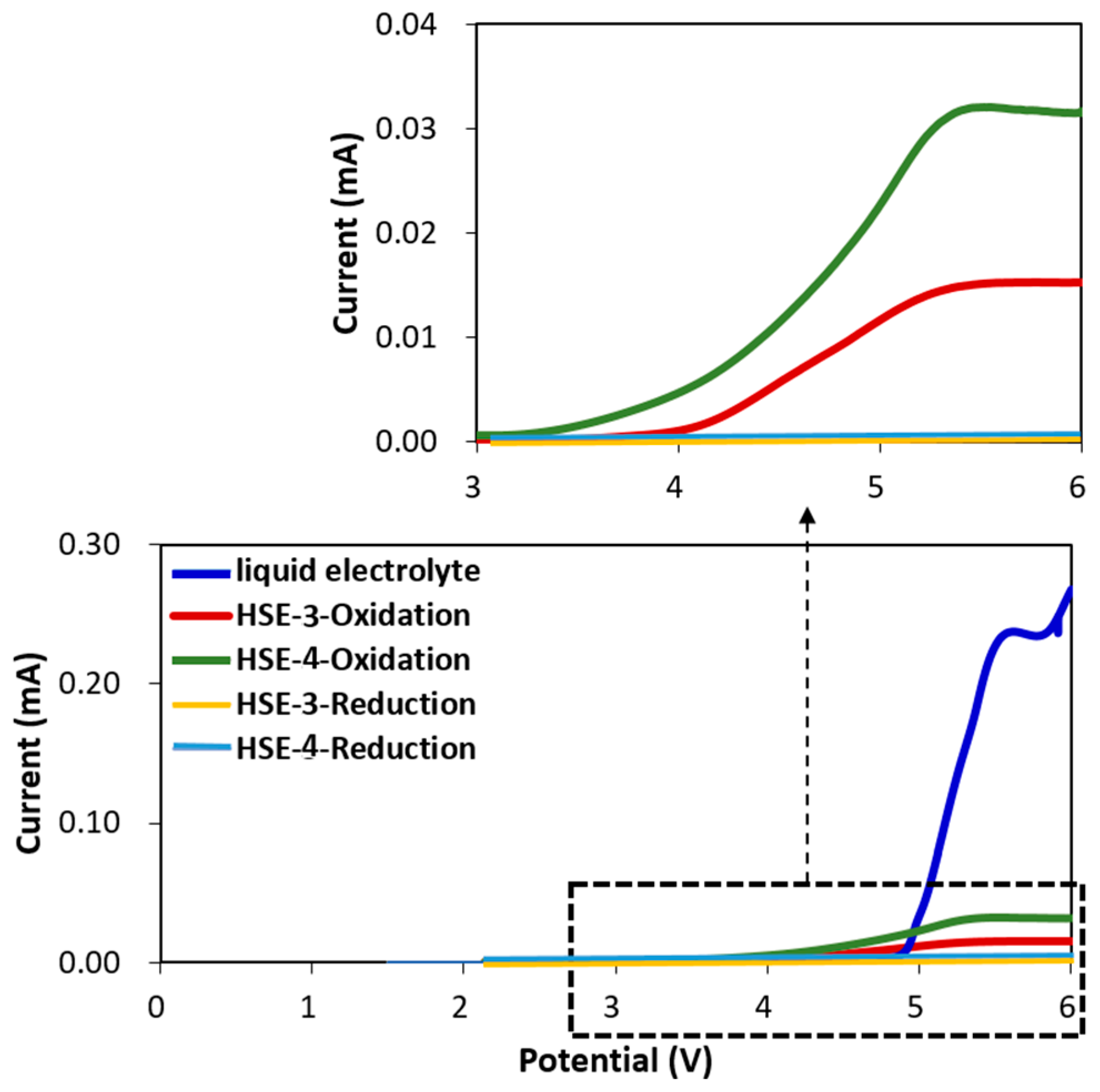
To investigate the electrochemical stability of each electrolyte layer, linear sweep voltammetry (LSV) was measured from 1.5 to 6 V for both reduction and oxidation procedures (Figure 4). The oxidative stability is measured from the open current voltage (OCV) by sweeping up the voltage, while the reduction is measured by sweeping down the voltage. In Figure 4, the voltage was swept from ~2.2 V up to 6 V and then down again to 2.2 V. Both electrolytes HSE-3 and HSE-4 clearly show an onset of oxidation around 4 and 3.4 V, respectively. After going up to 6 V, the electrolyte will be partially or completely decomposed. During the sweeping down from that stage, the reductive stability was measured in a separate experiment: 1.2 mol L−1 LiPF6 in a 15:50:35 (in volume ratio) mixture of ethylene carbonate (EC) and ethyl methyl carbonate (EMC) and dimethyl carbonate (DMC) as the liquid electrolyte used as a standard contrast is oxidized at 4.8 V indicated by the sudden increase in the current (blue line). HSE (HSE-3) and HSE+SN (HSE-4) are also oxidized even if the absolute current intensity is relatively lower than that of liquid electrolyte. This electrochemical investigation of the designed cells indicates protective film formation on the cathode surface in the first cycle which works as a solid electrolyte interphase (SEI) in liquid electrolytes. On the other hand, during the reduction procedure of both HSE-3 and HSE-4, the current is very low without noticeable peak in all voltage regions observed in this study.
3.6. Property of the Designed Electrolytes
Due to inherent high boundary resistance, LATP hardly generates high ionic conductivity. A value of ca. 3.4 × 10⁻³ S/cm at 293 K, is among the highest conductivities reported for LATP-based systems [56,57,58]. To overcome this disadvantage, PEO is employed in this study. The structure of the PEO-incorporated system prepared on Al foil is investigated using X-ray powder diffraction (XRD) in Figure 5a. The XRD patterns of LATP-incorporated systems are almost similar. XRD patterns of HSE films exhibit lower intensity by the polymer incorporation without peak broadening. With the SN incorporation, XRD peak intensity becomes far lower, indicating the dilution of the whole system. Nonetheless the lattice structure is effectively maintained.
The ionic conductivity and thermal characteristics are modified according to the molecular weight of the PEO, which changes from 1 × 10⁵, 3 × 10⁵ to 6 × 10⁵ in this study. The segmental mobility of PEO is investigated using differential scanning calorimetry (DSC) (Figure 5b). With the increase of PEO molecular weight, the peak temperature increases from 65.741 °C (PEO Mw = 1 × 10⁵), 67.663 °C (PEO Mw = 3 × 10⁵) and 68.157 °C (PEO Mw = 6 × 10⁵). In addition, the magnitude of the heat density decreases from 178.31 J/g, 172.41 J/g to 170.87 J/g. However, the designed HSE systems with LATP and SN do not generate characteristic peaks at the given condition in Figure 5c. This indicates that incorporation of LATP and SN effectively broadens the amorphous state to the wide temperature ranges, increasing the ionic conductivity under that condition. The DSC result of the system consisting of LiTFSI has been verified to become amorphous when the ratio of the [EO]/[Li] is higher than ten [59]. In this study, the system consisted of LiTFSI with the ratio [EO]/[Li] = 8 exhibits an amorphous phase with the help of SN introduction. Based on this ionic conductivity result, the system with higher molecular weight PEO Mw = 6 × 10⁵ is selected to obtain the enhanced mechanical property for the design of HSE, while lower molecular weight PEO Mw = 3 × 10⁵ is employed for better mixing efficacy to design the cathode electrode.
3.7. Capacity and 1st Coulomb Efficiency of the Designed Coin Cells
Figure 6a shows specific capacity-voltage curves of the first charge-discharge cycles of the selected model cell systems. The 1st cyclic profiles of the LCO-LMO/HSE/Li system for each designed HSC-1/HSE-2/Li, HSC-1/HSE-3/Li and HSC-1/HSE-4/Li and HSC-2/HSE-4/Li are compared at 55 °C. The HSC-1/HSE-2/Li curve has more polarization loss compared to other curves. Further, the plateau region is quite broader for three other cases compared to the discharge curve of HSC-1/HSE-2/Li in terms of the slope nature. Although the difference is small in all the systems, the result of HSC-1/HSE-2/Li shows slight a disadvantage compared to the three other systems. Electrochemical Impedance Spectroscopy (EIS) results at 55 °C (Figure 6b) and room temperature (Figure 6c) are shown. LiPF6 is generally used for liquid electrolytes, while LiClO4 and LiTFSI are favorably employed for solid electrolyte systems. The ionic conductivity of the designed HSE is not so different (Table 1) but the resistance and charge-discharge efficacy in the designed Li ion cell are very different. LiPF6 (HSC-1/HSE-2/Li) and LiTFSI (HSC-1/HSE-3/Li, HSC-1/HSE-4/Li& HSC-2/HSE-4/Li) are used with PEO in this study, in which the physical properties of HSC-1/HSE-2/Li are different from other three systems.
However, for LiPF6 (HSC-1/HSE-2/Li for this study) and LiTFSI incorporated systems (HSC-1/HSE-4/Li for this study), the resistance of the system in actual Li ion cell state doubles at 55 °C and LiPF6 (HSC-1/HSE-2/Li in this study) and in LiTFSI incorporated systems (HSC-1/HSE-3/Li for this study); the resistance of the system in the actual Li ion cell state increases four-fold compared with that at room temperature. In the Li ion cell state, the re-crystallization kinetics of PEO has been effectively slowed by the use of Li ions and bulky anions [60]. The moisture generated by the electrode-cooling, decomposes LiPF6 into PF5, leading to the resistance increase by the interaction between PEO and SEI [61]. Through this effect, in addition to overcharging, the constant voltage region becomes broader during the charging process while capacity decreases during the discharging procedure. When moisture-resistant LiTFSI or LiTFSI+SN are used, aforementioned phenomena are reduced and capacity can be increased. In the system composed of LiTFSI+SN (HSE-4), SN promotes the Li ion dissolution, thus capacity increases far higher than that of LiTFSI-only (HSE-3). The charging-discharging process occurring at room temperature also shows similar results for the three systems while the HSC-1/HSE-2/Li composed of LiPF6 exhibits a dramatic difference. This result indicates that the moisture formation after the cooling procedure turns the LiPF6 into PF6 gas and SEI in PEO, where SEI decreases the efficiency of the battery function significantly.
The Li ion transport resistance in the HSE system is determined by its through-plane resistance instead of the ionic conductivity. The actual Li ion transport resistance may increase with increasing HSE thickness [62]. The designed HSEs in this study are the same thickness. Therefore, the higher conductivity of HSE+SN(HSE-4) ensures excellent Li ion transport performance. This is due to higher ionic conductivity of HSE-4 than HSE-3 and HSE-4 (Table 1), and the reduced resistance of a designed system even with the same thickness (Figure 6c).
Figure 7a displays 1st charge-discharge profiles of the LCO-LMO/electrolyte/Li metal systems of selected HSC-1/HSE-4/Li and HSC-2/HSE-4/Li (both are based on LiTFSI+SN composition) at room temperature. This indicates that SN addition boosts the battery function compared with the cells employing LiPF6 (HSC-1/HSE-2/Li) and LiTFSI-only (HSC-1/HSE-3/Li), which are not working effectively at room temperature. The difference is clearer by the C-rate performance at 55 °C (Figure 7b). The C-rate values of each region are on the graph: 0.05 C, 0.1 C, 0.2 C, 0.5 C, and 0.05 C. At the 1st charging procedure, the capacity of each cell is 111.4 mAh/g (HSE-2), 118.5 mAh/g (HSE-3), 118.9 mAh/g (HSE-4), and 123.4 mAh/g (HSC-2), while at the discharging procedure, it is 96.2 mAh/g, 97.6 mAh/g, 99.9 mAh/g, and 102.7 mAh/g, respectively. At the initial formation, Coulombic efficiency was 86.4%, 82.3%, 84.0%, and 83.2%, respectively, based on the ratio of discharged capacity to charged capacity. In addition, their Coulombic efficiency increases continuously and is stabilized. After the initial cyclic repetition, the overall cyclic repetition over the 99% is maintained. After 20 cycles, it is also maintained by the charging-recharging at 0.05 C.
4. Discussion and Conclusions
In this study, hybrid solid electrolytes (HSEs) composed of LATP, PEO and SN are successfully designed without protection layer introduction. The solid electrolyte, LATP interaction with Li ion, promotes the reduction of Ti4+ into Ti3+. The LATP shows ion conductivity of 3 × 10⁻³ S/cm under the state of Ti4+ but it becomes far lower under the state of Ti3+ due to structural deformation affecting Li ion movement [11]. We observed no reduction of Ti4+ into Ti3 in the designed system which is investigated by Electrochemical Impedance Spectroscopy (EIS) and X-ray photoelectron spectroscopy (XPS).
In addition to the new hybrid solid electrolyte (HSE), new hybrid solid cathodes (HSCs) are designed and investigated, composed of LATP, PEO, LiTFSi and SN. Typically employed for mass-production, slurry casting methods are utilized followed by lamination to reduce contact resistance. In addition, during the dynamic charge-discharge procedure of the designed Li ion cells, the effects of internal resistance on the charge-discharge procedure and C-rate changes are investigated. The interfacial resistance of HSE-4/Li metal symmetric cell is greatly improved compared with the LATP/Li metal symmetric cell (Figure 3). This suggests that the solution casting process and lamination introduced in this study lower the contact resistance between the Li metal and HSE-4. With good cycling stability, the designed cell also exhibits reasonable interfacial contact efficiency with electrode.
We suggest the new electrolyte system is advantageously utilized in all solid-state Li batteries. Even without any protection layer, the designed system shows no reduction of Ti. This study contributes to a new design technology and further possible mass-production of all solid-state Li batteries in more economical and effective ways.
Supplementary Files
Supplementary File 1Author Contributions
Data curation, S.C. and S.A.; Formal analysis, S.C. and S.A.; Funding acquisition, S.C.; Writing—original draft, S.C. and S.A.; Writing—review & editing, S.K. (Shinho Kim), W.K., S.K. (Seok Kim) and S.A.
Acknowledgments
This research was supported by the Industrial Fundamental Technology Development Program (10052745, Development of the nano-sized (100 nm) manganese ceramic material for high voltage pseudo-capacitor) funded by the Ministry of Trade, Industry and Energy (MOTIE) of Korea.
Conflicts of Interest
The authors declare no competing interests.
References
- Nazri, A. Lithium Batteries Science and Technology; Kluwer Academic Publishers: New York, NY, USA, 2009. [Google Scholar]
- Wang, Q.; Ping, P.; Zhao, X.; Chu, G.; Sun, J.; Chen, C. Thermal runaway caused fire and explosion of lithium ion battery. J. Power Sources 2012, 208, 210–224. [Google Scholar] [CrossRef]
- Santhanagopalan, S.; Ramadass, P.; Zhang, J. Analysis of internal short-circuit in a lithium ion cell. J. Power Sources 2009, 194, 550–557. [Google Scholar] [CrossRef]
- Armand, M.; Tarascon, J.M. Building better batteries. Nature 2008, 451, 652–657. [Google Scholar] [CrossRef] [PubMed]
- Wakihara, M.; Kadoma, Y.; Kumagai, N.; Mita, H.; Araki, R.; Ozawa, K.; Ozawa, Y. Development of nonflammable lithium ion battery using a new all-solid polymer electrolyte. J. Solid State Electrochem. 2012, 16, 847–855. [Google Scholar] [CrossRef]
- Goodenough, J.B. Ceramic solid electrolytes. Solid State Ion. 1997, 94, 17–25. [Google Scholar] [CrossRef]
- Knauth, P. Inorganic solid Li ion conductors: An overview. Solid State Ion. 2009, 180, 911–916. [Google Scholar] [CrossRef]
- Xu, K. Nanoqueous Liquid Electrolytes for Lithium-Based Rechargeable Batteries. Chem. Rev. 2004, 104, 4303–4418. [Google Scholar] [CrossRef]
- Goodenough, J.B.; Kim, Y. Challenges for rechargeable batteries. J. Power Sources 2011, 196, 6688–6694. [Google Scholar] [CrossRef]
- Fergus, W.J. Ceramic and polymeric solid electrolytes for lithium-ion batteries. J. Power Sources 2010, 195, 4554–4569. [Google Scholar] [CrossRef]
- Tanaka, K. Lithium ion conduction in LiTi2(PO4)3. J. Electrochem. Acta 2014, 133, 529–538. [Google Scholar]
- Park, C.G. Lithium bis(fluorosulfonyl)imide/poly(ethylene oxide)polymer electrolyte. In Principles and Applications of Lithium Secondary Batteries; Hongpub: Seoul, Korea, 2010; pp. 327–328. [Google Scholar]
- Tong, Y.; Lyu, H.; Xu, Y.; Bishnu, P.T.; Li, P.; Xiao, G.S.; Sheng, D. All-solid-state interpenetrating network polymer electrolytes for long cycle life of lithium metal batteries. J. Mater. Chem. A 2018, 6, 14847–14855. [Google Scholar] [CrossRef]
- Zeng, X.X.; Yin, Y.X.; Li, N.W.; Du, W.C.; Guo, Y.G.; Wan, L.J. Reshaping Lithium Plating/Stripping Behavior via Bifunctional Electrolyte for Room Temperature Solid Li Metal Batteries. J. Am. Chem. Soc. 2016, 138, 15825–15828. [Google Scholar] [CrossRef] [PubMed]
- Li, J.; Ma, C.; Chi, M.; Liang, C.; Dudney, N. Solid electrolyte: The key for high-voltage lithium batteries. Adv. Energy Mater. 2015, 5, 1401408. [Google Scholar] [CrossRef]
- Bachman, J.C.L.; Muy, S.; Grimaud, A.; Chang, H.; Pour, N. Inorganic solid-state electrolytes for lithium batteries: Mechanisms and properties governing ion conduction. Chem. Rev. 2015, 116, 140–162. [Google Scholar] [CrossRef] [PubMed]
- Xiayin, Y. All-solid-state lithium batteries with inorganic solid electrolytes: Review of fundamental science. Chin. Phys. 2016, B25, 018802. [Google Scholar]
- Goodenough, J.B.; Singh, P. Review—Solid electrolytes in rechargeable electrochemical cells. J. Electrochem. Soc. 2015, 162, A2387–A2392. [Google Scholar] [CrossRef]
- Janek, J.; Zeier, W.G. A solid future for battery development. Nat. Energy 2016, 1, 16141. [Google Scholar] [CrossRef]
- Porcarelli, L.; Shaplov, A.S.; Salsamendi, M.; Nair, J.R.; Vygodskii, Y.S.; Mecerreyes, D.; Gerbaldi, C. Single-Ion Block Copoly(ionic liquid)s as Electrolytes for All-Solid State Lithium Batteries. ACS Appl. Mater. Interfaces 2016, 8, 10350–10359. [Google Scholar] [CrossRef]
- Porcarelli, L.; Aboudzadeh, M.; Rubatat, L.; Nair, J.R.; Shaplovde, A.S.; Gerbaldib, C.; Mecerreyesa, D. Single-ion triblock copolymer electrolytes based on poly(ethylene oxide) and methacrylic sulfonamide blocks for lithium metal batteries. J. Power Sources 2017, 364, 191–199. [Google Scholar] [CrossRef]
- Porcarelli, L.; Manojkumar, K.; Sardon, H.; Llorente, O.; Shaplovde, A.S.; Gerbaldi, C.; Vijayakrishna, K.; Mecerreyes, D. Single ion conducting polymer electrolytes based on versatile polyurethanes. Electrochim. Acta 2017, 241, 526–534. [Google Scholar] [CrossRef]
- Porcarelli, L.; Gerbaldi, C.; Bella, F.; Nair, J.R. Super soft all-ethylene oxide polymer electrolyte for safe all-solid lithium batteries. Sci. Rep. 2016, 6, 19892. [Google Scholar] [CrossRef] [PubMed]
- MacCallum, J. Polymer Electrolyte Reviews-1; Elsevier Applied Science: London, UK; New York, NY, USA, 1987. [Google Scholar]
- Bailey, F.E., Jr.; Koleske, J.V. Poly(ethylene oxide); Academic Press: New York, NY, USA, 1976. [Google Scholar]
- Wright, P.V. Electrical conductivity in ionic complexes of poly(ethylene oxide). Polym. Int. 1975, 7, 319–327. [Google Scholar] [CrossRef]
- Fenton, D.E. Complexes of alkali metal ions with poly(ethylene oxide). Polymer 1973, 14, 589. [Google Scholar] [CrossRef]
- Armmd, M.B. Polymer solid electrolytes—An overview. Solid State Ion. 1983, 9–10, 745–754. [Google Scholar] [CrossRef]
- Ryu, S.W.; Trapa, P.E.; Olugebefola, S.C.; Gonzalez-Leon, J.A.; Sadoway, D.R.; Mayes, A.M. Effect of counter ion placement on conductivity in single-ion conducting block copolymer electrolytes. J. Electrochem. Soc. 2005, 152, A158–A163. [Google Scholar] [CrossRef]
- Kang, W.C.; Park, H.G.; Kim, K.C.; Ryu, S.W. Synthesis and electrochemical properties of lithium methacrylate-based self-doped gel polymer electrolytes. Electrochim. Acta 2009, 54, 4540–4544. [Google Scholar] [CrossRef]
- Bruce, P.G.; Vincent, C.A. Steady state current flow in solid binary electrolyte cells. J. Electroanal. Chem. Interfacial Electrochemchem. 1987, 225, 1–17. [Google Scholar] [CrossRef]
- Kroka, F.; Dygasa, J.R.; Misztal-Faraja, B.; Florjańczyk, Z.; Bzducha, W. Impedance and polarization studies of new lithium polyelectrolyte gels. J. Power Sources 1999, 81, 766–771. [Google Scholar] [CrossRef]
- Stramare, S.; Weppner, W. Structure and conductivity of B-site substituted (Li,La)TiO3. Mater. Sci. Eng. 2004, B113, 85–90. [Google Scholar] [CrossRef]
- Murugan, R.; Thangadurai, V.; Weppner, W. Fast Lithium Ion Conduction in Garnet-Type Li7La3Zr2O12. Angew. Chem. 2007, 46, 7778–7781. [Google Scholar] [CrossRef]
- Hanc, E.Z.; Molenda, J. Fast Lithium Ion Conduction in Garnet-Type Li7La3Zr2O12. Solid State Ion. 2014, 262, 617–621. [Google Scholar] [CrossRef]
- Aono, H.; Sugimoto, E.; Sadaoka, Y.; Imanaka, N.; Adachi, G.J. Ionic Conductivity of Solid Electrolytes Based on Lithium Titanium Phosphate. Electrochem. Soc. 1990, 137, 1023–1027. [Google Scholar] [CrossRef]
- Kato, Y. Discharge Performance of All-Solid-State Battery Using a Lithium Superionic Conductor Li10 GeP2S12. Electrochemtry 2012, 10, 749–751. [Google Scholar] [CrossRef]
- Wang, C.; Yang, Y.; Liu, X.; Zhong, H.; Xu, H.; Xu, Z.; Shao, H. Suppression of Lithium Dendrite Formation by Using LAGP-PEO (LiTFSI) Composite Solid Electrolyte and Lithium Metal Anode Modified by PEO (LiTFSI) in All-Solid-State Lithium Batteries. ACS Appl. Mater. Interfaces 2017, 9, 13694–13702. [Google Scholar] [CrossRef] [PubMed]
- Han, X.; Gong, Y.; Fu, K.; He, X.; Hitz, G.T.; Pearse, A.; Liu, B.; Wang, H.; Rubloff, G.; Mo, Y.; et al. Negating interfacial impedance in garnet-based solid-state Li metal batteries. Nat. Mater. 2017, 16, 572–579. [Google Scholar] [CrossRef] [PubMed]
- Jung, Y.C.; Lee, S.M.; Choi, J.H.; Jang, S.S.; Kim, D.W. All Solid-State Lithium Batteries Assembled with Hybrid Solid Electrolytes. J. Electrochem. Soc. 2015, 162, A704–A710. [Google Scholar] [CrossRef]
- Liu, W.; Milcarek, R.J.; Falkenstein-Smith, R.L.; Ahn, J. Interfacial Impedance Studies of Multilayer Structured Electrolyte Fabricated With Solvent-Casted PEO10–LiN(CF3SO2)2 and Ceramic Li1.3Al0.3Ti1.7(PO4)3 and Its Application in All-Solid-State Lithium Ion Batteries. Electrochem. Energy Convers. Storage 2016, 13, 021008. [Google Scholar] [CrossRef]
- Zhao, Y.; Wu, C.; Peng, G.; Chen, X.; Yao, X.; Bai, Y.; Wu, F.; Chen, S.; Xu, X. A new solid polymer electrolyte incorporating Li10GeP2S12 into a polyethylene oxide matrix for all-solid-state lithium batteries. J. Power Sources 2016, 301, 47–53. [Google Scholar] [CrossRef]
- Chen, B.; Huang, Z.; Chen, Z.; Zhao, Y.; Xu, Q.; Peng, L.; Chen, S.; Xu, X. A new composite solid electrolyte PEO/Li10GeP2S12/SN for all-solid-state lithium battery. Electrochim. Acta 2016, 210, 905–914. [Google Scholar] [CrossRef]
- Long, S.; Macfarlane, D.R.; Forsyth, M. Fast ion conduction in molecular plastic crystals. Solid State Ion. 2003, 161, 105–112. [Google Scholar] [CrossRef]
- Alarco, P.J.; Abu-Lebdeh, Y.; Armand, M. Highly conductive, organic plastic crystals based on pyrazolium imides. Solid State Ion. 2004, 175, 717–720. [Google Scholar] [CrossRef]
- Ohtomo, T.; Hayashi, A.; Tatsumisago, M.; Kawamoto, K. Suppression of H2S gas generation from the 75Li2S center dot 25P2S5 glass electrolyte by additives. J. Mater. Sci. 2013, 48, 4137–4142. [Google Scholar] [CrossRef]
- Jung, Y.C.; Park, M.S.; Doh, C.H.; Kim, D.W. Organic-inorganic hybrid solid electrolytes for solid-state lithium cells operating at room temperature. Electrochim. Acta. 2016, 218, 271–277. [Google Scholar] [CrossRef]
- Tatsumisago, M.; Nagao, M.; Hayashi, A. Recent development of sulfide solid electrolytes and interfacial modification for all-solid-state rechargeable lithium batteries. J. Asian Ceram. Soc. 2013, 1, 17–25. [Google Scholar] [CrossRef] [Green Version]
- Kim, J.G.; Son, B.; Mukherjee, S.; Schuppert, N.; Bates, A.; Kwon, O.; Choi, M.J.; Chung, H.Y.; Park, S. A review of lithium and non-lithium based solid state batteries. J. Power Sources 2015, 282, 299–322. [Google Scholar] [CrossRef]
- Golodnitsky, D.; Strauss, E.; Peled, E.; Greenbaum, S. Review—On Order and Disorder in Polymer Electrolytes. J. Electrochem. Soc. 2015, 162, A2551–A2566. [Google Scholar] [CrossRef] [Green Version]
- Kim, S.K.; Jung, Y.C.; Kim, D.H.; Shin, W.C.; Ue, M.; Kim, D.W. Lithium-Ion Cells Assembled with Flexible Hybrid Membrane Containing Li+-Conducting Lithium Aluminum Germanium Phosphate. J. Electrochem. Soc. 2016, 163, A974–A980. [Google Scholar] [CrossRef]
- Camacho-Forero, L.E.; Smith, S.; Bertolini, T.W.; Balbuena, P.B. Reactivity at the Lithium–Metal Anode Surface of Lithium–Sulfur Batteries. J. Phys. Chem. C 2015, 119, 26828–26839. [Google Scholar] [CrossRef]
- Lin, D.; Liu, Y.; Cui, Y. Reviving the lithium metal anode for high-energy batteries. Nat. Nanotechnol. 2017, 12, 194–206. [Google Scholar] [CrossRef]
- Hartmann, P.; Leichtweiss, T.; Busche, M.R.; Schneider, M.; Reich, M.; Sann, J.; Adelhelm, P.; Janek, J. Degradation of NASICON-Type Materials in Contact with Lithium Metal: Formation of Mixed Conducting Interphases (MCI) on Solid Electrolytes. J. Phys. Chem. 2013, C117, 21064–21074. [Google Scholar] [CrossRef]
- Fu, Y.; Du, H.; Zhang, S.; Huang, W. XPS characterization of surface and interfacial structure ofsputtered TiNi films on Si substrate. Mater. Sci. Eng. 2005, A403, 25–31. [Google Scholar] [CrossRef]
- Marinado, T.; Hahlin, M.; Jiang, X.; Quintana, M.; Johanesson, E.M.J.; Gabrielsson, E.; Plogmaker, S.; Hagberg, D.P.; Boschloo, G.; Zakeeruddin, S.M.; et al. Surface Molecular Quantification and Photoelectrochemical Characterization of Mixed Organic Dye and Coadsorbent Layers on TiO2 for Dye-Sensitized Solar Cells. J. Phys. Chem. 2010, C114, 11903–11910. [Google Scholar] [CrossRef]
- Campbell, J.L.; Rapp, T. Widths of the atomic K–N7 levels. In Atomic Data and Nuclear Data Tables; Elsevier: New York, NY, USA, 2001; Volume 77, pp. 1–56. [Google Scholar] [CrossRef]
- Takahashi, K.; Ohmura, J.; Im, D.; Lee, D.J.; Zhang, T.; Imanishi, N.; Hirano, A.; Phillipps, M.B.; Takeda, Y.; Yamamoto, O. A Super High Lithium Ion Conducting Solid Electrolyte of Grain Boundary Modified Li1.4Ti1.6Al0.4(PO4)3. J. Electrochem. Soc. 2012, 159, A342–A348. [Google Scholar] [CrossRef]
- Geiculescu, O.E.; Rajagopal, R.; Creager, S.E.; DesMarteau, D.D.; Zhang, X.; Fedkiw, P. Transport Properties of Solid Polymer Electrolytes Prepared from Oligomeric Fluorosulfonimide Lithium Salts Dissolved in High Molecular Weight Poly(ethylene oxide). J. Phys. Chem. B 2006, 110, 23130–23135. [Google Scholar] [CrossRef] [PubMed]
- Vallee, A.; Besner, S.; PrudHomme, J. Comparative study of poly(ethylene oxide) electrolytes made with LiN(CF3SO2)2, LiCF3SO3 and LiClO4: Thermal properties and conductivity behavior. Electrochem. Acta 1992, 37, 1579–1583. [Google Scholar] [CrossRef]
- Sloop, S.E.; Kerr, J.B.; Kinoshita, K. The role of Li-ion battery electrolyte reactivity in performance decline and self-discharge. J. Power Sources 2003, 119, 330–337. [Google Scholar] [CrossRef]
- Xiang, Y.; Wang, Z.; Qiu, W.; Guo, Z.; Liu, D.; Qu, D.; Xie, Z.; Tang, H.; Li, J. Interfacing soluble polysulfides with a SnO2 functionalized separator: An efficient approach for improving performance of Li-S battery. J. Memb. Sci. 2018, 563, 380–387. [Google Scholar] [CrossRef]
Figure 1.
(a) Preparation of all-solid-state coin-cell using the designed HSE and HSC in this study. (b) Configuration of all-solid-state pouch cell at a 5 × 10 cm2 scale (left scheme) and its operation (right picture).
Figure 1.
(a) Preparation of all-solid-state coin-cell using the designed HSE and HSC in this study. (b) Configuration of all-solid-state pouch cell at a 5 × 10 cm2 scale (left scheme) and its operation (right picture).

Figure 2.
SEM images of (a) cross-section and (b) Top view of HSE-4/HSC-2/Al foil on carbon tape. SEM images of (c) LATP powder and (d) LCO and LMO powder. Scale bars in the images.
Figure 2.
SEM images of (a) cross-section and (b) Top view of HSE-4/HSC-2/Al foil on carbon tape. SEM images of (c) LATP powder and (d) LCO and LMO powder. Scale bars in the images.


Figure 3.
Impedance spectra of (a) Li/LATP/Li (b) Li/HSE-1/Li (c) Li/HSE-4/Li symmetric cells during 25 days (d) Ti2p3/2 and Ti2p1/2 photoelectron signals of Ti films (HSE-4) coated on Li metal and Al foil for 25 days.
Figure 3.
Impedance spectra of (a) Li/LATP/Li (b) Li/HSE-1/Li (c) Li/HSE-4/Li symmetric cells during 25 days (d) Ti2p3/2 and Ti2p1/2 photoelectron signals of Ti films (HSE-4) coated on Li metal and Al foil for 25 days.

Figure 4.
Linear sweep voltammetry (LSV) scans of HSE-3 and HSE-4. Pt is employed as a working electrode and Li metal is employed as reference electrodes. Scan rate is at the 1 mV/s.
Figure 4.
Linear sweep voltammetry (LSV) scans of HSE-3 and HSE-4. Pt is employed as a working electrode and Li metal is employed as reference electrodes. Scan rate is at the 1 mV/s.

Figure 5.
(a) XRD Patterns of LATP, HSE-3, HSE-4 (b) DSC of PEO with different molecular weight 1 × 10⁵, 3 × 10⁵ and 6 × 10⁵ (c) DSC of HSE-3 (PEO 3 × 10⁵), HSE-3 (PEO 6 × 10⁵) and HSE-4 (PEO 3 × 10⁵) composed of each PEO.
Figure 5.
(a) XRD Patterns of LATP, HSE-3, HSE-4 (b) DSC of PEO with different molecular weight 1 × 10⁵, 3 × 10⁵ and 6 × 10⁵ (c) DSC of HSE-3 (PEO 3 × 10⁵), HSE-3 (PEO 6 × 10⁵) and HSE-4 (PEO 3 × 10⁵) composed of each PEO.

Figure 6.
(a) 1st charge-discharge profiles of HSC-1/HSE-2/Li, HSC-1/HSE-3/Li, HSC-1/HSE-4/Li and HSC-2/HSE-4/Li at 55 °C. EIS profiles of (b) HSC-1/HSE-2/Li and HSC-1/HSE-4/Li at 55 °C and (c) HSC-1/HSE-2/Li, HSC-1/HSE-3/Li, HSC-1/HSE-4/Li and HSC-2/HSE-4/Li at room temperature.
Figure 6.
(a) 1st charge-discharge profiles of HSC-1/HSE-2/Li, HSC-1/HSE-3/Li, HSC-1/HSE-4/Li and HSC-2/HSE-4/Li at 55 °C. EIS profiles of (b) HSC-1/HSE-2/Li and HSC-1/HSE-4/Li at 55 °C and (c) HSC-1/HSE-2/Li, HSC-1/HSE-3/Li, HSC-1/HSE-4/Li and HSC-2/HSE-4/Li at room temperature.

Figure 7.
(a) 1st charge-discharge profiles of HSC-1/HSE-4/Li cell and HSC-2/HSE-4/Li cell at room temperature. (b) C-rate performance of HSC-1/HSE-2, HSE-3, HSE-4/Li cells and HSC-2/HSE-4/Li cell at 55 °C.
Figure 7.
(a) 1st charge-discharge profiles of HSC-1/HSE-4/Li cell and HSC-2/HSE-4/Li cell at room temperature. (b) C-rate performance of HSC-1/HSE-2, HSE-3, HSE-4/Li cells and HSC-2/HSE-4/Li cell at 55 °C.


Table 1.
Designed hybrid solid electrolyte (HSE) and hybrid solid cathode (HSC) in this study.
| LATP (g) | PEO * (g) | LiPF6 | LiTFSI | SN (g) | LMO+LCO (g) | EO:Li (Mole ratio) | Ion. Con. @23 °C [S/cm] | Ion. Con. @55 °C [S/cm] | ||
|---|---|---|---|---|---|---|---|---|---|---|
| HSE | HSE-1 | - | 100 | ● | - | - | - | 8:1 | 1.7 × 10⁻⁷ | - |
| HSE-2 | 80 | 20 | ● | - | - | - | 8:1 | 1.2 ×1 0−4 | 2.4 × 10⁻³ | |
| HSE-3 | 80 | 20 | - | ● | - | - | 8:1 | 1.5 × 10⁻⁴ | 1.4 × 10⁻³ | |
| HSE-4 | 80 | 20 | - | ● | 5 | - | 8:1 | 2.0 × 10⁻⁴ | 1.6 × 10⁻³ | |
| HSC | HSC-1 | 12.8 | 12.8 | - | ● | - | 30 + 30 | 10:1 | - | - |
| HSC-2 | 12.8 | 12.8 | - | ● | 5 | 30 + 30 | 10:1 | - | - | |
The ionic conductivities of HSE at 23 and 55 °C are shown. * PEO MW = 6 × 10⁵ g·mol−1, is used for HSE-1 to HSE-4, while PEO MW = 3 × 10⁵ g·mol−1 are used for HSC-1 and HSC-2. For the whole battery design, HSE-1 to HSE-4 are combined with HSC-1, but HSC-2 is only combined with HSE-4.
© 2018 by the authors. Licensee MDPI, Basel, Switzerland. This article is an open access article distributed under the terms and conditions of the Creative Commons Attribution (CC BY) license (http://creativecommons.org/licenses/by/4.0/).
Share and Cite
MDPI and ACS Style
Cho, S.; Kim, S.; Kim, W.; Kim, S.; Ahn, S. All-Solid-State Lithium Battery Working without an Additional Separator in a Polymeric Electrolyte. Polymers 2018, 10, 1364. https://doi.org/10.3390/polym10121364
AMA Style
Cho S, Kim S, Kim W, Kim S, Ahn S. All-Solid-State Lithium Battery Working without an Additional Separator in a Polymeric Electrolyte. Polymers. 2018; 10(12):1364. https://doi.org/10.3390/polym10121364
Chicago/Turabian StyleCho, Seonggyu, Shinho Kim, Wonho Kim, Seok Kim, and Sungsook Ahn. 2018. "All-Solid-State Lithium Battery Working without an Additional Separator in a Polymeric Electrolyte" Polymers 10, no. 12: 1364. https://doi.org/10.3390/polym10121364
Note that from the first issue of 2016, this journal uses article numbers instead of page numbers. See further details here.