
A State-of-the-Art Review on Chatter Stability in Machining Thin−Walled Parts

Key Laboratory for Precision and Non-Traditional Machining Technology of the Ministry of Education, Dalian University of Technology, Dalian 116024, China
*
Authors to whom correspondence should be addressed.
Machines 2023, 11(3), 359; https://doi.org/10.3390/machines11030359
Submission received: 15 February 2023
/
Revised: 27 February 2023
/
Accepted: 1 March 2023
/
Published: 6 March 2023
(This article belongs to the Section Advanced Manufacturing)
Abstract
:Thin−walled parts are widely used in many important fields because of performance and structural lightweight requirements. They are critical parts because they usually carry the core functions of high−end equipment. However, their high−performance machining has been facing severe challenges, among which the dynamics problem is one of the most important obstacles. The machining system is easily subjected to chatter due to the weak rigidity of the thin−walled structure and slender cutting tool, which significantly deteriorates the surface quality and reduces the machining efficiency. Extensive studies aiming at eliminating machining chatter have been carried out in the recent decades. This paper systematically reviews previous studies on the identification of system dynamic characteristics, modeling and prediction of chatter stability, and chatter elimination/suppression methods and devices. Finally, existing problems are summarized, and future research is concluded.
1. Introduction
In aviation, aerospace, and the energy industry, thin−walled parts such as aircraft structural parts, impellers, and turbine blades, are gaining more and more important applications. These complex parts usually carry the core functions of high−end equipment and are used in extreme environments with harsh technical requirements [1]. With the improvement of performance and structural lightweight requirements, some difficult−to−cut superalloys such as titanium alloys and nickel−based alloys are increasingly adopted as the workpiece materials; meanwhile, the thin−walled parts are designed into more complex structures with large ratios of wall length to wall thickens (about 50:1–250:1) and height to thickness (about 10:1–50:1) [2]. The double superposition of difficult−to−cut material and thin−walled structure makes the high−performance machining of thin−walled parts challenging due to the combined effect of complicated thermal−mechanical couplings, low structural rigidity, weak damping, time−varying dynamic characteristics, and so on. Machining chatter is the main obstacle hindering the improvement of machining accuracy and efficiency; it produces violent self−excited vibration, creates obvious chatter marks on the finished surface, and in some cases, it even causes the parts to be scrapped or damage to the machine tool.
The research on machining chatter can be traced back to Taylor’s work from 1907 [3]. Through scholars’ long−term study and sustained effort, several basic chatter vibration types are concluded [4], which include frictional chatter, mode coupling chatter, thermomechanical chatter, and regenerative chatter. Among them, regenerative chatter is the most common and dominant type in the machining of thin−walled parts, which arises from an inappropriate phase of overlapping cuts [5]. As a milling case shown in Figure 1, the previous cutting flute left a wavy workpiece surface due to the self−excited vibration of the milling system, the next cutting flute will attack this surface and generate a new wavy workpiece surface. This phenomenon can greatly amplify vibrations, bringing exponentially growing chip thickness, thereby leading to significantly larger forces and vibrations until the cutter is out of contact with the workpiece. Generally, the dynamics of the machining process considering the regenerative effect can be mathematically modeled by delayed differential equations (DDEs) with time delay(s) and time−dependent coefficients [6].
Many scholars have devoted their effort over the past few decades to solving chatter issues, and in−depth research is constantly being reported. Figure 2 depicts the change in the number of publications every two years, from 1999 to 2022. Here, ‘thin−rigidity/low−rigidity/flexible’, ‘Workpiece/part/component/structure’, ‘machining/milling/turning/drilling’, and ‘chatter/stability’ are the keywords and are searched for in the Web of Science. Before 2008, the number of published papers per year was less than 15. However, it began to increase from 2009. Especially after 2017, this amount increased significantly to more than 90. This reflects that researchers are more and more interested in the research of chatter during the machining of thin−walled parts, especially in the last decade. Figure 3 plots the research topics, the plot being created by VOSviewer software.
There are some review articles addressing the chatter issues in different machining processes, which include fundamental modeling of chatter vibrations [8,9], and chatter avoidance/detection/suppression techniques [4,6,10,11]. However, for thin−wall machining, very few review articles have been reported, and relevant critical summaries are still lacking. For this reason, this paper presented a comprehensive review of thin−walled machining dynamics and summarized the research progress in this field. The rest of the paper is organized as follows: Section 2 summarized the identification method of time/position−varying dynamic characteristics for the thin−walled machining system. Section 3 summarizes the developments of chatter stability modeling and analysis methods. Section 4 summarizes the main chatter elimination/suppression methods including machining parameter optimization, variable−geometry chatter suppression cutting tools, spindle speed variation, damping/stiffness enhancement devices, and active chatter control technologies. Section 5 discusses existing problems in the study of thin−walled machining dynamics and offers future research work. Section 6 concludes the paper.
2. Dynamic Characteristics of Thin−Walled Machining System
The dynamic characteristics of the cutting system are the basis for dynamic modeling, chatter prediction, and process control. As for thin−wall machining, the dynamics of the machining system are affected by many factors, such as the workpiece material to be removed, spindle speed, the configuration of the machine tool, and so on. The dynamic characteristics can be investigated from two toughing ends, i.e., the workpiece and the cutter, which directly affect the machining dynamics. Therefore, accurate identification of dynamic characteristics of the thin−walled workpiece and cutting tool is essential.
2.1. Dynamics Identification of In−Process Workpiece
2.1.1. Experimental Modal Analysis
Experimental modal analysis (EMA) is usually based on hammer impact testing and sometimes based on modal shaker testing. For hammer impact testing, the hammer is used to apply impact on a thin−walled part which is instrumented with acceleration sensors or laser vibrometers to collect the excitation responses. The frequency response functions (FRFs) and modal parameters can be extracted and fitted by the data acquisition and processing system. Ismail and Ziaei [12] employed EMA in a chatter stability study for the five−axis machining of the flexible turbine blade. In their study, the measurement position of the acceleration sensor is unchanged, and moving hammer impact tests are conducted on the blade at different cutter positions when the machine is not running. Bravo et al. [13] considered the dynamic variations due to material removal by measuring the in−process FRFs at some intermediate stages of the machining of the walls, as shown in Figure 4. It is inferred from the above literature that using EMA to identify the dynamic characteristics of integral thin−walled parts is time−consuming in the practical machining scene, especially when material removal effects have to be considered. The machine tool needs to be started and stopped frequently, the thin−wall parts must be divided into several regions or machining stages, and the cutter should be kept away from the in−process workpiece during each hammer impact test. However, the advantages of EMA are also obvious. It can easily obtain damping characteristics of machining systems, and its analysis results including natural frequency, damping ratio, and mode shape can be regarded as the true values for complex workpiece structures. Recently, based on EMA, Nikolaev et al. [14] identified workpiece modal parameters during the finish milling of a jet−engine blade by time−domain stochastic subspace identification and studied the influence of material removal on the in−process workpiece damping.
2.1.2. Analytical/Semi−Analytical Methods
In order to quickly extract the in−process dynamic parameters of thin−walled parts, some analytical and semi−analytical methods have been proposed, which usually are based on the beam model, plate, or shell theory. Meshreki et al. [15] considered the continuous change in thickness of thin−walled pocket−shaped aerospace parts during the milling process. They used a two−directional multi−span plate to describe the workpiece analytically and derived trial functions in both the x− and y−directions based on the Rayleigh–Ritz method and the multi−span beam model. Schmitz and Honeycutt [16] presented two analytical solutions for predicting the time−varying dynamics of thin−rib and fixed−free beams. One of the analytical solutions applied the Rayleigh–Ritz method to determine the effective mass and use Castigliano’s theorem to find the stiffness; the other one employed receptance coupling substructure analysis (RCSA) to predict the FRFs in which the receptance is formulated by the Timoshenko beam model. Based on the thin plate theory and mode superposition principle, Song et al. [17] and Fei et al. [18] study the analytical prediction of the time−varying dynamic characteristics during the thin−wall milling process. For the peripheral milling process of thin−walled workpieces with constrained layer damper, Shi et al. [19,20] considered the thin−wall base and constrained layer as Kirchhoff plates (Figure 5). They used Courant’s penalty method to handle the boundary conditions, employed the Rayleigh–Ritz method to proximately express the unknown displacement components, and applied the Lagrange equation to describe the system energy change caused by material removal. Then, the motion−governing equation is solved to obtain the time−varying modal parameters. Based on the Rayleigh–Ritz method and thin shallow shell theory, Liu et al. [21] developed an analytical model to predict the dynamic changes in shell structures. On the other hand, Ahmadi et al. [22] introduced the finite strip method into the modeling of the structural dynamics of thin−walled pocket structures during machining. This semi−analytical method only discretizes the structure in the transverse direction and is therefore computationally efficient.
Although the analytical or semi−analytical methods mentioned above have obvious advantages in the identification efficiency of the in−process dynamic parameters, they are generally only suitable for thin−walled structural parts with relatively regular shapes and have great limitations for curved thin−walled structural parts with complex shapes.
2.1.3. Finite Element Modal Analysis (FEMA)
With the rapid development of computer science, numerical simulation technology has made great progress, and finite element modal analysis (FEMA) is increasingly used in extracting the modal parameters of in−process thin−walled parts. The methods based on FEMA have the advantage of modeling the thin−walled parts with complex geometries and boundary conditions which are often encountered in actual machining [23]. Elbestawi and Sagherian [24] and Altintas et al. [25] were the early authors who identified the workpiece dynamic characteristics using the finite element method during the milling of thin−wall parts. Based on the assumption of small material removal amount, Seguy et al. [26] used a 2D FE model to obtain the dynamic properties of the thin−wall plate, in which the workpiece was meshed by six−node quadratic triangular elements. Mane et al. [27] established a FE model to simulate the speed−dependent dynamic behavior of in high−speed machining system, in which the thin−walled workpiece was also assumed to have a constant geometry and its dynamic behavior changing with respect to the cutter position is considered. By the same assumption, in Refs. [28,29,30,31], the so−called “structural effect” or effective stiffness related to the modal shapes of multiple modes are calculated at arbitrary cutter position of the thin−walled workpiece FE model. It is noted that when material removal becomes significant, the thin−walled workpiece can no longer be regarded as a constant geometry in FE modeling [32,33]. This is because the modal basis will change during the machining, which mainly affects the natural frequencies and produces shifted frequencies.
In view of the workpiece geometry variation caused by material removal, early research based on FEMA usually changes the size in the wall thickness direction to realize material removal simulation, but it is more suitable for thin−walled parts with simple geometries. Re−building and re−meshing the in−process FE model is also a feasible way to identify the in−process workpiece dynamics; however, it is very time−consuming, especially for large−scale thin−walled structures. To improve the identification efficiency, structural dynamic modification techniques for calculating the in−process dynamic parameters of thin−walled parts are given more and more attention. Budark et al. [34,35] proposed a matrix inversion method to estimate the in−process workpiece FRFs, which is based on an initial FE mesh to obtain the initial FRF of the thin−walled workpiece which is modified by using the removed material elements along the tool path in reverse order (see Figure 6). Based on Sherman–Morrison–Woodbury formula, Song et al. proposed a structural dynamic modification method with equal mass [36] or variable mass [37]. They divided the cutting process into multi−cutting steps and regarded material removal of each cutting step as mass and stiffness modification to estimate the corrected FRFs. FEM is recommended in their method to obtain the dynamic characteristics of the unmachined and machined thin−walled structures as the input data. By subtracting the removed material from the thin−walled workpiece to be machined, Yang et al. [38] presented a novel structural dynamic modification strategy in the time domain.
Recently, model order reduction techniques for higher computational efficiency have been developed. Tuysuz and Altintas [39] updated the FRFs of the thin−walled workpiece during machining by using a computationally efficient reduced order dynamic substructuring method, in which the influence of removed material on the workpiece dynamics is canceled by adding a fictitious substructure with the opposite dynamics, and the workpiece FRFs are evaluated in frequency domain. Combined with the perturbation method, this strategy was then extended to the time domain [40], which brought a further improvement in computational efficiency. For the large−scale thin−wall parts machining, Yang et al. [41] proposed efficient local modification strategy, referred to the as decomposition−condensation method, in which the DOF−reduced FE model with respect to the material removal was updated by component mode synthesis and dual modal space structural modification technique. Other recent influential work includes perturbation method [42], wavelet−based method [43], time−varying dynamics updating method [44], generalized equivalent method [45], freedom and mode reduction method [46], interval finite element method [47], and FEM and Taylor series method [48].
The above methods can improve the efficiency of FEMA, but they lack the consideration of possible complex boundary conditions. In the actual machining of thin−walled parts with different shapes, the clamping and positioning forms are various, which may involve a complex fixture–workpiece contact relationship. In addition, the use of coolant or lubricant during machining may also change the dynamic characteristics of the workpiece. FEMA needs to be deeply integrated with operational modal analysis.
2.2. Dynamics Identification of the Slender Cutting Tool
In order to meet the machining requirements of complex thin−walled components, the structure of the cutting tools sometimes needs to be specially designed, such as slender cutters for machining integral impellers. It results in a weaker stiffness of the cutting tool so that the cutter cannot be regarded as a rigid body in dynamic modeling. Hence, it is necessary to identify the dynamic characteristics of the slender cutters, and many important identification methods are discussed in this section.
2.2.1. Modal Impact Testing
Modal impact testing is the classical approach to acquire the frequency response function of the cutting tool [49]. As for the turning or milling process, the structural dynamics can be characterized by the tool point dynamics. In this case, the acceleration sensor is attached to one side of the tool tip point, and the hammer excites the opposite side of the tool tip point, and then the same procedures are conducted in the orthogonal direction of the cutting tool. The typical approach does not involve cross−axis modal testing. Gradisek et al. [50] studied the stability of a two−DOF milling system and found that even a weak cross−axis mode coupling effect is sufficient to affect the cutting stability limit. From extensive modal testing and cutting experiments, Zhang et al. [51] concluded that both regenerative and cross−axis effects exist in the cutting process. By adding the cross−axis modal testing step to the classical methods, the modal parameters containing cross−axis modes can be identified. The above research assumes that the dynamic behavior of the milling system occurs at the tool tip point, while the dynamic characteristics along the cutter axial direction are not considered. Li and Shin [52] proposed a comprehensive simulation model for the end milling process considering the varying dynamic characteristics along the cutter axial direction. Eksioglu et al. [53] presented a dynamic model that considers distributed contact dynamics between the cutter and workpiece. The corresponding modal testing supplements cross−point impact steps along the cutter axis so that the cross−point frequency response functions are obtained. Recently, Jiang et al. [54] proposed a novel modal testing method to identify the modal parameters for constructing a multi−point−contact milling dynamic model (See Figure 7). In their research, triaxial acceleration sensors were used to simultaneously measure the cross−axis and cross−point vibration responses. This method further improved the accuracy of the milling dynamic model with slender cutters. Modal impact testing is the most widely used way in the study of cutting machining dynamics. It has the advantage of accurate identification, but it needs to identify each cutter and handle the combination separately.
The above research shows good performance in obtaining tool dynamics at a certain configuration of the machine tool. Due to the rotation of the spindle and the movement of the driving shaft/joint, the dynamic properties of the cutting tool may be different under the operational state. Using equivalent structures instead of real tools, the acquisition of the FRF at the tool tip point is achieved by impacting the alternative structure in the rotating state of the spindle. Faassen et al. [55] first used a cylindrical bar to replace a tool clamped on a holder and to excite the equivalent tool under the rotation state of the spindle. The FRF of the spindle part was obtained by testing the displacement vibration with a non−contact laser sensor, and then the FRF of the tool part was measured separately. However, the above methods require impacting equivalent tools when the spindle is rotating, which is difficult to achieve impact operation when the spindle speed is high. For non−contact excitation devices, Rantatalo et al. [56] adopted electromagnetic excitation and eddy current displacement sensors to test the vibration response for acquiring dynamic properties of the rotating spindle. Similarly, Tatar et al. [57,58] applied an active magnetic excitation method to excite the spindle and used a laser Doppler vibration displacement sensor to measure the response. The dynamics of the milling spindle and other key components were obtained during the machining process. Although the non−contact excitation device overcomes the disadvantage of impacting spindle rotation, the excitation device installed on the spindle may affect the system structure resulting in changes to its dynamics. To avoid the influence of excitation devices, the vibration response and the cutting force are simultaneously measured during the machining process, and then the structural modal parameters of the tool–spindle–machine assembly are identified. With this idea, Zaghbani and Songmene [59] measured the force signal and acceleration signal under cutting conditions, and identified the modal parameters from the obtained FRF in operational state. Based on the frequency domain decomposition technique, Gagnol et al. [60] improved the identification algorithm for accurately calculating the modal parameters of the spindle in cutting conditions. It is well known that the excitation force generated at stable cutting process is periodic signal. Li et al. [61] proposed an inverse stability solution method for the requirement of operational modal analysis (OMA). This technique is realized by interrupted cutting of a narrow workpiece step while spindle is rotating randomly.
2.2.2. Theoretical Simulation Methods
Theoretical simulation methods can provide valuable insights into the dynamic behavior of slender cutting tools. The basic theory is that a complex structure can be divided into simpler substructures that can be analyzed independently, and then combined to form an overall solution. Schmitz et al. [62,63,64] pioneered a receptance coupling substructure analysis (RCSA) method to investigate the frequency response function of the machining system. This method is useful in situations where it is difficult or impractical to analyze the entire structure as a single entity, which can effectively reduce the number of modal tests under new conditions. Some improved RCSA methods were proposed in [65,66] (Figure 8). To investigate the pose−dependent dynamics of the birotary milling machine, a multi−rigid−body dynamic model considering the flexible joint is constructed by Du et al. [67]. Based on RCSA, a new technique to solve the constantly changing assembly response is proposed by Zhang et al. [68]. Experimental results show that the constructed swivel model and rotational model can accurately predict tool point dynamics of any posture. The structural dynamics of tool–spindle–machine assembly exhibits in−process variations due to speed/load dependencies. Especially at high spindle speeds, the effect of centrifugal forces and thermal expansion on bearing stiffness is significant. Additionally, finite element modal analysis can be used to obtain the FRF of the tool tip point under the rotational condition of the tool–spindle system. Combined with the Timoshenko beam model with the RCSA method, Ertürk et al. [69] predicted the FRF at the tool tip point for any overhang length, and analyzed the effect of the change in bearing parameters on the variation of FRF at the tool tip point [70]. Incorporating the effects of centrifugal force and slewing moment, Cao et al. [71] proposed a finite element model of spindle dynamics for predicting the FRF of the tool tip point under different spindle speeds. This study analyzed the effect of different speeds on the bearing dynamic characteristics, and the results showed that the spindle bearing stiffness decreased with increasing spindle speed in the rotational state. Using a double−distributed joint interface model, Yang et al. [72] established a finite element model of the tool–spindle system to predict the FRF at the tool tip point with different tools installed in the spindle. To further improve the spindle dynamics model, Xi et al. [73] constructed a dynamic model of a spindle bearing system equipped with angular contact bearing and floating displacement bearing. The time−domain response under different cutting forces was investigated by this model, and the corresponding results were verified experimentally. In summary, for the tool–spindle system partial structures, the FEM method can be used to analyze the structural operating FRF. However, the computational effort of theoretical simulation methods is quite large when predicting the dynamic properties of the tool–spindle–machine assembly. Moreover, the prediction accuracy of such method may be reduced due to model simplification.
2.2.3. Data−Driven Prediction Methods
The dynamic characteristics of the tool tip point are position−dependent due to the kinematic reconfiguration, so it is necessary to investigate the dynamics in the whole machining workspace. In recent studies, data−driven prediction methods are used to obtain the position−dependent structural dynamics at any position in the workspace. This type of methods aims to build the underlying mathematical models that can predict the tool tip dynamics based on measured data. According to the interpolation strategy, Brecher et al. [74] presented an efficient method to model the axis position−dependent dynamics of a multi−axis milling machine. Deng et al. [75,76] innovatively introduced the Kriging interpolation model to characterize the modal parameters of tooltip points at different positions, and used the modal parameters to synthesize the position−dependent FRFs. By using a transfer learning algorithm, Chen et al. [77,78] predicted the single−mode and multi−mode dynamics of tooltip points under different tools and various machining postures. Differently from the traditional method, their methods improved the experimental efficiency and prediction accuracy significantly. Nguyen et al. [79,80] used the impacting modal analysis and Gaussian regression−based model to predict modal parameters of industrial robots at different postures so as to optimize the machining process. Comprehensively considering the effect of multi−mode and cross terms of FRF on dynamics, Wang et al. [81] proposed a random forest−based method to predict the pose−dependent modal properties of serial robots. The performance of the data−driven approaches depends heavily on the quality of the training dataset. To further increase the model accuracy, the training dataset needs to be optimized. The above methods can improve the experimental efficiency while ensuring prediction accuracy, but it is unable to mechanistically investigate the laws governing the changes in the dynamics of position−dependent structure configurations.
3. Chatter Stability Modeling and Analysis
The thin−walled machining process is a complex dynamic interaction process. Due to the weak−rigidity structure characteristics, the machining process is prone to be unstable under the incentive of dynamic cutting forces. The machining dynamic model organically relates the vibration responses and dynamic cutting forces for the processing system through the transfer functions, which provides a necessary theoretical basis for machining stability analysis, chatter avoidance, and suppression in the next stage. Therefore, its accurate modeling has become particularly important, and thus, scholars have carried out extensive research in this field.
3.1. Dynamic Models under Different Stiffness Conditions
Dynamic models under different stiffness conditions are important for understanding how the machining systems behave and respond to the cutting excitations. Nowadays, large−sized thin−wall monolithic components are gaining more and more applications, which are often machined from blanks by cutting 90–95% of the material. In the material removal process, the stiffness of the workpiece gradually weakens. By taking into account the stiffness variation, dynamic models can provide a more accurate representation of real−world interaction between the tool and workpiece. The material removal process can be roughly divided into three stages, as shown in Figure 9. In the first stage (Figure 9a), the stiffness of the workpiece is significantly larger than that of the cutter, the vibration responses (displacement, velocity, acceleration) of the cutter are dominant, and the dynamic model can only be built on the cutter’s vibration responses, dynamic parameters, and cutting forces. In the second stage (Figure 9b), the stiffness of the workpiece is reduced to the same degree as that of the cutter. Both the flexibilities of the workpiece and cutter should be considered in the dynamic modeling process. The vibration responses of the tool and those of the workpiece can be related to each other through the interactive cutting forces. In the third stage (Figure 9c), the stiffness of the workpiece is significantly smaller than that of the cutter. The vibration responses of the workpiece are dominant, and the dynamic model can only be built on the workpiece’s vibration responses, dynamic parameters, and cutting forces.
During the milling of deep pockets and grooves, the turning of large cases and rings, and the boring of hollow shafts, the cutting tools may have to be cantilevered over long distances, which will show a high degree of flexibility. For flexible cutting tools, numerous dynamics modeling studies have been reported. For example, Mahnama and Movahhedy [82] used a flexible model to allow the cutter to vibrate under variable loading conditions, and the effect of chip–cutter interaction on the onset of chatter is investigated. Wan et al. [83] reported that the model accuracy can be increased if the effects of multiple modes are taken into account instead of only considering the most flexible mode. Tang et al. [84] took multiple modes and the cross−frequency response functions of the cutting tool into account in dynamic modeling. Zhang and Liu [85] established the dynamic model ball−end milling cutter with multiple modes. Ahmadi et al. [86] adopted an approach that uses the concept of tool on resilient support to predict the machine tool dynamics in various sets of tool and holder–spindle combinations. Recently, Badiola et al. [87] proposed an improved predictive model of the machining system based on the dynamics of the machine tool, which considered the dynamics of the support by using receptance coupling substructure analysis method. Zhang et al. presented a generalized 4DOF milling dynamics model considering feed direction angle, and the feed direction−dependent feature of milling stability and surface location error is pointed out in their study. For the machining system with a relatively flexible cutting tool, the current focus of improving the control accuracy of the dynamic model is to accurately capture the dynamic characteristics of the cutter structure reflected in the cutter–workpiece engagement region.
With the progress of machining, when the vibration response of thin−walled parts starts to highlight, their flexibility is separately or simultaneously considered in the dynamic modeling process. Zhang et al. [29] took the multi−mode and shape structure effects of the workpiece into account in the dynamic modeling of thin−wall milling and examined the link between milling stability limits and the structural modes. Jin et al. [30] proposed a more comprehensive model simultaneously considering the helix angle effect of the cutter and the dynamic characteristics of the thin−walled part, in which the effect of helix angle on stability is investigated in depth. Kolluru et al. [88] analyzed the coupled dynamic response of the tool and workpiece and highlighted the importance of the torsional and first bending modes in the impact dynamics of thin−wall milling. Wang at al. [89] updated the multi−modes theory and proposed a comprehensive method called the modal coupled method to consider the position−dependent and aggregation modes for the milling dynamic model of thin−walled parts with time−varying dynamic characteristics. Zhu et al. [90,91] built dynamic models for thin−wall milling operation based on the relative transfer functions between the multi−DOF cutter and thin−walled part subsystems. Jia et al. [92] investigated the dynamics of high−speed micro−milling of micro−scale thin−walled parts, in which the relative transfer function between the micro−milling tool and the thin−walled part is used. Fei et al. [93] presented a dynamic model for machining the thin bottom of flexible pocket structures. This model is simplified as a 3−DOF system, in which the flexible component is assumed to have one DOF in the cutter’s axial direction, whereas the cutter is thought to have two orthogonal DOFs in its radial direction. Siddhpura et al. [94] proposed a dynamic model for the turning process and studied its chatter stability by assuming a flexible tool–workpiece system, in which two end conditions of the flexible workpiece are taken into account. Gerasimenko et al. [95] developed a mathematical model of the dynamics of turning a thin−walled cylindrical shell, which uses a finite number of degrees of freedom and takes into account the variability of dynamic compliance. Badiola et al. [87] proposed a dynamic model of turning slender parts without tailstock, in which mode coupling is analyzed in the state−space domain. Lu et al. [96] established two models of the spindle–workpiece–tailstock system using analytical and numerical methods and quantified the influence of the tailstock support conditions on the dynamics of the machined flexible parts in straight turning. Recently, Sun and Yan [97,98] proposed a modeling method for turning slender workpieces with flexible boundary constraints. In their study, the compliance of the tool and part is modeled, and the chuck–workpiece–tailstock dynamical system is given an in−depth study. Some recent research work also focuses on the study of dynamic behavior variations in the thin−wall machining, whereby 3D stability lobe diagram adding the feed coordinates were drawn [30,32,99,100,101]. The above models can well describe the machining dynamics of general thin−walled parts; however, under the excitation action of strong machining load, the vibration displacement of ultra−thin parts may reach tens or hundreds of microns, and the dynamic system shows significant nonlinearity. At present, there is a lack of research on this subject.
In addition, in the process of machining, when the contact zone between the tool and the workpiece is relatively long and narrow, with regard to the contact model between them, it is better to use distributed parameter model rather than lumped parameter model. The distributed parameter model can be approximated by the multi−point contact model, which can also consider the change in normal contact pressure along the contact zone to allow a detailed representation of the contact−point interface flexibility. Li and Shin [52] presented a comprehensive model for end milling processes, in which varying dynamics along the axial depth of cut, 3D forces, and cutter geometries are considered. In the study of deep−end milling of the flexible parts, Akhtar et al. [102] pointed out that it is not enough to identify the FRFs only at the free end of the flexible workpiece. To establish a more exact dynamic model, it is necessary to identify the FRFs at several points along the axial depth, whose numbers depend upon how deep the workpiece is. Eksioglu et al. [53] divided the end mills at the tool–part contact zone and considered the structural dynamics of the slender end mills and thin−walled parts at each differential element. Yang et al. [38] proposed a dynamic model of tool and workpiece system, which considered the interaction between the tool and the thin−walled workpiece at discrete nodes along the axial depth. Khoshdarregi and Atlantas [103,104] formulated the generalized dynamics of thread−turning operations with custom multipoint inserts. Based on the idea of distributed parameter modeling, Jiang et al. [105] studied the dynamics of a variable−pitch/helix milling system with long−end cutters whose dynamic parameters are identified by a novel cross−axis and cross−point modal testing approach.
In order to suppress deformation and vibration, mirror cutting has been paid more and more attention in recent years. In mirror cutting, the introduction of supports improves the inherent dynamic stiffness of the machining system, which can suppress the cutting vibration and mitigate the machining deformation. Xiao et al. developed a novel dual−robot collaborative machining system in which the supporting robot can effectively support the workpiece at the machining position. Bao et al. presented a novel multipoint support technology through optimizing support location. Erdem et al. [106] developed a robotic−assisted mirror milling system and concluded that the form errors and surface roughness were improved. In addition, the supporting force significantly affects the cutting vibration and cutting stability limit of the machining system. Wang et al. [107] presented a simulation model of the dynamics in mirror cutting of thin−wall workpieces, which consists of internal boring and external turning operations. Bo et al. [108] developed a 3−DOF dynamic system model and analyzed the influence mechanism of supporting force on the mirror milling dynamics. Jia et al. [109] designed a pneumatic supporting fixture for thin−walled milling to investigate the cutting stability under different support forces. However, the material, shape, and distribution of the supporting head seriously affect the contact state between the workpiece and the supporting head, which makes it difficult to accurately model the contact conditions. In this case, the generation mechanism of regeneration chatter is indistinct and needs to be further investigated.
3.2. Research on Dynamic Cutting Force Modeling
The dynamic cutting forces produced in the thin−wall machining process not only affect the dimensional accuracy of the parts but also seriously affect the dynamic behavior of the cutting system, which largely determines the surface quality of the parts and the service life of the tool to a great degree. There are many different approaches for modeling the cutting forces [110], which can be generally classified into empirical, analytical, and mechanistic categories. The mechanical approach based on the unit cutting force coefficient can efficiently determine any instantaneous cutting force according to the load area of the differential cutting element and the unit cutting force coefficient. In general, it has a satisfactory prediction accuracy of cutting forces if calibrated accurately, so it has been used widely in the research of machining dynamics. Next, we review the research on dynamic cutting force modeling mainly from the calibration of cutting force coefficients (CFCs) and the extraction of cutter–workpiece engagement (CWE).
3.2.1. Calibration of CFCs
Common calibration methods for mechanical models mainly include the average force method and instantaneous force method and optimization method. The comparison of the three methods is shown in Table 1. The average force method averages the cutting forces over a multiple of a revolution, which requires a set of cutting tests at different feed rates, fixing spindle speeds, and axial or radial immersion. The average cutting forces are assumed as a linear function of the feed rate, and therefore, the CFCs can be estimated from the average cutting force data by linear regression. This method was first used in turning and was usually used for the linear force model. Budak et al. [111] presented an average force method based on slot milling experiments with a cylindrical end mill. Gradisek et al. [59] extended this method to general helical end mills at arbitrary radial immersions. The average force method has the advantage of strong robustness, and high calibration accuracy and efficiency, but it cannot estimate cutter runout, which is a universal phenomenon in multi−tooth cutting operations such as in milling operations. It should be noted that the cutter runout results in higher peak forces and uneven wear, which has an obvious reflection in the time domain waveform of cutting forces.
The instantaneous force method is based on the curve fitting between the measured and simulated cutting forces in time domain using fewer cutting tests, which is often used to simultaneously calibrate the CFCs and the cutter runout parameters. Shin and Waters [112] stated that the cutter’s trochoidal motion in milling yields a continuous variation of chip thickness which allows the identification of instantaneous cutting force coefficients associated with the instantaneous cutting forces at various chip thicknesses. Oscar et al. [113] presented an inverse method to calibrate the force coefficients by using instantaneous cutting forces, in which a constrained least square fitting method is applied to solve the equations system with the equivalence of the simulated and the experimental forces at different cutting transients. By analyzing the composition of chip thicknesses, Wan et al. [114,115,116] decomposed the milling force into the nominal components independent of the runout effect and the perturbation components dependent on the runout effect, and then sequentially calibrated the CFCs and runout parameters according to these two parts. In Refs. [117,118,119,120,121,122,123,124,125,126], the methods based on the nonlinear optimization algorithm are adopted to calibrate the instantaneous CFCs and the runout parameters, typically including the Nelder–Mead simplex algorithm, Differential Evolution algorithm, genetic algorithm, particle swarm algorithm, etc. Schmitz et al. [127] devised a comparative study for the identification of CFCs using the linear regression method (average forces) and the nonlinear optimization method (instantaneous forces), respectively. Schwenzer et al. [128] conducted a comparative study on optimization algorithms for identifying the instantaneous force model in milling. The nonlinear optimization algorithm provides a tool for investigating the influence of machining parameters on dynamic cutting forces. Using a nonlinear optimization algorithm, Grossi et al. [129] carried out a deep investigation of CFCs at different spindle speeds and highlighted the speed dependence of the CFCs. Considering the dynamically induced errors due to unwanted frequency content of the dynamometer in calibration experiments, some scholars [130,131] studied the correction technique in the cutting force measurement with a dynamometer. The calibration results obtained by the optimization method can make the predicted force curve more consistent with the experimentally measured force curve, but the calibration process can easily fall into the local solution, and the calibration results cannot guarantee accurate cutting force prediction in a wide range of cutting parameters.

| Calibration Methods | Average Force Method | Instantaneous Force Method | Optimization Method |
|---|---|---|---|
| Merits |
|
|
|
| Limitations |
|
|
|
| Identification image | 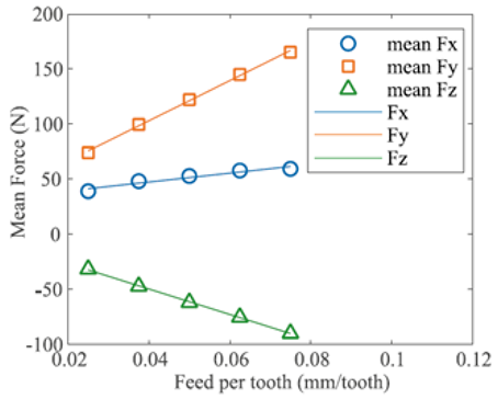 |  | 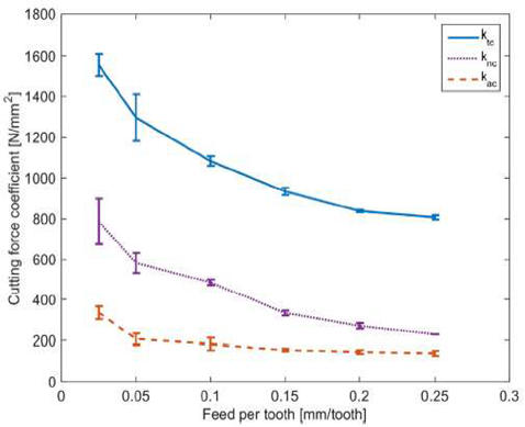 |
| Principle | linear regression | fitting | optimization |
| Formula |
3.2.2. The Extraction of Cutter–Workpiece Engagement
Cutter–workpiece engagement (CWE) refers to the contact region between the cutter and workpiece when machining at a given cutting instant, which is used to determine whether the arbitrary cutting element is in cutting or not, as shown in Figure 10. Usually, in the three−axis milling process, the workpiece shape is regular, and the tool path is simple, so the CWE can be extracted efficiently by analytical method. However, many thin−walled parts have complex geometry and generally require five−axis machining. This is often the case in milling, in which it is difficult to extract the CWE analytically because the cutter axis vector varies along the tool path, and the surfaces to be machined are mostly complex curved surfaces [133]. To address this, discrete modeling methods and solid modeling methods are two common types of methods.
Discrete modeling methods discretize the geometries of the tool and workpiece into small volume or line elements, and the contact region of the tool and workpiece is extracted by finding their contact elements (Figure 10a). The most widely used discrete modeling methods [134,136,137,138] are those based on Z−map (or Z−buffer) discrete geometric models. In the last ten years, some new methods [139,140,141] have been proposed in the class of discrete geometry methods. In general, it is necessary to strictly control the dimensions of discrete elements in order to obtain accurate tool–workpiece contact regions. Although a fine partition of discrete elements is beneficial to improve calculation accuracy, it is difficult to store data and has low computational efficiency.
In the solid modeling methods, the CWE is generally extracted by Boolean operation in the 3D CAD modeling software (Figure 10b). Larue and Altintas [142] proposed a solid modeling method in the ACIS environment to extract the contact region between the cutter and workpiece and stored the angular boundary of the portion cutting into the workpiece as a function of the coordinates of the cutter center point. Ferry et al. [143] presented a parallel slicing method to establish the CWE maps, which was used in the cutting force simulation of the five−axis milling of the engine blade. Solid modeling methods are a kind of accurate CWE extraction method with better adaptability to complex engagement conditions, but they need to perform a lot of Boolean operations, which limits their efficiency. To overcome this shortcoming, some improved methods are developed in recent studies, such as the solid trimming method [144], the arc–surface intersection method [145], etc.
The above research effort extracts the CWE purely from a geometric aspect; however, there is deformation and vibration in the machining process, especially in the thin−walled parts, which makes the actual contact area between the cutter and workpiece deviate from its nominal engagement. Sun and Jiang [135] presented an accurate model of a dynamic milling system considering the effect of force−induced deformation on CWE (Figure 10c). A similar work can be found in Ref. [146] with an improved deformation calculation model. Totis et al. [147] revealed the influence of forced vibrations on the effective cutter–workpiece contact conditions and modeled it into a milling dynamic model. Niu et al. [148] modeled the coupling relationships among CWE, time delay, and system state through analyzing teeth trajectories which consist of tool rotation, feed movement, and cutting vibrations in thin−wall milling. However, the above studies considering the physical factors only focus on a simple three−axis machining scene with respect to thin plate workpieces, and further studies are needed for the multi−axis machining process of curved thin−wall parts with more complex shapes, which undoubtedly brings challenges to the accurate extraction of CWE.
3.3. Tool Wear and Process Damping
Many key thin−walled parts in aerospace are made of difficult−to−machine materials such as titanium alloy and other superalloys. Tool wear of different forms is very common in the machining process, e.g., abrasive wear, bonding wear, diffusion wear, etc., which may produce cavities, cracks, scratch marks, grooves, tearing, surface burning, adhered materials, and other machining surface defects [149]. The tool wear will change the way of contact between the tool and the workpiece, and it will increase the resistance of the cutter. The test data [150] show that compared with the unworn tool, the peak cutting force of the nickel−based superalloy is increased by more than five times when a level−5 worn tool is used. Currently, the rapid development of advanced sensor and artificial intelligence technology has laid the foundation for identifying the tool wear status. Methods such as the optical image method [151,152] and X−ray method [153,154] can directly detect the tool wear state, but they are rarely used in the practical machining scenario due to the interference factors including strong light, oil mist, dust, and so on. Therefore, vibrations, cutting forces, acoustic emission, current, and temperature have become the most used sensor signals in online monitoring of tool wear [155,156,157].
In order to avoid faster tool wear, the spindle rotation speed is usually maintained at the level of several hundred to more than one thousand revolutions per minute. In this case, the process damping is likely to originate from the tool/workpiece interface. Different from the cutting stability in the high−speed domain which is mainly affected by the chip thickness regeneration, the cutting stability in the low−speed domain is also affected by process damping. A large quantity of research and experimental results show that process damping plays a certain role in chatter suppression when cutting many difficult−to−machine materials at low speed. Early researchers [158,159] pointed out that the dynamic plowing effect between the flank face of the tool and the machined surface of the workpiece is the main source of process damping, and the accurate identification of indentation force coefficient and the indented area is the key to characterizing the process damping. Related research works can be found in Refs. [160,161,162,163,164,165,166,167]. However, these works are based on the machining process of the rigid workpiece. It should be noted that in the machining process of thin−walled parts, the rigidity of the workpiece in the wall thickness direction is weak, and the elastic deformation of the workpiece is bound to occur under the cutting force excitation, which makes the indented area become small. Then, the contribution of the plowing effect to the process damping is weakened. At the same time, the machining process of thin−walled structure is accompanied by severe self−excited vibration, which will cause the cutting speed to deviate from its nominal direction [168]. Molnar et al. [169] studied the velocity−dependent process damping effect in the thin−wall parts milling process. This study captured the stability improvement of the milling process with large radial immersion. However, their velocity dependency model only considered the influence of the vibration in the feed direction and introduces a negative process damping for milling with low radial immersion, which resulted in a decrease in stability. This is contrary to the widely accepted experimental observations. As shown in Figure 11, Feng et al. [170] further considered the vibration of the feed direction and systematically studied the generation mechanism of the velocity−dependent process damping in thin−walled milling, improving the stability prediction accuracy under the condition of low radial immersion. In general, the research on process damping of thin−wall machining is scarce, and the formation mechanism of nonlinear process damping still needs to be further explored.
3.4. Stability Prediction Algorithm
The stability prediction of the machining process can provide theoretical guidance for optimizing the process parameters, tool geometric parameters, and so on. The DDE governing the machining dynamics with multiple DOFs and multiple modes is usually written in a matrix form. For predicting the stability of this type of DDEs, a lot of research work has been conducted in this field. The stability prediction algorithms in the literature are mainly divided into time, frequency, and discrete−time domain methods, as shown in Figure 12.
3.4.1. Frequency Domain Method
The frequency domain method consists of the zero−order approximation (ZOA) and the multi−frequency solution (MFS). Altintas and Budak [171] presented the first analytical solution, namely, the ZOA, to predict the stability lobes of milling operations in the frequency domain. This method can efficiently give the relationship between critical cutting depth and spindle speed by scanning the frequencies around the dominant structure modes, which has a clear physical meaning by directly using raw FRF measurements without identifying modal parameters [172]. In Refs. [173,174], higher−order solutions are also developed to increase the prediction accuracy of the stability in the highly intermittent machining process, e.g., the milling process of flexible workpieces at small radial immersions. Altintas et al. [175,176,177,178] extended the frequency domain method to the stability prediction of ball end milling, variable−pitch/helix milling, boring processes, etc. In recent years, the frequency domain method or its improved form [33,91,179,180] has been used in the stability analysis for the machining of thin−walled parts. For example, Yan and Zhu [179] introduced a relative transfer function to consider the dynamic characteristics of both the cutting tool and the thin−wall workpiece and employed an improved multi−frequency solution to predict the critical axial depth of cut.
3.4.2. Time Domain Method
The time domain method is the earliest method for predicting machining stability. The time−domain simulation signals, such as displacement, velocity, acceleration, or cutting forces are obtained by solving the initial value problem of DDE, and then the stability can be identified according to the convergence or divergence trend of the obtained signals over time. The time domain method can easily deal with many nonlinear effects in the milling process. Montgomery and Altintas [181] integrated process damping and stiffness into a time−domain simulation model, and they synchronously predicted the occurrence of chatter and the milling surface texture affected by chatter. Qu et al. [182] studied the machining stability in the milling of thin−walled plates and predicted a three−dimensional stability lobe diagram by time−domain simulation which employed statistical variances of the dynamic displacements as a chatter detection criterion to predict the stability lobe diagram. Rubeo and Schmitz [183] used peak−to−peak (PTP) force diagrams to predict the stability of the milling processes where the workpiece is considerably more flexible than the machine tool system. Their study showed that the PTP diagrams not only offer the global stability information as provided by the traditional SLD but also preserve the detailed local information provided by time−domain simulation. The time domain method is universal and powerful, but low computational efficiency limits its actual application. Advanced time−domain simulation techniques need to be further studied.
3.4.3. Discrete Time Domain Method
The essence of the discrete−time domain method is to use a numerical method to calculate the state transition matrix of DDE with periodic coefficients in a single period, and to construct an equivalent discrete dynamic system that approximates the original cutting dynamic system in this period. Specifically, this kind of method needs to discretize a single cutting period into a series of time intervals, convert the DDE into the state space, and semi−analytically construct the system state transition matrix on the discrete period. Then, according to Floquet theory, the relationship between the spectral radius of the state transition matrix and 1 is compared to realize the stability prediction of the machining process. Some typical discrete time domain methods include the semi−discretization method (SDM) [184,185], temporal finite element analysis (TFEA) [186], cluster treatment of characteristic roots (CTCR) method [187], Chebyshev collocation method [188], homotopy perturbation method [189], full−discretization method (FDM) [190,191], numerical integration method (NIM) [192,193], and some improved methods in accuracy or efficiency [194,195,196,197,198,199,200,201,202,203,204,205,206,207,208,209]. In Ref. [210], 3D stability prediction is achieved for the milling of thin−walled workpieces by applying the full discretization method and direct integration scheme. Recently, Zhang et al. [211] used a numerical integration method to calculate the milling SLD of the thin−walled workpiece with multiple structural modes. Niu et al. [148] proposed an efficient numerical algorithm using the discrete root finding scheme to determine the state−dependent time delay, by which the state dependency of regenerative stability and SLE are systematically investigated. Ma et al. [212] constructed a numerical algorithm with improved stability metrics to analyze the stability behaviors of trimming of thin−walled structures.
4. Chatter Avoidance/Suppression Methods and Devices
For avoiding or suppressing chatter during the machining process of thin−walled components, several classes of methods have been developed over the past few decades. It mainly includes machining parameters optimization, variable−pitch cutting tools, spindle speed variation, damping/stiffness enhancement, and active chatter control, as shown in Figure 13.
4.1. Machining Parameters Optimization
From the aspect of machining parameters optimization, constructing a stability lobe diagram (SLD) is an effective way to avoid chatter, as shown in Figure 14. Bravo et al. [13] draw three−dimensional SLDs (3D SLDs) for milling of thin−walled workpieces by simultaneously considering the flexibility of both workpiece and cutter. Jin et al. [30] utilized an extended high−order FDM to obtain the 3D SLDs (Figure 14a), which considered multiple modes of thin−walled workpieces. Niu et al. [148] developed the Runge–Kutta method [193] to analyze the stability in thin−wall milling by taking into account the feedback of vibrations. However, these studies neglected the effect of material removal on the workpiece’s dynamic characteristics. Sun et al. [135] presented a comprehensive dynamic model to plot the 3D SLDs for milling of thin−walled workpieces considering force−induced deformation, and time−varying dynamic parameters, which provides a basis for selecting more reasonable cutting depth and spindle speed. Zhang et al. [213] proposed a machining parameter optimization model for the thin−wall milling system, in which spindle speed and axial depth of cut are optimized to maximize material removal and minimize dynamic deflections under the constraint of no chatter. Germashev et al. [214] investigated the vibration response of thin−walled parts in the milling process by means of simulation and experiment. They found that the dynamic interaction between the workpiece and the cutting forces would be different under different spindle speeds, and optimal spindle speed should be selected considering the vibration amplitude of the workpiece. Sofuoglu and Orak et al. [215,216] created a hybrid decision−making algorithm to determine the optimum machining parameters. This approach may assist operators and decision makers in making correct decisions in various manufacturing environments free of chatter vibration.
In addition to optimizing the depth of cut and spindle speed, the milling chatter can also be avoided by optimizing tool orientations of regular cutting tools [217,218,219,220,221] or variable−pitch tools. Ozturk et al. [222,223] extended the frequency domain method to investigate the effect of tool orientations on the stability of five−axis ball−end milling operations, and posture SLDs are constructed. Shamoto and Akazawa [224] also presented an analytical method to predict the stability of the ball−end milling process with tool inclination, but they did not reveal the effect of lead angle on stability. Further, they presented novel strategies to optimize tool path and posture to avoid chatter [225]. Tunc et al. [226] adjusted the tool orientation from a five−axis milling path that has been pre−generated to minimize the total machine tool response time considering cutting forces, chatter stability, and machine tool motion. Sun et al. [141] also presented a method to optimize tool orientations for avoiding chatter in five−axis ball−end milling, in which the tool orientations were optimized at each tool path location by searching the feasible angular positions and checking their stability. By taking into account the process mechanics, Huang et al. [227] presented a minimax optimization approach to plan the tool orientations, by which smooth and chatter−free tool orientations can be generated. Recently, Zhao et al. [228] analyzed the effect of tool orientation on surface roughness and presented a chatter−free and interference−free tool orientations optimization algorithm. The above−mentioned work aimed at optimizing the tool orientations in milling operations with flexible cutters so as to avoid chatter, in which the flexibility of the workpiece is ignored. Huang et al. [227] presented a tool orientation optimization method to reduce the vibration and deformation in the milling process of thin−walled impeller blades. Habibi et al. [229] presented a purely geometrical approach to adjust tool orientation for reducing surface errors in the five−axis machining of thin−walled structures. They reported that the surface error was reduced by more than 90% using the presented method. However, they did not consider the effect of tool orientations on the stability of the milling process of thin−walled parts. Urbikain et al. [230] calculated the stability of barrel−shaped end milling of thin−walled parts, and comprehensively analyzed the effect of tool orientation on the dynamic force and stability. Nonetheless, it is worth noting that the machining parameters optimization strategy is inherently limited in avoiding chatter as it does not enlarge the stable machining parameter domain in the SLD.

4.2. Variable−Pitch Cutting Tools
It is well−known that regenerative chatter is closely related to the time delay of the milling system. Tuning the system time delay is an effective method to suppress regenerative chatter, which can be achieved by changing the tool geometry or adjusting the spindle speed. Next, the chatter suppression technique based on variable−pitch cutting tools is described below.
Typical variable−pitch cutting tools, which include nonuniform pitch/helix, serrated and crest−cut cutters, are shown in Figure 15. The application of variable pitch cutters for chatter suppression was first proposed by Hahn [232]. Based on a simplified milling process, Slavicek [233] analyzed the stability of variable pitch cutters. Altintas et al. [176] transformed constant regenerative time delay in uniform cutters into nonuniform multiple regenerative time delay for variable pitch cutters and designed variable pitch cutters with optimal pitch angles by an analytical stability prediction method. Based on the single frequency method [171], Budak [234,235] further proposed a simple analytical method for determining optimal pitch angles, which establishes explicit relation between the stability limit and the pitch variation. Later on, Olgac and Sipahi [236] introduced the so−called Cluster Treatment of Characteristic Roots (CTCR) approach to determine the stability limit analytically for the milling operation with a variable pitch cutter, which provides a powerful tool to determine the pitch angle formation and the optimum cutting conditions. Stepan et al. [237] proposed a brute force (BF) iterative method to optimize the face milling cutter geometry. The effectiveness of the designed variable pitch cutter was validated by laboratory and industrial experiments. Recently, Zhan et al. [231] established a five−axis variable−pitch milling model, and predicted the milling stability of ball−end cutter under different combinations of pitch angles and different tool orientations, as shown in Figure 14b. Based on the principle of maximum stable area, they also proposed an efficient optimization strategy to determine the optimal pitch angles for ball−end cutters [132].
Note that each edge of the variable pitch cutter has a fixed helix angle (Figure 15a), and therefore, the pitch angle between adjacent edges at any height on the cutting edge is the same as that at the tooltip end. However, the local pitch angles of variable helix cutters change along the tool axis (Figure 15b), and therefore, the time delay between adjacent edges changes continuously, which further disturbs the occurrence mechanism of the regenerative chatter. Turner et al. [177] modeled the milling stability model of variable helix cutters by approximating the variable helix with average pitch. They claimed that this model is only suitable for low radial immersion. Yusoff and Sims [238] used the SDM to accurately obtain the milling stability limits of variable helix cutters and then adopted the differential evolution algorithm to optimize the tool geometry. Takuya et al. [239] proposed a new method to design variable helix cutters, where the influence of the regeneration on the milling process was quantified by a “regeneration factor”. Based on the frequency domain stability model, Hayasaka et al. [240] proposed a design index () to design variable helix cutters, and the effectiveness of the proposed method was verified by milling experiments. Comak and Budak [241] presented a novel iteration method to optimize the pitch angles of variable pitch and helix cutters, which can avoid time−consuming numerical simulations. Guo et al. [242] introduced an accurate model to predict 3D surface topography in the five−axis milling of Plexiglas and metal with the variable pitch and helix cutter.
In addition to the above−mentioned variable pitch/helix cutters, serrated and crest−cut cutters are also used to suppress chatter in milling operations. Differently from variable pitch/helix cutters, they have more complex geometry, as shown in Figure 15c,d. It can be seen from Figure 15c that serrated tools have wave edges on their flank faces. Due to this special profile, the serrated tools result in non−uniform distribution of chip thickness, and the time delay may differ at any point along their flutes. Merdol and Altintas [243] and Bari et al. [244] established dynamic models and analyzed the milling stability of this type of milling cutters. Tehranizadeh et al. [245] developed a generalized mechanics and stability model of the milling process with end mills involving different serration wave shapes, including trapezoidal, sinusoidal, and circular shapes. The optimum serration profile, along with its corresponding stability, was obtained by using genetic algorithm. It is demonstrated that the stability limits are increased significantly, while the cutting forces are reduced by 30%. However, serrated tools produce periodic cutting marks on the finished surface, so the serrated tools cannot be used in finishing operations.
There is another type of milling cutter with wave edges, namely, crest−cut tools, as shown in Figure 15d. Since the wave edges are on the rake faces of the cutter, both pitch and helix angles vary continuously along the cutter axis. This type of cutter is able to provide excellent chatter suppression performance, as shown in Figure 16. In addition, it can be used for both rough machining and finishing. Dombovari and Stepan [246] and Tehranizadeh et al. [247] used the SDM to obtain the milling stability for different cases with crest−cut cutters. Tehranizadeh et al. [248] proposed a comprehensive stability model for crest−cut tools and presented a method for selecting their wave geometry to maximize stability in desired cutting conditions. In a recent study, Tehranizadeh et al. [249] investigated the chatter stability of standard cutter, variable pitch cutter, and crest−cut cutter in the milling of thin−walled parts, and they optimized the geometry of these cutting tools considering the influence of parts dynamics. They observed that crest−cut cutters have better chatter stability performance in the milling of thin−walled parts in comparison with the regular and variable pitch cutters.
From the perspective of chatter suppression, the above studies on variable−pitch cutting tools only focus on the flexibility of the cutters but ignore the weak rigidity of the workpiece when machining thin−walled parts. In addition, cutting tools may contain many other geometric parameters which also affect the machining dynamics, so there still is a lack of clear and comprehensive tool design criteria.
4.3. Spindle Speed Variation
Spindle speed variation (SSV) is another effective strategy to suppress chatter by disrupting the regenerative effect. Although the suppression principles of SSV and special tool geometries are similar, SSV has better flexibility since the variation of spindle speed can be adaptive to the variance of system process characteristics, while the special tool geometries with variable pitch/helix or special edges are not changeable once produced. The SSV strategy is generally divided into discrete spindle speed tuning (DSST) and continuous spindle speed variation (CSSV).
In DSST, the spindle speed is tuned based on measured chatter conditions, so the machining can enter the stable process. Smith et al. [250,251] presented the basic theory for chatter suppression in milling by spindle speed adaptation and investigated the possibility of monitoring the chatter vibration with sensors. Liao and Young [252] proposed a new method for online chatter suppression. In their method, the chatter frequency is identified according to the milling force signals measured in real−time, and then the chatter can be suppressed by adjusting the phase difference between the present and previous spindle speed to . Tsai et al. [253,254] used the acoustic signal to identify the milling chatter, and then they proposed an adaptive adjustment method of spindle speed. Usually, DSST is suitable for high−speed cutting conditions with few system modes.
Compared with DSST, CSSV shows strong practicability, especially in low−speed machining. There are different ways to continuously vary the spindle speed with sinusoidal [255,256,257], triangular [258], and rectangular [259] shape variations, as shown in Figure 17. Among them, the sinusoidal spindle speed variation (SSSV) is recommended as the most suitable form [257,260]. In CSSV, the variation of spindle speed needs to determine the appropriate amplitude and frequency. Many researchers applied complex and time−consuming stability simulations to determine the optimal amplitude and frequency. For example, Zatarain et al. [260] used the multi−frequency method to obtain the 3D SLD of a milling process with SSSV and triangular spindle speed variation (TSSV) and then determine the optimal design parameters in SSSV and TSSV. The results showed that SSSV is more effective than TSSV in suppressing chatter in low−speed machining. Niu et al. [261] proposed a variable−step numerical integration method to analyze the stability and optimize the design parameters for the milling processes with CSSV, which can reduce the computation time and improve the efficiency in calculating the 3D SLD. However, the dynamic characteristics of the milling process especially the thin−wall milling process generally vary and ultimately lead to the change in the 3D SLD. Therefore, the effects of the above−mentioned design methods [258,260,261] cannot be guaranteed in actual machining. Al−Regib et al. [256] proposed simple criteria to select the optimal design parameters in SSSV depending on the measured chatter frequency. Recently, Yamato et al. [262] presented a practical design method for optimal SSSV based on the minimization of kinematic internal process energy balance, which was verified by a series of time−domain simulations and boring experiments.
4.4. Damping/Stiffness Enhancement
During the machining of thin−walled components, two main reasons for the chatter are the weak rigidity and the low damping of the machining system. Thus, to suppress or avoid the machining chatter, these two aspects should be considered as shown in Figure 18.
From the aspect of stiffness enhancement, supporting fixtures and double−sided machining can be used, as shown in Figure 19. For using supporting fixtures, Aoyama et al. [263] proposed a new fixture device with multi−pin supports to increase the stiffness of a thin plate. The results showed that the vibration amplitude of the thin plate at the resonance frequency decreased by about 66%. Kolluru et al. [264] presented a novel torsion spring ancillary device to improve the stiffness of a thin−walled casing for minimizing the chatter vibrations during its milling process (Figure 19a). Similarly, Wang et al. [265] designed a new flexible fixture to hold a thin−walled casing, which reduced the vibration amplitude of the workpiece by about 20 times. Zeng et al. [266] introduced a fixture design approach for suppressing the machining vibration of a flexible workpiece, by which the element location, the element number, and the applied force can be simultaneously optimized (Figure 19b). It is worth noting that the above fixtures are fixed.
In recent years, moving support technology has been receiving more and more attention. Matsubara et al. [271] developed a simple pivot support to suppress the vibrations in milling thin−walled parts. The experimental results showed that pivot support could provide a better vibration suppression performance compared to the fixed pivot. Fei et al. [268,272] presented a moving damper to support the back surface of a thin−wall part to suppress chatter and workpiece deformation. The moving damper was realized by connecting an auxiliary device to the spindle of the machine tool (Figure 19c). Wan et al. [267] also designed a moving device to suppress the chatter vibrations, by which the surface quality of the workpiece is obviously improved (Figure 19d).
Double−sided machining is also an efficient way to increase workpiece stiffness. Shamoto et al. [270] used two cutters simultaneously to roughly mill both sides of the thin plate (Figure 19e). Their study showed that both the machining efficiency and the machined flatness are improved about three times that of the conventional one-sided face milling, but it will cause light forced vibrations. To address this problem, Mori et al. [273] attempted to use synchronized single−tooth cutters for machining to effectively suppress the forced vibrations. Recently, Fu et al. [269] used dual collaborative parallel kinematic machines to machine the thin-walled parts with double−sided features (Figure 19f), which obtained good chatter suppression results and further improved productivity.
In addition to the above method, adding sacrificial structure and optimizing the material removal process are also effective chatter suppression methods from the perspective of stiffness enhancement. The sacrificial structure is not part of the finished component, but it can support the thin-walled part during machining. Smith et al. [274] used sacrificial structures to increase the stiffness of the walls during roughing and semi−finishing (Figure 20a). Alan et al. [275] compared different cutting strategies for increasing the chatter−free material removal rate considering workpiece dynamics. Luo et al. [276] further presented a method for optimizing the material removal sequence. They experimentally proved that such optimization can improve the stability in milling thin−walled parts. Lutfi et al. [277] proposed a method to select the stock thickness, stock shape, and tool axis to improve the stability of thin−wall parts during five−axis ball−end milling (Figure 20b). Recently, Wu et al. [278] proposed a method to optimize the machining allowance distribution of integral impellers in milling. Their simulation results showed that the machining system stiffness with non−uniform allowance is two times that of uniform allowance, and the limit of chatter stability is increased by three times.
Increasing the damping of the machining system can also suppress the chatter vibration during the machining of thin−walled parts. Passive damping can dissipate the vibration energy without any external power supply, and it has been widely used in machining processes for chatter suppression. There are different types of passive damping devices, such as the impact damper, friction damper, and tuned mass damper (TMD), as shown in Figure 21. Among them, the TMD is the most commonly used one due to its easy implementation and low cost. The TMD consists of a mass, a spring, and a damping. The parameters of the whole damper can be tuned to suppress the specific modes of the workpiece or machine tool. Bolsunovsky et al. [279] applied a damper in the machining of thin−wall workpiece, which reduces the workpiece vibrations by 20 times (Figure 21a). Hamed et al. [280] used a TMD to suppress the chatter in the milling of cantilever plates with nonlinear milling force and optimized the absorber position and its spring stiffness. Yuan et al. [281] implemented a TMD to suppress the chatter in the milling of cylindrical parts. The results showed that using TMD during machining can reduce vibrations and improve stability limits. Taking the material removal process into consideration, Yang et al. [282] and Yuan et al. [283] proposed passive dampers with tunable stiffness to suppress the chatter in thin−walled part milling. It is worth noting that a single−degree−of−freedom TMD can only suppress a single mode of vibrations, and sometimes, the chatter may be affected by multiple modes of the machining system. To suppress the milling vibration of the workpiece with two main modes, Yang et al. [284,285] proposed a two−degrees−of−freedom TMD. Wan et al. [286] attached multiple masses to the thin−wall workpiece for suppressing multi−modal vibration in the milling process and optimized the number and position of the masses (Figure 21b). Recently, Nakano et al. [287] attached multiple TMDs to the thin−walled cylinder for chatter suppression and investigated the effect of the mounting arrangement of the TMDs (Figure 21c).
Many researchers have proposed to add the damping material/structure to the un−machining surface of the workpiece to improve the structural damping of thin−walled workpieces, as shown in Figure 22. For instance, Kolluru et al. [88] proposed a surface damping solution to minimize the vibrations of the thin−walled workpiece during milling, and the solution was composed of viscoelastic damping layer and distributed masses (Figure 22a). The results show the vibration amplitude can be reduced by 4.2 times using the proposed damping solution. Shi et al. [288] designed a constrained layer damper for vibration suppression in thin−walled component milling. With the local surface damper, the vibration amplitude is reduced by 80%. Scalzo et al. [289] integrated the high−damping lattice structures on the workpiece surface, and the machining stability is obviously improved. In addition, viscous fluid can be also used to increase the structural damping. Zhang et al. [290,291] presented a new approach by submerging the workpiece into the viscous fluid to improve the machining stability. Dang et al. [292] added the viscous fluid into the pocket of the workpiece to mitigate chatter during the milling process of the thin−walled workpiece (Figure 22b). Results demonstrated that the chatter vibration can be well suppressed, and the MRR can be increased by more than 140% after using the viscous fluid.
4.5. Active Chatter Control
Differently from passive chatter suppression methods, the active chatter control methods adopt appropriate sensors to monitor the current state of machining processes and then apply active forces with actuators to suppress the chatter vibration as shown in Figure 23. According to the position of the actuators, the active control systems can be classified into three main categories: active spindle system, active tool holder, and active workpiece holder.
The active spindle system can produce forces to the rotating shaft for chatter suppression [293] (Figure 23a). Denkena et al. [294] placed three piezo actuators around the spindle to generate superposed vibrations in the feed direction, which can disturb the regenerative effect and suppress the chatter. Monnin et al. [96,97] integrated piezoelectric actuators into the spindle system and proposed two different control strategies to control the front bearing position of the spindle, which can enlarge the stability limits at certain desired spindle speed range. By integrating an active magnetic bearing into the spindle, Dijk et al. [295,296] presented a robust chatter control strategy to suppress the chatter during high−speed milling and verified the effectiveness of the presented strategy. Similarly, Wan et al. [297,298] integrated an electromagnetic actuator into the spindle and presented a sliding mode control method and a discrete output feedback robust controller for suppressing the chatter. The experimental results showed that the stability was improved significantly over a wide spindle speed. Aiming at suppressing the chatter in the machining of thin−walled workpieces, Li et al. [299] designed an active chatter control structure by integrating piezoelectric actuators and displacement sensors into the spindle–tool–workpiece system. The maximum material removal rate was significantly improved by using the proposed control structure.
In terms of the active tool holder, Wang et al. [300] proposed a stiffness variation method to suppress milling chatter, in which piezoelectric stack actuators acted on a special tool holder. Vashisht et al. [301] applied an electromagnetic actuator near the boring bar’s end and proposed an optimal fractional order PD lambda controller to mitigate the chatter. They reported that the critical depth of cut was increased by two times with a limited actuator size. Basovich et al. [302] designed an active slender bar structure that integrated electromagnetic actuators and eddy current sensors, and developed a robust stabilizing controller. The experimental results showed that the stability was improved by about 100%. Saleh et al. [303,304] integrated magnetorheological fluid into the boring bar to actively increase the damping of the machining system (Figure 23b, and significantly increased stability limits are obtained. Bahador et al. [305] designed a novel tool fixture to suppress the chatter in hard turning processes. The designed tool fixture is mainly composed of a piezoelectric actuator and stiffeners (Figure 23c), by which the chatter was effectively suppressed, and the surface roughness was improved.
The active workpiece holder can compensate for the relative vibrations between a cutter and a workpiece to suppress the machining chatter. With the purpose of alleviating the chatter in machining the thin−walled workpiece, many researchers proposed a variety of active workpiece holders. For example, Zhang et al. [306] reduced the vibrations of the thin−walled workpiece by mounting piezoelectric actuators and sensors to the workpiece surface. The experimental results showed that the critical cutting depth can be increased by seven times using the proposed control method. Parus et al. [307] used a piezoelectric actuator and a Linear Quadratic Gaussian algorithm to form an active fixture system that alleviated the machining vibration of the flexible workpiece. Jia et al. [308] proposed a force−tunable pneumatic fixture to provide support on the workpiece to mitigate vibrations and improve stability limits. They systematically investigated the influence of fixture support force on the milling dynamics of the thin−walled workpiece (Figure 23d). Ozturk et al. [106,309] employed a robot to provide mobile support to actively increase the stiffness of the thin−wall parts, and consequently, the stability of the milling process was improved. Guo et al. [310] conducted a systematic review of robotic milling of complex parts. Beudaert et al. [311] designed a portable and tunable electromagnetic actuator to suppress the chatter by changing the damping of the thin−walled part (Figure 23e). Jiang et al. [312] designed a magnetorheological fluid flexible fixture to fix the thin−walled part, which improved the surface finish quality.
Figure 23.
Chatter suppression using active control methods [293,303,304,305,308,309]. (a) Active spindle. (b) Active slender bar. (c) Active boring bar with MR damper. (d) Force-tunable pneumatic fixture. (e) Mobile support by a robot.

In recent years, many researchers have attempted to design better controllers or control algorithms to improve the response speed of the designed devices/systems, so as to more accurately control the machining processes. For example, Paul et al. [313] applied an intelligent PD/PID controller combined with fuzzy logic to reduce chatter in the milling processes. The results showed that the proposed controller performed better than the classical PD/PID controllers. Wang et al. [314] adopted the adaptive vibration reshaping algorithm to precisely modify and control the milling vibration frequencies, which can suppress chatter frequencies effectively. Based on the delay−dependent output feedback controller synthesis, Mizrachi et al. [315] presented a control method for chatter suppression in the internal turning of the flexible bar with consideration of the hardware limitations, the uncertainties of the bar model, and the delayed dynamics of the regenerative chatter. The above active devices/systems change the dynamic characteristics of the machining system and thereby enlarge the stability domains in the SLD. However, the implementations of these active control methods require many auxiliary devices. This not only requires sensors, actuators, and controllers but also needs complex control algorithms and consumes a lot of energy. Meanwhile, these auxiliaries are easily damaged due to the harsh machining environment, such as coolants, chips, and so on. These factors limit the application of the active control method in actual thin−wall machining.
5. Discussion and Future Prospects
5.1. Identification of System Dynamic Characteristics
With the improvement of the performance requirements, the shapes of the thin−walled parts are increasingly complex. At this time, the methods based on FEMA are the most suitable methods to identify the in−process dynamic parameters for the thin−walled parts. However, existing methods sometimes oversimplify the FE models, which could hardly apply to the time−varying cutting conditions under complex clamping conditions. In addition, in the practical use of the FEMA−based methods, the calculation efficiency issue is also a major limitation. Although the methods combined with the structural dynamics modification scheme can improve the calculation efficiency to some extent, it is still necessary to develop more efficient and applicable methods for more complex thin−walled structures, especially when involving damping, support, and lubrication boundary conditions.
As for slender cutting tools, EMA−based methods are preferred in theoretical research and practical application. To minimize the number of standard impact test, the RCSA theory was developed to predict the tool tip acceptance for tool–holder–spindle−machine assemblies. It is noted that in some processing machines, such as birotary milling machines and industrial robots, the cutting tool presents the dynamic characteristics of pose dependence. Data−driven and statistical methods can be employed to obtain the pose−dependent structural dynamic parameters. However, they are unable to mechanistically investigate the laws governing the changes in the dynamics. In addition, in the case of high−speed machining, the dynamics of the rotating cutting tool exhibit in−process variations due to the effect of the gyroscopic moments and centrifugal forces.
5.2. Modeling and Prediction of Chatter Stability
Obviously, differently from the machining of simple rigid parts, during the thin−walled machining process, the interaction between the thin−walled part and cutting tool is more complex, especially with the application of difficult−to−machine materials. Its accurate dynamics modeling is very challenging because the machining system exhibits complex nonlinear behavior. The nonlinear dynamic cutting force model should be accurately calibrated, and the real contact region between the cutting tool and thin−walled parts should be accurately extracted. Future research should further study the nonlinear tool/workpiece interaction mechanism, clarify the influence mechanism of tool wear and process damping on thin−wall machining dynamics, and establish a reliable and accurate cutting dynamic model with real tool–part engagement conditions.
Note that when considering the influence of more physical factors, e.g., deformation, vibration, and cutter runout, although the CWE extraction becomes more accurate, in the meantime, it is also difficult to operate in complex working conditions, and the consumed computation time will increase significantly. Therefore, advanced methods with better practicability and higher computational efficiency need to be explored further. In addition, the multiple process damping effects may coexist in the machining process of thin−walled structural parts, and the contribution ratio is closely related to the time−varying stiffness of the workpiece [316]. In particular, in the five−axis machining of the complex curved surface workpiece, the change in tool axis vector leads to the imbalance of cutting load and the changeable cutting tool–workpiece engagement relationship, so its influence on tool wear and process damping needs to be further studied.
The dynamic equation of the thin−wall machining system is nonlinear with a complex delay, especially when the wall thickness of the workpiece reaches a very thin semi−finishing or finishing stage. Complex nonlinear problems may lead to the difficulty of applying frequency−domain methods and discrete−time domain methods to the prediction of machining stability. The stability−solving research may depend on the time−domain methods in the future. However, because of the low computational efficiency, multiple modes of thin−wall machining system, and large matrix dimension of the dynamic equation, it is necessary to combine time−domain methods with advanced numerical computing techniques, and to develop more efficient time−domain stability criteria.
5.3. Chatter Avoidance/Suppression Methods and Devices
Tool geometry optimization at the design stage can effectively increase cutting stability, and therefore, more and more attention has been paid to the optimization design of tool edge profile and internal structure with innovative features. However, the existing tool design criteria are relatively simple, such as minimizing cutting force, maximizing machining stability, or smoothing the finishing surface. Moreover, from the perspective of dynamics, most studies only focus on the optimization of helix angles and pitch angles. In fact, tool geometry includes many angles and other geometric parameters, i.e., pitch angles, helix angles, rake angles, clearance angles, honed radius, etc. Future research should establish a more comprehensive optimization objective, and simultaneously optimize multiple geometric parameters. At the same time, as constraint conditions, the tool strength and manufacturing difficulty should be fully considered.
The improvement of stiffness and damping for thin−wall machining systems can directly suppress machining chatter. Many novel fixtures and damping devices have been proposed, which effectively take advantage of the stiffness increase obtained by the clamping and support units and the damping increase obtained by the active and passive damping devices. However, it should be noted that some fixed devices cannot match the time−varying dynamic characteristics of thin−wall parts due to a lot of material removal. Therefore, mobile fixture devices and double−sided machining have currently gained more and more scholars’ research interests. Considering the limited operational space of some thin−walled parts with complex structural features, it is also a good research idea to adopt a sacrificed structure or optimize the material removal sequence to make the remaining unremoved materials play a supporting role, which should also be paid more attention in future research.
The active devices/systems can significantly improve the dynamic characteristics of the machining system and enlarge the stability domains of machining parameters, but they need to configure many auxiliary devices, e.g., actuators, controllers, etc., and also require complex control algorithms. These devices are easily damaged due to harsh conditions in the machining environment, e.g., humidity, impact, etc. This limits their application. Future research can make full use of built−in sensors and/or external sensors to establish reliable communication with the CNC control system. Based on collected signals by the sensors, intelligent monitoring models with rapid recognition of chatter should be established. The speed and feed parameters are adjusted in real−time through the CNC control system to achieve the purpose of eliminating chatter.
6. Conclusions
In the machining of weak−rigidity thin−walled parts, chatter instability is the main factor that reduces surface machining quality and restricts production efficiency. Therefore, it is very important to develop an accurate stability analysis method and effective chatter suppression technology for the high−performance machining of thin−walled parts. This paper comprehensively reviews the research on dynamic characteristic identification, chatter stability modeling, and chatter suppression of thin−walled machining systems, and the research status of regenerative chatter in thin−walled machining is systematically described. As can be seen, significant progress has been made in the past decade, during which time many efficient identification methods for time−varying dynamic characteristics, chatter stability models considering the system stiffness at different machining stages, and various effective chatter avoidance/suppression strategies are proposed. This paper conducted a critical review of the relevant literature. The existing problems in the study of thin−wall machining dynamics are discussed in the meantime with concluding future research work.
Author Contributions
Conceptualization, Y.S.; data curation, M.Z. and S.J.; writing-original draft preparation, S.J., Y.S., D.Z., R.W. and M.Z.; writing-review and editing, Y.S. and S.J.; supervision, Y.S. and S.J. All authors have read and agreed to the published version of the manuscript.
Funding
This research was funded by the National Natural Science Foundation of China (Grant Nos. U22A20202 and 5220053301).
Institutional Review Board Statement
Not applicable.
Informed Consent Statement
Not applicable.
Data Availability Statement
Not applicable.
Acknowledgments
Special thanks go to the Key Laboratory of Vehicle Advanced Manufacturing, Measuring and Control Technology for supporting this work.
Conflicts of Interest
The authors declare that they have no known competing financial interest or personal relationship that could have appeared to influence the work reported in this paper.
References
- Herranz, S.; Campa, F.J.; De Lacalle, L.N.L.; Rivero, A.; Lamikiz, A.; Ukar, E.; Sánchez, J.A.; Bravo, U. The Milling of Airframe Components with Low Rigidity: A General Approach to Avoid Static and Dynamic Problems. Proc. Inst. Mech. Eng. Part B J. Eng. Manuf. 2005, 219, 789–801. [Google Scholar] [CrossRef]
- Izamshah, R.A.R.; Mo, J.P.T.; Ding, S. Finite Element Analysis of Machining Thin-Wall Parts. Key Eng. Mater. 2011, 458, 283–288. [Google Scholar] [CrossRef]
- Taylor, F.W. On the Art of Cutting Metals; American Society of Mechanical Engineers: New York, NY, USA, 1906; Volume 23. [Google Scholar]
- Quintana, G.; Ciurana, J. Chatter in Machining Processes: A Review. Int. J. Mach. Tools Manuf. 2011, 51, 363–376. [Google Scholar] [CrossRef]
- Altintas, Y. Manufacturing Automation: Metal Cutting Mechanics, Machine Tool Vibrations, and CNC Design, 2nd ed.; Cambridge University Press: New York, NY, USA, 2012. [Google Scholar]
- Munoa, J.; Beudaert, X.; Dombovari, Z.; Altintas, Y.; Budak, E.; Brecher, C.; Stepan, G. Chatter Suppression Techniques in Metal Cutting. CIRP Ann. Manuf. Technol. 2016, 65, 785–808. [Google Scholar] [CrossRef]
- Li, Z.; Sun, Y.; Guo, D. Chatter Prediction Utilizing Stability Lobes with Process Damping in Finish Milling of Titanium Alloy Thin-Walled Workpiece. Int. J. Adv. Manuf. Technol. 2017, 89, 2663–2674. [Google Scholar] [CrossRef]
- Altintas, Y.; Weck, M. Chatter Stability of Metal Cutting and Grinding. CIRP Ann. 2004, 53, 619–642. [Google Scholar] [CrossRef]
- Altintas, Y.; Stépán, G.; Budak, E.; Schmitz, T.; Kilic, Z.M. Chatter Stability of Machining Operations. ASME J. Manuf. Sci. Eng. 2020, 142, 110801. [Google Scholar] [CrossRef]
- Siddhpura, M.; Paurobally, R. A Review of Chatter Vibration Research in Turning. Int. J. Mach. Tools Manuf. 2012, 61, 27–47. [Google Scholar] [CrossRef]
- Zhu, L.; Liu, C. Recent Progress of Chatter Prediction, Detection and Suppression in Milling. Mech. Syst. Signal Process. 2020, 143, 106840. [Google Scholar] [CrossRef]
- Ismail, F.; Ziaei, R. Chatter Suppression in Five-Axis Machining of Flexible Parts. Int. J. Mach. Tools Manuf. 2002, 42, 115–122. [Google Scholar] [CrossRef]
- Bravo, U.; Altuzarra, O.; López De Lacalle, L.N.; Sánchez, J.A.; Campa, F.J. Stability Limits of Milling Considering the Flexibility of the Workpiece and the Machine. Int. J. Mach. Tools Manuf. 2005, 45, 1669–1680. [Google Scholar] [CrossRef]
- Nikolaev, S.; Kiselev, I.; Kuts, V.; Voronov, S. Optimal Milling Modes Identification of a Jet-Engine Blade Using Time-Domain Technique. Int. J. Adv. Manuf. Technol. 2020, 107, 1983–1992. [Google Scholar] [CrossRef]
- Meshreki, M.; Kövecses, J.; Attia, H.; Tounsi, N. Dynamics Modeling and Analysis of Thin-Walled Aerospace Structures for Fixture Design in Multiaxis Milling. J. Manuf. Sci. Eng. 2008, 130, 310111–3101112. [Google Scholar] [CrossRef]
- Schmitz, T.L.; Honeycutt, A. Analytical Solutions for Fixed-Free Beam Dynamics in Thin Rib Machining. J. Manuf. Process. 2017, 30, 41–50. [Google Scholar] [CrossRef]
- Song, Q.; Shi, J.; Liu, Z.; Wan, Y. A Time-Space Discretization Method in Milling Stability Prediction of Thin-Walled Component. Int. J. Adv. Manuf. Technol. 2017, 89, 2675–2689. [Google Scholar] [CrossRef]
- Fei, J.; Lin, B.; Yan, S.; Ding, M.; Zhang, X.; Zhang, J.; Lan, J. Theoretical Prediction and Experimental Validation of Dynamic Deformation during Machining of Thin-Walled Structure. ASME Int. Mech. Eng. Congr. Expo. Proc. 2017, 2, V002T02A004. [Google Scholar] [CrossRef]
- Shi, J.; Song, Q.; Liu, Z.; Wan, Y. Formulating a Numerically Low-Cost Method of a Constrained Layer Damper for Vibration Suppression in Thin-Walled Component Milling and Experimental Validation. Int. J. Mech. Sci. 2017, 128–129, 294–311. [Google Scholar] [CrossRef]
- Shi, J.; Song, Q.; Liu, Z.; Ai, X. A Novel Stability Prediction Approach for Thin-Walled Component Milling Considering Material Removing Process. Chin. J. Aeronaut. 2017, 30, 1789–1798. [Google Scholar] [CrossRef]
- Liu, Y.; Wu, B.; Luo, M.; Zhang, D. Modeling and Cutting Path Optimization of Shallow Shell Considering Its Varying Dynamics During Machining. Procedia CIRP 2015, 31, 521–526. [Google Scholar] [CrossRef] [Green Version]
- Ahmadi, K. Finite Strip Modeling of the Varying Dynamics of Thin-Walled Pocket Structures during Machining. Int. J. Adv. Manuf. Technol. 2017, 89, 2691–2699. [Google Scholar] [CrossRef]
- Baker, J.R.; Rouch, K.E. Use of Finite Element Structural Models in Analyzing Machine Tool Chatter. Finite Elem. Anal. Des. 2002, 38, 1029–1046. [Google Scholar] [CrossRef]
- Elbestawi, M.A.; Sagherian, R. Dynamic modeling for the prediction of surface errors in the milling of thin-walled sections. J. Mater. Process. Technol. 1991, 25, 215–228. [Google Scholar] [CrossRef]
- Altintas, Y.; Montgomery, D.; Budak, E. Dynamic Peripheral Milling of Flexible Structures. J. Eng. Ind. 1992, 114, 137–145. [Google Scholar] [CrossRef]
- Seguy, S.; Dessein, G.; Arnaud, L. Surface Roughness Variation of Thin Wall Milling, Related to Modal Interactions. Int. J. Mach. Tools Manuf. 2008, 48, 261–274. [Google Scholar] [CrossRef] [Green Version]
- Mañé, I.; Gagnol, V.; Bouzgarrou, B.C.; Ray, P. Stability-Based Spindle Speed Control during Flexible Workpiece High-Speed Milling. Int. J. Mach. Tools Manuf. 2008, 48, 184–194. [Google Scholar] [CrossRef]
- Thevenot, V.; Arnaud, L.; Dessein, G.; Cazenave-Larroche, G. Integration of Dynamic Behaviour Variations in the Stability Lobes Method: 3D Lobes Construction and Application to Thin-Walled Structure Milling. Int. J. Adv. Manuf. Technol. 2006, 27, 638–644. [Google Scholar] [CrossRef] [Green Version]
- Zhang, X.J.; Xiong, C.H.; Ding, Y.; Zhang, X.M. Stability Analysis in Milling of Thin-Walled Workpieces with Emphasis on the Structural Effect. Proc. Inst. Mech. Eng. Part B J. Eng. Manuf. 2010, 224, 589–608. [Google Scholar] [CrossRef]
- Jin, X.; Sun, Y.; Guo, Q.; Guo, D. 3D Stability Lobe Considering the Helix Angle Effect in Thin-Wall Milling. Int. J. Adv. Manuf. Technol. 2016, 82, 2123–2136. [Google Scholar] [CrossRef]
- Campa, F.J.; Lopez de Lacalle, L.N.; Celaya, A. Chatter Avoidance in the Milling of Thin Floors with Bull-Nose End Mills: Model and Stability Diagrams. Int. J. Mach. Tools Manuf. 2011, 51, 43–53. [Google Scholar] [CrossRef] [Green Version]
- Thevenot, V.; Arnaud, L.; Dessein, G.; Cazenave-Larroche, G. Influence of Material Removal on the Dynamic Behavior of Thin-Walled Structures in Peripheral Milling. Mach. Sci. Technol. 2006, 10, 275–287. [Google Scholar] [CrossRef]
- Ding, Y.; Zhu, L. Investigation on Chatter Stability of Thin-Walled Parts Considering Its Flexibility Based on Finite Element Analysis. Int. J. Adv. Manuf. Technol. 2018, 94, 3173–3187. [Google Scholar] [CrossRef]
- Budak, E.; Tunç, L.T.; Alan, S.; Özgüven, H.N. Prediction of Workpiece Dynamics and Its Effects on Chatter Stability in Milling. CIRP Ann. Manuf. Technol. 2012, 61, 339–342. [Google Scholar] [CrossRef]
- Yue, C.; Gao, H.; Liu, X.; Wang, L.; Liang, S.Y. Analytical Prediction of Part Dynamics and Process Damping for Machining Stability Analysis. In 51st Cirp Conference on Manufacturing Systems; Wang, L., Ed.; Procedia CIRP: Stockholm, Sweden, 16–18 May 2018; Volume 72, pp. 1463–1468.
- Song, Q.; Liu, Z.; Wan, Y.; Ju, G.; Shi, J. Application of Sherman-Morrison-Woodbury Formulas in Instantaneous Dynamic of Peripheral Milling for Thin-Walled Component. Int. J. Mech. Sci. 2015, 96–97, 79–90. [Google Scholar] [CrossRef]
- Wang, X.; Song, Q.; Liu, Z. Position-Dependent Stability Prediction for Multi-Axis Milling of the Thin-Walled Component with a Curved Surface. Appl. Sci. 2020, 10, 8779. [Google Scholar] [CrossRef]
- Yang, Y.; Zhang, W.H.; Ma, Y.C.; Wan, M. Chatter Prediction for the Peripheral Milling of Thin-Walled Workpieces with Curved Surfaces. Int. J. Mach. Tools Manuf. 2016, 109, 36–48. [Google Scholar] [CrossRef]
- Tuysuz, O.; Altintas, Y. Frequency Domain Updating of Thin-Walled Workpiece Dynamics Using Reduced Order Substructuring Method in Machining. J. Manuf. Sci. Eng. 2017, 139, 071013. [Google Scholar] [CrossRef]
- Tuysuz, O.; Altintas, Y. Time-Domain Modeling of Varying Dynamic Characteristics in Thin-Wall Machining Using Perturbation and Reduced-Order Substructuring Methods. J. Manuf. Sci. Eng. Trans. ASME 2018, 140, 011015. [Google Scholar] [CrossRef]
- Yang, Y.; Zhang, W.H.; Ma, Y.C.; Wan, M.; Dang, X. Bin. An Efficient Decomposition-Condensation Method for Chatter Prediction in Milling Large-Scale Thin-Walled Structures. Mech. Syst. Signal Process. 2019, 121, 58–76. [Google Scholar] [CrossRef]
- Tian, W.; Ren, J.; Zhou, J.; Wang, D. Dynamic Modal Prediction and Experimental Study of Thin-Walled Workpiece Removal Based on Perturbation Method. Int. J. Adv. Manuf. Technol. 2018, 94, 2099–2113. [Google Scholar] [CrossRef]
- Zhao, L.; Jin, D.; Wang, H.; Liu, C. Modal Parameter Identification of Time-Varying Systems via Wavelet-Based Frequency Response Function. Arch. Appl. Mech. 2020, 90, 2529–2542. [Google Scholar] [CrossRef]
- Li, W.; Wang, L.; Yu, G.; Wang, D. Time-Varying Dynamics Updating Method for Chatter Prediction in Thin-Walled Part Milling Process. Mech. Syst. Signal Process. 2021, 159, 107840. [Google Scholar] [CrossRef]
- Tang, Y.; Zhang, J.; Zhang, H.; Zhao, W.; Liu, H. Generalized Equivalent Method for Dynamics of Multipocket Thin-Walled Parts. Int. J. Adv. Manuf. Technol. 2022, 120, 2731–2745. [Google Scholar] [CrossRef]
- Dang, X.B.; Wan, M.; Yang, Y.; Zhang, W.H. Efficient Prediction of Varying Dynamic Characteristics in Thin-Wall Milling Using Freedom and Mode Reduction Methods. Int. J. Mech. Sci. 2019, 150, 202–216. [Google Scholar] [CrossRef]
- Wang, C.; Zhang, X.; Chen, X.; Cao, H. Time-Varying Chatter Frequency Characteristics in Thin-Walled Workpiece Milling with B-Spline Wavelet on Interval Finite Element Method. J. Manuf. Sci. Eng. 2019, 141, 51008. [Google Scholar] [CrossRef]
- Wang, D.; Ren, J.; Tian, W.; Shi, K.; Zhang, B. Predicting the Dynamics of Thin-Walled Parts with Curved Surfaces in Milling Based on FEM and Taylor Series. Int. J. Adv. Manuf. Technol. 2019, 103, 927–942. [Google Scholar] [CrossRef]
- Kiss, A.K.; Hajdu, D.; Bachrathy, D.; Stepan, G. Operational Stability Prediction in Milling Based on Impact Tests. Mech. Syst. Signal Process. 2018, 103, 327–339. [Google Scholar] [CrossRef] [Green Version]
- Gradišek, J.; Kalveram, M.; Insperger, T.; Weinert, K.; Stépán, G.; Govekar, E.; Grabec, I. On Stability Prediction for Milling. Int. J. Mach. Tools Manuf. 2005, 45, 769–781. [Google Scholar] [CrossRef]
- Zhang, X.J.; Xiong, C.H.; Ding, Y.; Feng, M.J.; Xiong, Y.L. Milling Stability Analysis with Simultaneously Considering the Structural Mode Coupling Effect and Regenerative Effect. Int. J. Mach. Tools Manuf. 2012, 53, 127–140. [Google Scholar] [CrossRef]
- Li, H.; Shin, Y.C. A Comprehensive Dynamic End Milling Simulation Model. J. Manuf. Sci. Eng. 2006, 128, 86–95. [Google Scholar] [CrossRef]
- Eksioglu, C.; Kilic, Z.M.; Altintas, Y. Discrete-Time Prediction of Chatter Stability, Cutting Forces, and Surface Location Errors in Flexible Milling Systems. J. Manuf. Sci. Eng. ASME 2012, 134, 061006. [Google Scholar] [CrossRef]
- Jiang, S.; Sun, Y. Stability Analysis for a Milling System Considering Multi-Point-Contact Cross-Axis Mode Coupling and Cutter Run-out Effects. Mech. Syst. Signal Process. 2020, 141, 106452. [Google Scholar] [CrossRef]
- Faassen, R.P.H.; Van de Wouw, N.; Oosterling, J.A.J.; Nijmeijer, H. Prediction of Regenerative Chatter by Modelling and Analysis of High-Speed Milling. Int. J. Mach. Tools Manuf. 2003, 43, 1437–1446. [Google Scholar] [CrossRef]
- Rantatalo, M.; Aidanpää, J.O.; Göransson, B.; Norman, P. Milling Machine Spindle Analysis Using FEM and Non-Contact Spindle Excitation and Response Measurement. Int. J. Mach. Tools Manuf. 2007, 47, 1034–1045. [Google Scholar] [CrossRef]
- Tatar, K.; Gren, P. Measurement of Milling Tool Vibrations during Cutting Using Laser Vibrometry. Int. J. Mach. Tools Manuf. 2008, 48, 380–387. [Google Scholar] [CrossRef]
- Tatar, K.; Rantatalo, M.; Gren, P. Laser Vibrometry Measurements of an Optically Smooth Rotating Spindle. Mech. Syst. Signal Process. 2007, 21, 1739–1745. [Google Scholar] [CrossRef]
- Zaghbani, I.; Songmene, V. Estimation of Machine-Tool Dynamic Parameters during Machining Operation through Operational Modal Analysis. Int. J. Mach. Tools Manuf. 2009, 49, 947–957. [Google Scholar] [CrossRef]
- Gagnol, V.; Le, T.P.; Ray, P. Modal Identification of Spindle-Tool Unit in High-Speed Machining. Mech. Syst. Signal Process. 2011, 25, 2388–2398. [Google Scholar] [CrossRef]
- Li, B.; Cai, H.; Mao, X.; Huang, J.; Luo, B. Estimation of CNC Machine-Tool Dynamic Parameters Based on Random Cutting Excitation through Operational Modal Analysis. Int. J. Mach. Tools Manuf. 2013, 71, 26–40. [Google Scholar] [CrossRef]
- Schmitz, T.L.; Davies, M.A.; Kennedy, M.D. Tool Point Frequency Response Prediction for High-Speed Machining by Rcsa. J. Manuf. Sci. Eng. Trans. ASME 2001, 123, 700–707. [Google Scholar] [CrossRef]
- Schmitz, T.; Betters, E.; Budak, E.; Yüksel, E.; Park, S.; Altintas, Y. Review and Status of Tool Tip Frequency Response Function Prediction Using Receptance Coupling. Precis. Eng. 2022, 79, 60–77. [Google Scholar] [CrossRef]
- Schmitz, T.L.; Powell, K.; Won, D.; Scott Duncan, G.; Gregory Sawyer, W.; Ziegert, J.C. Shrink Fit Tool Holder Connection Stiffness/damping Modeling for Frequency Response Prediction in Milling. Int. J. Mach. Tools Manuf. 2007, 47, 1368–1380. [Google Scholar] [CrossRef]
- Ealo, J.A.; Garitaonandia, I.; Fernandes, M.H.; Hernandez-Vazquez, J.M.; Muñoa, J. A Practical Study of Joints in Three-Dimensional Inverse Receptance Coupling Substructure Analysis Method in a Horizontal Milling Machine. Int. J. Mach. Tools Manuf. 2018, 128, 41–51. [Google Scholar] [CrossRef]
- Yang, Y.; Wan, M.; Ma, Y.C.; Zhang, W.H. An Improved Method for Tool Point Dynamics Analysis Using a Bi-Distributed Joint Interface Model. Int. J. Mech. Sci. 2016, 105, 239–252. [Google Scholar] [CrossRef]
- Du, C.; Lu, D.; Zhang, J.; Zhang, H.; Zhao, W. Pose-dependent dynamic modeling and analysis of BI-rotary milling head. In Proceedings of the Asme 11th International Manufacturing Science and Engineering Conference, Blacksburg, VA, USA, 27 June–1 July 2016; Volume 2. [Google Scholar]
- Zhang, J.; Li, J.; Xie, Z.; Du, C.; Gui, L.; Zhao, W. Rapid Dynamics Prediction of Tool Point for Bi-Rotary Head Five-Axis Machine Tool. Precis. Eng. 2017, 48, 203–215. [Google Scholar] [CrossRef]
- Ertürk, A.; Özgüven, H.N.; Budak, E. Analytical Modeling of Spindle-Tool Dynamics on Machine Tools Using Timoshenko Beam Model and Receptance Coupling for the Prediction of Tool Point FRF. Int. J. Mach. Tools Manuf. 2006, 46, 1901–1912. [Google Scholar] [CrossRef]
- Ertürk, A.; Özgüven, H.N.; Budak, E. Effect Analysis of Bearing and Interface Dynamics on Tool Point FRF for Chatter Stability in Machine Tools by Using a New Analytical Model for Spindle-Tool Assemblies. Int. J. Mach. Tools Manuf. 2007, 47, 23–32. [Google Scholar] [CrossRef] [Green Version]
- Cao, H.; Li, B.; He, Z. Chatter Stability of Milling with Speed-Varying Dynamics of Spindles. Int. J. Mach. Tools Manuf. 2012, 52, 50–58. [Google Scholar] [CrossRef]
- Yang, Y.; Wan, M.; Ma, Y.C.; Zhang, W.H. A New Method Using Double Distributed Joint Interface Model for Three-Dimensional Dynamics Prediction of Spindle-Holder-Tool System. Int. J. Adv. Manuf. Technol. 2018, 95, 2729–2745. [Google Scholar] [CrossRef]
- Xi, S.; Cao, H.; Chen, X. Dynamic Modeling of Spindle Bearing System and Vibration Response Investigation. Mech. Syst. Signal Process. 2019, 114, 486–511. [Google Scholar] [CrossRef]
- Brecher, C.; Altstädter, H.; Daniels, M. Axis Position Dependent Dynamics of Multi-Axis Milling Machines. Procedia CIRP 2015, 31, 508–514. [Google Scholar] [CrossRef] [Green Version]
- Deng, C.; Liu, Y.; Zhao, J.; Wei, B.; Yin, G. Analysis of the Machine Tool Dynamic Characteristics in Manufacturing Space Based on the Generalized Dynamic Response Model. Int. J. Adv. Manuf. Technol. 2017, 92, 1411–1424. [Google Scholar] [CrossRef]
- Deng, C.; Miao, J.; Wei, B.; Feng, Y.; Zhao, Y. Evaluation of Machine Tools with Position-Dependent Milling Stability Based on Kriging Model. Int. J. Mach. Tools Manuf. 2018, 124, 33–42. [Google Scholar] [CrossRef]
- Chen, G.; Li, Y.; Liu, X. Pose-Dependent Tool Tip Dynamics Prediction Using Transfer Learning. Int. J. Mach. Tools Manuf. 2019, 137, 30–41. [Google Scholar] [CrossRef]
- Liu, X.; Li, Y.; Chen, G. Multimode Tool Tip Dynamics Prediction Based on Transfer Learning. Robot. Comput. Integr. Manuf. 2019, 57, 146–154. [Google Scholar] [CrossRef]
- Nguyen, V.; Cvitanic, T.; Melkote, S. Data-Driven Modeling of the Modal Properties of a Six-Degrees-of-Freedom Industrial Robot and Its Application to Robotic Milling. J. Manuf. Sci. Eng. Trans. ASME 2019, 141, 121006. [Google Scholar] [CrossRef]
- Nguyen, V.; Johnson, J.; Melkote, S. Active Vibration Suppression in Robotic Milling Using Optimal Control. Int. J. Mach. Tools Manuf. 2020, 152, 103541. [Google Scholar] [CrossRef]
- Wang, R.; Li, F.; Niu, J.; Sun, Y. Prediction of Pose-Dependent Modal Properties and Stability Limits in Robotic Ball-End Milling. Robot. Comput. Integr. Manuf. 2022, 75, 102370. [Google Scholar] [CrossRef]
- Mahnama, M.; Movahhedy, M.R. Prediction of Machining Chatter Based on FEM Simulation of Chip Formation under Dynamic Conditions. Int. J. Mach. Tools Manuf. 2010, 50, 611–620. [Google Scholar] [CrossRef]
- Wan, M.; Ma, Y.-C.; Zhang, W.-H.; Yang, Y. Study on the Construction Mechanism of Stability Lobes in Milling Process with Multiple Modes. Int. J. Adv. Manuf. Technol. 2015, 79, 589–603. [Google Scholar] [CrossRef]
- Tang, X.; Peng, F.; Yan, R.; Gong, Y.; Li, X. An Effective Time Domain Model for Milling Stability Prediction Simultaneously Considering Multiple Modes and Cross-Frequency Response Function Effect. Int. J. Adv. Manuf. Technol. 2016, 86, 1037–1054. [Google Scholar] [CrossRef]
- Zhang, J.; Liu, C. Chatter Stability Prediction of Ball-End Milling Considering Multi-Mode Regenerations. Int. J. Adv. Manuf. Technol. 2019, 100, 131–142. [Google Scholar] [CrossRef]
- Ahmadi, K.; Ahmadian, H. Modelling Machine Tool Dynamics Using a Distributed Parameter Tool-Holder Joint Interface. Int. J. Mach. Tools Manuf. 2007, 47, 1916–1928. [Google Scholar] [CrossRef]
- Badiola, X.; Iturrospe, A.; Abete, J.M.; Arrazola, P.J. State-Space Analysis of Mode-Coupling Workpiece Chatter. Int. J. Adv. Manuf. Technol. 2019, 103, 2773–2781. [Google Scholar] [CrossRef]
- Kolluru, K.; Axinte, D.; Becker, A. A Solution for Minimising Vibrations in Milling of Thin Walled Casings by Applying Dampers to Workpiece Surface. CIRP Ann. 2013, 62, 415–418. [Google Scholar] [CrossRef] [Green Version]
- Wang, X.; Song, Q.; Liu, Z. Dynamic Model and Stability Prediction of Thin-Walled Component Milling with Multi-Modes Coupling Effect. J. Mater. Process. Technol. 2021, 288, 116869. [Google Scholar] [CrossRef]
- Zhu, L.; Ding, Y.; Liu, C.; Xu, Z. Investigation on Chatter Stability of Thin-Walled Parts in High-Speed Milling Based on Relative Transfer Functions. J. Vibroeng. 2016, 18, 3459–3472. [Google Scholar] [CrossRef] [Green Version]
- Liu, B.; Zhu, L.; Dun, Y.; Liu, C. Investigation on Chatter Stability of Thin-Walled Parts in Milling Based on Process Damping with Relative Transfer Functions. Int. J. Adv. Manuf. Technol. 2017, 89, 2701–2711. [Google Scholar] [CrossRef]
- Jia, Z.; Lu, X.; Yang, K.; Sun, X.; Liang, S.Y. Stability of Micro-Milling Thin-Walled Part Process. Int. J. Adv. Manuf. Technol. 2021, 112, 1529–1544. [Google Scholar] [CrossRef]
- Fei, J.; Lin, B.; Yan, S.; Zhang, X.; Lan, J.; Dai, S. Chatter Prediction for Milling of Flexible Pocket-Structure. Int. J. Adv. Manuf. Technol. 2017, 89, 2721–2730. [Google Scholar] [CrossRef]
- Siddhpura, M.; Siddhpura, A.; Paurobally, R. Chatter Stability Prediction for a Flexible Tool-Workpiece System in a Turning Process. Int. J. Adv. Manuf. Technol. 2017, 92, 881–896. [Google Scholar] [CrossRef]
- Gerasimenko, A.; Guskov, M.; Gouskov, A.; Lorong, P.; Shokhin, A. Analytical Modeling of a Thin-Walled Cylindrical Workpiece during the Turning Process. Stability Analysis of a Cutting Process. J. Vibroeng. 2017, 19, 5825–5841. [Google Scholar] [CrossRef] [Green Version]
- Lu, K.; Wang, Y.; Gu, F.; Pang, X.; Ball, A. Dynamic Modeling and Chatter Analysis of a Spindle-Workpiece-Tailstock System for the Turning of Flexible Parts. Int. J. Adv. Manuf. Technol. 2019, 104, 3007–3015. [Google Scholar] [CrossRef]
- Sun, Y.; Yan, S. Dynamics Identification and Stability Analysis in Turning of Slender Workpieces with Flexible Boundary Constraints. Mech. Syst. Signal Process. 2022, 177, 109245. [Google Scholar] [CrossRef]
- Yan, S.; Kong, J.; Sun, Y. Continuum Model Based Chatter Stability Prediction for Highly Flexible Parts in Turning Process with Accurate Dynamic Force Modeling. J. Manuf. Process. 2021, 62, 221–233. [Google Scholar] [CrossRef]
- Tang, A.; Liu, Z. Three-Dimensional Stability Lobe and Maximum Material Removal Rate in End Milling of Thin-Walled Plate. Int. J. Adv. Manuf. Technol. 2009, 43, 33–39. [Google Scholar] [CrossRef]
- Song, Q.; Liu, Z.; Ai, X. Influence of Chatter on Machining Distortion for Thin-Walled Component Peripheral Milling. Adv. Mech. Eng. 2014, 6, 1–7. [Google Scholar] [CrossRef]
- Otto, A.; Khasawneh, F.A.; Radons, G. Position-Dependent Stability Analysis of Turning with Tool and Workpiece Compliance. Int. J. Adv. Manuf. Technol. 2015, 79, 1453–1463. [Google Scholar] [CrossRef]
- Akhtar, M.M.; Huang, X.; Wenliang, C.; Lin, Z. Multi-Level Dynamics in Deep Milling of Flexible Workpiece; Advanced Materials Research, Trans Tech Publications, Ltd.: Bäch, Switzerland, 2012; Volume 482–484, pp. 2234–2237. [Google Scholar]
- Khoshdarregi, M.R.; Altintas, Y. Dynamics of Multipoint Thread Turning-Part I: General Formulation. J. Manuf. Sci. Eng. ASME 2018, 140, 061003. [Google Scholar] [CrossRef]
- Khoshdarregi, M.R.; Altintas, Y. Dynamics of Multipoint Thread Turning-Part II: Application to Thin-Walled Oil Pipes. J. Manuf. Sci. Eng. ASME 2018, 140, 041016. [Google Scholar] [CrossRef]
- Jiang, S.; Zhan, D.; Liu, Y.; Sun, Y.; Xu, J. Modeling of Variable-Pitch/helix Milling System Considering Axially Varying Dynamics with Cutter Runout Offset and Tilt Effects. Mech. Syst. Signal Process. 2022, 168, 108674. [Google Scholar] [CrossRef]
- Ozsoy, M.; Sims, N.D.; Ozturk, E. Robotically Assisted Active Vibration Control in Milling: A Feasibility Study. Mech. Syst. Signal Process. 2022, 177, 109152. [Google Scholar] [CrossRef]
- Wang, W.; Lin, B.; Guo, Y.; Li, L. Dynamic Simulation of Mirror Cutting. Int. J. Adv. Manuf. Technol. 2019, 103, 4331–4340. [Google Scholar] [CrossRef]
- Bo, Q.; Liu, H.; Lian, M.; Wang, Y.; Liu, K. The Influence of Supporting Force on Machining Stability during Mirror Milling of Thin-Walled Parts. Int. J. Adv. Manuf. Technol. 2019, 101, 2341–2353. [Google Scholar] [CrossRef]
- Yuwen, S.; Shanglei, J. Cross-Axis and Cross-Point Modal Testing and Parameter Identification Method for Predicting the Cutting Stability. U.S. Patent No. 11,426,833, 30 August 2022. [Google Scholar]
- Jayaram, S.; Kapoor, S.G.; DeVor, R.E. Estimation of the Specific Cutting Pressures for Mechanistic Cutting Force Models. Int. J. Mach. Tools Manuf. 2001, 41, 265–281. [Google Scholar] [CrossRef]
- Budak, E.; Altintas, Y.; Armarego, E. Prediction of Milling Force Coefficients from Orthogonal Cutting Data. J. Manuf. Sci. Eng. ASME 1996, 118, 216–224. [Google Scholar] [CrossRef]
- Shin, Y.C.; Waters, A.J. A New Procedure to Determine Instantaneous Cutting Force Coefficients for Machining Force Prediction. Int. J. Mach. Tools Manuf. 1997, 37, 1337–1351. [Google Scholar] [CrossRef]
- Gonzalo, O.; Beristain, J.; Jauregi, H.; Sanz, C. A Method for the Identification of the Specific Force Coefficients for Mechanistic Milling Simulation. Int. J. Mach. Tools Manuf. 2010, 50, 765–774. [Google Scholar] [CrossRef]
- Wan, M.; Zhang, W.H.; Qin, G.H.; Tan, G. Efficient Calibration of Instantaneous Cutting Force Coefficients and Runout Parameters for General End Mills. Int. J. Mach. Tools Manuf. 2007, 47, 1767–1776. [Google Scholar] [CrossRef]
- Wan, M.; Zhang, W.H.; Tan, G.; Qin, G.H. New Algorithm for Calibration of Instantaneous Cutting-Force Coefficients and Radial Run-out Parameters in Flat End Milling. Proc. Inst. Mech. Eng. Part B J. Eng. Manuf. 2007, 221, 1007–1019. [Google Scholar] [CrossRef]
- Wan, M.; Zhang, W.H.; Tan, G.; Qin, G.H. An in-Depth Analysis of the Synchronization between the Measured and Predicted Cutting Forces for Developing Instantaneous Milling Force Model. Int. J. Mach. Tools Manuf. 2007, 47, 2018–2030. [Google Scholar] [CrossRef]
- Wan, M.; Zhang, W.-H.; Dang, J.-W.; Yang, Y. A Novel Cutting Force Modelling Method for Cylindrical End Mill. Appl. Math. Model. 2010, 34, 823–836. [Google Scholar] [CrossRef]
- Wan, M.; Lu, M.-S.; Zhang, W.-H.; Yang, Y. A New Ternary-Mechanism Model for the Prediction of Cutting Forces in Flat End Milling. Int. J. Mach. Tools Manuf. 2012, 57, 34–45. [Google Scholar] [CrossRef]
- Zhang, D.; Mo, R.; Chang, Z.; Sun, H.; Li, C. A Study of Computing Accuracy of Calibrating Cutting Force Coefficients and Run-out Parameters in Flat-End Milling. Int. J. Adv. Manuf. Technol. 2016, 84, 621–630. [Google Scholar] [CrossRef]
- Rivière-Lorphèvre, E.; Letot, C.; Ducobu, F.; Dehombreux, P.; Filippi, E. Dynamic Simulation of Milling Operations with Small Diameter Milling Cutters: Effect of Material Heterogeneity on the Cutting Force Model. Meccanica 2017, 52, 35–44. [Google Scholar] [CrossRef]
- Zhang, X.; Zhang, W.; Zhang, J.; Pang, B.; Zhao, W. General Modeling and Calibration Method for Cutting Force Prediction With Flat-End Cutter. J. Manuf. Sci. Eng. 2018, 140, 21007. [Google Scholar] [CrossRef]
- Wan, M.; Zhang, W.-H.; Dang, J.-W.; Yang, Y. New Procedures for Calibration of Instantaneous Cutting Force Coefficients and Cutter Runout Parameters in Peripheral Milling. Int. J. Mach. Tools Manuf. 2009, 49, 1144–1151. [Google Scholar] [CrossRef]
- Chen, D.; Zhang, X.; Xie, Y.; Ding, H. Precise Estimation of Cutting Force Coefficients and Cutter Runout in Milling Using Differential Evolution Algorithm. Procedia CIRP 2018, 77, 283–286. [Google Scholar] [CrossRef]
- Grossi, N.; Sallese, L.; Scippa, A.; Campatelli, G. Speed-Varying Cutting Force Coefficient Identification in Milling. Precis. Eng. 2015, 42, 321–334. [Google Scholar] [CrossRef]
- Zhang, Z.; Li, H.; Meng, G.; Ren, S.; Zhou, J. A New Procedure for the Prediction of the Cutting Forces in Peripheral Milling. Int. J. Adv. Manuf. Technol. 2017, 89, 1709–1715. [Google Scholar] [CrossRef]
- Yao, Q.; Luo, M.; Zhang, D.; Wu, B. Identification of Cutting Force Coefficients in Machining Process Considering Cutter Vibration. Mech. Syst. Signal Process. 2018, 103, 39–59. [Google Scholar] [CrossRef]
- Rubeo, M.A.; Schmitz, T.L. Mechanistic Force Model Coefficients: A Comparison of Linear Regression and Nonlinear Optimization. Precis. Eng. Int. Soc. Precis. Eng. Nanotechnol. 2016, 45, 311–321. [Google Scholar] [CrossRef]
- Schwenzer, M.; Auerbach, T.; Döbbeler, B.; Bergs, T. Comparative Study on Optimization Algorithms for Online Identification of an Instantaneous Force Model in Milling. Int. J. Adv. Manuf. Technol. 2018, 101, 2249–2257. [Google Scholar] [CrossRef]
- Grossi, N. Accurate and Fast Measurement of Specific Cutting Force Coefficients Changing with Spindle Speed. Int. J. Precis. Eng. Manuf. 2017, 18, 1173–1180. [Google Scholar] [CrossRef]
- Wan, M.; Yin, W.; Zhang, W. Study on the Correction of Cutting Force Measurement with Table Dynamometer. Procedia CIRP 2016, 56, 119–123. [Google Scholar] [CrossRef] [Green Version]
- Liu, X.; Gao, H.; Yue, C.; Li, R.; Jiang, N.; Yang, L. Investigation of the Milling Stability Based on Modified Variable Cutting Force Coefficients. Int. J. Adv. Manuf. Technol. 2018, 96, 2991–3002. [Google Scholar] [CrossRef]
- Zhan, D.; Li, S.; Jiang, S.; Sun, Y. Optimal Pitch Angles Determination of Ball-End Cutter for Improving Five-Axis Milling Stability. J. Manuf. Process. 2022, 84, 832–846. [Google Scholar] [CrossRef]
- Sun, Y.; Jia, J.; Xu, J.; Chen, M.; Niu, J. Path, Feedrate and Trajectory Planning for Free-Form Surface Machining: A State-of-the-Art Review. Chin. J. Aeronaut. 2022, 35, 12–29. [Google Scholar] [CrossRef]
- Wei, Z.C.; Wang, M.J.; Zhu, J.N.; Gu, L.Y. Cutting Force Prediction in Ball End Milling of Sculptured Surface with Z-Level Contouring Tool Path. Int. J. Mach. Tools Manuf. 2011, 51, 428–432. [Google Scholar] [CrossRef]
- Sun, Y.; Jiang, S. Predictive Modeling of Chatter Stability Considering Force-Induced Deformation Effect in Milling Thin-Walled Parts. Int. J. Mach. Tools Manuf. 2018, 135, 38–52. [Google Scholar] [CrossRef]
- Kim, G.M.; Cho, P.J.; Chu, C.N. Cutting Force Prediction of Sculptured Surface Ball-End Milling Using Z-Map. Int. J. Mach. Tools Manuf. 2000, 40, 277–291. [Google Scholar] [CrossRef]
- Zhu, R.; Kapoor, S.G.; DeVor, R.E. Mechanistic Modeling of the Ball End Milling Process for Multi-Axis Machining of Free-Form Surfaces. J. Manuf. Sci. Eng. 2001, 123, 369–379. [Google Scholar] [CrossRef]
- Fussell, B.K.; Jerard, R.B.; Hemmett, J.G. Modeling of Cutting Geometry and Forces for 5-Axis Sculptured Surface Machining. Comput. Des. 2003, 35, 333–346. [Google Scholar] [CrossRef]
- Zhang, X.; Zhang, J.; Zheng, X.; Pang, B.; Zhao, W. Tool Orientation Optimization of 5-Axis Ball-End Milling Based on an Accurate Cutter/workpiece Engagement Model. CIRP J. Manuf. Sci. Technol. 2017, 19, 106–116. [Google Scholar] [CrossRef]
- Taner, T.L.; Ömer, Ö.; Erhan, B. Generalized Cutting Force Model in Multi-Axis Milling Using a New Engagement Boundary Determination Approach. Int. J. Adv. Manuf. Technol. 2015, 77, 341–355. [Google Scholar] [CrossRef]
- Sun, C.; Altintas, Y. Chatter Free Tool Orientations in 5-Axis Ball-End Milling. Int. J. Mach. Tools Manuf. 2016, 106, 89–97. [Google Scholar] [CrossRef]
- Larue, A.; Altintas, Y. Simulation of Flank Milling Processes. Int. J. Mach. Tools Manuf. 2005, 45, 549–559. [Google Scholar] [CrossRef] [Green Version]
- Ferry, W.B.; Altintas, Y. Virtual Five-Axis Flank Milling of Jet Engine Impellers—Part I: Mechanics of Five-Axis Flank Milling. J. Manuf. Sci. Eng. 2008, 130, 011005. [Google Scholar] [CrossRef]
- Yang, Y.; Zhang, W.; Wan, M.; Ma, Y. A Solid Trimming Method to Extract Cutter–workpiece Engagement Maps for Multi-Axis Milling. Int. J. Adv. Manuf. Technol. 2013, 68, 2801–2813. [Google Scholar] [CrossRef]
- Li, Z.-L.; Wang, X.-Z.; Zhu, L.-M. Arc–surface Intersection Method to Calculate Cutter–workpiece Engagements for Generic Cutter in Five-Axis Milling. Comput. Des. 2016, 73, 1–10. [Google Scholar] [CrossRef]
- Li, W.; Wang, L.; Yu, G. Chatter Prediction in Flank Milling of Thin-Walled Parts Considering Force-Induced Deformation. Mech. Syst. Signal Process. 2022, 165, 108314. [Google Scholar] [CrossRef]
- Totis, G.; Insperger, T.; Sortino, M.; Stépán, G. Symmetry Breaking in Milling Dynamics. Int. J. Mach. Tools Manuf. 2019, 139, 37–59. [Google Scholar] [CrossRef]
- Niu, J.; Jia, J.; Wang, R.; Xu, J.; Sun, Y.; Guo, D. State Dependent Regenerative Stability and Surface Location Error in Peripheral Milling of Thin-Walled Parts. Int. J. Mech. Sci. 2021, 196, 106294. [Google Scholar] [CrossRef]
- Sarıkaya, M.; Gupta, M.K.; Tomaz, I.; Pimenov, D.Y.; Kuntoğlu, M.; Khanna, N.; Yıldırım, Ç.V.; Krolczyk, G.M. A State-of-the-Art Review on Tool Wear and Surface Integrity Characteristics in Machining of Superalloys. CIRP J. Manuf. Sci. Technol. 2021, 35, 624–658. [Google Scholar] [CrossRef]
- Mahmood, J.; Mustafa, G.; Ali, M. Accurate Estimation of Tool Wear Levels during Milling, Drilling and Turning Operations by Designing Novel Hyperparameter Tuned Models Based on LightGBM and Stacking. Measurement 2022, 190, 110722. [Google Scholar] [CrossRef]
- Lins, R.G.; Guerreiro, B.; Marques de Araujo, P.R.; Schmitt, R. In-Process Tool Wear Measurement System Based on Image Analysis for CNC Drilling Machines. IEEE Trans. Instrum. Meas. 2020, 69, 5579–5588. [Google Scholar] [CrossRef]
- Miao, H.; Zhao, Z.; Sun, C.; Li, B.; Yan, R. A U-Net-Based Approach for Tool Wear Area Detection and Identification. IEEE Trans. Instrum. Meas. 2021, 70, 1–10. [Google Scholar] [CrossRef]
- Ånmark, N.; Björk, T.; Ganea, A.; Ölund, P.; Hogmark, S.; Karasev, A.; Jönsson, P.G. The Effect of Inclusion Composition on Tool Wear in Hard Part Turning Using PCBN Cutting Tools. Wear 2015, 334–335, 13–22. [Google Scholar] [CrossRef]
- Fan, Y.H.; Hao, Z.P.; Lin, J.Q. Tribological Characteristics and Wear Mechanism of Cemented Carbide Tool in Dry Machining Ti-6Al-4V. Int. J. Mater. Prod. Technol. 2017, 54, 275–290. [Google Scholar] [CrossRef]
- Ambhore, N.; Kamble, D.; Chinchanikar, S.; Wayal, V. Tool Condition Monitoring System: A Review. Mater. Today Proc. 2015, 2, 3419–3428. [Google Scholar] [CrossRef]
- Kuntoğlu, M.; Sağlam, H. Investigation of Progressive Tool Wear for Determining of Optimized Machining Parameters in Turning. Measurement 2019, 140, 427–436. [Google Scholar] [CrossRef]
- Yu, W.; Mechefske, C.; Kim, I.Y. Identifying Optimal Features for Cutting Tool Condition Monitoring Using Recurrent Neural Networks. Adv. Mech. Eng. 2020, 12, 1–14. [Google Scholar] [CrossRef]
- Sisson, T.R.; Kegg, R.L. An Explanation of Low-Speed Chatter Effects. J. Eng. Ind. 1969, 91, 951–958. [Google Scholar] [CrossRef]
- Wu, D.W. A New Approach of Formulating the Transfer Function for Dynamic Cutting Processes. J. Eng. Ind. 1989, 111, 37–47. [Google Scholar] [CrossRef]
- Ahmadi, K.; Altintas, Y. Identification of Machining Process Damping Using Output-Only Modal Analysis. J. Manuf. Sci. Eng. 2014, 136, 51017. [Google Scholar] [CrossRef]
- Budak, E.; Tunc, L.T. Identification and Modeling of Process Damping in Turning and Milling Using a New Approach. CIRP Ann. 2010, 59, 403–408. [Google Scholar] [CrossRef]
- Tunc, L.T.; Budak, E. Identification and Modeling of Process Damping in Milling. J. Manuf. Sci. Eng. 2013, 135, 21001. [Google Scholar] [CrossRef]
- Li, X.; Zhao, W.; Li, L.; He, N.; Chi, S. Modeling and Application of Process Damping in Milling of Thin-Walled Workpiece Made of Titanium Alloy. Shock Vib. 2015, 2015, 431476. [Google Scholar] [CrossRef] [Green Version]
- Wan, M.; Feng, J.; Ma, Y.-C.; Zhang, W.-H. Identification of Milling Process Damping Using Operational Modal Analysis. Int. J. Mach. Tools Manuf. 2017, 122, 120–131. [Google Scholar] [CrossRef]
- Tuysuz, O.; Altintas, Y. Analytical Modeling of Process Damping in Machining. J. Manuf. Sci. Eng. ASME 2019, 141, 061006. [Google Scholar] [CrossRef]
- Denkena, B.; Grabowski, R.; Krödel, A.; Ellersiek, L. Time-Domain Simulation of Milling Processes Including Process Damping. CIRP J. Manuf. Sci. Technol. 2020, 30, 149–156. [Google Scholar] [CrossRef]
- Li, M.; Zhao, W.; Li, L.; He, N.; Jamil, M. Study the Effect of Anti-Vibration Edge Length on Process Stability of Milling Thin-Walled Ti-6Al-4V Alloy. Int. J. Adv. Manuf. Technol. 2021, 113, 2563–2574. [Google Scholar] [CrossRef]
- Das, M.K.; Tobias, S.A. The Relation between the Static and the Dynamic Cutting of Metals. Int. J. Mach. Tool Des. Res. 1967, 7, 63–89. [Google Scholar] [CrossRef]
- Molnár, T.G.; Insperger, T.; Bachrathy, D.; Stépán, G. Extension of Process Damping to Milling with Low Radial Immersion. Int. J. Adv. Manuf. Technol. 2017, 89, 2545–2556. [Google Scholar] [CrossRef] [Green Version]
- Feng, J.; Wan, M.; Gao, T.-Q.; Zhang, W.-H. Mechanism of Process Damping in Milling of Thin-Walled Workpiece. Int. J. Mach. Tools Manuf. 2018, 134, 1–19. [Google Scholar] [CrossRef]
- Altintaş, Y.; Budak, E. Analytical Prediction of Stability Lobes in Milling. CIRP Ann. 1995, 44, 357–362. [Google Scholar] [CrossRef]
- Altintas, Y.; Stepan, G.; Merdol, D.; Dombovari, Z. Chatter Stability of Milling in Frequency and Discrete Time Domain. CIRP J. Manuf. Sci. Technol. 2008, 1, 35–44. [Google Scholar] [CrossRef]
- Budak, E.; Altintas¸, Y. Analytical Prediction of Chatter Stability in Milling-Part I: General Formulation. J. Dyn. Syst. Meas. Control 1998, 120, 22–30. [Google Scholar] [CrossRef]
- Merdol, S.D.; Altintas, Y. Multi Frequency Solution of Chatter Stability for Low Immersion Milling. J. Manuf. Sci. Eng. 2004, 126, 459–466. [Google Scholar] [CrossRef]
- Altintas, Y.; Shamoto, E.; Lee, P.; Budak, E. Analytical Prediction of Stability Lobes in Ball End Milling. J. Manuf. Sci. Eng. ASME 1999, 121, 586–592. [Google Scholar] [CrossRef]
- Altmtaş, Y.; Engin, S.; Budak, E. Analytical Stability Prediction and Design of Variable Pitch Cutters. J. Manuf. Sci. Eng. Trans. ASME 1999, 121, 173–178. [Google Scholar] [CrossRef]
- Turner, S.; Merdol, D.; Altintas, Y.; Ridgway, K. Modelling of the Stability of Variable Helix End Mills. Int. J. Mach. Tools Manuf. 2007, 47, 1410–1416. [Google Scholar] [CrossRef]
- Ozlu, E.; Budak, E. Analytical Modeling of Chatter Stability in Turning and Boring Operations-Part I: Model Development. J. Manuf. Sci. Eng. 2007, 129, 726–732. [Google Scholar] [CrossRef]
- Yan, B.; Zhu, L. Research on Milling Stability of Thin-Walled Parts Based on Improved Multi-Frequency Solution. Int. J. Adv. Manuf. Technol. 2019, 102, 431–441. [Google Scholar] [CrossRef]
- Sanz-Calle, M.; Munoa, J.; Iglesias, A.; Lopez de Lacalle, L.; Dombovari, Z. Semi-analytical period-doubling chatter analysis in thin wall milling. MM Sci. J. 2021, 2021, 5126–5133. [Google Scholar] [CrossRef]
- Montgomery, D.; Altintas, Y. Mechanism of Cutting Force and Surface Generation in Dynamic Milling. J. Eng. Ind. 1991, 113, 160–168. [Google Scholar] [CrossRef]
- Qu, S.; Zhao, J.; Wang, T. Three-Dimensional Stability Prediction and Chatter Analysis in Milling of Thin-Walled Plate. Int. J. Adv. Manuf. Technol. 2016, 86, 2291–2300. [Google Scholar] [CrossRef]
- Rubeo, M.A.; Schmitz, T.L. Global Stability Predictions for Flexible Workpiece Milling Using Time Domain Simulation. J. Manuf. Syst. 2016, 40, 8–14. [Google Scholar] [CrossRef]
- Insperger, T.; Stépán, G. Semi-Discretization Method for Delayed Systems: Semi-discretization method for delayed systems. Int. J. Numer. Methods Eng. 2002, 55, 503–518. [Google Scholar] [CrossRef]
- Insperger, T.; Stépán, G. Updated Semi-Discretization Method for Periodic Delay-Differential Equations with Discrete Delay. Int. J. Numer. Methods Eng. 2004, 61, 117–141. [Google Scholar] [CrossRef]
- Bayly, P.V.; Halley, E.; Mann, B.P.; Davies, M.A. Stability of Interrupted Cutting by Temporal Finite Element Analysis. J. Manuf. Sci. Eng. 2003, 125, 220–225. [Google Scholar] [CrossRef]
- Olgac, N.; Sipahi, R. A Unique Methodology for Chatter Stability Mapping in Simultaneous Machining. J. Manuf. Sci. Eng. 2005, 127, 791–800. [Google Scholar] [CrossRef]
- Butcher, E.A.; Nindujarla, P.; Bueler, E. Stability of Up- and Down-Milling Using Chebyshev Collocation Method. In Proceedings of the ASME 2005 International Design Engineering Technical Conferences and Computers and Information in Engineering Conference, American Society of Mechanical Engineers Digital Collection, Long Beach, CA, USA, October 2008; pp. 841–850. [Google Scholar]
- Compeán, F.I.; Olvera, D.; Campa, F.J.; López de Lacalle, L.N.; Elías-Zúñiga, A.; Rodríguez, C.A. Characterization and Stability Analysis of a Multivariable Milling Tool by the Enhanced Multistage Homotopy Perturbation Method. Int. J. Mach. Tools Manuf. 2012, 57, 27–33. [Google Scholar] [CrossRef]
- Ding, Y.; Zhu, L.; Zhang, X.; Ding, H. A Full-Discretization Method for Prediction of Milling Stability. Int. J. Mach. Tools Manuf. 2010, 50, 502–509. [Google Scholar] [CrossRef]
- Ding, Y.; Zhu, L.; Zhang, X.; Ding, H. Second-Order Full-Discretization Method for Milling Stability Prediction. Int. J. Mach. Tools Manuf. 2010, 50, 926–932. [Google Scholar] [CrossRef]
- Ding, Y.; Zhu, L.; Zhang, X.; Ding, H. Numerical Integration Method for Prediction of Milling Stability. J. Manuf. Sci. Eng. 2011, 133, 031005. [Google Scholar] [CrossRef]
- Niu, J.; Ding, Y.; Zhu, L.; Ding, H. Runge-Kutta Methods for a Semi-Analytical Prediction of Milling Stability. Nonlinear Dyn. 2014, 76, 289–304. [Google Scholar] [CrossRef]
- Ozoegwu, C.G.; Omenyi, S.N.; Ofochebe, S.M. Hyper-Third Order Full-Discretization Methods in Milling Stability Prediction. Int. J. Mach. Tools Manuf. 2015, 92, 1–9. [Google Scholar] [CrossRef]
- Jiang, S.; Sun, Y.; Yuan, X.; Liu, W. A Second-Order Semi-Discretization Method for the Efficient and Accurate Stability Prediction of Milling Process. Int. J. Adv. Manuf. Technol. 2017, 92, 583–595. [Google Scholar] [CrossRef]
- Jiang, S.; Sun, Y. A Multi-Order Method for Predicting Stability of a Multi-Delay Milling System Considering Helix Angle and Run-out Effects. Chin. J. Aeronaut. 2018, 31, 1375–1387. [Google Scholar] [CrossRef]
- Zhan, D.; Jiang, S.; Li, S.; Sun, Y. A Hybrid Multi-Step Method Based on 1/3 and 3/8 Simpson Formulas for Milling Stability Prediction. Int. J. Adv. Manuf. Technol. 2022, 120, 265–277. [Google Scholar] [CrossRef]
- Wu, Y.; You, Y.; Liu, A.; Deng, B.; Liu, W. An Implicit Exponentially Fitted Method for Chatter Stability Prediction of Milling Processes. Int. J. Adv. Manuf. Technol. 2020, 106, 2189–2204. [Google Scholar] [CrossRef]
- Qin, C.; Tao, J.; Liu, C. A predictor-corrector-based holistic-discretization method for accurate and efficient milling stability analysis. Int. J. Adv. Manuf. Technol. 2018, 96, 2043–2054. [Google Scholar] [CrossRef]
- Qin, C.; Tao, J.; Liu, C. A novel stability prediction method for milling operations using the holistic-interpolation scheme. Proc. Inst. Mech. Eng. Part C J. Mech. Eng. Sci. 2019, 233, 4463–4475. [Google Scholar] [CrossRef]
- Zhi, H.Y.; Zhang, T.S.; Du, J.; Yan, X. An Efficient Full-Discretization Method for Milling Stability Prediction. Int. J. Adv. Manuf. Technol. 2020, 107, 4955–4967. [Google Scholar] [CrossRef]
- Wang, L.; Li, W.; Yu, G. Time Domain Study on the Construction Mechanism of Milling Stability Lobe Diagrams with Multiple Modes. J. Manuf. Sci. Eng. 2021, 144, 021007. [Google Scholar] [CrossRef]
- Xia, Y.; Wan, Y.; Luo, X.; Liu, Z.; Song, Q. An Improved Numerical Integration Method to Predict the Milling Stability Based on the Lagrange Interpolation Scheme. Int. J. Adv. Manuf. Technol. 2021, 116, 2111–2123. [Google Scholar] [CrossRef]
- Liu, K.; Zhang, Y.; Gao, X.; Yang, W.; Sun, W.; Dai, F. Improved Semi-Discretization Method Based on Predictor-Corrector Scheme for Milling Stability Analysis. Int. J. Adv. Manuf. Technol. 2021, 114, 3377–3389. [Google Scholar] [CrossRef]
- Chen, D.; Zhang, X.; Ding, H. A Novel Chebyshev-Gauss Pseudospectral Method for Accurate Milling Stability Prediction. Int. J. Adv. Manuf. Technol. 2021, 117, 2867–2881. [Google Scholar] [CrossRef]
- Zhang, C. Numerical Integration Scheme–based Semi-Discretization Methods for Stability Prediction in Milling. Int. J. Adv. Manuf. Technol. 2021, 115, 397–411. [Google Scholar] [CrossRef]
- Jin, G.; Li, W.; Han, J.; Li, Z.; Hu, G.; Sun, G. An Updated Method for Stability Analysis of Milling Process with Multiple and Distributed Time Delays and Its Application. Appl. Sci. 2021, 11, 4203. [Google Scholar] [CrossRef]
- Yan, Z.; Zhang, C.; Jia, J.; Ma, B.; Jiang, X.; Wang, D.; Zhu, T. High-Order Semi-Discretization Methods for Stability Analysis in Milling Based on Precise Integration. Precis. Eng. 2022, 73, 71–92. [Google Scholar] [CrossRef]
- Yang, Y.; Yuan, J.-W.; Tie, D.; Wan, M.; Zhang, W.-H. An Efficient and Accurate Chatter Prediction Method of Milling Processes with a Transition Matrix Reduction Scheme. Mech. Syst. Signal Process. 2023, 182, 109535. [Google Scholar] [CrossRef]
- Zhang, X.; Yu, T.; Wang, W.; Ehmann, K.F. Three-Dimensional Process Stability Prediction of Thin-Walled Workpiece in Milling Operation. Mach. Sci. Technol. 2016, 20, 406–424. [Google Scholar] [CrossRef]
- Zhang, Z.; Luo, M.; Wu, B.; Zhang, D. Dynamic Modeling and Stability Prediction in Milling Process of Thin-Walled Workpiece with Multiple Structural Modes. Proc. Inst. Mech. Eng. Part B J. Eng. Manuf. 2021, 235, 2205–2218. [Google Scholar] [CrossRef]
- Ma, S.-L.; Huang, T.; Zhang, X.-M.; Wiercigroch, M.; Chen, D.; Ding, H. Effect of State-Dependent Time Delay on Dynamics of Trimming of Thin-Walled Structures. Int. J. Mech. Sci. 2022, 233, 107651. [Google Scholar] [CrossRef]
- Zhang, X.; Ding, H. Note on a Novel Method for Machining Parameters Optimization in a Chatter-Free Milling Process. Int. J. Mach. Tools Manuf. 2013, 72, 11–15. [Google Scholar] [CrossRef]
- Germashev, A.; Logominov, V.; Anpilogov, D.; Vnukov, Y.; Khristal, V. Optimal Cutting Condition Determination for Milling Thin-Walled Details. Adv. Manuf. 2018, 6, 280–290. [Google Scholar] [CrossRef]
- Orak, S.; Arapoğlu, R.A.; Sofuoğlu, M.A. Development of an ANN-Based Decision-Making Method for Determining Optimum Parameters in Turning Operation. Soft Comput. 2018, 22, 6157–6170. [Google Scholar] [CrossRef]
- Sofuoglu, M.A.; Orak, S. A Hybrid Decision Making Approach to Prevent Chatter Vibrations. Appl. Soft Comput. 2015, 37, 180–195. [Google Scholar] [CrossRef]
- Wang, S.; Geng, L.; Zhang, Y.; Liu, K.; Ng, T. Chatter-Free Cutter Postures in Five-Axis Machining. Proc. Inst. Mech. Eng. Part B J. Eng. Manuf. 2016, 230, 1428–1439. [Google Scholar] [CrossRef]
- Ji, Y.; Wang, X.; Liu, Z.; Wang, H.; Wang, K.; Wang, D. Stability Prediction of Five-Axis Ball-End Finishing Milling by Considering Multiple Interaction Effects between the Tool and Workpiece. Mech. Syst. Signal Process. 2019, 131, 261–287. [Google Scholar] [CrossRef]
- Lu, Y. Dynamics and Stability Prediction of Five-Axis Flat-End Milling. J. Manuf. Sci. Eng. 2017, 139, 061015. [Google Scholar] [CrossRef]
- Tang, X.; Zhu, Z.; Yan, R.; Chen, C.; Peng, F.; Zhang, M.; Li, Y. Stability Prediction Based Effect Analysis of Tool Orientation on Machining Efficiency for Five-Axis Bull-Nose End Milling. J. Manuf. Sci. Eng. 2018, 140, 121015. [Google Scholar] [CrossRef]
- Tang, X.; Peng, F.; Yan, R.; Zhu, Z.; Li, Z.; Xin, S. Nonlinear Process Damping Identification Using Finite Amplitude Stability and the Influence Analysis on Five-Axis Milling Stability. Int. J. Mech. Sci. 2021, 190, 106008. [Google Scholar] [CrossRef]
- Ozturk, E.; Tunc, L.T.; Budak, E. Investigation of Lead and Tilt Angle Effects in 5-Axis Ball-End Milling Processes. Int. J. Mach. Tools Manuf. 2009, 49, 1053–1062. [Google Scholar] [CrossRef] [Green Version]
- Ozturk, E.; Budak, E. Dynamics and Stability of Five-Axis Ball-End Milling. J. Manuf. Sci. Eng. Trans. ASME 2010, 132, 210031–2100313. [Google Scholar] [CrossRef]
- Shamoto, E.; Akazawa, K. Analytical Prediction of Chatter Stability in Ball End Milling with Tool Inclination. CIRP Ann. 2009, 58, 351–354. [Google Scholar] [CrossRef]
- Shamoto, E.; Fujimaki, S.; Sencer, B.; Suzuki, N.; Kato, T.; Hino, R. A Novel Tool Path/posture Optimization Concept to Avoid Chatter Vibration in Machining-Proposed Concept and Its Verification in Turning. CIRP Ann. 2012, 61, 331–334. [Google Scholar] [CrossRef]
- Tunc, L.T.; Budak, E.; Bilgen, S.; Zatarain, M. Process Simulation Integrated Tool Axis Selection for 5-Axis Tool Path Generation. CIRP Ann.-Manuf. Technol. 2016, 65, 381–384. [Google Scholar] [CrossRef]
- Huang, T.; Zhang, X.-M.; Ding, H. Tool Orientation Optimization for Reduction of Vibration and Deformation in Ball-End Milling of Thin-Walled Impeller Blades. Procedia CIRP 2017, 58, 210–215. [Google Scholar] [CrossRef]
- Zhao, Z.; Wang, S.; Wang, Z.; Liu, N.; Wang, S.; Ma, C.; Yang, B. Interference- and Chatter-Free Cutter Posture Optimization towards Minimal Surface Roughness in Five-Axis Machining. Int. J. Mech. Sci. 2020, 171, 105395. [Google Scholar] [CrossRef]
- Habibi, M.; Kilic, Z.M.; Altintas, Y. Minimizing Flute Engagement to Adjust Tool Orientation for Reducing Surface Errors in Five-Axis Ball End Milling Operations. J. Manuf. Sci. Eng. 2020, 143, 021009. [Google Scholar] [CrossRef]
- Urbikain, G.; Olvera, D.; de Lacalle, L.N.L. Stability Contour Maps with Barrel Cutters Considering the Tool Orientation. Int. J. Adv. Manuf. Technol. 2017, 89, 2491–2501. [Google Scholar] [CrossRef]
- Zhan, D.; Jiang, S.; Niu, J.; Sun, Y. Dynamics Modeling and Stability Analysis of Five-Axis Ball-End Milling System with Variable Pitch Tools. Int. J. Mech. Sci. 2020, 182, 105774. [Google Scholar] [CrossRef]
- Hahn, R.S. Metal-Cutting Chatter & Its Elimination. Trans. ASME 1952, 74, 1073–1080. [Google Scholar]
- Slavicek, J. The Effect of Irregular Tooth Pitch on Stability of Milling. In Proceedings of the 6th MTDR Conference; Pergamon Press: London, UK, 1965; Volume 1, pp. 15–22. [Google Scholar]
- Budak, E. An Analytical Design Method for Milling Cutters With Nonconstant Pitch to Increase Stability, Part I: Theory. J. Manuf. Sci. Eng. 2003, 125, 29–34. [Google Scholar] [CrossRef]
- Budak, E. An Analytical Design Method for Milling Cutters with Nonconstant Pitch to Increase Stability, Part 2: Application. J. Manuf. Sci. Eng. Trans. ASME 2003, 125, 35–38. [Google Scholar] [CrossRef] [Green Version]
- Olgac, N.; Sipahi, R. Dynamics and Stability of Variable-Pitch Milling. J. Vib. Control 2007, 13, 1031–1043. [Google Scholar] [CrossRef]
- Stepan, G.; Hajdu, D.; Iglesias, A.; Takacs, D.; Dombovari, Z. Ultimate Capability of Variable Pitch Milling Cutters. CIRP Ann. 2018, 67, 373–376. [Google Scholar] [CrossRef]
- Yusoff, A.R.; Sims, N.D. Optimisation of Variable Helix Tool Geometry for Regenerative Chatter Mitigation. Int. J. Mach. Tools Manuf. 2011, 51, 133–141. [Google Scholar] [CrossRef] [Green Version]
- Takuya, K.; Suzuki, N.; Hino, R.; Shamoto, E. A Novel Design Method of Variable Helix Cutters to Attain Robust Regeneration Suppression. Procedia CIRP 2013, 8, 363–367. [Google Scholar] [CrossRef] [Green Version]
- Hayasaka, T.; Ito, A.; Shamoto, E. Generalized Design Method of Highly-Varied-Helix End Mills for Suppression of Regenerative Chatter in Peripheral Milling. Precis. Eng. 2017, 48, 45–59. [Google Scholar] [CrossRef]
- Comak, A.; Budak, E. Modeling Dynamics and Stability of Variable Pitch and Helix Milling Tools for Development of a Design Method to Maximize Chatter Stability. Precis. Eng. 2017, 47, 459–468. [Google Scholar] [CrossRef]
- Guo, Q.; Wang, W.; Jiang, Y.; Sun, Y. 3D Surface Topography Prediction in the Five-Axis Milling of Plexiglas and Metal Using Cutters with Non-Uniform Helix and Pitch Angles Combining Runout. J. Mater. Process. Technol. 2023, 314, 117885. [Google Scholar] [CrossRef]
- Merdol, S.D.; Altintas, Y. Mechanics and Dynamics of Serrated Cylindrical and Tapered End Mills. J. Manuf. Sci. Eng. 2004, 126, 317–326. [Google Scholar] [CrossRef]
- Bari, P.; Kilic, Z.M.; Law, M.; Wahi, P. Rapid Stability Analysis of Serrated End Mills Using Graphical-Frequency Domain Methods. Int. J. Mach. Tools Manuf. 2021, 171, 103805. [Google Scholar] [CrossRef]
- Tehranizadeh, F.; Koca, R.; Budak, E. Investigating Effects of Serration Geometry on Milling Forces and Chatter Stability for Their Optimal Selection. Int. J. Mach. Tools Manuf. 2019, 144, 103425. [Google Scholar] [CrossRef]
- Dombovari, Z.; Stepan, G. The Effect of Helix Angle Variation on Milling Stability. J. Manuf. Sci. Eng. 2012, 134, 051015. [Google Scholar] [CrossRef]
- Tehranizadeh, F.; Berenji, K.R.; Yıldız, S.; Budak, E. Chatter Stability of Thin-Walled Part Machining Using Special End Mills. CIRP Ann. 2022, 71, 365–368. [Google Scholar] [CrossRef]
- Tehranizadeh, F.; Rahimzadeh Berenji, K.; Budak, E. Dynamics and Chatter Stability of Crest-Cut End Mills. Int. J. Mach. Tools Manuf. 2021, 171, 103813. [Google Scholar] [CrossRef]
- Farahani, N.D.; Altintas, Y. Chatter Stability of Serrated Milling Tools in Frequency Domain. J. Manuf. Sci. Eng. 2022, 144, 031013. [Google Scholar] [CrossRef]
- Smith, S.; Tlusty, J. Stabilizing Chatter by Automatic Spindle Speed Regulation. CIRP Ann. 1992, 41, 433–436. [Google Scholar] [CrossRef]
- Smith, S.; Delio, T. Sensor-Based Chatter Detection and Avoidance by Spindle Speed Selection. J. Dyn. Syst. Meas. Control 1992, 114, 486–492. [Google Scholar] [CrossRef]
- Liao, Y.S.; Young, Y.C. A New on-Line Spindle Speed Regulation Strategy for Chatter Control. Int. J. Mach. Tools Manuf. 1996, 36, 651–660. [Google Scholar] [CrossRef]
- Tsai, N.-C.; Chen, D.-C.; Lee, R.-M. Chatter Prevention for Milling Process by Acoustic Signal Feedback. Int. J. Adv. Manuf. Technol. 2010, 47, 1013–1021. [Google Scholar] [CrossRef]
- Tsai, N.-C.; Chen, D.-C.; Lee, R.-M. Chatter Prevention and Improved Finish of Workpiece for a Milling Process. Proc. Inst. Mech. Eng. Part B J. Eng. Manuf. 2009, 224, 579–588. [Google Scholar] [CrossRef]
- Sastry, S.; Kapoor, S.G.; DeVor, R.E. Floquet Theory Based Approach for Stability Analysis of the Variable Speed Face-Milling Process. J. Manuf. Sci. Eng. 2001, 124, 10–17. [Google Scholar] [CrossRef]
- Al-Regib, E.; Ni, J.; Lee, S.H. Programming Spindle Speed Variation for Machine Tool Chatter Suppression. Int. J. Mach. Tools Manuf. 2003, 43, 1229–1240. [Google Scholar] [CrossRef]
- Bediaga, I.; Zatarain, M.; Muñoa, J.; Lizarralde, R. Application of Continuous Spindle Speed Variation for Chatter Avoidance in Roughing Milling. Proc. Inst. Mech. Eng. Part B J. Eng. Manuf. 2011, 225, 631–640. [Google Scholar] [CrossRef]
- Seguy, S.; Insperger, T.; Arnaud, L.; Dessein, G.; Peigné, G. On the Stability of High-Speed Milling with Spindle Speed Variation. Int. J. Adv. Manuf. Technol. 2010, 48, 883–895. [Google Scholar] [CrossRef] [Green Version]
- Sexton, J.S.; Stone, B. The Stability of Machining with Continuously Varying Spindle Speed. CIRP Ann. -Manuf. Technol. 1978, 27, 321–326. [Google Scholar]
- Zatarain, M.; Bediaga, I.; Muñoa, J.; Lizarralde, R. Stability of Milling Processes with Continuous Spindle Speed Variation: Analysis in the Frequency and Time Domains, and Experimental Correlation. CIRP Ann. 2008, 57, 379–384. [Google Scholar] [CrossRef]
- Niu, J.; Ding, Y.; Zhu, L.; Ding, H. Stability Analysis of Milling Processes With Periodic Spindle Speed Variation Via the Variable-Step Numerical Integration Method. J. Manuf. Sci. Eng. 2016, 138, 114501. [Google Scholar] [CrossRef]
- Yamato, S.; Ito, T.; Matsuzaki, H.; Fujita, J.; Kakinuma, Y. Self-Acting Optimal Design of Spindle Speed Variation for Regenerative Chatter Suppression Based on Novel Analysis of Internal Process Energy Behavior. Int. J. Mach. Tools Manuf. 2020, 159, 103639. [Google Scholar] [CrossRef]
- Aoyama, T.; Kakinuma, Y. Development of Fixture Devices for Thin and Compliant Workpieces. CIRP Ann. 2005, 54, 325–328. [Google Scholar] [CrossRef]
- Kolluru, K.; Axinte, D. Novel Ancillary Device for Minimising Machining Vibrations in Thin Wall Assemblies. Int. J. Mach. Tools Manuf. 2014, 85, 79–86. [Google Scholar] [CrossRef]
- Wang, X.; Ma, P.; Peng, X.; Ning, S. Study on Vibration Suppression Performance of a Flexible Fixture for a Thin-Walled Casing. Int. J. Adv. Manuf. Technol. 2020, 106, 4281–4291. [Google Scholar] [CrossRef]
- Zeng, S.; Wan, X.; Li, W.; Yin, Z.; Xiong, Y. A Novel Approach to Fixture Design on Suppressing Machining Vibration of Flexible Workpiece. Int. J. Mach. Tools Manuf. 2012, 58, 29–43. [Google Scholar] [CrossRef]
- Wan, M.; Dang, X.-B.; Zhang, W.-H.; Yang, Y. Chatter Suppression in the Milling Process of the Weakly-Rigid Workpiece through a Moving Fixture. J. Mater. Process. Technol. 2022, 299, 117293. [Google Scholar] [CrossRef]
- Fei, J.; Lin, B.; Xiao, J.; Ding, M.; Yan, S.; Zhang, X.; Zhang, J. Investigation of Moving Fixture on Deformation Suppression during Milling Process of Thin-Walled Structures. J. Manuf. Process. 2018, 32, 403–411. [Google Scholar] [CrossRef]
- Fu, R.; Curley, P.; Higgins, C.; Kilic, Z.M.; Sun, D.; Murphy, A.; Jin, Y. Double-Sided Milling of Thin-Walled Parts by Dual Collaborative Parallel Kinematic Machines. J. Mater. Process. Technol. 2022, 299, 117395. [Google Scholar] [CrossRef]
- Shamoto, E.; Mori, T.; Nishimura, K.; Hiramatsu, T.; Kurata, Y. Suppression of Regenerative Chatter Vibration in Simultaneous Double-Sided Milling of Flexible Plates by Speed Difference. CIRP Ann. 2010, 59, 387–390. [Google Scholar] [CrossRef]
- Matsubara, A.; Taniyama, Y.; Wang, J.; Kono, D. Design of a Support System with a Pivot Mechanism for Suppressing Vibrations in Thin-Wall Milling. CIRP Ann. 2017, 66, 381–384. [Google Scholar] [CrossRef]
- Fei, J.; Lin, B.; Yan, S.; Ding, M.; Xiao, J.; Zhang, J.; Zhang, X.; Ji, C.; Sui, T. Chatter Mitigation Using Moving Damper. J. Sound Vib. 2017, 410, 49–63. [Google Scholar] [CrossRef]
- Mori, T.; Hiramatsu, T.; Shamoto, E. Simultaneous Double-Sided Milling of Flexible Plates with High Accuracy and High efficiency—Suppression of Forced Chatter Vibration with Synchronized Single-Tooth Cutters. Precis. Eng. 2011, 35, 416–423. [Google Scholar] [CrossRef]
- Smith, S.; Wilhelm, R.; Dutterer, B.; Cherukuri, H.; Goel, G. Sacrificial Structure Preforms for Thin Part Machining. CIRP Ann. 2012, 61, 379–382. [Google Scholar] [CrossRef] [Green Version]
- Alan, S.; Budak, E.; Özgüven, H.N. Analytical Prediction of Part Dynamics for Machining Stability Analysis. Int. J. Autom. Technol. 2010, 4, 259–267. [Google Scholar] [CrossRef]
- Luo, M.; Zhang, D.H.; Wu, B.H.; Zhou, X. Material Removal Process Optimization for Milling of Flexible Workpiece Considering Machining Stability. Proc. Inst. Mech. Eng. Part B J. Eng. Manuf. 2011, 225, 1263–1272. [Google Scholar] [CrossRef]
- Tunc, L.T.; Zatarain, M. Stability Optimal Selection of Stock Shape and Tool Axis in Finishing of Thin-Wall Parts. CIRP Ann. 2019, 68, 401–404. [Google Scholar] [CrossRef]
- Wu, Y.; Wang, K.; Zheng, G.; Lv, B.; He, Y. Experimental and Simulation Study on Chatter Stability Region of Integral Impeller with Non-Uniform Allowance. Sci. Prog. 2020, 103, 1–16. [Google Scholar] [CrossRef]
- Bolsunovsky, S.; Vermel, V.; Gubanov, G.; Leontiev, A. Reduction of Flexible Workpiece Vibrations with Dynamic Support Realized as Tuned Mass Damper. Procedia CIRP 2013, 8, 230–234. [Google Scholar] [CrossRef] [Green Version]
- Moradi, H.; Vossoughi, G.; Behzad, M.; Movahhedy, M.R. Vibration Absorber Design to Suppress Regenerative Chatter in Nonlinear Milling Process: Application for Machining of Cantilever Plates. Appl. Math. Model. 2015, 39, 600–620. [Google Scholar] [CrossRef]
- Yuan, H.; Wan, M.; Yang, Y. Design of a Tunable Mass Damper for Mitigating Vibrations in Milling of Cylindrical Parts. Chin. J. Aeronaut. 2019, 32, 748–758. [Google Scholar] [CrossRef]
- Yang, Y.; Xie, R.; Liu, Q. Design of a Passive Damper with Tunable Stiffness and Its Application in Thin-Walled Part Milling. Int. J. Adv. Manuf. Technol. 2017, 89, 2713–2720. [Google Scholar] [CrossRef]
- Yuan, H.; Wan, M.; Yang, Y.; Zhang, W.H. A Tunable Passive Damper for Suppressing Chatters in Thin-Wall Milling by Considering the Varying Modal Parameters of the Workpiece. Int. J. Adv. Manuf. Technol. 2019, 104, 4605–4616. [Google Scholar] [CrossRef]
- Yang, Y.; Dai, W.; Liu, Q. Design and Implementation of Two-Degree-of-Freedom Tuned Mass Damper in Milling Vibration Mitigation. J. Sound Vib. 2015, 335, 78–88. [Google Scholar] [CrossRef]
- Yang, Y.; Dai, W.; Liu, Q. Design and Machining Application of a Two-DOF Magnetic Tuned Mass Damper. Int. J. Adv. Manuf. Technol. 2017, 89, 1635–1643. [Google Scholar] [CrossRef]
- Wan, M.; Dang, X.-B.; Zhang, W.-H.; Yang, Y. Optimization and Improvement of Stable Processing Condition by Attaching Additional Masses for Milling of Thin-Walled Workpiece. Mech. Syst. Signal Process. 2018, 103, 196–215. [Google Scholar] [CrossRef]
- Nakano, Y.; Kishi, T.; Takahara, H. Experimental Study on Application of Tuned Mass Dampers for Chatter in Turning of a Thin-Walled Cylinder. Appl. Sci. 2021, 11, 12070. [Google Scholar] [CrossRef]
- Shi, J.; Song, Q.; Liu, Z.; Ai, X. Partial Surface Damper to Suppress Vibration for Thin Walled Plate Milling. Chin. J. Mech. Eng. 2017, 30, 632–643. [Google Scholar] [CrossRef]
- Scalzo, F.; Totis, G.; Vaglio, E.; Sortino, M. Passive Chatter Suppression of Thin-Walled Parts by Means of High-Damping Lattice Structures Obtained from Selective Laser Melting. J. Manuf. Mater. Process. 2020, 4, 117. [Google Scholar] [CrossRef]
- Zhang, Z.; Li, H.; Meng, G.; Ren, S. Milling Chatter Suppression in Viscous Fluid: A Feasibility Study. Int. J. Mach. Tools Manuf. 2017, 120, 20–26. [Google Scholar] [CrossRef]
- Zhang, Z.; Li, H.; Liu, X.; Zhang, W.; Meng, G. Chatter Mitigation for the Milling of Thin-Walled Workpiece. Int. J. Mech. Sci. 2018, 138–139, 262–271. [Google Scholar] [CrossRef]
- Dang, X.B.; Wan, M.; Zhang, W.H.; Yang, Y. Chatter Analysis and Mitigation of Milling of the Pocket-Shaped Thin-Walled Workpieces with Viscous Fluid. Int. J. Mech. Sci. 2021, 194, 106214. [Google Scholar] [CrossRef]
- Monnin, J.; Kuster, F.; Wegener, K. Optimal Control for Chatter Mitigation in Milling-Part 1: Modeling and Control Design. Control Eng. Pract. 2014, 24, 156–166. [Google Scholar] [CrossRef]
- Denkena, B.; Gümmer, O. Process Stabilization with an Adaptronic Spindle System. Prod. Eng. 2012, 6, 485–492. [Google Scholar] [CrossRef]
- van Dijk, N.J.M.; van de Wouw, N.; Doppenberg, E.J.J.; Oosterling, H.A.J.; Nijmeijer, H. Robust Active Chatter Control in the High-Speed Milling Process. IEEE Trans. Control Syst. Technol. 2012, 20, 901–917. [Google Scholar] [CrossRef]
- van de Wouw, N.; van Dijk, N.J.M.; Schiffler, A.; Nijmeijer, H.; Abele, E. Experimental Validation of Robust Chatter Control for High-Speed Milling Processes BT-Time Delay Systems: Theory, Numerics, Applications and Experiments; Insperger, T., Ersal, T., Orosz, G., Eds.; Springer International Publishing: Cham, Switzerland, 2017; pp. 315–331. ISBN 978-3-319-53426-8. [Google Scholar]
- Wan, S.; Li, X.; Su, W.; Yuan, J.; Hong, J. Active Chatter Suppression for Milling Process with Sliding Mode Control and Electromagnetic Actuator. Mech. Syst. Signal Process. 2020, 136, 106528. [Google Scholar] [CrossRef]
- Li, X.; Wan, S.; Yuan, J.; Yin, Y.; Hong, J. Active Suppression of Milling Chatter with LMI-Based Robust Controller and Electromagnetic Actuator. J. Mater. Process. Technol. 2021, 297, 117238. [Google Scholar] [CrossRef]
- Li, D.; Cao, H.; Chen, X. Active Control of Milling Chatter Considering the Coupling Effect of Spindle-Tool and Workpiece Systems. Mech. Syst. Signal Process. 2022, 169, 108769. [Google Scholar] [CrossRef]
- Wang, C.; Zhang, X.; Liu, Y.; Cao, H.; Chen, X. Stiffness Variation Method for Milling Chatter Suppression via Piezoelectric Stack Actuators. Int. J. Mach. Tools Manuf. 2018, 124, 53–66. [Google Scholar] [CrossRef]
- Vashisht, R.K.; Peng, Q. Efficient Active Chatter Mitigation for Boring Operation by Electromagnetic Actuator Using Optimal Fractional Order PDλ Controller. J. Mater. Process. Technol. 2020, 276, 116423. [Google Scholar] [CrossRef]
- Bahador, A.; Du, C.; Jin, Y. Piezoelectric Active Damper for Surface Roughness Improvement in Hard Turning Processes. J. Braz. Soc. Mech. Sci. Eng. 2022, 44, 156. [Google Scholar] [CrossRef]
- Saleh, M.K.A.; Nejatpour, M.; Yagci Acar, H.; Lazoglu, I. A New Magnetorheological Damper for Chatter Stability of Boring Tools. J. Mater. Process. Technol. 2021, 289, 116931. [Google Scholar] [CrossRef]
- Saleh, M.K.A.; Ulasyar, A.; Lazoglu, I. Active Damping of Chatter in the Boring Process via Variable Gain Sliding Mode Control of a Magnetorheological Damper. CIRP Ann. 2021, 70, 337–340. [Google Scholar] [CrossRef]
- Basovich, S.; Arogeti, S. Identification and Robust Control for Regenerative Chatter in Internal Turning with Simultaneous Compensation of Machining Error. Mech. Syst. Signal Process. 2021, 149, 107208. [Google Scholar] [CrossRef]
- Zhang, Y.; Sims, N.D. Milling Workpiece Chatter Avoidance Using Piezoelectric Active Damping: A Feasibility Study. Smart Mater. Struct. 2005, 14, N65–N70. [Google Scholar] [CrossRef]
- Parus, A.; Powałka, B.; Marchelek, K.; Domek, S.; Hoffmann, M. Active Vibration Control in Milling Flexible Workpieces. J. Vib. Control 2012, 19, 1103–1120. [Google Scholar] [CrossRef]
- Jia, J.; Niu, J.; Sun, Y. Dynamics Modeling and Stability Improvement in the Machining of Thin-Walled Workpiece with Force-Tunable Pneumatic Fixture. Int. J. Adv. Manuf. Technol. 2021, 117, 1029–1043. [Google Scholar] [CrossRef]
- Ozturk, E.; Barrios, A.; Sun, C.; Rajabi, S.; Munoa, J. Robotic Assisted Milling for Increased Productivity. CIRP Ann. 2018, 67, 427–430. [Google Scholar] [CrossRef]
- Wang, W.; Guo, Q.; Yang, Z.; Jiang, Y.; Xu, J. A State-of-the-Art Review on Robotic Milling of Complex Parts with High Efficiency and Precision. Robot. Comput. Integr. Manuf. 2023, 79, 102436. [Google Scholar] [CrossRef]
- Beudaert, X.; Erkorkmaz, K.; Munoa, J. Portable Damping System for Chatter Suppression on Flexible Workpieces. CIRP Ann. 2019, 68, 423–426. [Google Scholar] [CrossRef]
- Xiaohui, J.; Yong, Z.; Weiwei, L.; Shan, G.; Ling, L.; Xiao, L. Characteristics of Shear Stress Based on Magnetorheological Fluid Flexible Fixture during Milling of the Thin-Walled Part. Int. J. Adv. Manuf. Technol. 2020, 108, 2607–2619. [Google Scholar] [CrossRef]
- Paul, S.; Morales-Menendez, R. Active Control of Chatter in Milling Process Using Intelligent PD/PID Control. IEEE Access 2018, 6, 72698–72713. [Google Scholar] [CrossRef]
- Wang, C.; Zhang, X.; Liu, J.; Cao, H.; Chen, X. Adaptive Vibration Reshaping Based Milling Chatter Suppression. Int. J. Mach. Tools Manuf. 2019, 141, 30–35. [Google Scholar] [CrossRef]
- Mizrachi, E.; Basovich, S.; Arogeti, S. Robust Time-Delayed H∞ Synthesis for Active Control of Chatter in Internal Turning. Int. J. Mach. Tools Manuf. 2020, 158, 103612. [Google Scholar] [CrossRef]
- Feng, J.; Wan, M.; Dong, Z.-Y.; Zhang, W.-H. A Unified Process Damping Model Considering the Varying Stiffness of the Milling System. Int. J. Mach. Tools Manuf. 2019, 147, 103470. [Google Scholar] [CrossRef]
Figure 1.
The schematic diagram of the dynamic milling system with regeneration effect [7].
Figure 1.
The schematic diagram of the dynamic milling system with regeneration effect [7].

Figure 2.
The number of publications on thin−wall machining dynamics.

Figure 3.
The research topics in thin−wall machining dynamics.

Figure 4.
Frequency variation of the thin−walled plate with material removal [13].
Figure 4.
Frequency variation of the thin−walled plate with material removal [13].
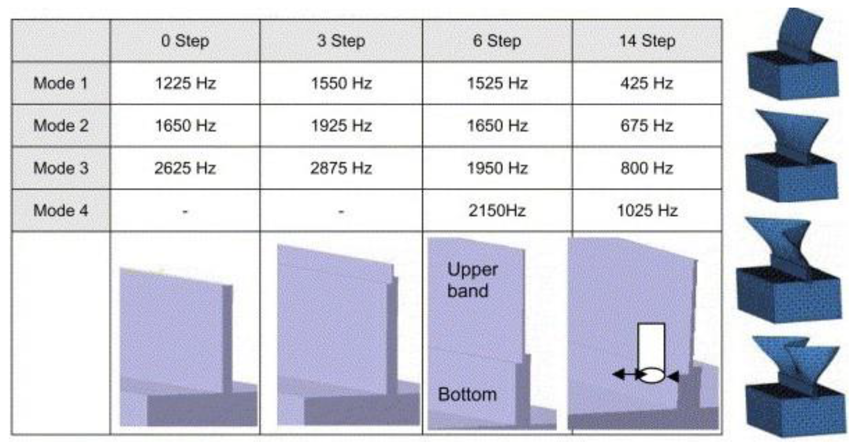
Figure 5.
The identification of dynamic characteristics by analytical method [20].
Figure 5.
The identification of dynamic characteristics by analytical method [20].
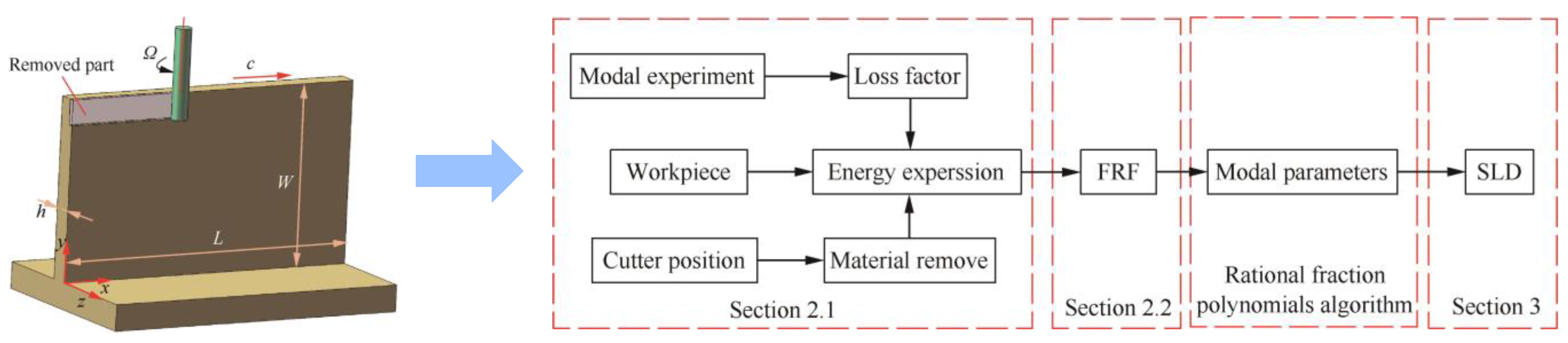
Figure 6.
FRFs prediction of in−process thin−walled part by FEMA with structural dynamic modification [34].
Figure 6.
FRFs prediction of in−process thin−walled part by FEMA with structural dynamic modification [34].

Figure 7.
Dynamic characteristics identification through cross−axis and cross−point modal testing [54]: (a) Dynamic model; (b) Model testing; (c) Schematic RSF sets for modal parameter identification.
Figure 7.
Dynamic characteristics identification through cross−axis and cross−point modal testing [54]: (a) Dynamic model; (b) Model testing; (c) Schematic RSF sets for modal parameter identification.

Figure 8.
FRF prediction of tool tip point using RCSA method [66].
Figure 8.
FRF prediction of tool tip point using RCSA method [66].

Figure 9.
The schematic diagram of dynamic models under different stiffness conditions: (a) relatively flexible cutter; (b) flexible cutter and workpiece; (c) relatively flexible workpiece.
Figure 9.
The schematic diagram of dynamic models under different stiffness conditions: (a) relatively flexible cutter; (b) flexible cutter and workpiece; (c) relatively flexible workpiece.

Figure 10.
Cutter–workpiece engagement extraction methods: (a) discrete modeling method [134]; (b) solid modeling method [132]; (c) CWE extraction considering the force−induced deformation [135].
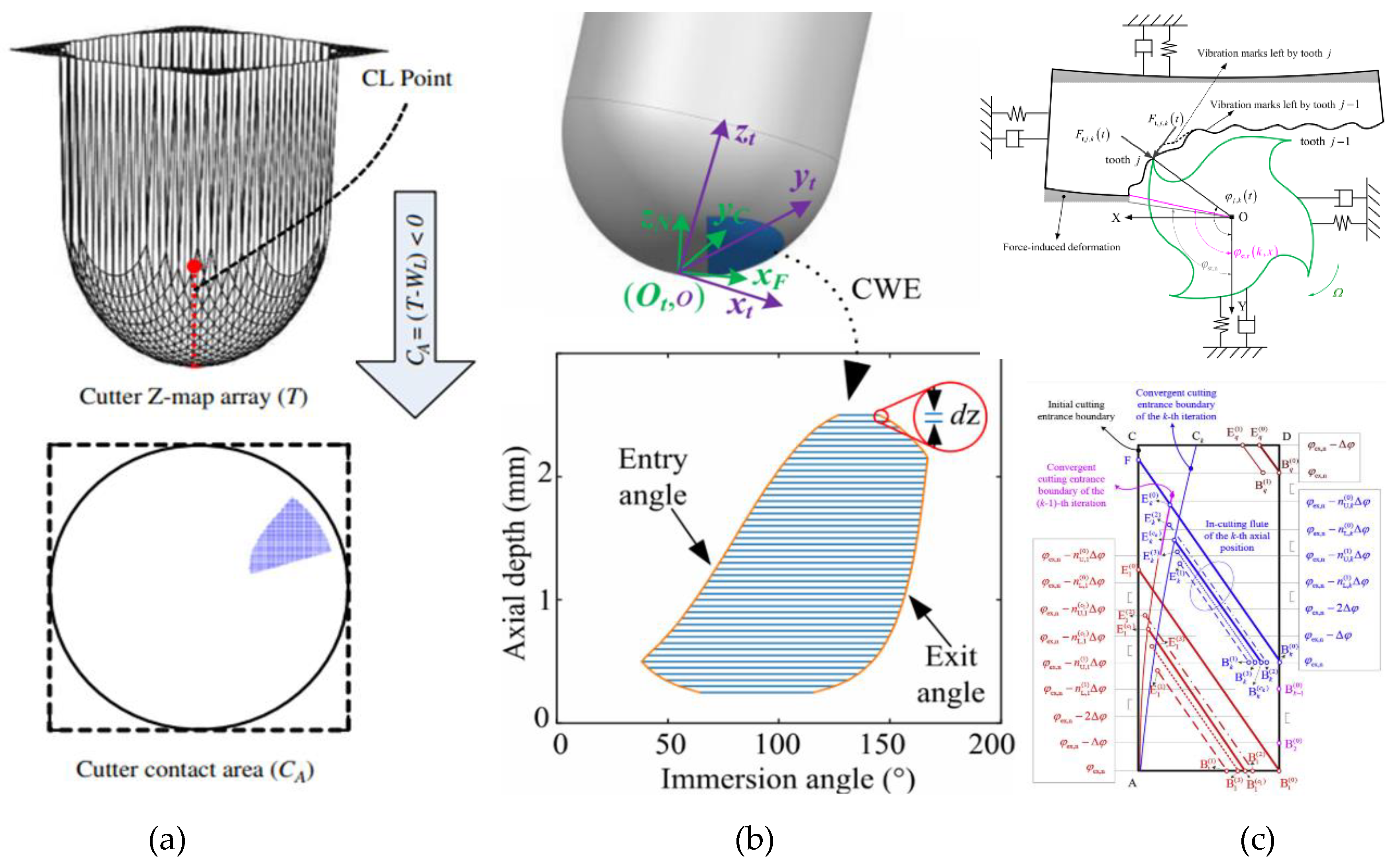
Figure 11.
Velocity−dependent process damping model in thin−walled milling [170]: (a) self−excited vibrations in milling process; (b) FRFs of workpiece; (c) 3D stability lobes with process damping.
Figure 11.
Velocity−dependent process damping model in thin−walled milling [170]: (a) self−excited vibrations in milling process; (b) FRFs of workpiece; (c) 3D stability lobes with process damping.
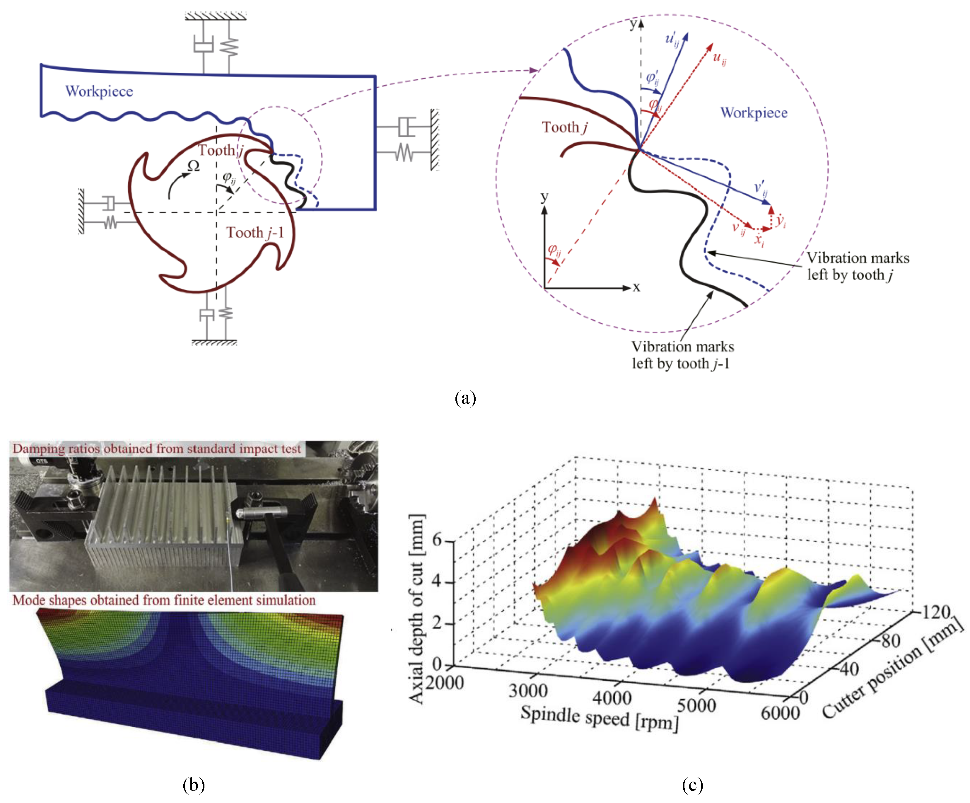
Figure 12.
Three kinds of stability prediction algorithms and their stability criteria.

Figure 13.
Classification of the chatter avoidance/suppression methods.
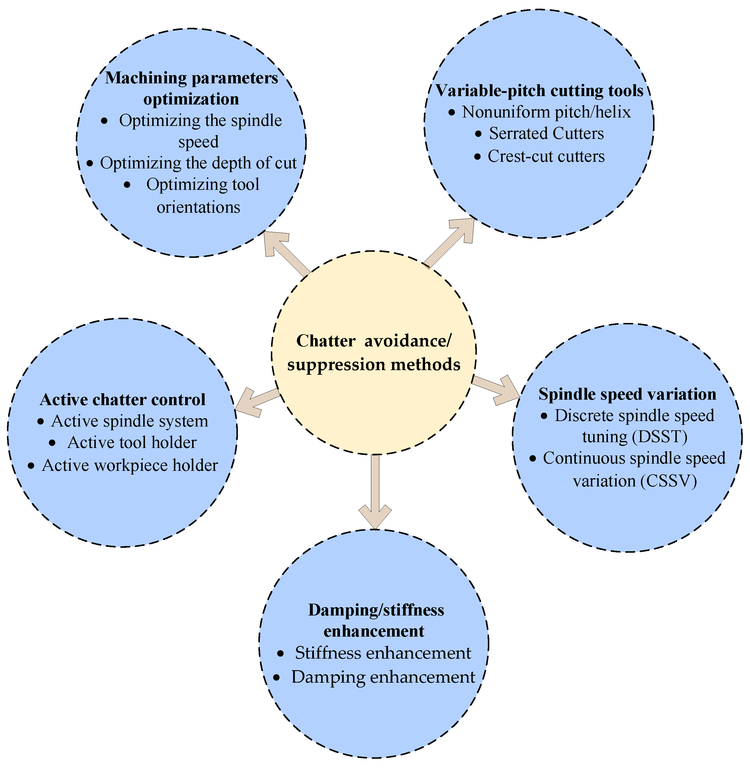
Figure 15.
Variable−geometry cutting tools for chatter suppression: (a) variable pitch tool; (b) variable helix tool; (c) serrated tool; (d) crest−cut tool.
Figure 15.
Variable−geometry cutting tools for chatter suppression: (a) variable pitch tool; (b) variable helix tool; (c) serrated tool; (d) crest−cut tool.

Figure 16.
Stability lobes and chatter test results for crest−cut end mill [248].
Figure 16.
Stability lobes and chatter test results for crest−cut end mill [248].

Figure 17.
Sinusoidal, triangular, and rectangular shape for spindle speed variation.

Figure 18.
Methods of damping/stiffness enhancement.
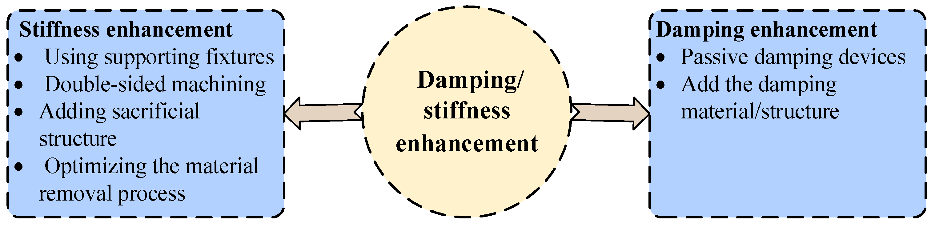
Figure 19.
Stiffness enhancement method: (a–d) Supporting fixtures for thin−wall machining [264,266,267,268]; (e–f) Double−sided machining [269,270].

Figure 20.
Stiffness enhancement method: (a) adding sacrificial structure [274]; (b) Stock thickness and shape selection [277].


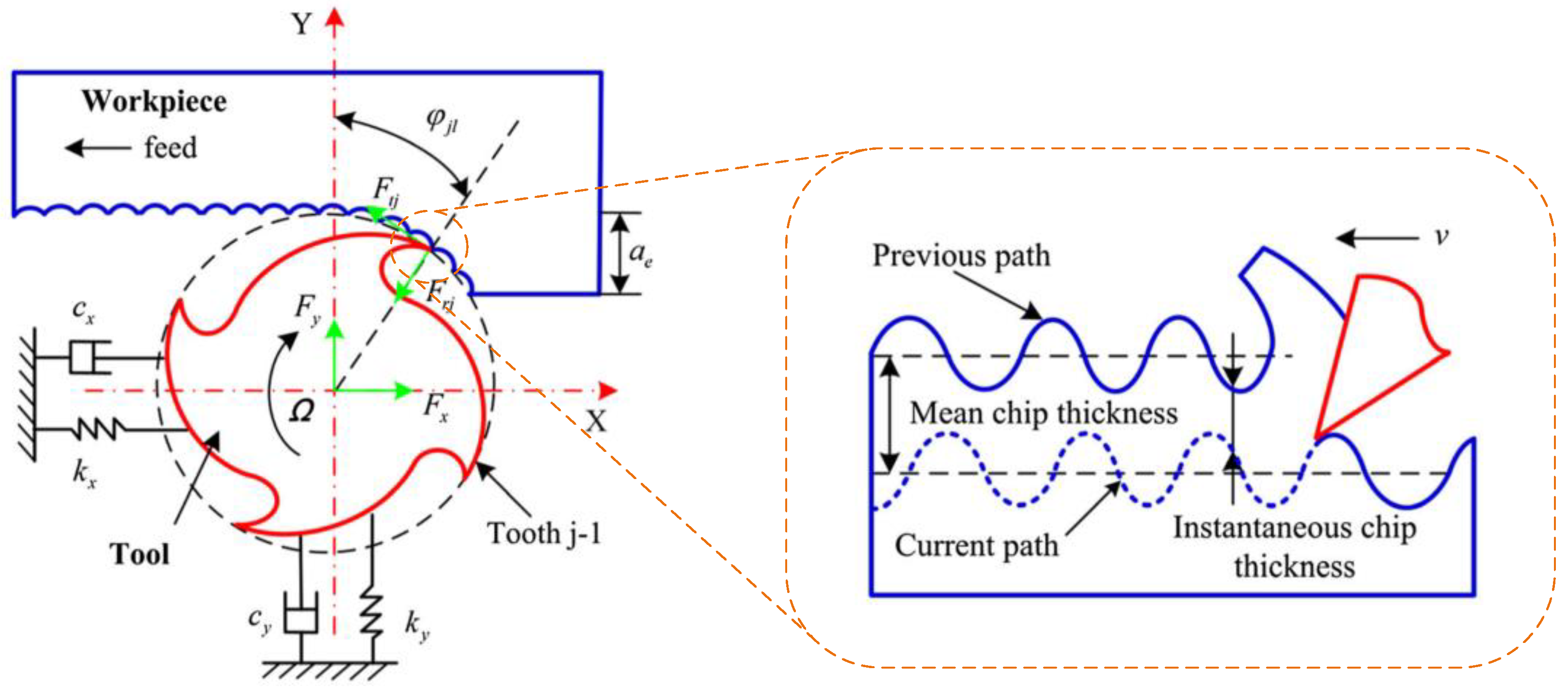
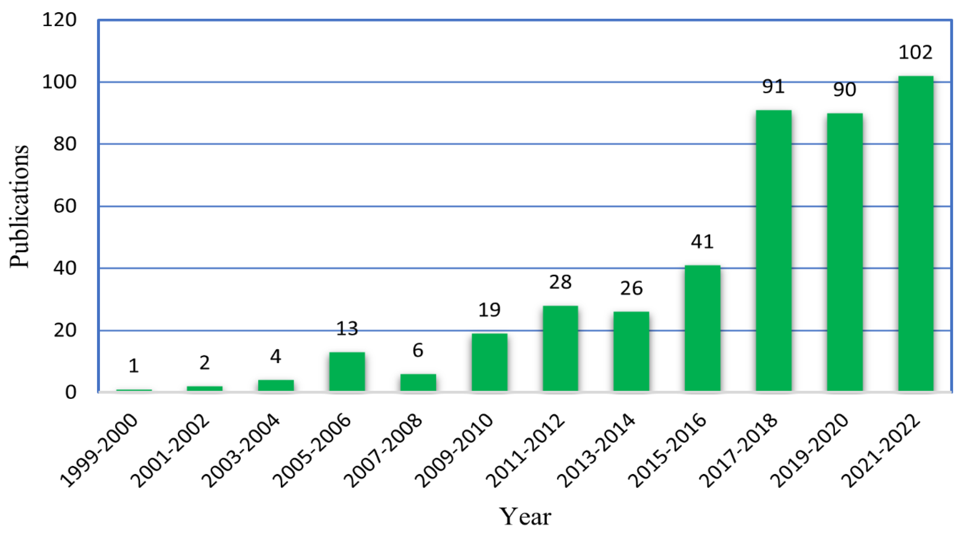
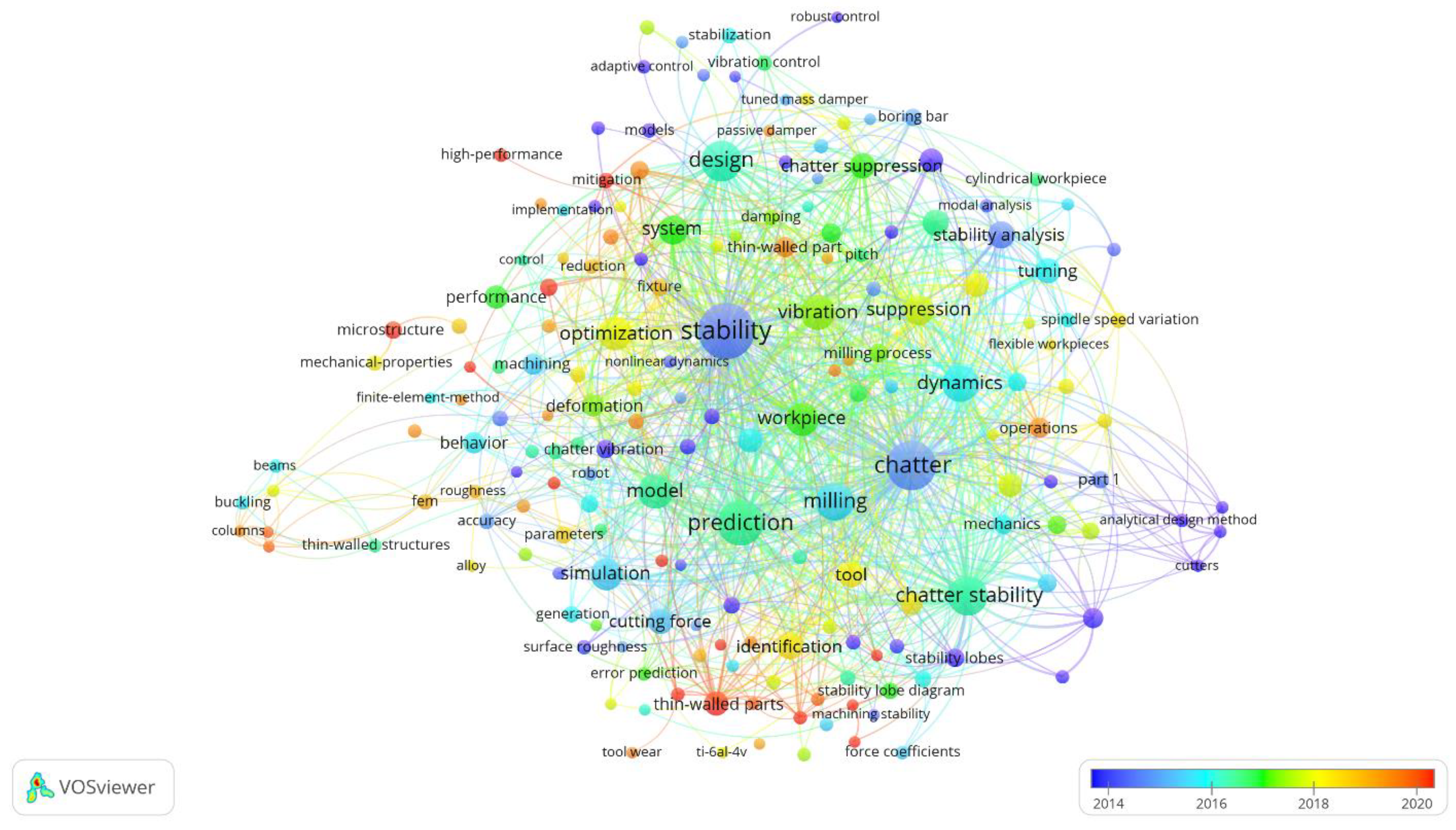
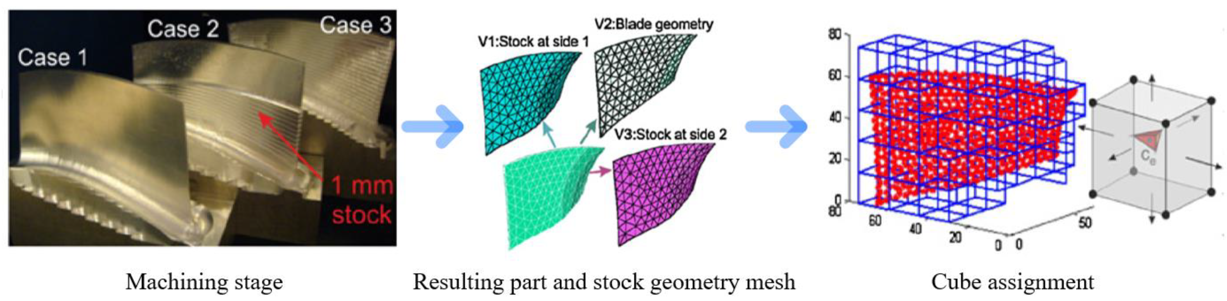
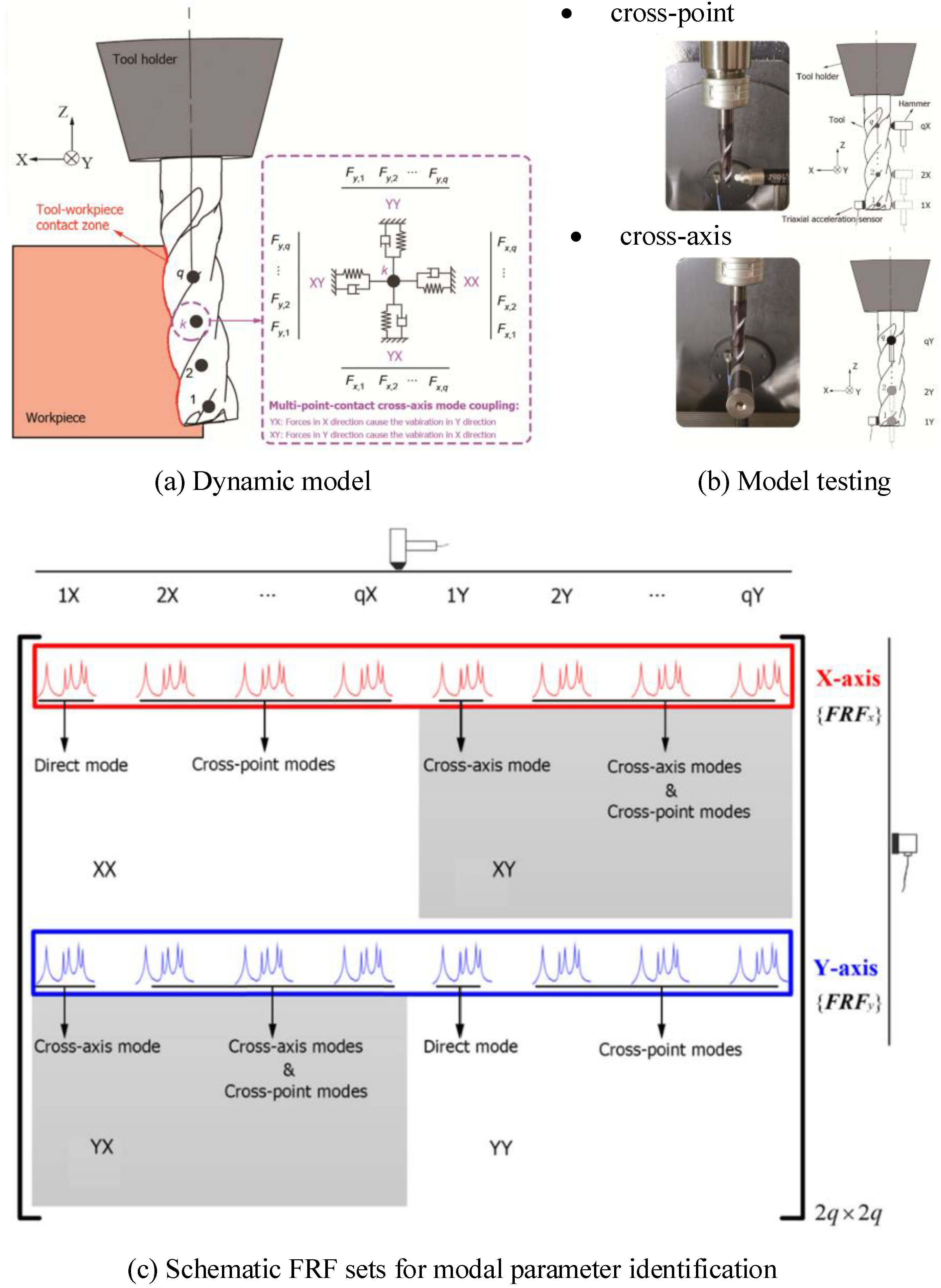
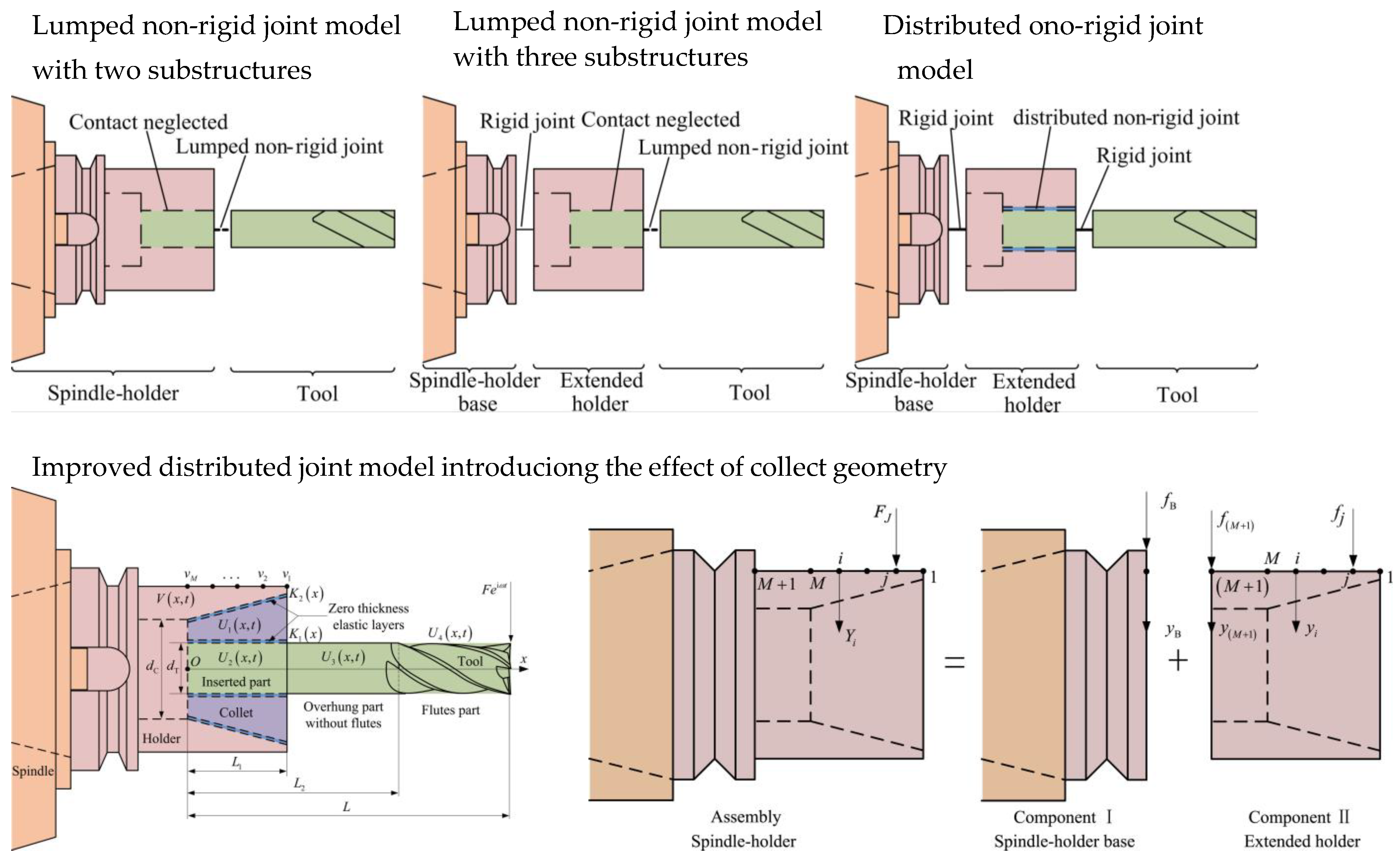
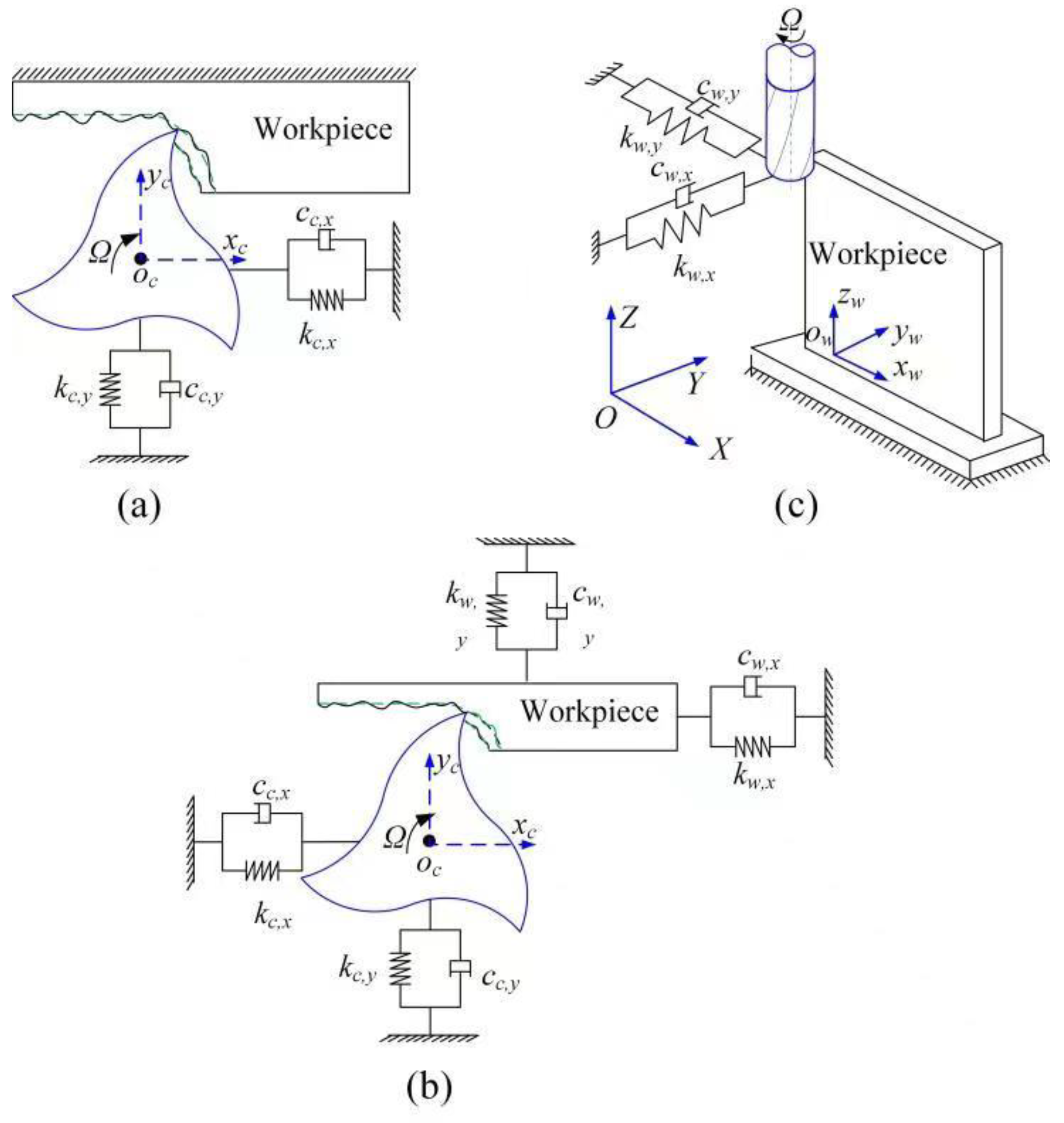
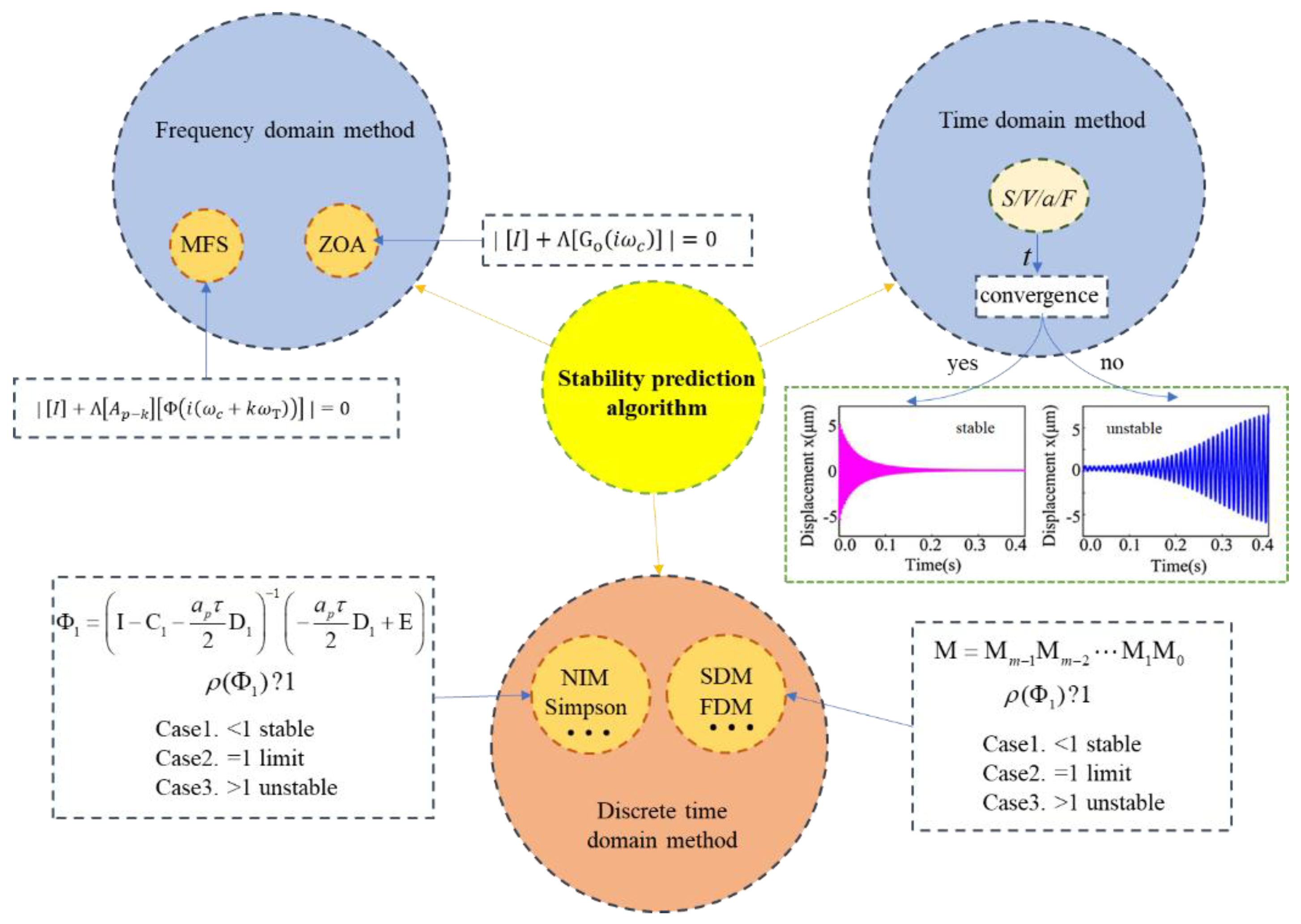
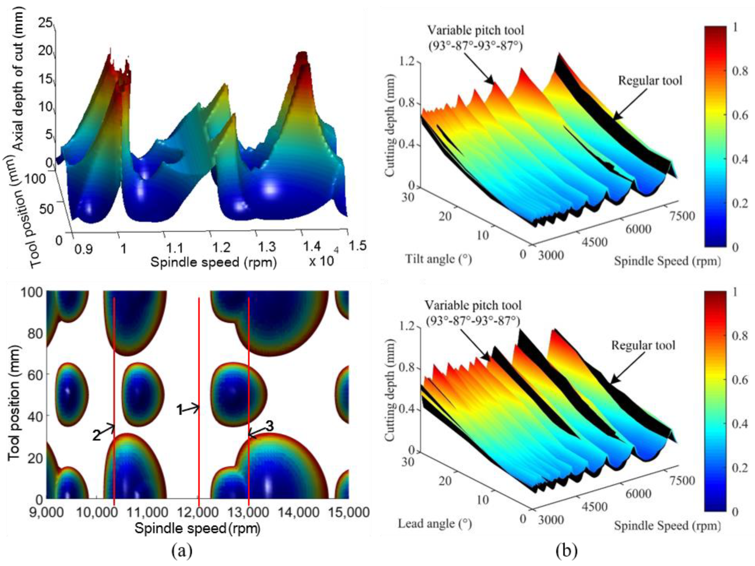
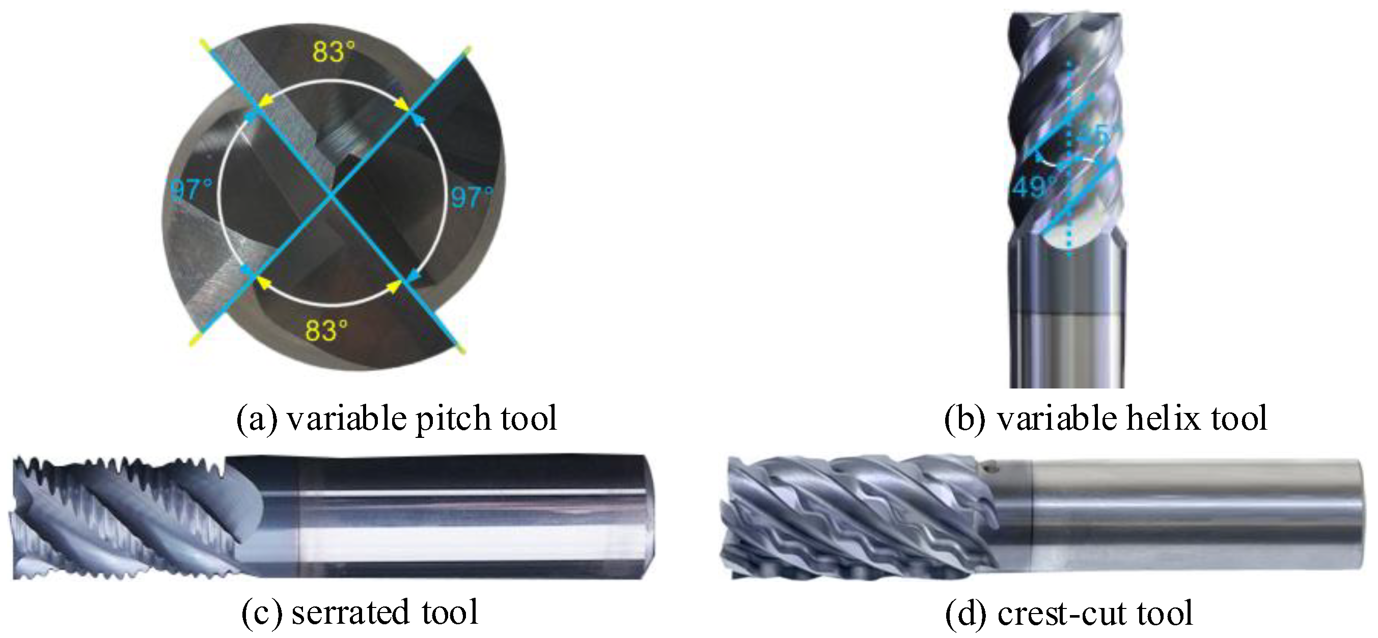
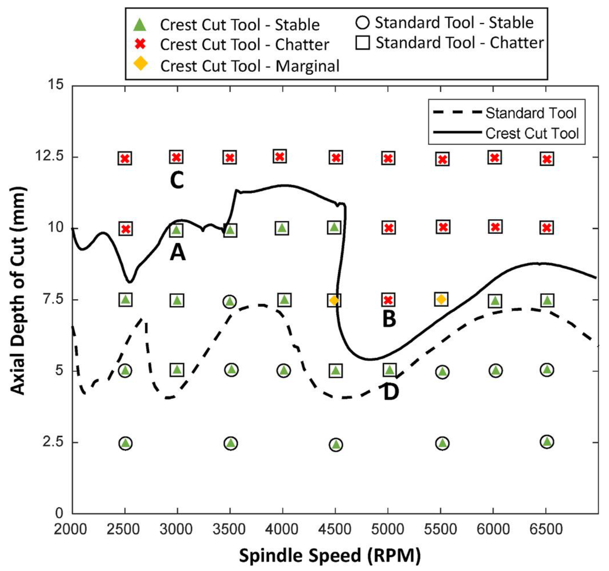
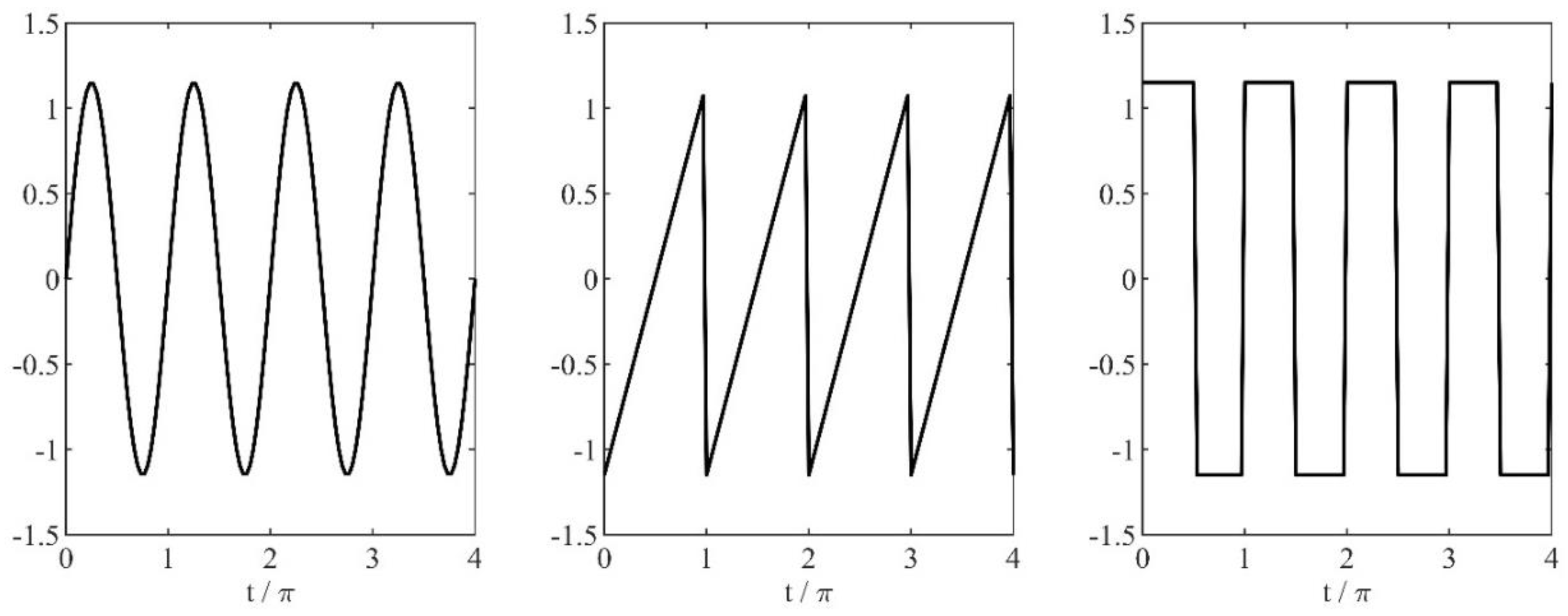
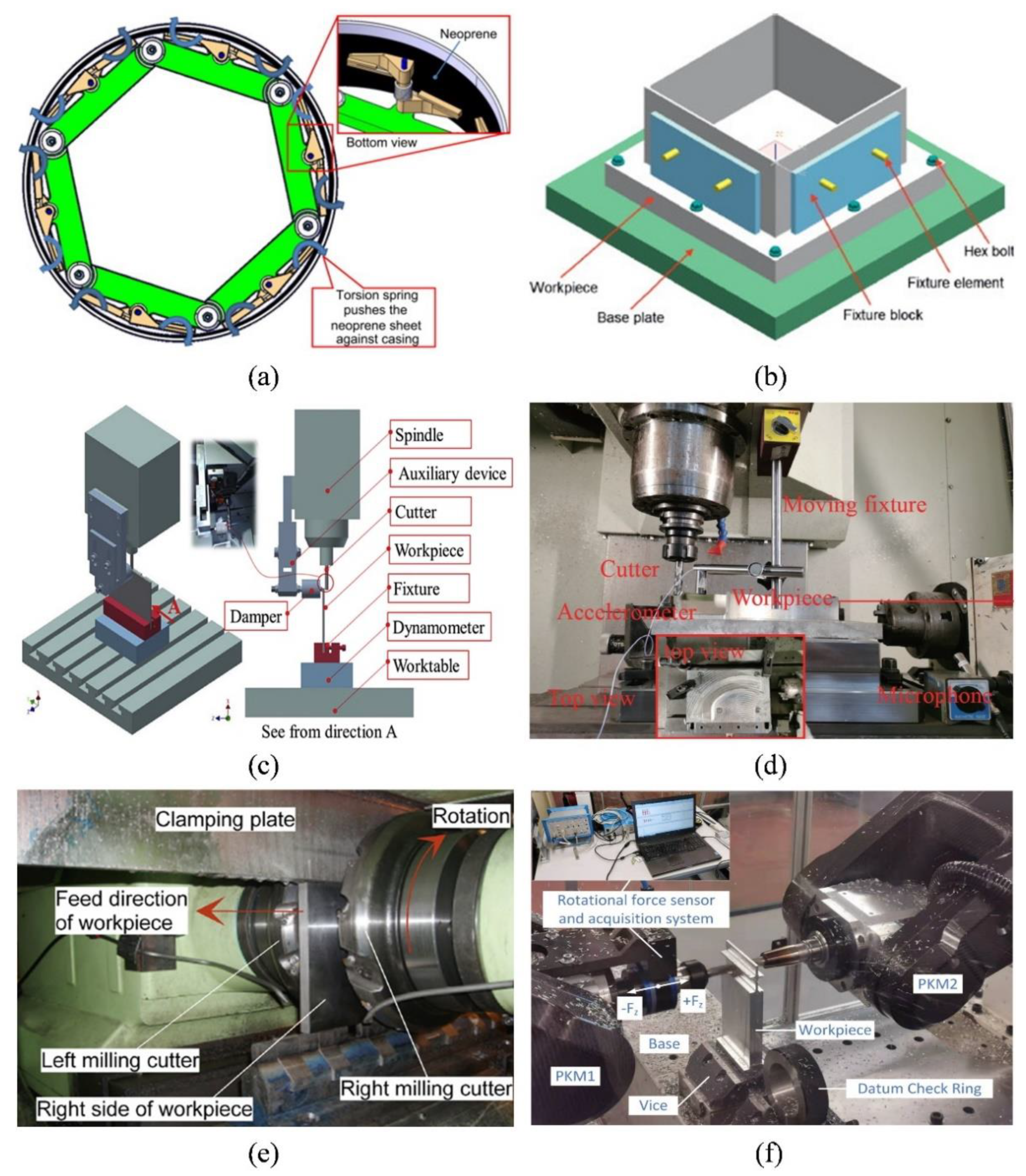
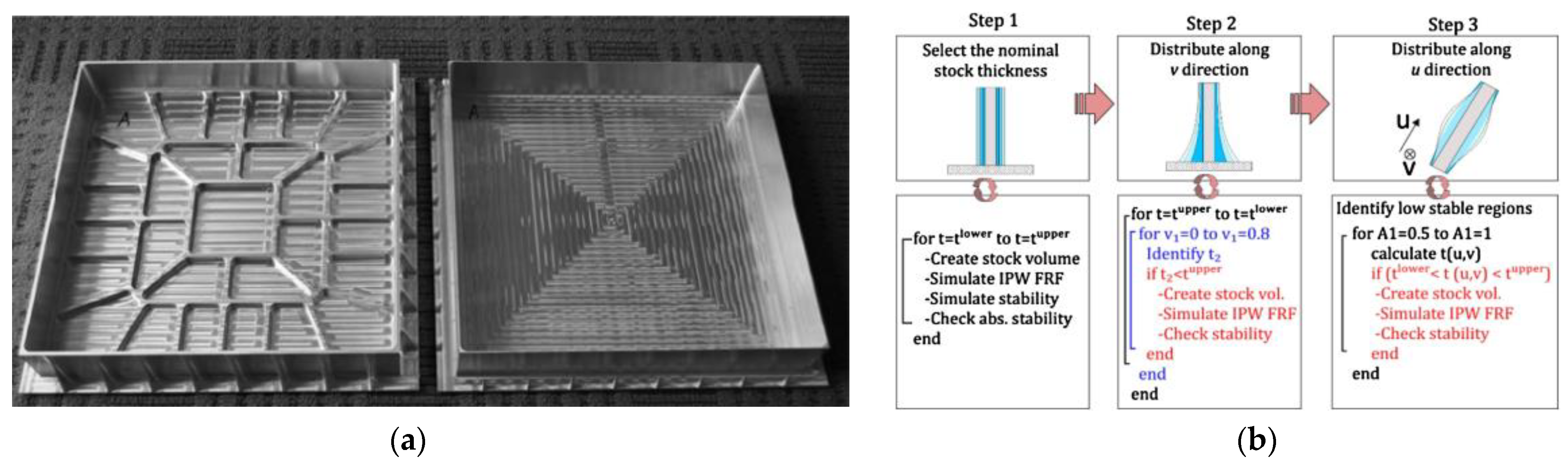
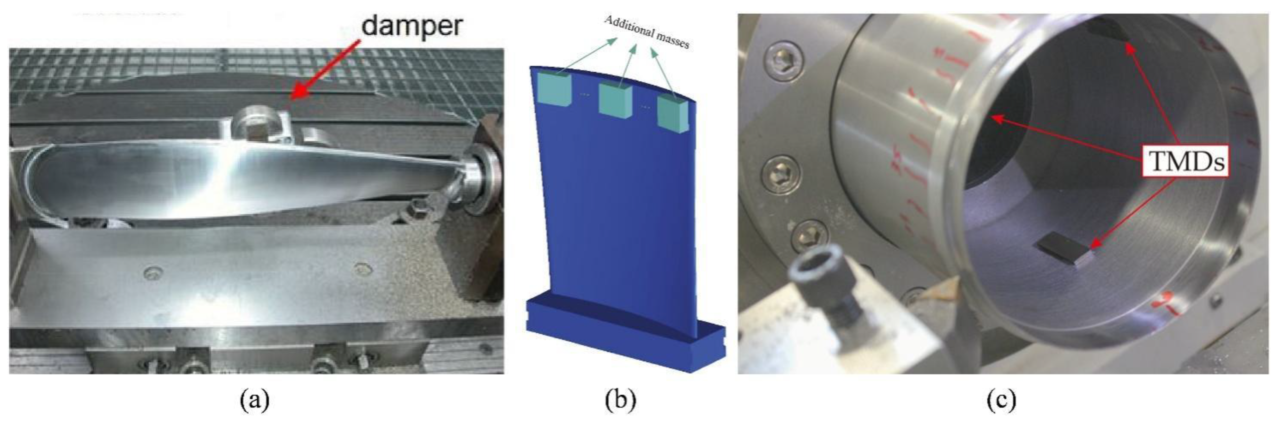
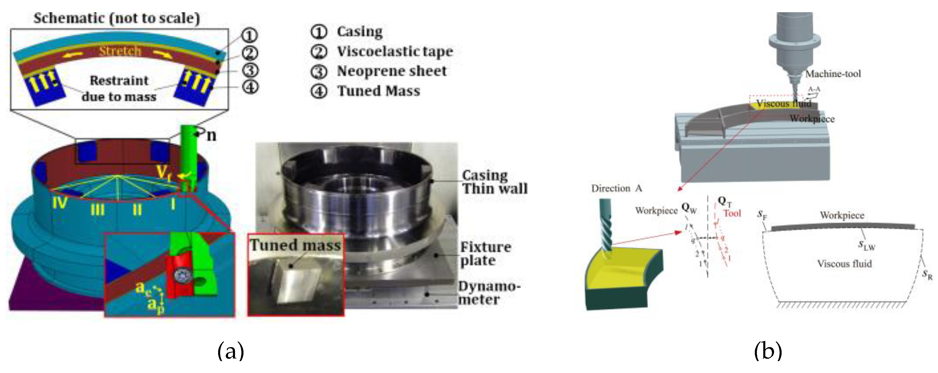
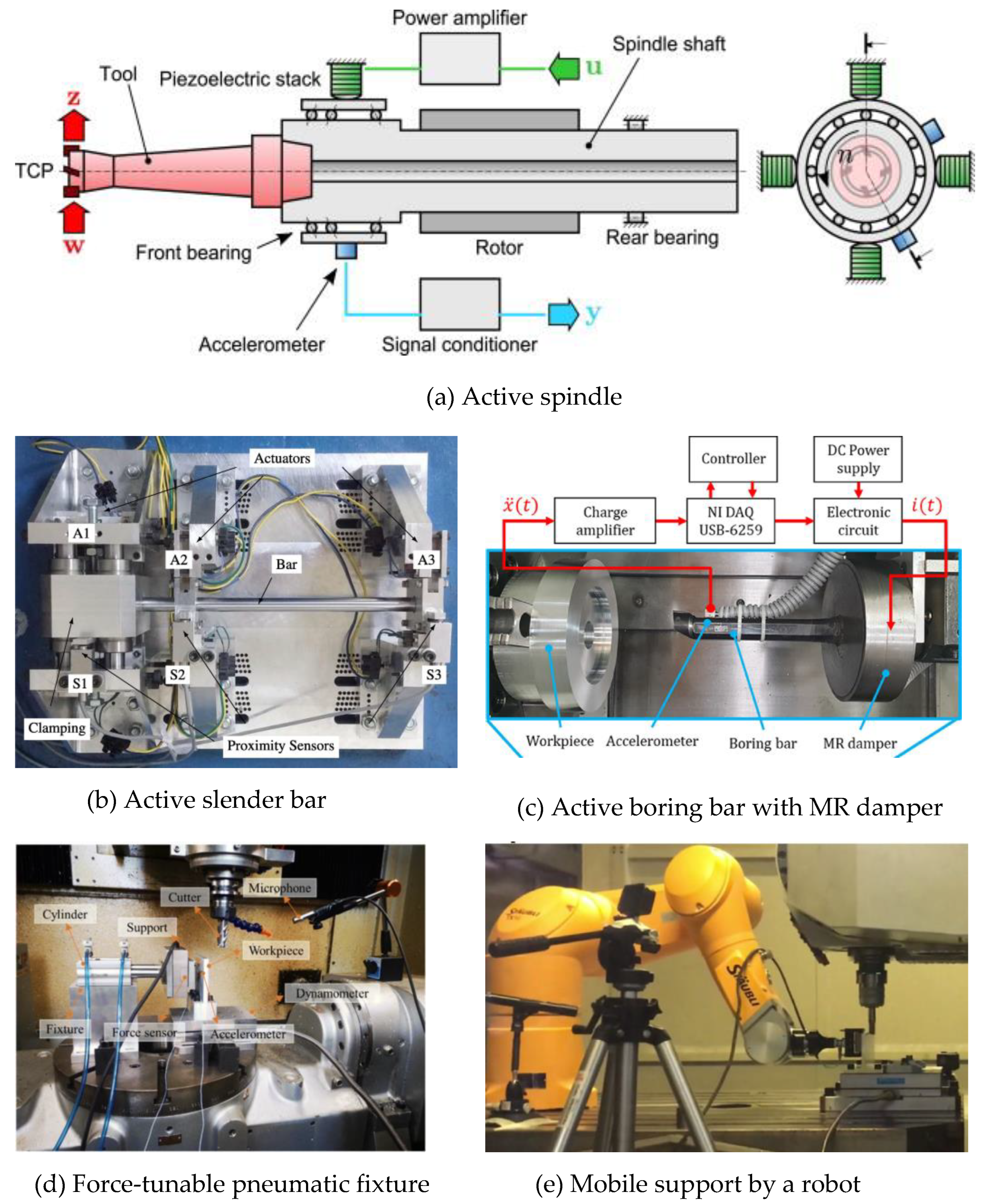
Disclaimer/Publisher’s Note: The statements, opinions and data contained in all publications are solely those of the individual author(s) and contributor(s) and not of MDPI and/or the editor(s). MDPI and/or the editor(s) disclaim responsibility for any injury to people or property resulting from any ideas, methods, instructions or products referred to in the content. |
© 2023 by the authors. Licensee MDPI, Basel, Switzerland. This article is an open access article distributed under the terms and conditions of the Creative Commons Attribution (CC BY) license (https://creativecommons.org/licenses/by/4.0/).
Share and Cite
MDPI and ACS Style
Sun, Y.; Zheng, M.; Jiang, S.; Zhan, D.; Wang, R. A State-of-the-Art Review on Chatter Stability in Machining Thin−Walled Parts. Machines 2023, 11, 359. https://doi.org/10.3390/machines11030359
AMA Style
Sun Y, Zheng M, Jiang S, Zhan D, Wang R. A State-of-the-Art Review on Chatter Stability in Machining Thin−Walled Parts. Machines. 2023; 11(3):359. https://doi.org/10.3390/machines11030359
Chicago/Turabian StyleSun, Yuwen, Meng Zheng, Shanglei Jiang, Danian Zhan, and Ruoqi Wang. 2023. "A State-of-the-Art Review on Chatter Stability in Machining Thin−Walled Parts" Machines 11, no. 3: 359. https://doi.org/10.3390/machines11030359
Note that from the first issue of 2016, this journal uses article numbers instead of page numbers. See further details here.