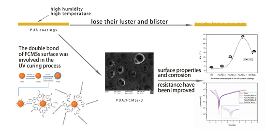
UV-Curable Hydrophobic Coatings of Functionalized Carbon Microspheres with Good Mechanical Properties and Corrosion Resistance

 ,
,
Abstract
:
1. Introduction
2. Materials and Methods
2.1. Materials
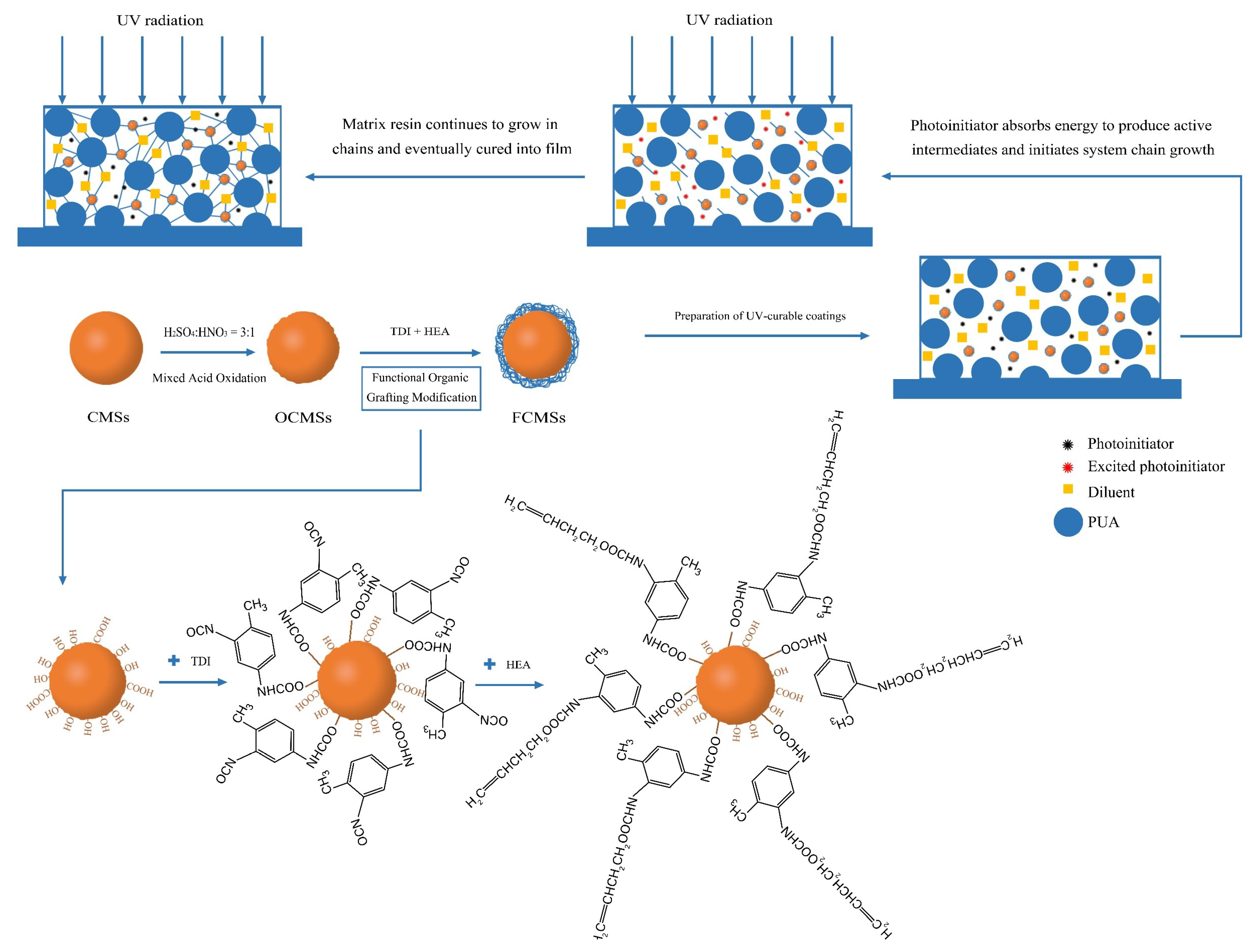
2.2. Preparation of Carbon Microspheres
2.3. Organic Modification of OCMSs
2.4. Preparation of UV-Curable Coatings
2.5. Determination of Gel Rate of Cured Coatings
2.6. Determination of Water Absorption
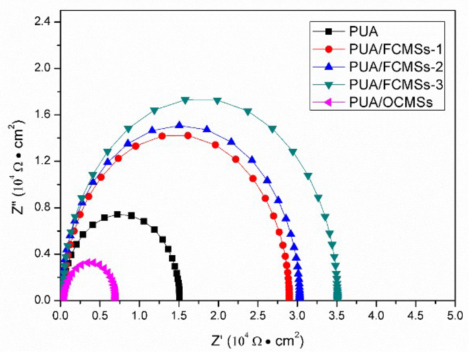
2.7. Determination of Corrosion Resistance
2.8. Characterization
3. Results and Discussion
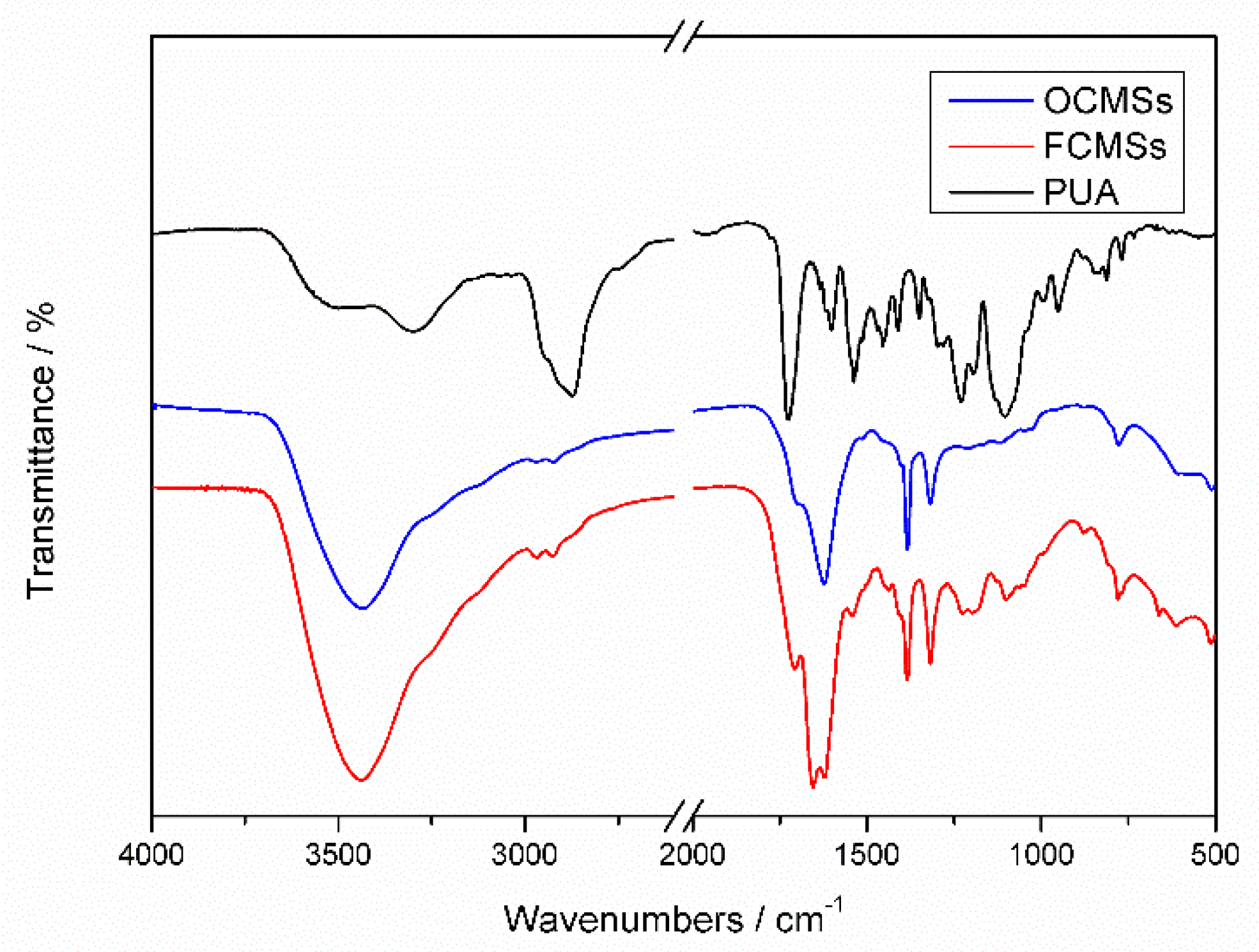
3.1. FTIR Results Analysis
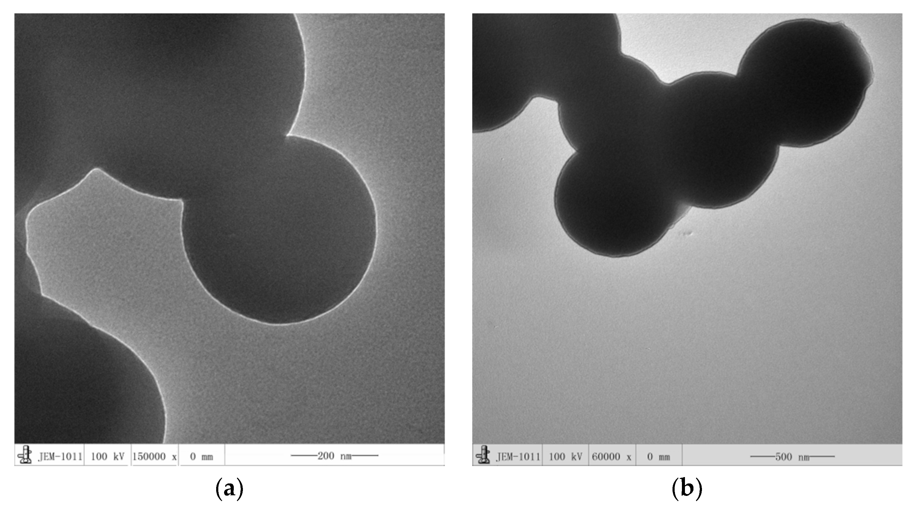
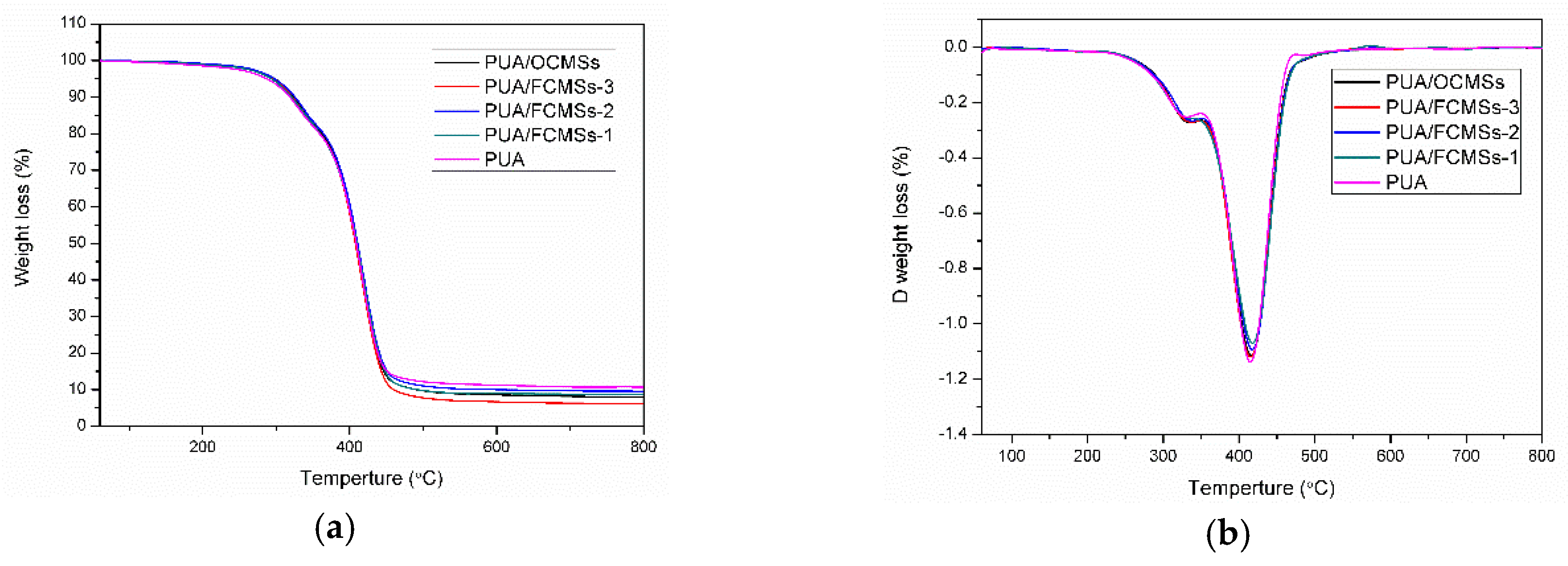
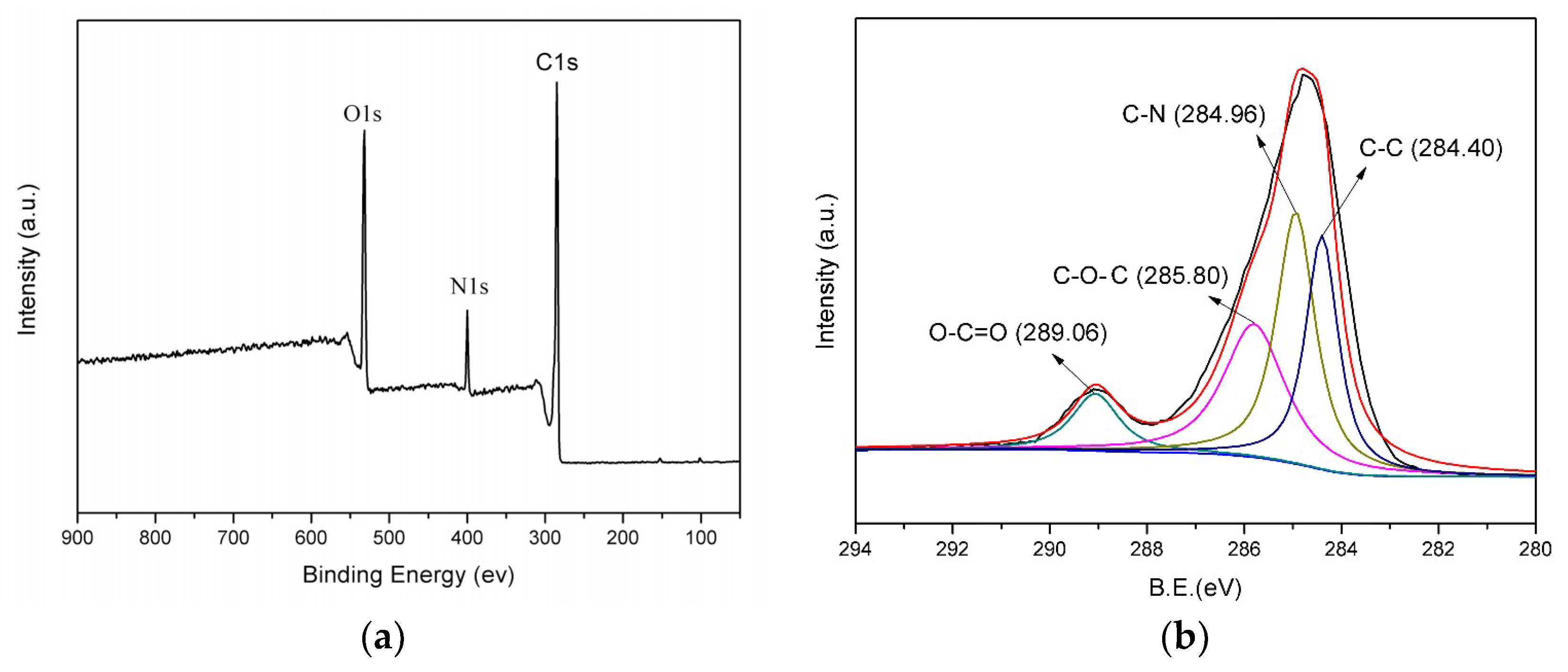
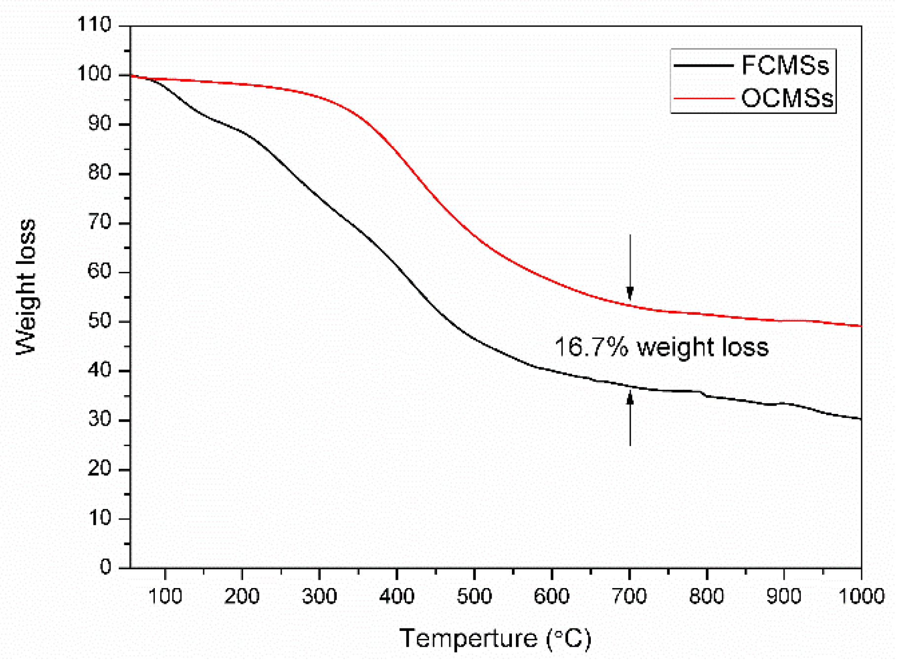
3.2. Analysis and Results of TEM, XPS and TG of OCMSs and FCMSs
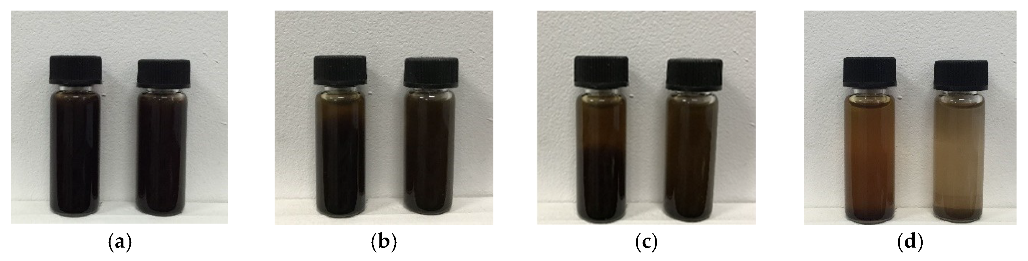
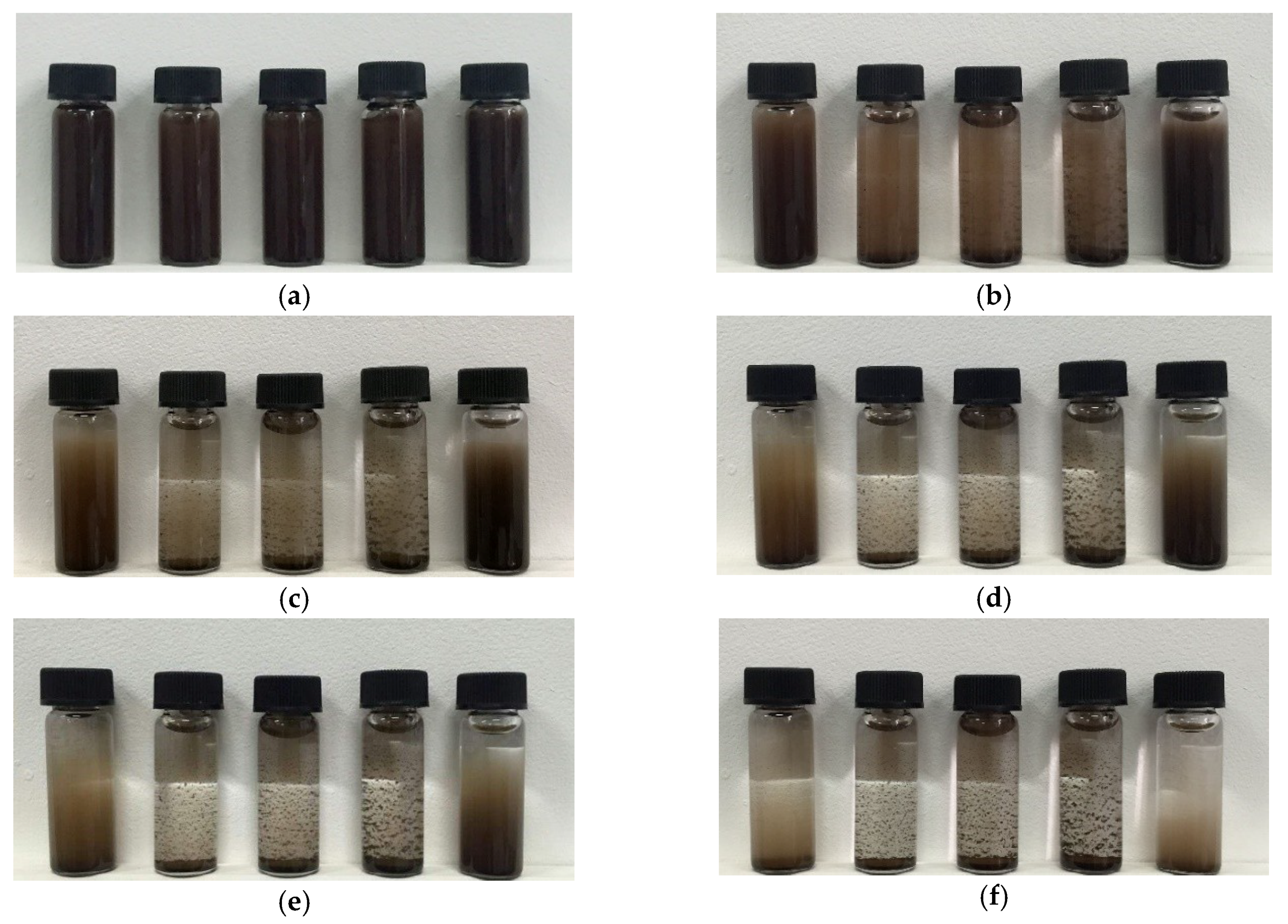
3.3. Study on the Dispersion of Carbon Microspheres in Solvent
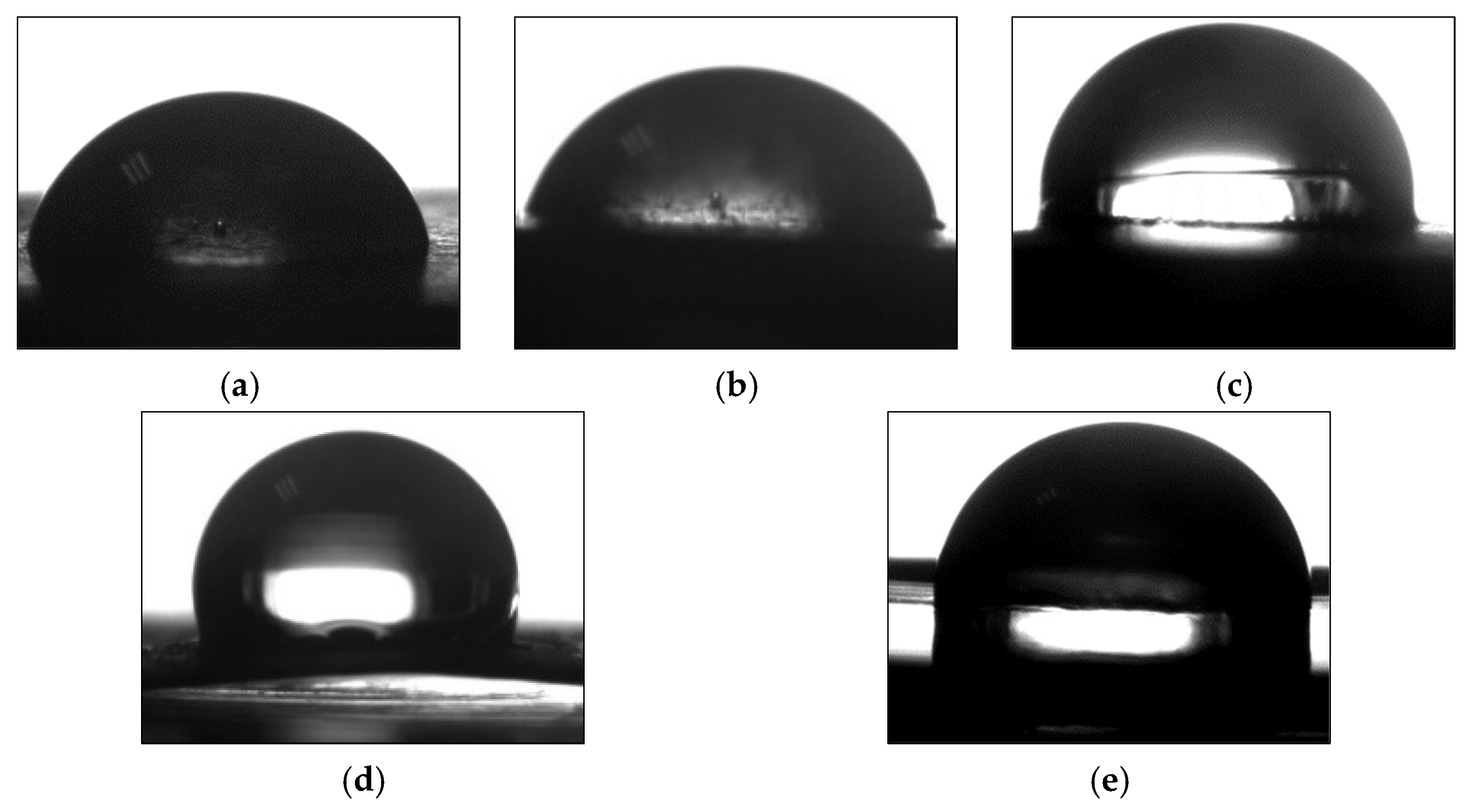
3.4. Performance of UV-Curable Coatings
4. Conclusions
Author Contributions
Funding
Acknowledgments
Conflicts of Interest
References
- Yan, X.X.; Qian, X.Y.; Lu, R.; Miyakoshi, T. Synergistic Effect of Addition of Fillers on Properties of Interior Waterborne UV-Curing Wood Coatings. Coatings 2018, 8, 9. [Google Scholar] [CrossRef]
- Yang, Z.L.; Douglas, A.W.; Charles, E.H.; Pu, H.T.; Yuan, J.J.; Wan, D.C.; Liu, Y.S. Newly UV-curable polyurethane coatings prepared by multifunctional thiol- and ene-terminated polyurethane aqueous dispersions mixtures: Preparation and characterization. Polymer 2009, 7, 1717–1722. [Google Scholar] [CrossRef]
- Dong, F.; Maganty, S.; Meschter, S.J.; Cho, J. Effects of curing conditions on structural evolution and mechanical properties of UV-curable polyurethane acrylate coatings. Prog. Org. Coat. 2018, 114, 58–67. [Google Scholar] [CrossRef]
- Zhang, T.; Wu, W.J.; Wang, X.J.; Mu, Y.P. Effect of average functionality on properties of UV-curable waterborne polyurethane-acrylate. Prog. Org. Coat. 2010, 68, 201–207. [Google Scholar] [CrossRef]
- Li, Y.Y.; Yang, Z.Z.; Qiu, H.X.; Zheng, Q.B.; Li, J.; Yang, J.H. Self-aligned graphene as anticorrosive barrier in waterborne polyurethane composite coatings. J. Mater. Chem. A. 2014, 2, 14139–14145. [Google Scholar] [CrossRef]
- Tsai, P.Y.; Chen, T.E.; Lee, Y.L. Development and Characterization of Anticorrosion and Antifriction Properties for High Performance Polyurethane/Graphene Composite Coatings. Coatings 2018, 8, 250. [Google Scholar] [CrossRef]
- Estekhraji, S.A.Z.; Amiri, S. Synthesis and Characterization of Anti-fungus; Anti-corrosion and Self-cleaning Hybrid Nanocomposite Coatings Based on Sol–Gel Process. J. Inorg. Organomet. Polym. 2017, 27, 883–891. [Google Scholar] [CrossRef]
- Ma, I.A.W.; ShRamesh, A.K.; Vengadaesvaran, B.; Ramesh, S.; Arof, A.K. Anticorrosion Properties of Epoxy-Nanochitosan Nanocomposite Coating. Bioresources 2017, 12, 2912–2929. [Google Scholar] [CrossRef]
- Atta, A.M.; El-Saeed, A.M.; Al-Lohedan, H.A.; Wahby, M. Effect of Montmorillonite Nanogel Composite Fillers on the Protection Performance of Epoxy Coatings on Steel Pipelines. Molecules 2017, 22, 905. [Google Scholar] [CrossRef] [PubMed]
- Purcar, V.; Şomoghi, R.; Niţu, S.G.; Nicolae, C.A.; Alexandrescu, E.; Gîfu, I.C.; Gabor, A.R.; Stroescu, H.; Ianchiş, R.; Căprărescu, S.; et al. The Effect of Different Coupling Agents on Nano-ZnO Materials Obtained via the Sol–Gel Process. Nanomaterials 2017, 7, 439. [Google Scholar] [CrossRef] [PubMed]
- Wang, N.; Diao, X.L.; Zhang, J.; Kang, P. Corrosion Resistance of Waterborne Epoxy Coatings by Incorporation of Dopamine Treated Mesoporous-TiO2 Particles. Coatings 2018, 8, 209. [Google Scholar] [CrossRef]
- Yan, T.N.; Xu, J.L.; Chu, Z.Y.; Liu, E.H.; Yang, L.; Wang, C.H. Hydrothermal Synthesis and Electrochemical Properties of N-doped Activated Carbon Microspheres. Int. J. Electrochem. Sci. 2017, 6118–6128. [Google Scholar] [CrossRef]
- Ma, A.L.; Wang, X.M.; Li, T.B.; Liu, X.G.; Xu, B.S. Characteristics of carbon microspheres and study on its adsorption isotherms. Mater. Sci. Eng. A 2007, 443, 54–59. [Google Scholar] [CrossRef]
- Sun, B.F.; Li, H.L.; Li, X.Y.; Liu, X.W.; Zhang, C.H.; Xu, H.Y.; Zhao, X.S. Degradation of Organic Dyes over Fenton-like Cu2O-Cu/C Catalyst. Ind. Eng. Chem. Res. 2018, 57, 14011–14021. [Google Scholar] [CrossRef]
- Sun, X.M.; Li, Y.D. Colloidal carbon spheres and their core/shell structures with noble-metal nanoparticles. Angew. Chem. Int. Ed. 2004, 43, 597–601. [Google Scholar] [CrossRef] [PubMed]
- Zheng, M.T.; Liu, Y.L.; Xiao, Y.; Zhu, Y.; Guan, Q.; Yuan, D.S.; Zhang, J.X. An Easy Catalyst-Free Hydrothermal Method to Prepare Monodisperse Carbon Microspheres on a Large Scale. J. Phys. Chem. C. 2009, 113, 8455–8459. [Google Scholar] [CrossRef]
- Ryu, G.; Suh, Y.W.; Dong, J.S.; Dong, J.A. Hydrothermal preparation of carbon microspheres from mono-saccharides and phenolic compound. Carbon 2010, 48, 1990–1998. [Google Scholar] [CrossRef]
- Kumar, S.; Kothari, U.; Kong, L.Z.; Lee, Y.Y.; Guptanl, R.B. Hydrothermal pretreatment of switchgrass and corn stover for production of ethanol and carbon microspheres. Biomass Bioenerg. 2011, 35, 956–968. [Google Scholar] [CrossRef]
- Gong, Y.T.; Xie, L.; Li, H.; Wang, Y. Sustainable and scalable production of monodisperse and highly uniform colloidal carbonaceous spheres using sodium polyacrylate as the dispersant. Chem. Commun. 2014, 50, 12633–12636. [Google Scholar] [CrossRef] [PubMed]
- Gan, L.; Geng, A.B.; Xu, L.J.; Chen, M.J.; Wang, L.C.; Liu, J.; Han, S.G.; Mei, C.T.; Zhong, Q. The fabrication of bio-renewable and recyclable cellulose based carbon microspheres incorporated by CoFe2O4 and the photocatalytic properties. J. Cleaner Prod. 2018, 196, 594–603. [Google Scholar] [CrossRef]
- Titirici, M.M.; Antonietti, M. Chemistry and materials options of sustainable carbon materials made by hydrothermal carbonization. Chem. Soc. Rev. 2010, 39, 103–116. [Google Scholar] [CrossRef] [PubMed]
- Wen, J.J.; Li, H.J.; Liu, X.H.; Huang, C.; Li, H.B. Organic modification of silica and its application in polyurethane acrylate coatings. Packag. J. 2017, 9, 42–497. (In Chinese) [Google Scholar]
- Wen, J.J.; Wang, D.; Liu, X.H.; Huang, C.; Li, H.B. Synthesis and properties of UV-curable polyurethane acrylate coatings. Packag. J. 2017, 9, 65–71. (In Chinese) [Google Scholar] [CrossRef]
- Zhang, Q.Y.; Huang, C.; Wang, H.X.; Hu, M.J.; Li, H.B.; Liu, X.H. UV-curable coating crosslinked by a novel hyperbranched polyurethane acrylate with excellent mechanical properties and hardness. RSC Adv. 2016, 6, 107942–107950. [Google Scholar] [CrossRef]
- Lv, C.H.; Hu, L.; Yang, Y.; Li, H.B.; Huang, C.; Liu, X.H. Waterborne UV-curable polyurethane acrylate/silica nanocomposites for thermochromic coatings. RSC Adv. 2015, 5, 25730–25737. [Google Scholar] [CrossRef]
- Liu, R.; Zhang, X.P.; Zhu, J.J.; Liu, X.Y.; Wang, Z.; Yan, J.L. UV-Curable Coatings from Multiarmed Cardanol-Based Acrylate Oligomers. ACS Sustain. Chem. Eng. 2015, 3, 1313–1320. [Google Scholar] [CrossRef]


| Samples | T5% (°C) | T50% (°C) | Tmax1 (°C) | Tmax2 (°C) | GR (%) | WR (%) | WCA (°) | Pencil Hardness |
|---|---|---|---|---|---|---|---|---|
| PUA | 285 | 409 | 329 | 415 | 94 | 52 | 72 | H |
| PUA/FCMSs-1 | 293 | 410 | 343 | 418 | 99 | 30 | 73 | 2H |
| PUA/FCMSs-2 | 297 | 411 | 338 | 418 | 99 | 33 | 83 | 3H |
| PUA/FCMSs-3 | 294 | 408 | 338 | 415 | 98 | 38 | 106 | 4H |
| PUA/OCMSs | 298 | 409 | 335 | 417 | 95 | 37 | 89 | 4H |
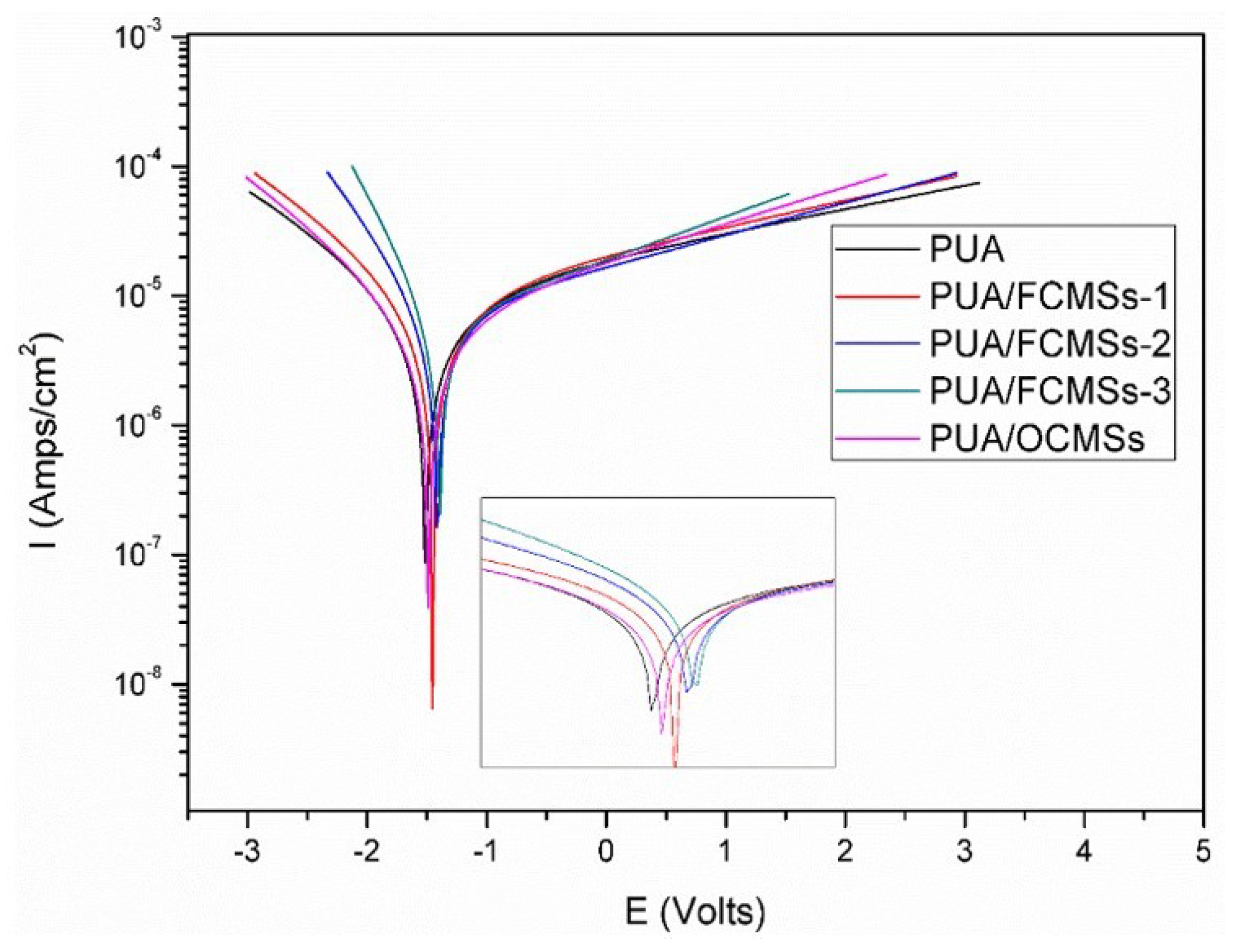
| Samples | Icorr (Amp cm−2) | E0 (V) | Vcorr (mm/a) |
|---|---|---|---|
| PUA | 1.0550 × 10⁻⁵ | −1.5143 | 0.124 |
| PUA/FCMSs-1 | 1.0340 × 10⁻⁵ | −1.4525 | 0.106 |
| PUA/FCMSs-2 | 7.4238 × 10⁻⁶ | −1.4139 | 0.087 |
| PUA/FCMSs-3 | 6.5122 × 10⁻⁶ | −1.3959 | 0.076 |
| PUA/OCMSs | 6.9574 × 10⁻⁶ | −1.4873 | 0.082 |
© 2018 by the authors. Licensee MDPI, Basel, Switzerland. This article is an open access article distributed under the terms and conditions of the Creative Commons Attribution (CC BY) license (http://creativecommons.org/licenses/by/4.0/).
Share and Cite
Wen, J.; Feng, C.; Li, H.; Liu, X.; Ding, F.; Li, H.; Huang, C. UV-Curable Hydrophobic Coatings of Functionalized Carbon Microspheres with Good Mechanical Properties and Corrosion Resistance. Coatings 2018, 8, 439. https://doi.org/10.3390/coatings8120439
Wen J, Feng C, Li H, Liu X, Ding F, Li H, Huang C. UV-Curable Hydrophobic Coatings of Functionalized Carbon Microspheres with Good Mechanical Properties and Corrosion Resistance. Coatings. 2018; 8(12):439. https://doi.org/10.3390/coatings8120439
Chicago/Turabian StyleWen, Jiajia, Chengchen Feng, Huijie Li, Xinghai Liu, Fuyuan Ding, Houbin Li, and Chi Huang. 2018. "UV-Curable Hydrophobic Coatings of Functionalized Carbon Microspheres with Good Mechanical Properties and Corrosion Resistance" Coatings 8, no. 12: 439. https://doi.org/10.3390/coatings8120439