1. Introduction
Due to the decades old technology scaling predicted by Moore’s law, sequential elements are becoming increasingly susceptible to soft errors as operating voltages and parasitic capacitances are reduced. Traditionally, concerns for these disruptions were limited to space applications but are now often considered in mission critical applications on Earth as well like bio-medical devices. Radiation strikes introduce charge on nodes within sequential elements like memory bits, latches and flip-flops and can result in data corruption if the charge collected on one of the internal nodes exceeds a critical charge level (Qcrit). Alternatively, an associated transient pulse can be induced on nodes in combinatorial or clock tree signals, which can result in faults if the pulse occurs within the limits of the setup/hold times of the related clock, but these effects are less predominant due to the damping of subsequent combinatorial circuits.
The sensitivity to radiation is more predominant for low voltage electronics in which the amount of charge required to induce a failure is reduced linearly not only with the node capacitance but also the supply voltage as
Qnode = Cnode ×
Vdd [
1]. Furthermore, many power-conscious applications apply dynamic voltage scaling—alternating operation between high and low voltages—in order to optimize power and performance for a variety of workloads. Consequently, during periods of low activity at low supply voltages, these circuits are substantially more vulnerable to upsets from radiation.
Coincidentally, subthreshold logic has emerged as a technology that can deliver the theoretical minimum energy per computation (orders of magnitude less than contemporary CMOS) [
2]. Subthreshold circuits operate with a supply voltage that is less than the threshold of the transistor—below traditional levels—and as a result, the transistor operates essentially on leakage. While traditional digital CMOS has relied on running transistors either in the
on state (saturation) or
off state, subthreshold circuits switch between an
off state or an
almost-on state (still in the subthreshold regime but with weak inversion). Running at these non-standard operating points, severely restricts circuit performance, which may remain tolerable for low-to-medium cost applications based on the dramatic improvement in the energy efficiency or alternatively can be used as the low performance operating point for a dynamic voltage scaling scheme.
As power is related quadratically to the supply voltage, reducing the voltage to these ultra-low levels result in a dramatic reduction in both power and energy consumption in digital systems. However, this increased energy efficiency comes at the price of a substantial degradation of robustness in terms of
Qcrit. This paper proposes a novel SEU immune flip-flop design optimized for subthreshold operation, and although others have discussed guidelines for SRAM design to improve SEU in finFET subthreshold [
3] or have modeled the impact of soft errors for subthreshold circuits [
4], to the best of the authors’ knowledge, no other publication discusses a hardware characterization of soft error sensitivity for circuits intentionally operated at subthreshold levels.
The remainder of the article is organized as follows.
Section 2 discusses the existing published SEU immune flip-flop designs.
Section 3 describes a proposed flip-flop design and the guiding design principles that led to the improved energy delay product at subthreshold levels.
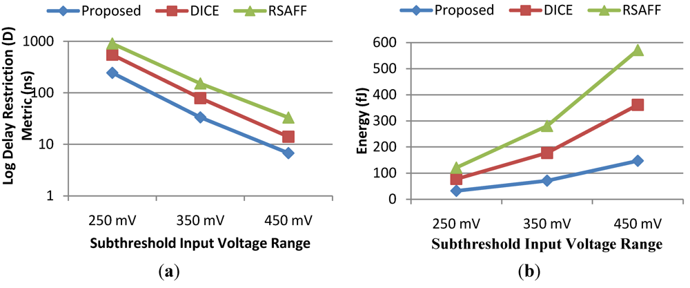
Section 4 reports the simulation methodology and results with regards to measuring performance and energy of all four designs. Additionally, the section discusses simulation results relating to measuring the radiation hardness of the designs used for the comparison.
Section 5 describes the fabricated hardware, the hardware setup, radiation details and the radiation results. Finally,
Section 6 provides the conclusion.
2. Previous Work
Although no study has performed a hardware comparison of flip-flops in the subthreshold regime in terms of radiation, a simulation comparison using models from IBM12SOI 45nm CMOS technology was performed in [
5] with an initial version of the proposed flip-flop. More generally, sequential elements have been examined in the traditional sense through simulations [
6,
7] over a wide cross section of commonly used flip-flops with a primary focus on performance and energy consumption. However, in addition to confining the comparisons to only conventional operating voltages, neither work considered the differences in radiation hardness between the cells. For applications in radiation environments like space electronics, robust flip-flops are essential for correct operation and many techniques have been proposed to provide radiation hardness. This study broadly classifies the techniques into three categories: (1) radiation hardened by redundancy; (2) radiation hardened by circuit design; and (3) radiation hardened by process. Popular implementations for the first category include either Dual Redundancy (DR) with Muller C-element or Triple Modular Redundancy (TMR) with majority voting [
8,
9]. DR uses full redundancy to detect errors, while TMR can detect and correct an error in case of a single event; however, both techniques incur a substantial penalty in power and delay due to the required redundancy and this work is confined to stand-alone rad-hard sequential elements that were hardened by circuit design and process. In [
10], a Single Event Transient (SET) suppressor technique was proposed that adjusts the clock edge timing such that flip-flops capture data only when in the correct state. However, this technique requires adjusting the clock at subthreshold levels may make the design unreliable given the exponential dependency on environmental variables of delay.
Radiation effects have historically been mitigated by process although many of the radiation-hardened technologies are either expensive or unavailable commercially. Silicon-On-Insulator (SOI) was originally used for space electronics based on the active devices being isolated from the substrate where the corrupting charge is generated during a radiation event [
1]. However, the SOI process was recognized in the 1990’s for providing other advantages in terms of power consumption and performance as the parasitic junction capacitances of the source/drain junctions were virtually eliminated. This improvement becomes even more pronounced as the voltage is reduced due to the reduction in the depletion region as the junctions are less reverse-biased. Consequently, this work focuses on a fully-depleted SOI process.
Two existing radiation-hardened designs were used for comparison in this work as well as a tradition textbook flip-flop implemented with tri-state inverters and which included no inherent radiation hardness. The rad-hard designs included the Dual Interlocked storage Cell (DICE) as an edge-triggered master-slave flip-flop [
11,
12,
13] and the Rad-hard Sense Amplifier Flip-Flop (RSAFF) [
14].
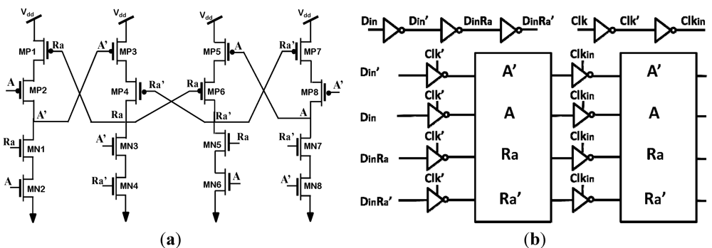
Figure 1 illustrates both designs, which are robust at superthreshold voltage levels; however, in subthreshold—where transistors operate in the weak inversion region with reduced drive strength—the feedback path is feeble and may not be sufficient to overcome the charge introduced by the radiation event. Nonetheless, the increased sensitivity to radiation at subthreshold voltages is unacceptable as failures become exponentially more probable, and consequently, rad-hard techniques should be incorporated to mitigate upsets.
2.1. Dual Interlocked Cell (DICE) Based Flip-Flop Design
The DICE design operates on the principle of
dual node feedback control to achieve upset immunity [
11,
12,
13]. The logic state of the four nodes of the cell is controlled by two feedback nodes located on the previous stage. The DICE design used for the analysis is the clocked inverter latch version of DICE and is suggested to provide reduced power dissipation and is suitable for master and slave sections of an edge-triggered flip-flop circuit. By interweaving two pairs of redundant nodes (data and data bar) within the cell, this rad-hard design is reduced in transistor count relative to full dual redundancy of the traditional design. Whereas the traditional flip-flop with tri-state inverters has 24 transistors and the fully redundant design has 48, the DICE design shares a similar architecture but includes only 40 transistors.
2.2. Rad-Hard Sense-Amplifier Based Flip-Flop Design
Typically, sense-amplifier flip-flops are used to provide high performance in digital systems at the expense of increased power consumption. To date, no study has comprehensively evaluated rad-hard sense-amplifier flip-flops at subthreshold voltages. The sense-amplifier design considered in this analysis is a modified version of the traditional sense-amplifier flip-flop and includes radiation hardness. The Rad-hard Sense Amplifier Flip-Flop (RSAFF) consists of a sense amplifier-based master stage, a middle stage with four NOR-gates and a slave stage with a modified SR-latch. [
14] RSAFF provides upset immunity due to redundant node storage and claims immunity to Transient Faults (TF) due to the delayed latching action between the SR-latch and the NOR-gates. Furthermore, [
14] argued that the RSAFF is the best existing design by describing a Transient Fault Window of Vulnerability (TFWOV) affecting the alternative DICE cell.
Figure 1.
Existing radiation hardened flip-flop designs. (
a) Dual Interlocked storage Cell (DICE) latch used to design an edge triggered master-slave flip-flop [
11,
12,
13]; (
b) Rad-hard Sense-Amplifier based Flip-Flop (RSAFF) [
14].
Figure 1.
Existing radiation hardened flip-flop designs. (
a) Dual Interlocked storage Cell (DICE) latch used to design an edge triggered master-slave flip-flop [
11,
12,
13]; (
b) Rad-hard Sense-Amplifier based Flip-Flop (RSAFF) [
14].
3. Proposed Design
The proposed rad-hard flip-flop is an edge-triggered master-slave type, consisting of two rad-hard latches. Each latch is designed such that redundant data is stored at two different nodes and provides a feedback path in order to recover after a single event upset or transient. The overriding design principle used to generate the subthreshold-optimized design included limiting the transistor stacking to no more than two transistors as highly stacked configurations compound the reduced drive strength in subthreshold.
Figure 2 illustrates the resulting latch. Redundant nodes are intertwined while maintaining minimum transistor stacking. Although the RSAFF provides the minimal clock input capacitance relative to the proposed design, the limited stacking shown in
Figure 2(a) provides a subthreshold performance advantage relative to the RSAFF, which includes stacking of three transistors in the first stage. The DICE has minimum transistor stacking also, but the proposed design avoids the TFWOV issue afflicting the DICE.
Figure 2.
Proposed rad-hard design (a) transistor-level latch and (b) full flip-flop design.
Figure 2.
Proposed rad-hard design (a) transistor-level latch and (b) full flip-flop design.
4. Simulations
Although the proposed and existing designs were fabricated using the XLP technology, a processing issue resulted in dramatically increased resistances in well diffusion resistors. Consequently, resistors used in the Input/Output (IO) circuits to protect against Electro-Static Discharge (ESD) prevented accurate measurements of the performance and power of each of the four flip-flops. Fortunately, the issue did not affect the flip-flop designs directly and functionality remained intact—allowing for dynamic radiation hardness testing albeit at reduced frequency to accommodate the higher input resistances. Consequently, the performance and power consumption of the four designs were compared through simulations with XLP models and only the soft error analysis in this article is based on hardware.
4.2. Radiation Sensitivity
Beyond performance and efficiency, radiation hardness was captured as
Qcrit—measured as the charge required to flip a bit and was simulated by inserting a current source between the (victim) internal node and ground [
16]. For the
Qcrit analysis, a double exponential current source with a peak corresponding to the funneling charge collection and a slowly decaying tail for the diffusion charge collection was adopted [
17]. The rise time constant for charge collection at the junction and a fall time constant for the ion track are dependent on the process technology of the devices. Typically,
Qcrit is proportional to the operating voltage, particle Linear Energy Transfer (LET) and the effective collection depth. In silicon, the deposited charge is roughly 10 fC per µm of the track length for a particle having an LET of 1 MeV-cm
2/mg [
18,
19].
The
Qcrit was measured by varying the magnitude of the current spike while the time constants were held constant for the above configuration to introduce varying amounts of charge into the vulnerable node. For each design, all susceptible nodes were identified and a radiation strike was simulated. Both polarities were tested for all vulnerable nodes and
Table 3 shows the
Qcrit values for each rad-hard design. In comparison, the non-hardened flip-flop was corrupted at only 32 fC of
Qcrit charge with the same models and conditions.
For single event transient analysis, an external charge of 20 fC and 100 fC for subthreshold and superthreshold was injected into the master latch internal node during a clock transition and a TFWOV—if existing—was measured as described in [
20]. For the above analysis, the proposed flip-flop demonstrated correct operation at levels of injected charge as high as 150 fC and the RSAFF performed similarly well. However, the DICE cell demonstrated the vulnerability and was therefore eliminated from serious consideration as a viable design option based on the demonstrated TFWOV. However, the design is included in all comparisons for completeness.
Table 3 illustrates the
Qcrit and TFWOV values for sub and superthreshold values for all four designs. As the radiation hardened flip-flop designs considered in this analysis are immune to single event upset at superthreshold, they are indicated as Not Affected (N/A). However, at subthreshold all flip-flops have the potential to fail but with dramatically improved values of
Qcrit relative to the traditional, non-hardened design. The proposed flip-flop provides 25% improved
Qcrit relative to the RSAFF at 250 mV and a 66% improvement in
Qcrit as compared to the DICE flip-flop. The reason for the improvement in
Qcrit for the proposed design can be explained by the minimized transistor stacking which improves the drive strength of the circuit responsible to remove the introduced charge.
Table 3.
Flip-flop Qcrit and Transient Fault Window of Vulnerability (TFWOV) values for a variety of supply voltages.
Table 3.
Flip-flop Qcrit and Transient Fault Window of Vulnerability (TFWOV) values for a variety of supply voltages.
| | 0.25 V | 0.35 V | 0.45 V | 1.5 V |
|---|
| Qcrit (fC) | TFWOV | Qcrit (fC) | TFWOV | Qcrit (fC) | TFWOV | Qcrit (fC) | TFWOV |
| Traditional | 2 | 135 nS | 6 | 53 nS | 10 | 43 nS | 80 | 12 nS |
| DICE | 45 | 110 nS | 55 | 15 nS | 62 | 800 pS | N/A | 175 pS |
| RSAFF | 60 | N/A | 75 | N/A | 100 | N/A | N/A | N/A |
| Proposed | 75 | N/A | 125 | N/A | 200 | N/A | N/A | N/A |
5. Fabricated Hardware and Heavy Ion Characterization
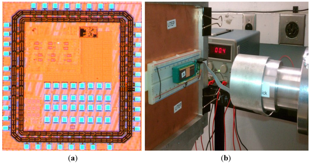
All four flip-flops were fabricated with the XLP process and
Figure 4(a) illustrates the die photo which includes the four designs and other unrelated experiments. Hardware characterization for the fabricated chips was limited to the radiation experiment. A processing problem resulted in increased resistance on Electro Static Discharge (ESD) resistors and consequently accurate performance and power results could not be measured. However, the flip-flop designs were unaffected and did function correctly albeit at a reduced frequency to accommodate the increased RC constant from the inputs of the chip. Given that each of the four designs could correctly store values and be read and written from reliably, a study was conducted with heavy ions to check for soft error rates. A test setup was developed that would write and read alternating data and report an error when a discrepancy was detected. The setup was run for several days continuously prior to the radiation experiment in order to prove that the test setup was reliable and would not introduce false failures. Millions of cycles were recorded without incident. A serial connection was used to report data in real time to a control computer located in the data room above the radiation chamber. Two-way communications were used to read the data as well as to control the supply voltage used by the flip-flops with the choice of two selectable voltages (450 mV and 1.5 V) to change between sub and superthreshold operation during the irradiation. The control and powering electronics were not in the radiation beam and thus worked reliably during the study.
Figure 4(b) illustrates the test setup in which taped lids were removed and the breadboard was placed inches from the source. The control and communications electronics was approximately 16 inches to the side connected through a ribbon cable including all flip-flop signals. A serial cable with DB9 connectors of approximately 40 feet was used to communicate with the control room computer that collected the data at a robust baud rate of 2400. An eight-hour slot was contracted with the Cyclotron Institute at Texas A&M University to gain access to a variety of heavy ion beams using a 15 MeV/u beam. For each of the different beams, the parameters of LET, fluence and cycles of testing are shown in
Table 4. Initially, Neon was used to provide a small LET of 2.8 MeV-cm
2/mg. As described in
Table 4, at the lower voltage, the traditional flip-flop immediately began to fail as expected given the low
Qcrit and the absence of radiation protection. Even at the standard voltage of 1.5 V, the traditional flip-flop continued to fail but at a substantially improved rate relative to the subthreshold operation as shown in
Table 4. However, none of the other rad-hard sequential cells failed for this low value of LET at either sub or superthreshold levels. Subsequently, several additional species were used including Argon, Copper and Silver—each with increasingly larger LET values (as described in
Table 4), which resulted in more charge generation with each particle strike. However, an unexpected impact of the larger ions was a substantial reduction in the maximum flux produced based on the limitations of the cyclotron. This reduction meant that fewer particles (by a factor of over 10) were being irradiated per second. Consequently, even though the subsequent beams of heavy ion particles transferred more energy per particle, the probability of a strike in an active area was reduced dramatically based on the substantial reduction in particles for a given irradiation period. As a result, the failure results in
Table 4 counter-intuitively reflect fewer failures for the heavier particle beams simply because they produced fewer particles and thus fewer possible events—which are proportional to the fluence (number of total particles irradiated) for each beam as reported in
Table 4.
Figure 4.
(a) Test chip fabricated for soft error characterization and (b) Cyclotron setup.
Figure 4.
(a) Test chip fabricated for soft error characterization and (b) Cyclotron setup.
For Neon, with a high flux, sufficient particles were fired at the device under test to cause significant failures in the traditional flip-flop. The fact that the radiation hardened flip-flops did not fail was predicted from the simulations for this low LET. The dramatic failure of the traditional flip-flop at the subthreshold voltage was also predicted and the implications are profound with regards to the use of non-fault-tolerant flip-flops in subthreshold applications—not only in the presence of radiation but also in any noisy environments in which coupled noise could result in incorrect operation. At higher LET species, the absolute number of failures was reduced only as a result of reduced flux based on the limitation of the cyclotron and the limit in radiation time. The actual failures per particle ratio increased as expected. The radiation hardened cells continued to operate fault-free with the exception of the DICE, which experienced one failure during the heaviest ion irradiation—Silver. This failure is likely related to the Transient Fault Window of Vulnerability and the rad-hard status for this flip-flop is designated with “Yes *” to differentiate the cell with regards to this sensitivity. Only one of these failures was detected which seems reasonable as the DICE would require both a direct hit by a particle coincident with the period of vulnerability—the simultaneous occurrence of both being an even lower probability.
Table 4.
Heavy ion characterization results.
Table 4.
Heavy ion characterization results.
| Flip-flop | Rad-hard | Active Area (μm2) | Detected Failures |
|---|
| NeonLET = 2.8Fluence = 2.2 × 10¹⁰ Cycles = 140 k | ArgonLET = 10Fluence = 1.04 × 10¹⁰Cycles = 120 k | CopperLET = 20Fluence = 4.9 × 10⁸ Cycles = 80 k | SilverLET = 43.2Fluence = 2.3 × 10⁹ Cycles = 200 k |
|---|
| 0.45 V | 1.5 V | 0.45 V | 1.5 V | 0.45 V | 1.5 V | 0.45 V | 1.5 V |
|---|
| Traditional | No | 31 | 38 | 1 | 18 | 5 | 0 | 0 | 8 | 4 |
| DICE | Yes * | 43.4 | 0 | 0 | 0 | 0 | 0 | 0 | 1 | 0 |
| RSAFF | Yes | 47.3 | 0 | 0 | 0 | 0 | 0 | 0 | 0 | 0 |
| Proposed | Yes | 49.6 | 0 | 0 | 0 | 0 | 0 | 0 | 0 | 0 |
6. Conclusions
This paper has presented a new design for radiation-hardened flip-flop that was fabricated in MIT Lincoln Lab’s XLP 0.15u fully-depleted CMOS process—specifically optimized for subthreshold operation. The proposed flip-flop was further optimized for subthreshold operation by design for input levels ranging from 250 to 450 mV based on limiting transistor stacking. The proposed cell was simulated and assessed for critical charge, power consumption and delay using HPSICE simulations. While both the proposed design and RSAFF were shown to be TFWOV resilient for all simulated voltages, at 250 mV, the proposed design provided an approximate 20% improvement in Qcrit and a 49.8% improvement in energy delay product when compared to the RSAFF design. Finally, the fabricated devices were subjected to heavy ion radiation to compare the existing radiation hardened designs with the proposed design at sub and superthreshold levels. To best of the authors’ knowledge, this work is the first to report hardware results of soft error experiments at such low voltages, and as predicted in simulations, the dramatic failure rate of the non-hardened design makes a powerful statement about the need for additional fault tolerance for circuits that operates in subthreshold—for both space and terrestrial applications. The analysis also illustrated that radiation can be successfully mitigated with either an existing RSAFF or the proposed design. However, the proposed design performed better in terms of delay and power consumption at subthreshold voltage levels. Although at superthreshold voltages, the RSAFF provides the better performance, the proposed design maintained the best energy delay product energy. Consequently, the proposed design is the best suited for applications that operate exclusively in subthreshold or for power-conscious superthreshold designs. When dynamic voltage scaling is required that translates between sub and superthreshold voltages, further analysis is required to identify the most appropriate design—depending on performance requirements at the higher voltages.
With regards to future work, the authors intend to fabricate a second version of the chip, which will include many more copies of each of the four flip-flops to improve the statistics in order to calculate a soft error rate with statistical significance. One challenge with testing circuits during radiation exposure is that other on-board test-related circuits sharing the same silicon are also affected by the radiation and cannot be trusted in terms of reported results due to potential soft errors. In order to provide meaningful statistical results, many more flip-flops need to be included for each design type to improve the probability of a fatal strike in an active area. However, without consolidation circuitry to encode the large number of failures, the number of IOs required in the chip would become excessive to provide independent inputs and outputs for each flip-flop. To overcome this limitation fully combinatorial ones and zeros counters will be implemented to allow for the monitoring of hundreds or thousands of circuits simultaneously. Although transients can occur in these consolidating combinatorial circuits as well, the resulting output can be read several times to filter radiation induced glitches.


