1. Introduction
In recent times, the demand for world electric energy has been increasing, especially in more industrialized countries such as China and the USA. Wind energy is among the different types of renewable energy sources that are widely used. This type of renewable energy offers a realistic alternative to electric power production. Therefore, to ensure optimal utilization of this energy, different control strategies have been well studied in the literature [
1,
2,
3,
4,
5].
In the field of wind energy, there are several kinds of wind powers that have been used to generate electric power. As it is known to the private and public, the single-rotor turbine is the most widely used and famous [
6]. This type of turbine has several problems, especially concerning the part of the energy gained from wind. In addition, in the case of wind farms, there is wind generated by the turbines, and the energy gained from the wind is affected by this wind generated by the wind farms [
7]. All these problems made researchers and those interested in the energy field search for a solution to these problems. Among the solutions proposed in this field is the multi-rotor turbine.
A multi-rotor wind turbine is a wind turbine that contains several wind turbines in order to obtain the largest amount of wind energy [
8]. However, the wind generated in the case of wind farms must be overcome. The dual-rotor wind turbine is the most studied and used type in the field of electric power production, and this is due to the performances of this system and the results obtained [
9]. In addition, the production cost of this system is lower compared to that of a system with a multi-rotor wind turbine [
10]. Many studies have been carried out in this field to control twin-rotor turbines [
11,
12,
13,
14,
15]. In [
16], a multi-rotor wind turbine system with multi-generator drive trains is presented. The proposed turbine uses a multi-rotor configuration with five rotors arranged in a star shape configuration. The use of this technology has many goals, including reducing the size of the wind farm and thus reducing the cost of industrialization. Moreover, this technology aims to increase the proportion of electrical power output. As it is known, wind affects the structure of turbines and generates vibrations. Moreover, heavy loads on the structure are all negative factors that affect the turbines. These problems increase the requirements for periodic maintenance and thus contribute to a high cost of energy production, and this is not desirable [
17].
Several generators can be used with this new technology, as it is possible to use an asynchronous generator as well as a synchronous generator. However, the asynchronous generator is the most widely used with this new technology, and this is due to the advantages and high efficiency of this type of generator, especially in the case of variable wind speed [
18]. The authors of [
19] implemented a nonlinear direct field-oriented control on an induction generator system using terminal synergetic control, in which the proposed strategy was to minimize power ripples. Despite the improvements achieved, which were enhanced in comparison with a traditional integral-proportional (IP), the main drawback of the synergetic controls is the increase in power consumption. In [
20], A new nonlinear method is used to control an asynchronous generator (AG) in a multi-turbine system. In this work, the characteristics and effectiveness of direct flux and torque control were improved by using third-order sliding mode control (TOSMC). The results show that the characteristics of the designed strategy improve the quality of the active power produced by the dual-rotor wind turbine system. Another advanced approach is the usage of neural network algorithms (NNAs) for the tuning of a TOSMC technique of the induction generator-based multi-rotor wind turbine (MRWT) system. According to the study generated by the authors of [
21], with the latter mentioned structure, the results were contrasted against a fixed-gain controller, and significant improvements were observed. However, one of the main drawbacks of using NNA to improve the nonlinear method of the AG is that many input variables must be used to obtain an accurate result. Another nonlinear control strategy used to control the AG integrated into the MRWT system is second-order sliding mode control (SOSMC), which is known for its robustness against disturbances and uncertainties for large-scale systems as well as its practicality in terms of implementation [
22]. The performance and efficiency of the generator can be increased by using nonlinear methods and even by using a combination of several methods for controlling a system, as the authors of [
23] did in their study. In this work, a new linear technique is proposed based on the integration of both sliding mode control and synergetic control. Through the results of the digital simulation, there is a noticeable improvement in the behavior of the generator in terms of dynamic response. In fact, it is recommended over techniques such as synergetic control [
24]. In [
25], the authors combined fractional-order control and a terminal sliding mode controller to control an asynchronous generator placed in a wind system. The proposed method improves the quality of electrical energy compared to the classical method. Moreover, the proposed technique minimizes the total harmonic distortion (THD) of the stator current of the AG compared to the traditional strategy. Durability is among the advantages of this proposed method, as this proposed method is more robust compared to the proposed method. Moreover, the proposed method reduces effective and reactive power fluctuations compared to the classical method. A second-order continuous sliding mode controller and fractional-order control were combined to minimize the active power and current of the asynchronous generator-based wind turbine system [
26]. Another method is suggested in [
27], in which a fuzzy-genetic algorithm and direct power control were combined to control the effective and reactive power of the AG-based wind turbine. The results show the effectiveness of the proposed method in reducing ripples and improving the quality of effective power compared to the classical method. A proportional-integral (PI) controller based on fractional-order control was used to control distributed generation (DG) inverter control [
28]. Moreover, in addition to using a fractional-order PI controller, a space vector modulation technique was used to control the active and reactive power of the DG inverter.
In the wind power generation system, there are several faults affecting it, including those that are electrical and mechanical. These faults affect the torque and affect the quality of the electrical energy generated by the generator. In addition, these defects increase the production bill and maintenance cost. In [
29], the performance of a wind power system in the event of failures in the lubrication system is shown. Moreover, a procedure is proposed to detect malfunctions caused by the lubrication system. This failure of the lubrication system makes the maximum power point (MPP) of the wind system smaller than that of normal operation. The difference between the actual and simulated (estimated) output power of the wind system is an indication of the failure of the lubrication system. Additionally, two different methods are suggested in [
30] to control the asynchronous generator, in which the first is an integer-order PI controller and the second is a fractional-order PI (FOPI) controller. The study compares these two methods in terms of dynamic response, ripple ratio for effective power, and THD value of electric current for doubly-fed induction generator (DFIG)-based marine tidal current applications. In [
31], a FOPI controller is a better candidate in wind energy applications compared to the integer-order PI controller. A fractional-order PI controller is employed to control the energy exchange between a high-temperature superconductor and the system by controlling the duty cycle of the DC chopper interfacing the high-temperature superconductor with the DC link [
32]. Rating the high-temperature superconductor and the parameters of the FOPI controller is precisely calculated using the harmony search optimization technique in order to regulate the DFIG-generated power and to improve its fault ride-through capability during disturbance events. The results obtained using the FOPI controller are compared with the results obtained using the conventional PI controller. The results reveal the ability of the FOPI controller to improve the performance of DFIG-based wind turbines during wind gusts and short circuit faults at DFIG plants. In [
33], fractional-order PI controllers are simultaneously applied in the internal and external control loops of the RSC to improve DFIG active power, rotor speed, and rotor current profiles by occurring with various balanced and unbalanced transient faults. The results obtained from the FOPI controller are compared with those of the PI controller, and the results show how effective the FOPI controller is in improving the quality of effective power.
In the field of control, many methods have provided satisfactory results for controlling electrical machines and especially for controlling electrical generators. Research has mostly focused on single-rotor wind turbines. As demonstrated in [
34], this type of turbine gives less mechanical energy. Accordingly, the energy gained from wind is weak, and this is undesirable.
There is a need to gain more energy from wind to rotate the asynchronous generator, so the technical way to obtain optimum energy from wind is the use of a multi-rotor wind turbine. The latter helps to gain more wind energy. In addition, control of generators is essential, as methods of controlling generators are of great importance for the quality of the electric current produced. As is known, the use of direct torque control to control the asynchronous generator is better than the use of the FOC method.
In this paper, a wind electric power generation system using a multi-rotor wind turbine is studied. An asynchronous generator is used in the studied system to generate electric current due to its durability and low cost. In this paper, new uses include both the proposed method of the PWM technique based on the use of artificial intelligence, as well as the use of a new design of PI controller based on fractional-order control, in which the proposed method for the fractional-order PI controller is different from that of published works [
35,
36,
37,
38,
39]. Moreover, this work is a development of the direct vector control (DVC) method. The DVC strategy based on the intelligent PWM technique and the fractional-order PI controller is proposed to control the asynchronous generator and to obtain fewer ripples for current, torque, and active power. Additionally, the proposed DVC technique is more robust than the traditional DVC strategy with a PI controller.
The methods proposed in this paper are first-time methods proposed for controlling an asynchronous generator integrated into a multi-rotor wind turbine system. In addition, the intelligent PWM (IPWM) technique is used to obtain a fixed-frequency signal at the output of the inverter, and the proposed fractional-order PI controller is used to obtain a fast dynamic response and to improve the performance of the asynchronous generator integrated into the multi-rotor wind turbine system. The proposed DVC method and the advantages of the proposed FOPI controller and IPWM technique are given in this paper.
In order to confront and overcome the problems and shortcomings of the DVC method, this paper presents its main contributions as follows:
Numerical simulation results are presented to validate the advantages of the proposed DVC method.
The PI controller is among the most important and most widely applied controllers in the field of control of electric generators. However, for this kind of controller, several defects can be improved or eliminated by using artificial intelligence or fractional calculus. It emerges that the proposed fractional-order PI controller is more convenient than the classic PI controller.
The IPWM technique is proposed as a better solution than the classical PWM method to control the inverter to obtain a signal at its output with a fixed frequency.
The proposed DVC method is a development of [
40] because it gives a new design and optimum solution to control an asynchronous generator using the method based on the new FOPI controller, whereas the classic DVC method is based on the PI controller, which makes the current quality lower. For the same reason, the proposed DVC method has a higher probability of obtaining a higher quality of electric current and active power than the previous solution.
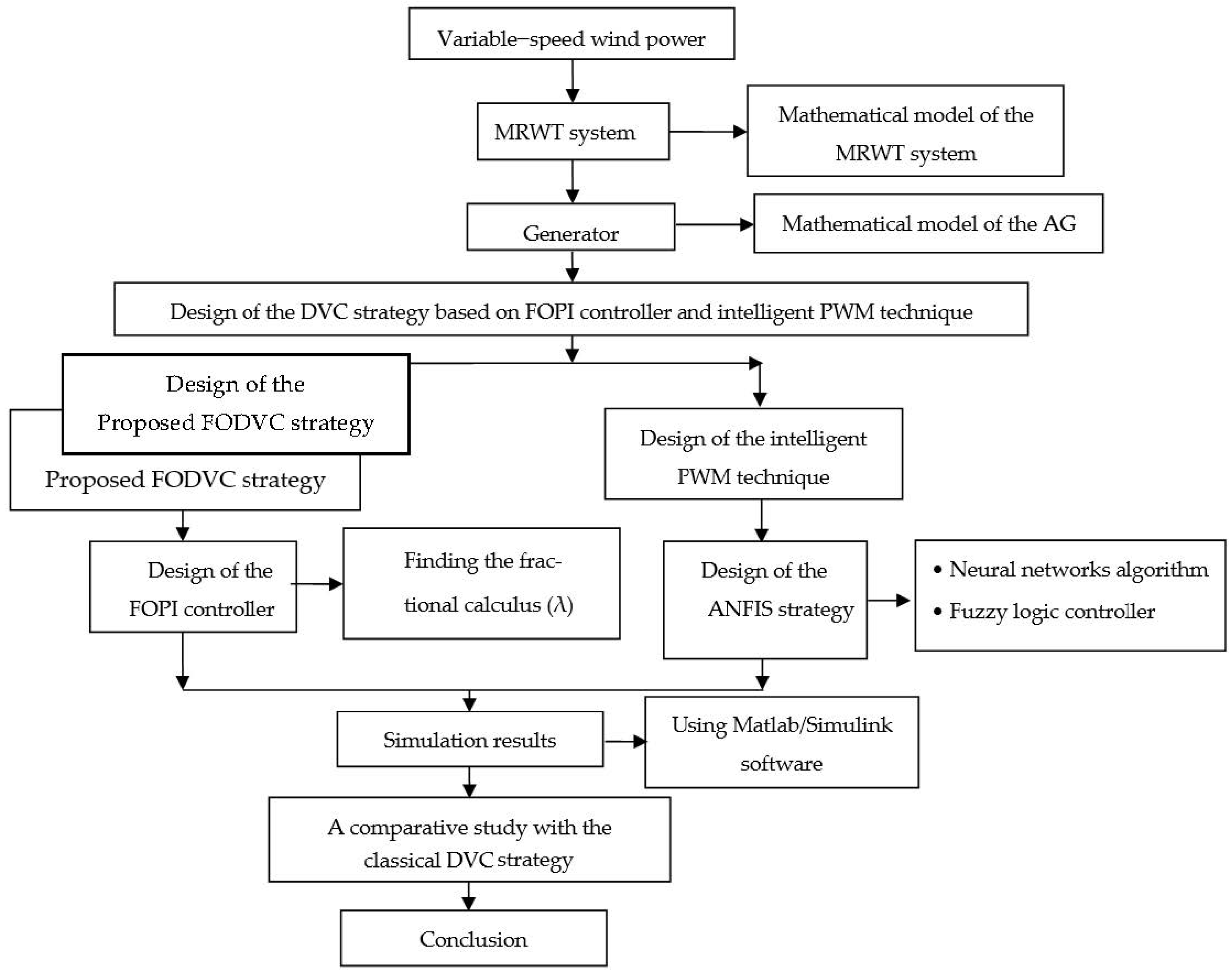
In order to understand the work performed in this paper, the design, testing, and validation stages of the proposed DVC strategy are shown in
Figure 1.
This work contains the following main themes: The
Section 1 gives an introduction to this work, mentioning its contributions and goals. In the
Section 2, the mathematical form of the proposed system consisting of a generator and an MRWT system for the generation of electrical energy is discussed alongside how this is performed. In the
Section 3 and
Section 4, the proposed IPWM technique and a new fractional-order PI controller are discussed, respectively. The classical DVC method is briefly discussed in the
Section 5. The
Section 6 is dealt with in minute detail concerning the proposed DVC-FOPI-IPWM technique used in the dual-rotor wind energy system. In the
Section 7, the simulated results of the proposed DVC-FOPI-IPWM method are given, where it is compared with the classical DVC method. Finally, all the conclusions reached from this work are collected in the
Section 8.
2. Multi-Rotor Wind Turbine System
Wind energy is one of the most important power sources used today for several reasons, including a low cost of production and an absence of toxic gases. In addition, to generate electricity from wind, we use wind farms. The latter contain wind turbines, which convert wind energy into mechanical energy. The acquired mechanical energy is used to rotate the generator, for example, as an asynchronous generator, thus producing electrical energy.
In conventional farms, a single-rotor turbine is used. This type of turbine has several problems. The energy gained from wind is not great by using this type of turbine [
41]. Moreover, this type of turbine is affected by the wind that is generated by wind farms [
42]. In order to overcome these difficulties and to increase the value of the mechanical energy gained from wind, it is necessary to develop a traditional turbine. Among the solutions proposed in the past few years is the adding of a second turbine to the main turbine, which doubles the value of the energy gained from the wind. In this way, new technology is created to generate electricity from wind with a multi-rotor turbine. This type has been studied in several scientific works [
43,
44,
45,
46].
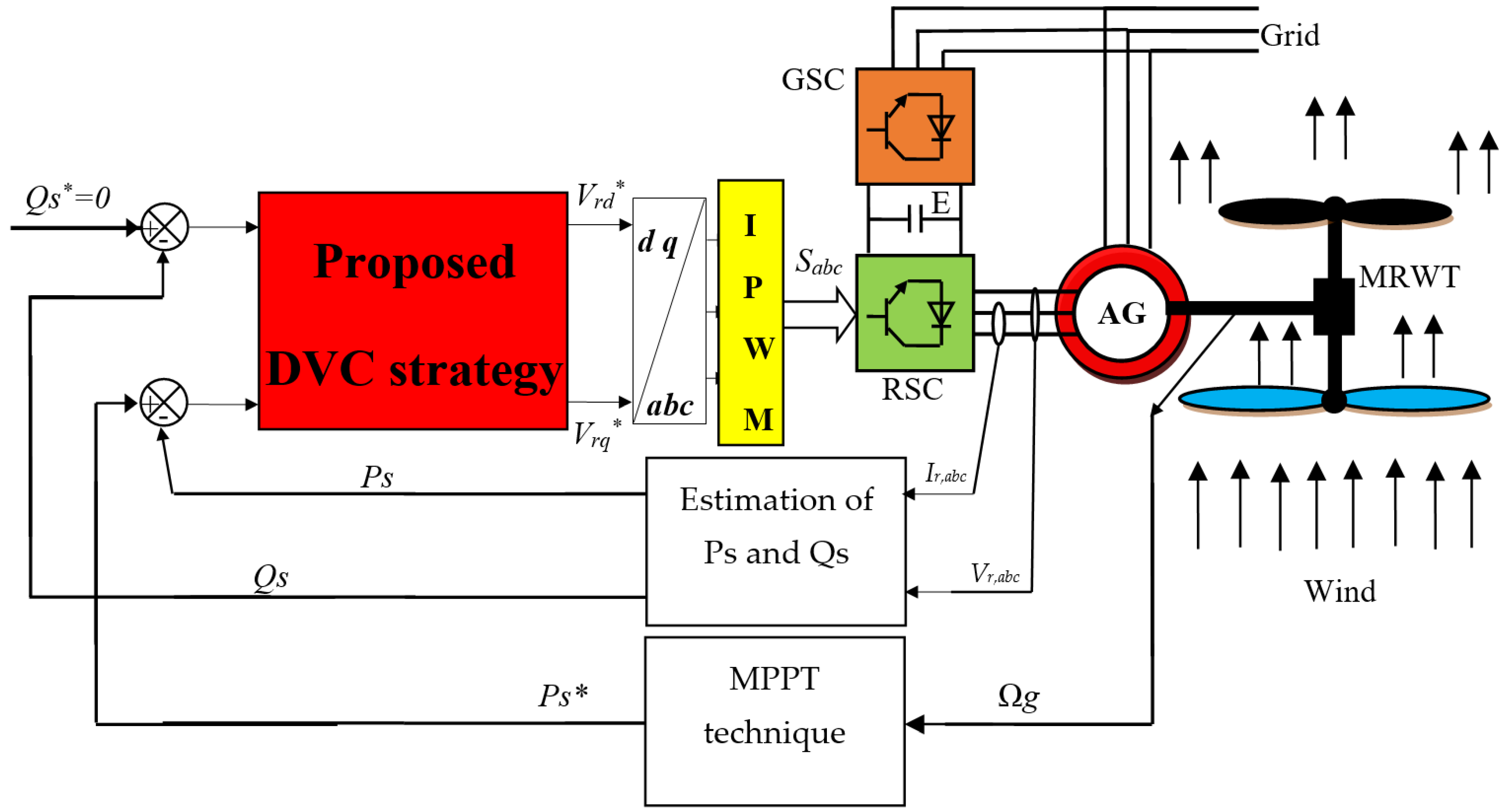
In this work, we study an MRWT system for the generation of electric energy from wind.
Figure 2 illustrates the electrical power generation system used in this work, where
Ps* and
Qs* represent the references for active and reactive power. In this way, this system is almost the same as the normal system used to generate electricity from wind, and the difference lies in the use of an MRWT system only. The use of an MRWT system leads to an increase in the mechanical energy gained from wind, thus obtaining a speed (torque) sufficient to rotate the asynchronous generator [
9].
In these new wind turbines, two rotors are used. The first is the main rotor, and the second is the auxiliary rotor [
8]. The use of rotors leads to the complexity of controlling this type. Additionally, this type of turbine is expensive and has a large number of mechanical parts compared to the old type. Moreover, this new technology requires more maintenance than the old technology [
10].
In an MRWT system, the output torque is the sum of the torques of the main and secondary turbines, and the same applies to the mechanical energy gained from wind. The total torque of the turbine can be expressed by relationship (1) [
13]:
where
Ta and
Tm are the torque of the auxiliary and main rotors [
14,
15]:
The energy gained from the dual-rotor wind turbine is the energy generated by the main wind turbine in addition to the mechanical power produced by the secondary wind turbine, and it is explained by relationship (3):
where
Pa and
Pm are the mechanical power of the auxiliary and main rotors, respectively.
Through Equation (3), the torque relationship can be clarified for each of the main and secondary wind turbines. It can be seen that the torque for the two wind turbines is related to both air density (ρ), mechanical speed (wa and wm), power coefficient (Cp), tip speed ratio (λa and λm), and the blade radius of the auxiliary and main rotors (Rm and Ra).
The relationship of the power coefficient almost remains the same as in the ordinary turbines (single-rotor). Equation (4) represents the relationship through which this coefficient can be calculated for a dual-rotor wind turbine.
Equation (4) shows that the pitch angle has a large effect on the power coefficient and therefore on the power gained, where the smaller that the pitch angle is, the greater that the coefficient is; therefore, the energy gained from the wind is large. Additionally, the coefficient’s power is affected by the value of the tip speed ratio. We find that the higher that the tip speed ratio is, the lower that the tip speed ratio value is; thus, the value of the energy gained from the dual-rotor wind turbine is lower and vice versa.
The tip speed ratios of the main and auxiliary wind turbines are given by Equation (5) for a dual-rotor wind turbine:
As is well known, determination depends on the wind speed of the auxiliary and main wind turbines (V1 and Vm), the blade radius of the auxiliary and main wind turbines, and the mechanical speed of the auxiliary and main wind turbines.
Wind speed (
) varies from the main turbine to the secondary. To calculate wind speed in the secondary turbine, we use relationship (6). This relationship is demonstrated in [
12].
Wind speed in the auxiliary wind turbine is related to the wind speed before the main turbine (
Vx), the distance from the auxiliary rotor disk (
x), and a thrust coefficient (
CT). In the turbine used in this work, the distance between the main and auxiliary turbines is 15 m, and the thrust coefficient is 0.9 [
10,
11,
12,
13,
14].
Among the components of the electricity generation system using dual-rotor wind turbines, we find the asynchronous generator and two inverters. Inverters are used to feed the rotor of the asynchronous generator [
6]. The first inverter aims to convert alternating current to continuous, whereas the second inverter converts direct current to alternating voltage.
To study this system, it is necessary to have the mathematical form of the AG-based MRWT system. As is well known, the generator has two parts; one is static, and the other is movable. The static part is called the stator and contains coils, and the rotating part is called the rotor, which is also composed of coils. The mathematical model of the AG uses the Park transform, in which both direct and quadrature flux and voltage are given. Equations (7) and (8) represent the direct and quadrature rotor voltage and flux of the AG, respectively [
7]:
Through these two equations, the direct and quadrature rotor voltage (Vdr and Vqr) is related to the direct and quadrature flux (φdr and φqr), the direct and quadrature rotor current (Idr and Iqr), and the resistance value (). Additionally, the flux is related to both direct and quadrature rotor current and to the rotor/mutual inductance of the rotor (M and Lr).
The direct and quadrature stator voltages (
Vds and
Vqs) of the generator are shown in Equation (9):
These voltages are concerned with quadrature and direct stator flux (
φds and
φqs), and this flux can be expressed by Equation (10) [
12]:
Equation (11) represents the mechanical equation of the AG-based MRWT system:
This equation shows the relationship between torque and mechanical rotor speed, and it explains how velocity changes in relation to torque. Through this equation, the change in mechanical rotor speed (Ω) is related to the load torque (Tr), electromagnetic torque (Te), viscous friction coefficient (f), and inertia (J).
Torque is given by Equation (12) [
3,
5]:
Equation (12) shows that change in torque is related to change in both direct/quadrature rotor current and direct/quadrature stator flux. Moreover, change in torque can be performed by changing the number of pole pairs (p).
Active and reactive power can be expressed by Equation (13):
Through Equation (13), it is possible to control the active and reactive power from direct and quadrature stator current and voltage. A change in stator voltages or stator current leads to a change in both the reactive power and the active power.
There are several ways to control the AG-based MRWT system, some of which are linear and some of which are nonlinear techniques. Among the most popular methods used in controlling electrical machines, there is DTC strategy, DPC technique, and vector control. In this work, the focus is on direct vector control, and this is because of its simplicity and ease of implementation. In this work, a new algorithm is given for this method, depending on both the proposed IPWM technique and the fractional-order PI controller. The proposed IPWM technique is explained in the third part of the article, and in the fourth chapter, a new fractional-order PI controller is addressed.
3. Proposed IPWM Technique
In electrical machines, the PWM technique is among the oldest and most widely used modulation methods for controlling electric motors due to its simplicity and ease of implementation [
47].
Figure 3 (on the left) represents the conventional PWM technique of the two-level inverter. In the PWM technique, two signals of different frequencies are compared, and a triangular signal with a frequency much greater than the frequency of the sinusoidal signal that represents the network’s voltage is used. Moreover, three hysteresis controllers are used to create the control signals (Sa, Sb, and Sc) of the inverter. The use of these conventional controllers causes variable frequencies at the output level of the inverter, where the inverter gives a sinusoidal signal of variable frequencies. Variable frequency is a major problem that affects the performance of electrical machines such as asynchronous generators. In addition, the use of a sinusoidal signal with variable frequencies leads to a decrease in the life of electrical machines [
48].
In order to overcome this problem and to obtain a sinusoidal signal with a fixed frequency, a method of artificial intelligence was used. In this proposed IPWM technique, classical hysteresis comparators are compensated by an intelligent method based on an adaptive neuro-fuzzy inference system (ANFIS) algorithm. Using this method leads to obtaining a high-quality sinusoidal signal (fixed frequency), thus overcoming the disadvantages of the traditional PWM method.
Figure 3 (on the right) represents the proposed IPWM technique in this work for controlling the inverter of the asynchronous generator. Through this figure, the proposed IPWM method is reverted to the classical PWM method with the substitution of the hysteresis controller by the ANFIS algorithm. In addition, the proposed IPWM method is simple and uncomplicated, does not require a specialist, and can be easily accomplished.
The ANFIS algorithm is one of the most important algorithms of artificial intelligence spread in recent times. In this type of algorithm, the advantages of neural networks are combined with the advantages of fuzzy logic. In this algorithm, rules are compensated by neural networks [
49].
Figure 4 represents the internal structure of the ANFIS algorithm.
Among the advantages of this algorithm are that it is simple, unrelated to the system, and can be applicated and implemented easily [
50]. However, among its downsides, there is no mathematical theory that explains how each of the rules selects the number of neurons within the middle layer of the neural network. Therefore, this algorithm depends on the experience of the user and on the extent of its application to automated systems. On the other hand, the ANFIS controller is very understandable and easy. It can also be applied to any system, regardless of its complexity, as it is not related to the studied system. The ANFIS controller is able to provide the most effective solution to complex issues. The system can be easily modified to improve or modify performance. Moreover, the ANFIS controller helps deal with engineering uncertainties.
The rules shown in
Figure 4 were used to implement the ANFIS algorithm. Regarding the membership functions (MFs) used to implement the ANFIS algorithm, they are shown in
Figure 5, where the same functions are used in the two inputs (error and change in error). In order to give more accuracy and to obtain excellent results, 49 rules were used. In addition, these rules were chosen based on experience, expert knowledge, and the dynamics of the process, whereby the greater that the number of these rules is, the slower that the system is.
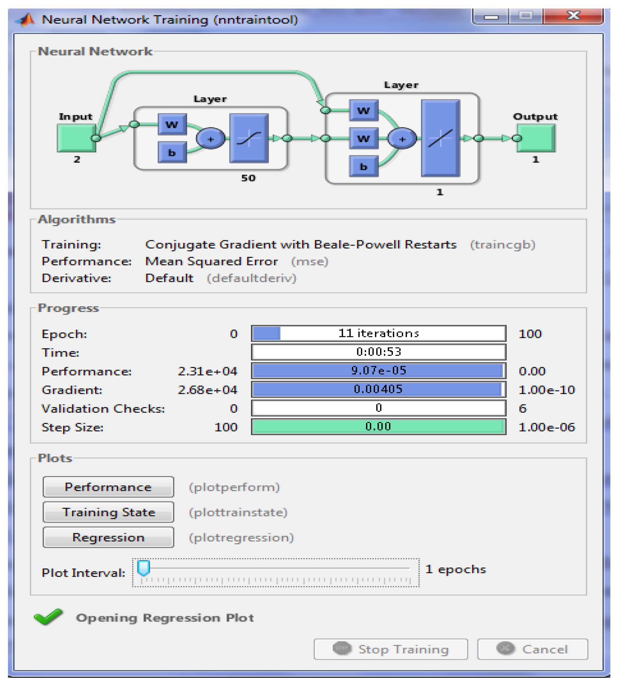
Regarding the neural networks, eight cells were selected in the inner layer, and in the outer and front layer, one cell and two cells were selected, respectively. The characteristics of the neural network used to perform ANFIS algorithms are shown in
Table 1. In order to implement the neural networks, a conjugate gradient with Beale–Powell restarts was used. The following functions were also used to obtain the neural networks: tansig, purelin, and traincgb.
The ANFIS algorithm training of the hysteresis comparators is shown in
Figure 6.
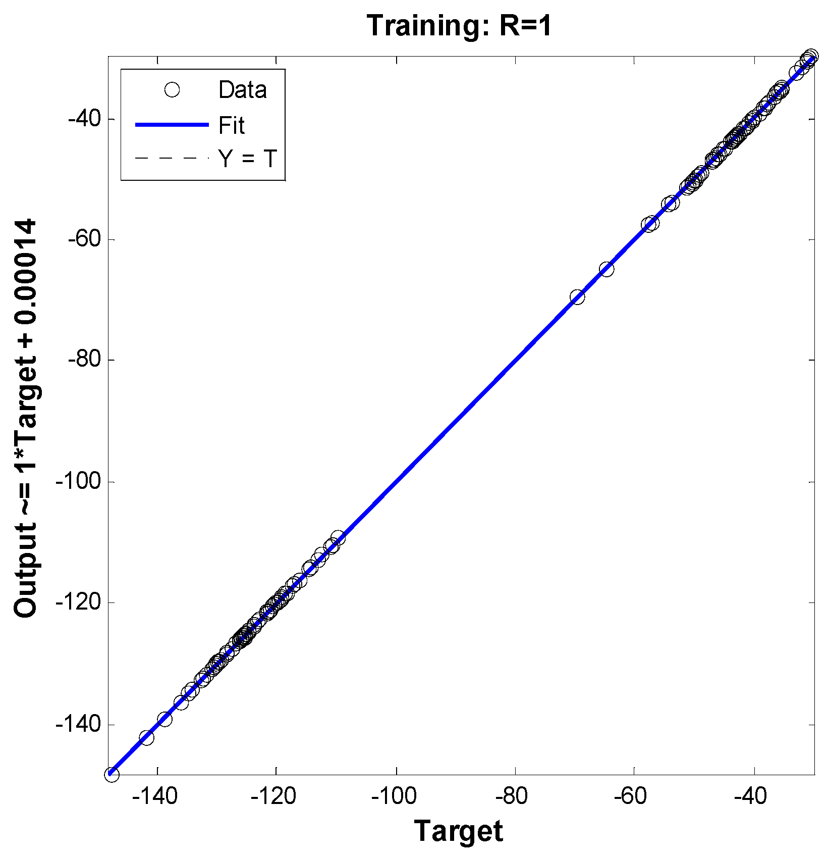
Figure 7 shows the training plot of the ANFIS algorithm for the hysteresis comparators. In this figure, the best training performance is 9.0749 × 10
−5 at epoch 10 for traditional hysteresis comparators. The error plot of the ANFIS algorithm is shown in
Figure 8, where the targeting field is [–140 –40], the training value is R = 1, and the output for hysteresis comparators is given by output = 1 × Target + 0.00014. Additionally, gradient, mu, and validation checks are shown in
Figure 9, and they represent the characteristics of the ANFIS algorithm of the traditional hysteresis comparators. In this figure, the best gradient, step size, and validation checks are 0.0040475, 0, and 0 at epoch 11, respectively.
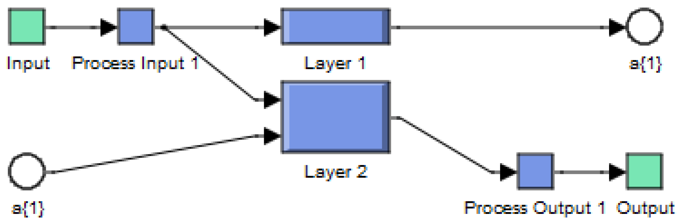
The internal structure of the neural network of the ANFIS controller is shown in
Figure 10. In this figure, the inner form of a neural network consists of two main parts: Layer 1 and Layer 2.
4. Proposed Fractional-Order PI Controller
In the fields of control theory and dynamical systems, a fractional-order system is a dynamical system that can be modeled by a fractional differential equation containing derivatives of non-integer order. Such systems are said to have fractional dynamics. However, fractional-order calculus (FOC) is one of the most popular and emerging mathematics branches that deals with differentiation and integration of real or complex order [
51]. Moreover, the FOC technique provides efficient tools for many situations related to chaotic behavior, infinite memory, and fractal dimensions [
52]. Additionally, fractional calculus is a mathematical method for improving the performance of classical methods, and it was used to improve the performance and effectiveness of the traditional PI controller. The use of this method gives great effectiveness in automated systems, especially in electrical power generation systems [
53,
54,
55,
56].
A combination of fractional calculus and the PI controller results in the creation of the FOPI controller, which is more robust compared to the classical PI controller. Using the FOPI method in wind power generation systems leads to a significant improvement in the quality of the current and the active power. Equation (14) shows the mathematical form of the FOPI controller, which is frequently used in wind power generation systems [
51]:
where
Ki is the integrating constant,
e(
t) is the error,
Kp is the proportional constant, and
λ is the fractional order of the integrating action.
The difference between the FOPI controller and the traditional PI controller lies in the use of fractional calculus (). By changing the value of the fractional order, the automated systems are well controlled, i.e., a good way to smooth the results is possible. In the case of λ = 1, the FOPI controller is the traditional PI controller.
In this work, we present a new form of fractional-order PI controller in order to improve the performance and efficiency of the DVC strategy of the asynchronous generator-based multi-rotor wind turbine system. In this part, a new form of the FOPI controller is given in order to reduce torque and active power ripples. In addition, the quality of the current is improved by decreasing the value of the THD. The proposed FOPI controller is different from the proposed FOPI controller in [
51,
53,
54,
55,
56].
The proposed mathematical form for the FOPI controller is shown in Equation (15):
where the fractional calculus of the FOPI controller is changed to calculus that is both integral and proportional. This suggested method is simple and easy. Additionally, the proposed FOPI controller can be applied to any linear or non-linear system.
Figure 11 shows the proposed FOPI controller in this paper. Based on this figure, the proposed FOPI controller is a simple structure and can be easily accomplished. Furthermore, the response of the proposed FOPI controller can be smoothed out by changing only one element (λ). Moreover, this proposed FOPI controller is not complicated.
This designed FOPI technique is used in this paper in order to improve the quality of both the current and the active power of an asynchronous generator controlled by direct vector control. In the next section of the paper, the necessary information and explanation of the DVC strategy are given.
5. Direct Vector Control
Traditionally, the DVC strategy is among the easiest and most widely used control methods that are available, and it depends on the use of a traditional PI controller, as we use this method in our PI controller. The use of the latter leads to a fast dynamic response and to a reduction in ripples at the level of both current and torque compared to hysteresis comparators. However, simplicity is one of the most important features of this strategy. The working principle of the classical DVC strategy is explained in [
57]. In this paper, this method is used to control a large power 1.5 MW AG-based MRWT system. Equations (16)–(19) illustrate the working principle of this method, which is based on the stator flux given by Equation (16):
In an asynchronous generator, the stator flux is related to stator voltage. The expressions for both direct and quadrature voltages are shown in Equation (17):
Based on Equations (16) and (17), the direct and quadrature currents are represented in Equation (18):
Regarding reactive and active power, they are related to both rotor current and stator flux, as we find that active power is related to both quadrature rotor current and stator flux. On the other hand, reactive power can be changed by changing both the direct current and the flux. Equation (19) shows both the active and reactive power of the AG [
19]:
The torque represented in Equation (12) becomes as follows:
Direct and quadrature rotor voltages can be expressed by Equation (21). A PI controller is used to give reference values for both direct and quadrature rotor voltages [
19]:
where
and
are the reference direct and quadrature rotor voltages.
In order to give a more illustrative picture of the working principle of the traditional DVC method and to facilitate the understanding of this method, the following figure (
Figure 12) shows the working principle of the traditional DVC method.
This figure was drawn based on Equation (21). The traditional DVC technique is very simple compared to the DTC strategy or to direct power control.
Despite its ease of implementation and simplicity, this traditional DVC technique gives unsatisfactory results or fewer results compared to both the DTC strategy and to the indirect FOC technique. Through the results shown in [
19], the classical DVC method gives more fluctuations at the level of current, torque, flux, and reactive power. Moreover, in this method, the THD value of electric current is higher compared to that of the DTC technique, the indirect FOC strategy, and direct power control, and this is because of using both a PI controller and the traditional PWM technique. As it is known, the use of the traditional PWM technique results in an electrical signal with a variable frequency, thus obtaining an unstable speed, and this is a big consequence of using this traditional DVC method. To overcome these obstacles found in the classical DVC method, a new idea for this classical DVC method is proposed, which is shown in the next section.
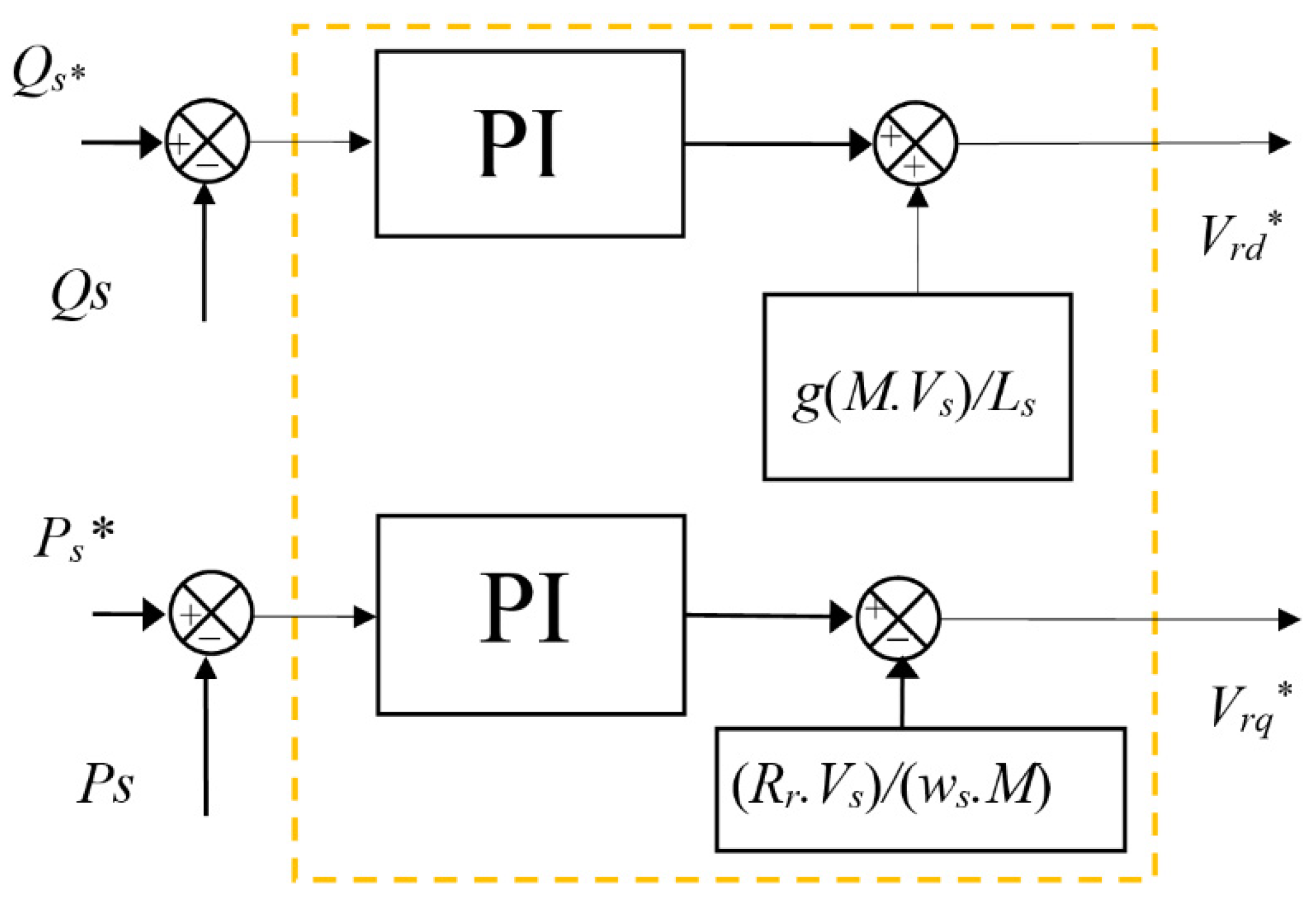
6. Proposed DVC Strategy
In order to ameliorate the performance and effectiveness of the classical DVC technique and to improve the quality of the electric current produced by the asynchronous generator placed in the multi-rotor wind electric power generation system, a new algorithm is given to the classical DVC method, using both the proposed FOPI controller and the proposed IPWM technique, which are used to keep the simplicity and ease of implementing the classical DVC technique. Moreover, the designed DVC technique is a change in the classical DVC method, in which the same shape is maintained with a change in both the traditional PI controller and the PWM technique by replacing them with the proposed FOPI controller and the proposed IPWM technique, respectively. All of this is performed to obtain satisfactory results in a simpler and more durable method. The proposed DVC method based on the FOPI controller using the IPWM technique of the AG integrated into an MRWT system is shown in
Figure 13.
In this proposed DVC method, the same level of estimation of both reactive and active power is used in the traditional method. Moreover, the reference value of the reactive power is set to zero, the reference value of the active power is related to the wind speed, and the maximum power point tracking (MPPT) technique is used to obtain the reference value of the active power.
In order to estimate both the reactive power and the active power, we need the stator flux. The latter is related to both current and voltage.
Equations (22) and (23) show how to obtain the stator flux.
The reference value for both direct and quadrature rotor voltages using the proposed DVC method is represented by Equation (24):
where λ is the fractional order (λ ≠ 0), which can take both positive and negative values.
The reference values of both the direct and quadrature rotor voltages are related to the reactive and active power references, respectively.
The errors of the reactive and active power are given by Equation (25):
If the value of λ is 1, the proposed DVC method becomes the classical DVC method. This is a positive aspect concerning the proposed method, as it is possible to cross from one method to another, and this is performed by changing the value of λ only.
Figure 14 represents the proposed DVC method for improving the performance and effectiveness of the classical DVC method.
In
Table 2, a comparison is given between the proposed DVC-FOPI using the ANFIS-PWM technique and the traditional DVC strategy. Through this table, the proposed DVC-FOPI using the ANFIS-PWM technique is more robust and reduces power ripples compared to the traditional DVC strategy. In the next section, the results are confirmed, and the robustness of the proposed DVC-FOPI with the ANFIS-PWM technique is verified using the Matlab/Simulink software.
7. Numerical Results
In this part, the designed technique is verified using a simulation in the Matlab program. In this work, the proposed fractional-order DVC (FODVC) strategy based on the ANFIS-PWM strategy (FODVC-ANFIS-PWM) is compared with the classical DVC strategy in terms of THD, ripples of torque, reactive power, current, and active power. A generator with a large amount of power is used to verify the proposed FODVC-ANFIS-PWM method. The generator’s parameters are taken from [
7,
19]:
Rs = 0.012 Ω,
Psn = 1.5 MW, 380/696 V,
Lr = 0.0136 H,
Lm = 0.0135 H,
J = 1000 kg·m
2,
Rr = 0.021 Ω, 50 Hz,
Ls = 0.0137 H,
p = 2, and
fr = 0.0024 Nm/s.
The robustness of the proposed FODVC-ANFIS-PWM method of the asynchronous generator integrated into an MRWT system is verified by using two tests, and this is always in comparison with the classical DVC method. The first test is used to study the behavior of the follower of the references, and the second test is used to study the change in the behavior of the proposed FODVC-ANFIS-PWM method in the event of a change in the generator’s parameters.
The results of this test are shown in
Figure 15.
Figure 15 represents current, reactive power, torque, and active power. In this figure, we find that the designed FODVC-ANFIS-PWM technique gives good results in terms of dynamic response. In addition, reactive and active power follow the references well, and this is for both the proposed and the traditional DVC method (see
Figure 15a,b). The active power changes according to the change in wind speed, by which we find that the greater that the wind speed is, the greater that the value of the active power is, and vice versa. The proposed FODVC-ANFIS-PWM technique gives satisfactory results in terms of its dynamic response to active power compared to the classical DVC strategy. Regarding the reactive power, it is zero, with the presence of ripples. Through these results, the proposed FODVC-ANFIS-PWM technique has a much better dynamic response to reactive power than the traditional DVC technique.
Figure 15c represents the torque of both strategies, and it takes the form of active power, as its value is affected by wind speed. Moreover, torque is related to active power, and its value increases as the value of the active power increases, as we find the value of the torque ranging between 0 Nm and −9000 Nm. Concerning the current, it is shown in
Figure 15d, where it is a sinusoidal current and where it is also related to wind speed. The change in current is related to the change in wind speed. Moreover, the current takes the form of active power, and its value increases as the value of the active power increases. We find that the largest value of the current is about 3000 A, and the lowest value is about 3000 A.
Figure 15e,f show the THD value of the stator current of both techniques. In
Figure 15e,f, it can be observed that the THD value is reduced for the proposed FODVC-ANFIS-PWM technique (0.10%) in comparison to the DVC technique (1.18%). The proposed FODVC-ANFIS-PWM technique minimizes the THD value of stator current by about 91.52%.
Figure 16 represents the ripples of the reactive power, torque, active power, and stator current of the traditional and proposed FODVC-ANFIS-PWM strategies. In this figure, the proposed FODVC-ANFIS-PWM strategy minimizes the ripples in the torque, reactive power, stator current, and reactive power in comparison to the classical DVC strategy.
In this test, the values of Rs, Ls, M, Lr, and Rr are changed to new values in order to study the behavior of the proposed method compared with the classical method. Moreover, this is performed in order to know the extent to which the proposed method is affected compared to the classical DVC technique in case the parameters of the studied system change. In this test, the values of Ls, Lr, Rs, Lm, and Rr become 0.00685 H, 0.0068 H, 0.024 Ω, 0.00675 H, and 0.042 Ω, respectively. The results obtained are illustrated in
Figure 17a–f.
Figure 17 represents the current, reactive power, torque, and active power of the proposed and traditional techniques. In these figures, the reactive power and the active power follow the references well, with a preference for the proposed FODVC-ANFIS-PWM method in the aspect of the speed of response time (see
Figure 17a,b).
The current and torque are represented in
Figure 17c,d, and each of them takes the same form as the active power, for which the greater that the value of the active power is, the greater that the values of both current and torque are. The maximum torque is 100 Nm, and the minimum value is −10,000 Nm for both DVC methods. The proposed FODVC-ANFIS-PWM method in this test gives an excellent value of THD (0.45%) compared to the DVC method (12.47%), and the reduction ratio is about 96.45%. Despite a change in some parameters of the generator, the proposed FODVC-ANFIS-PWM technique gives excellent results in terms of the value of the ripples’ amplitude of torque, current, reactive power, and active power compared to those of the traditional DVC method (See
Figure 18a–f).
The results obtained from the two tests are shown in
Table 3. In this table, the designed FODVC-ANFIS-PWM technique gives excellent results in terms of reducing the ripples of reactive power, torque, active power, and current, and this indicates the robustness of the designed strategy. Moreover, the proposed FODVC-ANFIS-PWM technique minimizes the active power ripple’s amplitude compared to the DVC method by about 99.99% and 99.96% in the first and second tests, respectively. Regarding the reactive power, the percentages are 99.93% and 99.97% in the first and second tests, respectively.
In the case of electromagnetic torque, the reduction rates are 93.33% and 97.50% in the first and second tests, respectively. The same applies to the stator current. The proposed FODVC-ANFIS-PWM method provides excellent ratios in the case of the two tests compared to the DVC strategy.
The proposed FOPI controller allows for smoother control of active and reactive power, and it minimizes the ripples of the torque, active power, and current of the AG-based MRWT system. The results show a significant reduction in electric current ripples and an improvement in the quality of the energy produced. It has already been shown that the FOPI controller is superior to the PI controller during sudden changes in wind speed, and this is in the case of either changing or not changing the parameters of the generator. In this paper, the RSC control method is implemented separately using the PI and proposed FOPI controller to compare their performances in the case of variable wind speed. The simulation results are shown in
Figure 15 and
Figure 17 and in
Table 3. The results show that, using a proposed FOPI controller, the amplitude of the ripples of torque, current, and active power is reduced. Therefore, the proposed FOPI controller has better performance and is more efficient in DFIG power control compared to other consoles. This indicates the robustness of the designed FODVC-ANFIS-PWM strategy in improving the quality of active power and electric current.
In
Table 4, the THD ratio of the electric current of the asynchronous generator obtained by the proposed FODVC-ANFIS-PWM method is compared with that obtained in some papers published in the most prestigious scientific journals. In this table, the designed FODVC-ANFIS-PWM technique provides a better THD value than several techniques, such as DTC, DPC, and indirect field-oriented control.


 ,
, 


