Article

Design of Fractional-Order Non-Singular Terminal Sliding Mode Observer Sensorless System for Surface-Mounted Permanent Magnet Synchronous Motor

1
Faculty of Transportation Engineering, Kunming University of Science and Technology, Kunming 650504, China
2
Wuxi Weifu High-Tech Co., Ltd., Wuxi 214028, China
*
Authors to whom correspondence should be addressed.
Electronics 2024, 13(8), 1601; https://doi.org/10.3390/electronics13081601
Submission received: 29 February 2024 / Revised: 31 March 2024 / Accepted: 17 April 2024 / Published: 22 April 2024
(This article belongs to the Special Issue Advances in Control for Permanent Magnet Synchronous Motor (PMSM))

Abstract

:
A new sensorless speed control system for a fractional-order terminal non-singular sliding mode surface-mounted permanent magnet synchronous motor is proposed. The fractional terminal non-singular sliding mode surface, which can converge in finite time, is designed by combining the fractional-order control theory with the terminal attractor concept. Then, a new control rate is proposed to reduce system buffeting. Secondly, an adaptive back electromotive force filter is designed to reduce the harmonics in the sliding mode function estimation and improve the observation accuracy. In addition, the theoretical analysis of the designed system proves that the system can converge in a finite time. Then, a fraction-order phase-locked loop with variable factors is designed to make the system more capable of tracking the rotor. Finally, a simulation and experiment platform is built, and a comparison experiment is carried out, which proves that the designed algorithm has a stronger rotor position tracking ability and a better dynamic performance of the system.

1. Introduction

The permanent magnet synchronous motor (PMSM) is widely used in aerospace, new energy development, the military, and other fields requiring high precision and wide speed due to its advantages of high power density, small size, low energy loss, and low rotor consumption [1,2,3]. The PMSM control system is a multi-variable and highly coupled nonlinear control system, which is easily affected by motor parameter changes and load disturbances, and it is difficult to ensure the motor speed stationarity and control accuracy [4]; therefore, excellent control algorithms have broad application prospects. In order to reduce the cost and extend the service life of the motor, the sensorless control algorithm has become the research focus of scholars at home and abroad in recent years. At present, sensorless control algorithms are mainly divided into the following two categories: the high-frequency injection method and the back electromotive force method. The high-frequency injection method can estimate the rotor position information by injecting a high-frequency carrier signal, which can make the motor system run stable in the low synchronous speed region [5] . However, the injected high-frequency signal will produce excessive electromagnetic torque and affect the dynamic performance of the system, and this method is only limited to the rotor position estimation of the salient pole structure [6]. The inverse electromotive force method uses the extended inverse electromotive force to estimate the rotor position. The inverse electromotive force method mainly includes the extended observer method, model reference adaptive method, and sliding mode observer method [7]. The literature [8,9] proposes the control strategy of an extended state observer. Although it can effectively improve the robustness of the system to inductance parameters, it increases the amount of mathematical calculation of the system design, increases the calculation load of the system, and reduces the stability of the system. The model reference adaptive method proposed in the literature [10,11] is simple in structure, but the system is easily affected by load and motor parameter changes.
The sliding mode observer (SMO) algorithm is a relatively effective sensorless observer method in the design of medium- and high-speed motor systems because of its simple structure, suitability for multiple precision system models, large range of motor parameters, and insensitive system transformation in the case of external interference [12,13,14]. The main working principle of the traditional sliding mode observer is to approximate the state error to the sliding mode surface by using the switching function. In the literature [15], the sigmoid function is used to the switching function as the control rate, which reduces the buffeting but decreases the robustness of the system. The total calculation amount of the system is small and the convergence speed is winged. However, due to the frequent switching signal, the inertia of the motor will increase the system chattering [16]. In order to improve the performance of the sliding mode observer and reduce the system buffeting, many optimization methods for the sliding mode observer have been proposed. The super-twisting sliding mode algorithm is used in reference [17], although this method can suppress buffeting and accurately estimate the speed and rotor position of the motor, it is sensitive to the disturbance of the system and has a poor robustness, so it is only suitable for first-order systems. The literature [18] proposes that although the second-order sliding mode based on the linear second-order sliding mode surface can effectively reduce chattering, it cannot guarantee that the sliding modulus will converge to zero in a finite time. In order to solve the problems of the above system. The literature [19,20] proposes a fast terminal sliding mode theory, which changes the possible problem of slow convergence of the sliding modes, and is also applicable to first-order systems. However, when the state variables of the system are reduced, the control input may tend to infinity in order to make the sliding mode operate normally, and a strange phenomenon may appear.
In order to reduce the ripple in the back electromotive force, the traditional sliding mode uses the low-pass filter to filter the back electromotive force, but this will cause position estimation delay. In addition, the traditional sliding mode uses the inverse tangent function to calculate the accurate rotor position, but the inverse tangent function will introduce chattering, resulting in the accumulation of errors. In the literature [21], an adaptive inverse electromotive force filter was designed to replace the low-pass filter, reduce the phase delay, and improve the estimation accuracy of the motor rotor position. The literature [22] uses a phase-locked loop instead of the arc-tangent function to estimate the rotor position. The rotor position tracking accuracy of PLL is high, and the system structure is simple, which will not cause the phase deviation of the rotor position estimation. However, the integral order integral factor used in PLL cannot fully match the performance requirements of the control system, so, PLL has some drawbacks. To solve this problem, fractional-order integral factors are introduced in this paper.
Fractional-order control is a rapidly developing research direction in the field of science and control, and occupies an important position in a variety of control systems [23,24]. The fractional-order control system can have a greater adjustment range in the integral order and differential order, which can improve the control performance of the system [25]. The literature [26,27] combines the fractional-order theory with the traditional PID controller to propose a fractional-order controller, which increases the adjustable parameters of the system and can better meet the control requirements of the system. The literature summary is shown in Table 1.
Based on the above analysis, in order to reduce the buffeting of the traditional sliding mode and obtain the accurate estimation of the rotor position of the surface-mounted permanent magnet synchronous motor (SPMSM), the dominating contributions made in this paper are as follows:
(1)
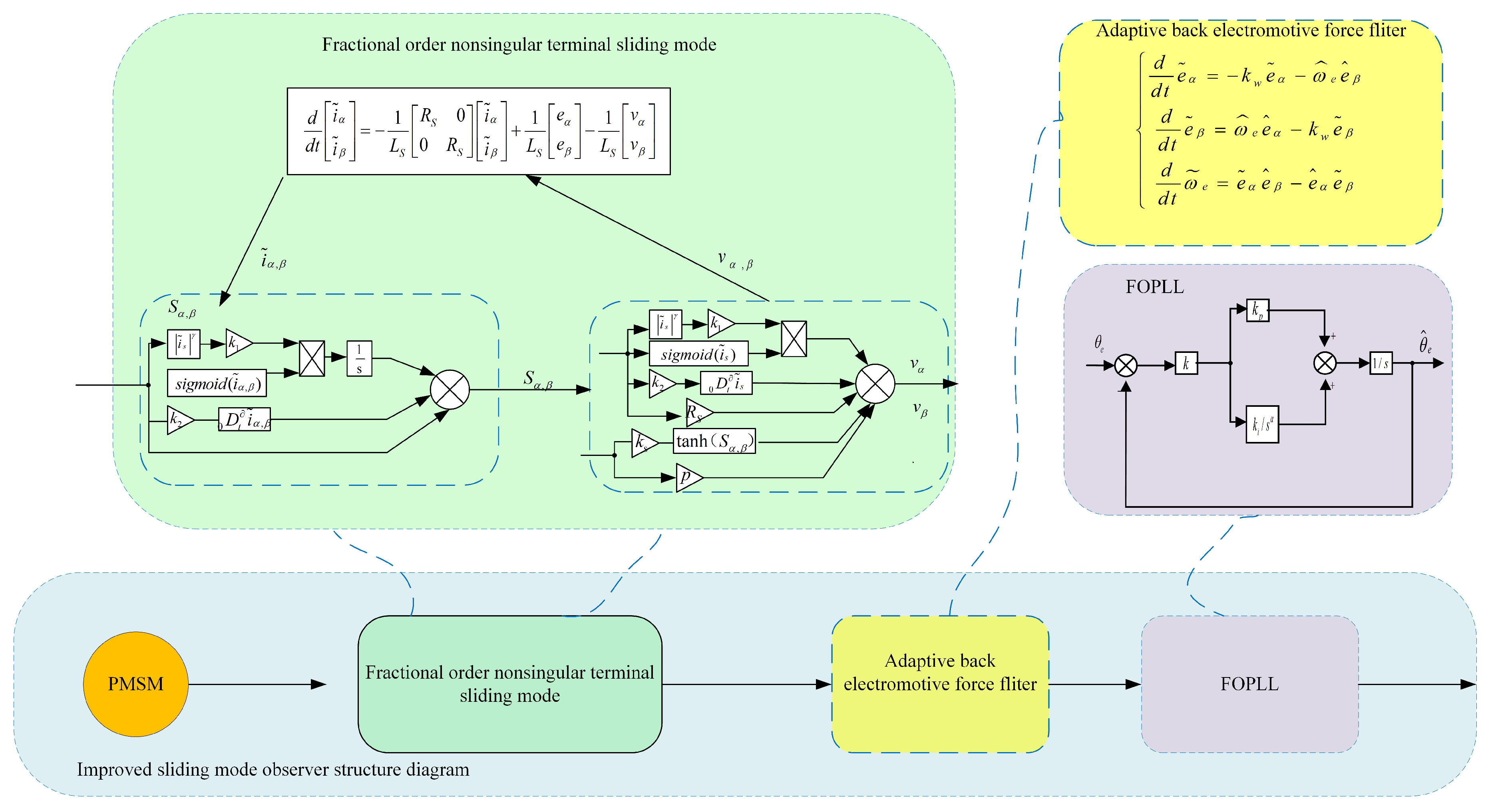
In this message, the fractional-order control is combined with the non-singular terminal sliding mode observer (NTSMO) to design fractional-order non-singular terminal sliding mode (FONTSMO). Furthermore, a new approach rate is designed to better fit the designed sliding mode surface to reduce the buffeting of the system, and it is proved by the mathematical analysis that the system can converge in finite time;
(2)
In order to eliminate the ripple in the back electromotive force and avoid the use of low-pass filters, this paper uses an improved adaptive back-EMF structure filter and performs the Lyapunov analysis on it;
(3)
Combining the fractional-order integral factor with the phase-locked loop, fractional-order phase-locked loop (FOPLL) is designed to replace the arc-tangent function.
Finally, simulation and experiment are carried out to verify the performance of the design system.

2. Mathematical Model of PMSM

2.1. Mathematical Model of Electric Machine

At present, most PMSM control is realized by constructing a mathematical model in the two-phase stationary coordinate system, and the mathematical equation of motor voltage is established as
u α u β = R + q L d ω e ( L d L q ) ω e ( L d L q ) R + q L d i α i β + e α e β
where R is the stator resistance, L d and L q is the stator inductance; q = d d t . e α e β T is the extended back electromotive force of the rest coordinate system α and β axis. i α i β T is the stator current because the motor selected in this paper is a SPMSM L d = L q = L s [28]. The estimate of the back electromotive force at this time is
e α e β = ω e ψ f sin θ e cos θ e
Equation (2), ω e is the electric angular velocity, ψ f is the rotor flux, and θ e is the electrical angle of PMSM, it can be seen that only the accurate estimation of the back electromotive force can accurately estimate the motor speed and rotor position. In order to facilitate the sliding mode observation of the extended back electromotive force, the voltage equation is rewritten into the current equation
d d t i α i β = 1 L S R S 0 0 R S i α i β + u α u β e α e β

2.2. Sliding Mode Observer

In order to calculate and estimate the operating state of the motor accurately, the mathematical equation of the second-order sliding mode observer is given as
d d t i ^ α i ^ β = D i ^ α i ^ β + 1 L S u α u β 1 L S v α v β
where, D = 1 L S R S 0 0 R S . R S is the resistance of the surface mounted motor and i ^ α and i ^ β are the observed stator current. v α and v β are the sliding mode control rate function. The mathematical expression of stator current error can be obtained by differentiating Equations (3) and (4) as follows:
d d t i ˜ α i ˜ β = R S L S 0 0 R S L S i ˜ α i ˜ β + 1 L S e α v α e β v β
i ˜ α i ˜ β = i ^ α i α i ^ β i β is represents the observed current error of the α axis and β axis; then define the sliding mode surface as
s α s β = i ˜ α i ˜ β
when the observer state variable reaches the sliding mode plane s α = 0 , s β = 0 , the observer state will remain on the sliding mode plane, the expression for the traditional sliding mode can be obtained as follows:
e α e β = v α v β = k c s i g n ( s α ) k c s i g n ( s β )
s i g n ( t ) = t / t t 0
where k c is the sliding mode gain of the traditional sliding mode. At this time, a discontinuous and high-frequency switching signal is calculated, so it is necessary to use a low-pass filter to filter the signal into a continuous signal. The low-pass filter is described as follows:
e ^ α e ^ β = 1 τ 0 e α e ^ α e β e ^ β = 1 τ 0 k c sign ( s α ) e ^ α k c sign ( s β ) e ^ β
where τ 0 is the time constant of the low-pass filter.
The sliding mode is further improved on the basis of Equation (7), the second-order sliding mode can be obtained as follows:
e α e β = v α v β = k α s i g n ( s α ) s α 1 / 2 + k β s i g n ( s α ) d t k α s i g n ( s β ) s β 1 / 2 + k β s i g n ( s β ) d t
where k α > 0 , k β is second-order sliding mode gains. Then, using the arctan function to calculate, the rotor angle can be obtained
θ ^ e = θ ^ e q + arctan ( ω ^ e / ω c ) θ ^ e q = arctan ( e ^ α / e ^ β )
where is the cut-off frequency of ω c low-pass filter, and the estimated rotational speed ω ^ e meets
ω ^ e = e ^ α 2 + e ^ β 2 ψ f
To sum up, the second-order sliding mode observer structure includes sliding mode observer, low-pass filter module and arctan function estimation rotor position module. Because of the second-order sliding mode observer system, the resonance is large in the estimation of rotor position, and the estimation accuracy is not high. Further improvement is needed.

3. Improve the Design of the Sliding Mode Observer

In order to solve the issue mentioned in Section 1, this paper first proposes a design of FONTSMO, then adds an adaptive feedback filter based on back electromotive force to replace the low-pass filter to filter the other electromotive forces, and finally designs the FOPLL to further reduce buffeting and meet the system control requirements.

3.1. Construction of Fractional-Order Terminal Non-Singular Sliding Mode Observer

By combining the fractional-order theory with the terminal non-singular sliding mode observer theory, the FONTSMO is constructed as follows:
S α S β = V α V β = i α ( τ ) i β ( τ ) + k 1 F ( α ) F ( β ) + D t 𝜕 0 i α ( τ ) i β ( τ ) k 2 F ( α ) F ( β ) = 0 t i ˜ α ( τ ) γ s i g m o i d ( i ˜ α ( τ ) ) d τ 0 t i ˜ β ( τ ) γ s i g m o i d ( i β ( τ ) ) d τ
where k 1 , k 2 are constants greater than 0, and 1 < γ , s i g m o i d ( t ) are power functions. The expression is as follows:
s i g m o i d ( t ) = 2 1 + e n t 1
n in the formula is a constant, and the value of sigmoid is further analyzed
s i g m o i d ( t ) ( 1 , 0 ] t 0 s i g m o i d ( t ) ( 0 , 1 ) t > 0
D t 𝜕 0 in Equation (13) is the factors are calculated in fractional-order. The fractional-order operator adopted in this paper is solved using the Riemann–Liouville definition [29], which is widely used in the field of fractional order calculus, and Oustaloup filter is used to select suitable frequency bands to further reduce harmonics. Among
  t 0 D t 𝜕 f ( X ) =   t 0 t f ( u ) d u 𝜕 , 𝜕 < 0 f ( t ) , 𝜕 = 0 d 𝜕 d t 𝜕 f ( t ) , 𝜕 > 0 .
The value range of 𝜕 selected in this formula is 2 < 𝜕 < 1 . When the observer’s state variable reaches the sliding mode plane with S α S β = 0 , the simplified Equation (13) is
i ˜ α i ˜ β = k 1   0 t i ˜ α γ s i g m o i d ( i ˜ α )   0 t i ˜ β γ s i g m o i d ( i ˜ β ) D t 𝜕 0 i ˜ α i ˜ β k 2
From Equation (17), it can be seen that D t 𝜕 0 i ( s ) k 2 and k 1   0 t i ˜ s γ s i g m o i d ( i ˜ s ) have the main guiding role in the movement of the system. Therefore, the system can converge at a faster rate, and there is no differential state when constructing the sliding mode surface, so there is no singularity.

3.2. Stability Analysis of FONTSMO System

In order to improve the performance of the observer and accurately estimate the motor speed and rotor position, the proposed control rate v s is composed of the equivalent control rate v e q and switch control rate v s w . The control rate is improved on the basis of the sigmoid function and combined with terminal sliding mode control, a new control rate is designed. The relationship is as follows:
v s = v e q + v s w v e q = L S ( k 1 i ˜ ( s ) γ s i g m o i d ( i ˜ ( s ) ) + k 2 ( D t 𝜕 + 1 0 i ˜ ( s ) ) ) R s i ˜ ( s ) v s w = k s tanh ( S ( s ) ) + p S ( s )
tanh ( t ) = e t e t e t + e t
where p > 0 is obtained by subtracting Equation (20) from Equation (3)
d d t i ˜ α i ˜ β = R S L S 0 0 R S L S i ˜ α i ˜ β 1 L S v α e α v β e β
According to modern control theory, in order to further judge the stability of the system, the Lyapunov equation is constructed as follows:
V = 1 2 S T S = 1 2 S α 2 + 1 2 S β 2
Take the derivative of Equation (20), there is
V = S T S = S α S α + S β S β = S α [ d i ˜ α d t + k 1 i ˜ α γ s i g m o i d ( i α ˜ ) + k 2 ( D t 𝜕 + 1 0 i ˜ α ) ] + S β [ d i ˜ β d t + k 1 i ˜ β γ s i g m o i d ( i ˜ β ) + k 2 ( D t 𝜕 + 1 0 i ˜ β ) ]
In Equation (22), define Z α , Z β as
Z α = S α [ d i α ˜ d t + k 1 i ˜ α γ s i g m o i d ( i ˜ α ) + k 2 ( D t 𝜕 + 1 0 i ˜ α ) ] Z β = S β [ d i ˜ β d t + k 1 i ˜ β γ s i g m o i d ( i ˜ β ) + k 2 ( D t 𝜕 + 1 0 i ˜ β ) ]
Equation (23) can be regarded as V = Z α + Z β , where Z α and Z β are mutually coupled, but the mathematical structure of the two terms is similar, so analyze one term
Z α = S α [ d i ˜ α d t + k 1 i ˜ α γ s i g m o i d ( i α ˜ ) + k 2 ( D t 𝜕 + 1 0 i α ˜ ) ] = S α ( 1 L S ( R S i ˜ α + e α v α ) + k 1 i ˜ α γ s i g m o i d ( i ˜ α ) + k 2 ( D t 𝜕 + 1 0 i ˜ α ) ) = S α ( 1 L S ( R S i ˜ α + e α ) ( k 1 i ˜ α γ s i g m o i d ( i ˜ α ) + k 2 ( D t 𝜕 + 1 0 i ˜ α ) R s i ˜ α ) + 1 L S k s tanh ( S α ) + 1 L S p S α + k 1 i ˜ α γ s i g m o i d ( i ˜ α ) + k 2 ( D t 𝜕 + 1 0 i ˜ α ) ) = S α L S ( k s tanh ( S α ) + p S α e α )
It can be seen from Equation (24) that when k s > e α , Z α < 0 exists when the state variable is on the sliding mode surface. There is a large range of observer convergence. The principle is similar to the above derivation process, and the derivation of Z β can be obtained
Z β = S β L S ( k s tanh ( S β ) + p S β e β )
It can see k s > e β when Z β < 0 . Therefore, when k s > e β k s > e α , k s R , the system is stable if Equation (26) is satisfied
V = Z α + Z β < 0
Let t r be the time from s ( 0 ) 0 to s ( 0 ) = 0 , and is s ( t r ) because of Z α = S α L S ( k s tanh ( S α ) + p S α e α ) S α L S ( k s tanh ( S α ) e α ) < 0 . It can be seen from the following formula that the system converges in finite time.
S α = 1 L S ( k s tanh ( S α ) e α ) s ( 0 ) s ( t r ) d s = 0 t r 1 L S ( k s tanh ( S α ) e α ) d t t r = S ( 0 ) ( ± k s L S + e α )
It is obtained when the sliding mode enters the boundary conditions
S α S β = 0
In this case, the Equation (20) is simplified
e α e β = v α v β = k α tanh ( S α ) + p S α k β tanh ( S β ) + p S β

3.3. Adaptive Back Electromotive Force Filter

In order to further reduce the system buffeting, avoid the use of low-pass filter, and improve the estimation accuracy of the system. In this paper, an adaptive back electromotive force filter is designed and its stability is analyzed observation.The filter structure is shown in Figure 1.
Using the derivative of Equations (2) and (30) is obtained as follows:
d e α d t = d ω e d t ψ f sin θ e + ω e 2 ψ f cos θ e d e β d t = d ω e d t ψ f sin θ e ω e 2 ψ f cos θ e
In a normal working environment, when d ω e d t = 0 is stable after the motor is started for a period of time, Equation (30) is simplified to Equation (31)
e s = d d t ω e ψ f sin θ e ω e ψ f cos θ e = ω e ω e ψ f cos θ e ω e ψ f sin θ e = ω e e β e α
The mathematical expression of the adaptive back electromotive force filter is further derived from Equation (31):
d d t e ˜ α e ˜ β ω ˜ e = k w e ˜ α ω ^ e e ^ β ω ^ e e ^ α k w e ˜ β e ˜ α e ^ β e ^ α e ˜ β
where: e ˜ ( s ) = e ^ ( s ) e ( s ) , ω ˜ e = ω ^ e ω e is the error value of the back electromotive force, e ^ α , e ^ β is the observed value of the extended back electromotive force, and k w > 0 is the filter gain. To verify the stability of the designed filter, the Lyapunov equation is constructed as follows:
V = 1 2 ( e ˜ α 2 + e ˜ β 2 + ω ˜ e 2 )
The differential analysis of Equation (33) is performed according to Equation (31)
V = e ˜ α e ˜ α + e ˜ β e ˜ β + ω ˜ e ω ˜ e = e ˜ α ( k w e ˜ α ω ^ e e ^ β ) + e ˜ β ( ω ^ e e ^ α k w e ˜ β ) + ( ω ^ e ω e ) ( e ˜ α e ^ β e ^ α e ˜ β ) = k w ( e ˜ α 2 + e ˜ β 2 ) 0
Equation (34) satisfies Lyapunov’s stability theorem, indicating that the adaptive inverse electromotive force filtering algorithm is stable.

3.4. Design of FOPLL Motor Rotor Position Estimation Module

Since the inverse tangent function will bring the buffering of the sliding mode observer into the rotor position calculation, the error accumulates. In order to solve this problem, this paper uses FOPLL to replace the inverse tangent function.
The fractional-order PI controller has appreciable robustness, and the fractional-order participation makes the system adjustable parameters increase, and the designed control system is more in line with the requirements of the required working conditions. In this paper, the fractional-order PI controller and phase-locked loop are combined to design FOPLL, as shown in Figure 2.
The FOPLL designed in Figure 2 consists of a phase discriminator, a loop filter, and a voltage controlled shaker For θ ^ e θ e < π 6 and k = ω e ψ f , sin ( θ ^ e θ e ) = θ ^ e θ e can be approximated. So Δ e can be computed using trigonometric function relations
Δ e = e ^ α cos θ ^ e e ^ β sin θ ^ e = k sin θ e cos θ ^ e k cos θ e sin θ ^ e = k sin ( θ e θ ^ e ) = Δ k ( θ e θ ^ e )
The FOPLL transfer function and the rotational speed error transfer function can be further described
G c ( s ) = θ ^ e ( s ) θ e ( s ) = k k P S r + k k i s 1 + r + k k P S r + k k i
G e ( s ) = Δ e ( s ) θ e ( s ) = s 1 + r s 1 + r + k k P S r + k k i
Here, because of the fractional-order 0 < α < 1 , the speed θ e ( s ) can be approximated as a ramp signal when the motor is running at a constant speed, and the steady-state error can be obtained by the following formula:
Δ e ( ) = lim s 0 s Δ e ( s ) = lim s 0 s α s 1 + r + k k p s α + k k i = 0
Equation (38) means that the FOPLL is designed to accurately track the PMSM rotor position. In order to study the system performance of FOPLL and further verify the performance of FOPLL, the building FOPLL bode diagram is shown in Figure 3.
It can be seen that with the increase in the fractional-order integral factor α , the cutoff frequency range of fractional-order PLL increases, but the relative phase delay increases. It can be seen that when α = 1 , the fractional-order PLL is a traditional integer order sliding mode. This means that the PLL with a better effect can be obtained by changing the fractional-order integral factor.
Based on the above factors, the improved partial structure diagram is shown in Figure 4 below. In this paper, a novel FONTSMO observer motor control system is designed by combining the novel approach rate, fractional terminal singular sliding mode, adaptive back electromotive force filter, and fractional phase locked loop.

4. Simulation Analysis and Experimental Verification

In order to verify the feasibility of the designed FONTSMO estimation method, a sensorless PMSM speed regulation system model was built on the MATLAB/Simulink 2022a simulation platform , and the simulation waveform of the traditional sliding mode observer, second-order sliding mode observer, and the designed FONTSMO was compared to analyze the dynamic characteristics of the system under the condition that the initial state parameters of the motor were consistent. Figure 5 is the FONTSMO system control diagram.
In order to simulate the real operating state of PMSM system and verify the proposed FONTSMO strategy, the initial variables of the system and the initial parameters of PMSM need to be set. The PMSM ontology parameters adopted in this paper are shown in Table 2.

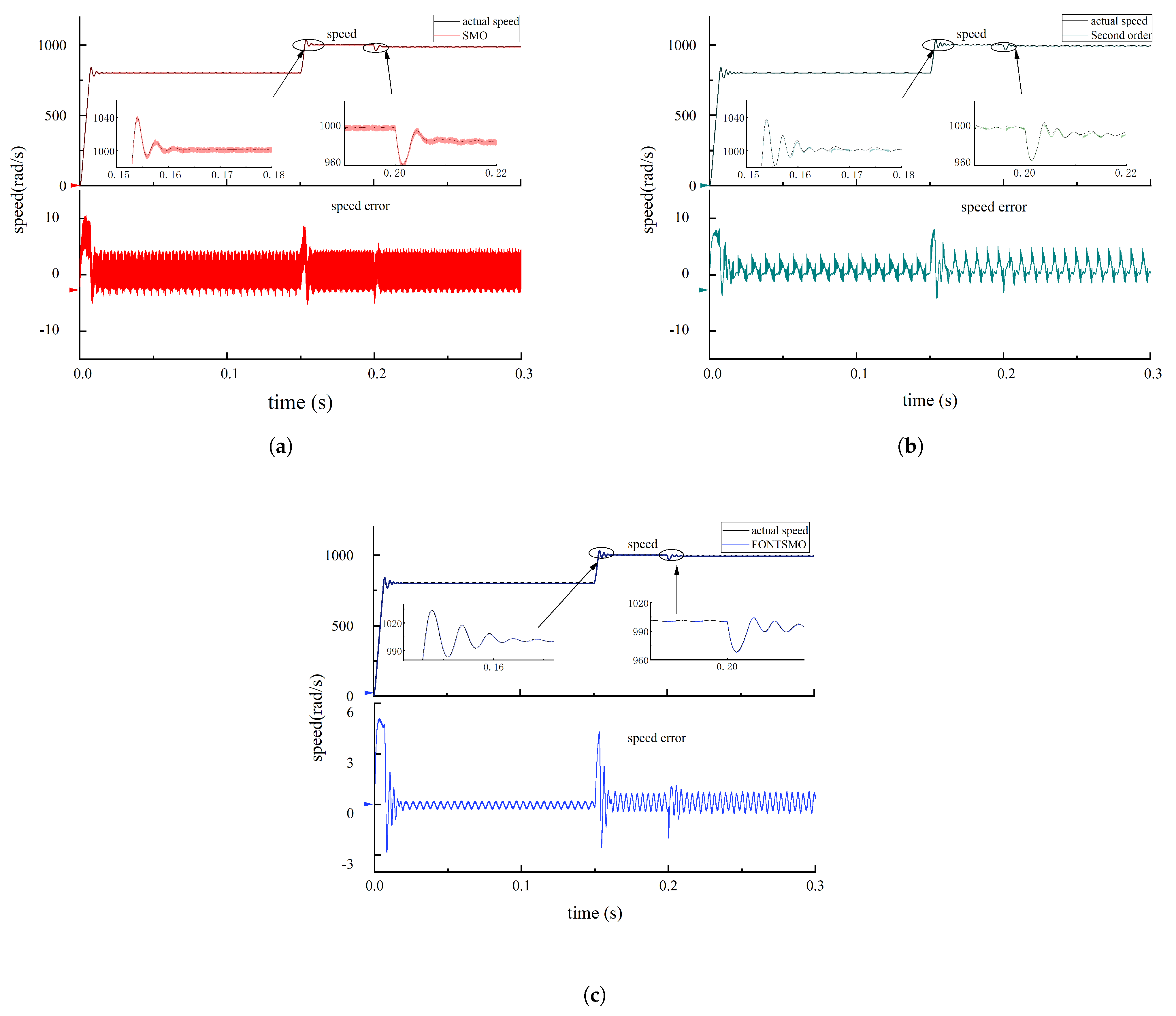
4.1. Simulation Analysis

FONTSMO is simulated to verify the control performance of the system. The simulation time is 0.3 s, the initial speed of the motor is 800 rad/s no-load, the motor speed is increased to 1000 rad/s at 0.15 s, and the motor is suddenly loaded with 8 N · M when the time is 0.2 s, the simulation results are observed and the simulation characteristics of the system are analyzed. Table 3 shows the results of the three sliding mode simulations.
The following Table 4 lists the parameters of the three solutions. Because the PI of the current loop and the speed of the three schemes did not improve, the PI control parameters of the current loop and the speed loop of the three schemes were the same. The PI in the table refers to the PI control of the speed loop.
Figure 6a–c show the three-phase current waveform and the Fourier analysis of the traditional sliding mode observer, second-order sliding mode observer, and the fractional non-singular terminal sliding mode observer under preset simulation conditions, respectively. It can be seen from Figure 6a that the total harmonic distortion of the three-phase current of the traditional sliding mode observer reaches 17.81%, in which the content of the fifth, seventh, and ninth harmonics is large, indicating that the traditional sliding mode observer is not ideal in suppressing the harmonic of the three-phase current, and it is difficult to achieve a good harmonic suppression effect. It can be acquired from Figure 6b that the total harmonic distortion rate of FONTSMO’s three-phase current is 7.86%. It can be acquired from Figure 6c that the total harmonic distortion rate of FONTSMO’s three-phase current is 5.36%, and the suppression effect of the fifth, seventh, and ninth harmonics is more obvious, and the suppression effect of the three-phase current is better.
Secondly, in order to verify the motor control effect of FONTSMO control algorithm in global simulation, the speed and speed error of the two control methods are further analyzed.
Figure 7a are speed graphs and speed error graphs of traditional sliding mode observers, respectively. It can be seen that in the three stages of initial start, acceleration, and loading, the motor controlled by the traditional sliding mode observer algorithm can quickly reach the predetermined speed, but the speed estimation error of the traditional sliding mode observer algorithm reaches 4.6 rad/s. The estimation error of rotational speed is large, and the estimation accuracy of the algorithm needs to be improved.
Figure 7b is the speed observation and error diagram of the second-order sliding mode. It can be seen that the speed error of the motor under the control of the second-order sliding mode observer algorithm is 4.1 rad/s. Compared with the traditional sliding mode observer algorithm, the buffeting of the second-order sliding mode observer algorithm is not reduced. Further improvement is still needed.
Figure 7c, respectively, show the speed diagram and speed estimation error diagram under the control of FONTSMO algorithm. Compared with the traditional sliding mode observer algorithm, the speed estimation error of the FONTSMO algorithm is 1.76 rad/s, the speed waveform is smoother, the speed estimation error is small, and the dynamic characteristics of the system can be effectively improved.
The traditional sliding mode observer and second—order sliding mode observer use a low-pass filter, so there is a certain phase delay in estimating the rotor position. The FONTSMO design avoids the use of low-pass filters and improves the motor estimation accuracy. Figure 8a shows the rotor position estimation diagram and rotor position estimation error diagram of the motor with traditional sliding mode, respectively. It can be seen that the maximum position estimation error of the traditional sliding mode is 0.05 rad.
Although the second-order sliding mode observer introduces an integral link in the control rate, it can be seen from Figure 8b that the estimation error of the algorithm in the rotor position is 0.042 rad, and there is a lot of resonance, which needs to be further improved.
Figure 8c is , respectively, the rotor position estimation diagram and the position estimation error diagram of FONTSMO. It can be seen that the position estimation error of FONTSMO observer is 0.018 rad. It can be seen from the analysis that compared with the traditional sliding mode observer algorithm, the FONTSMO algorithm can effectively reduce the estimation delay. Moreover, the estimation accuracy of the motor rotor is improved.

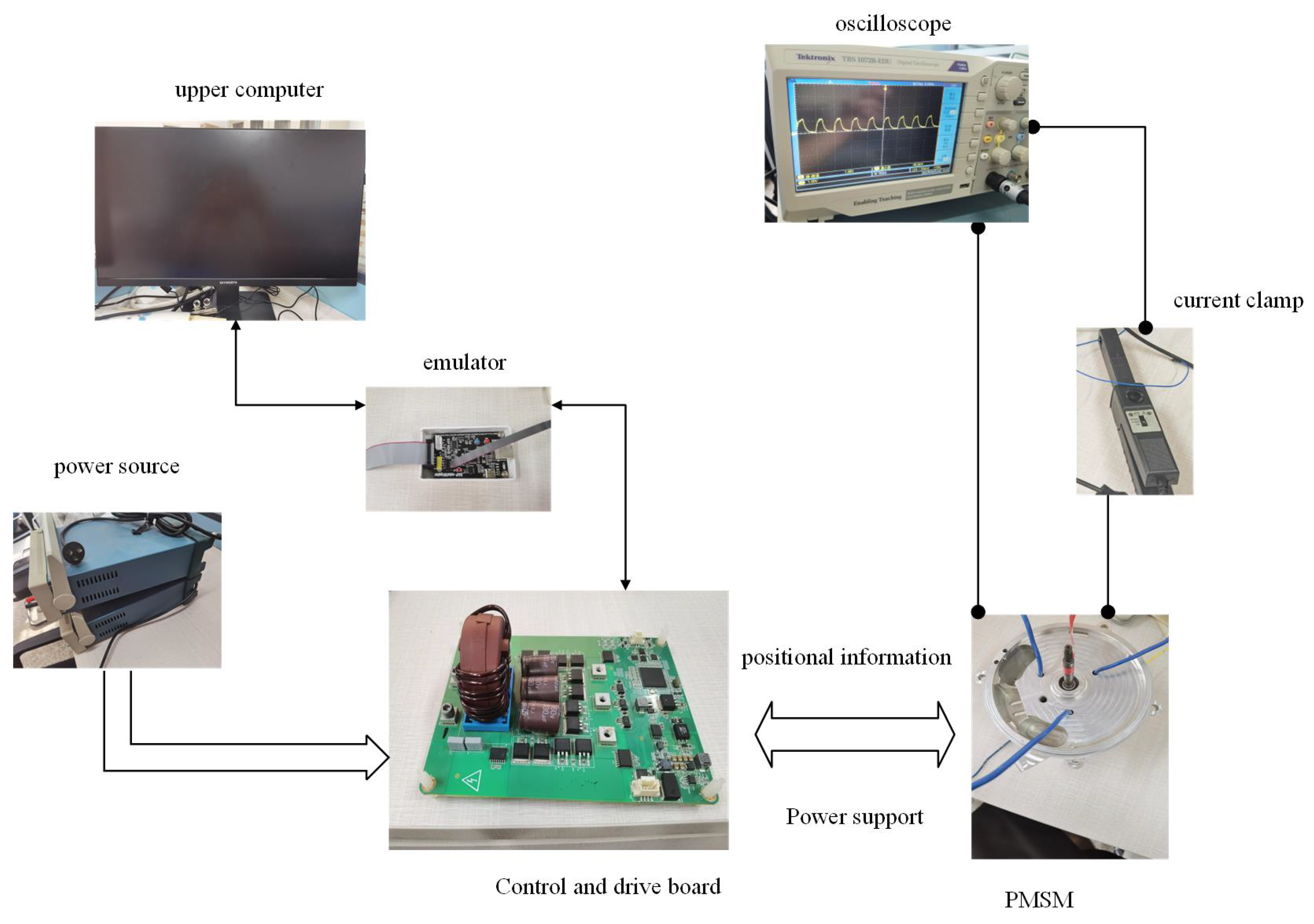
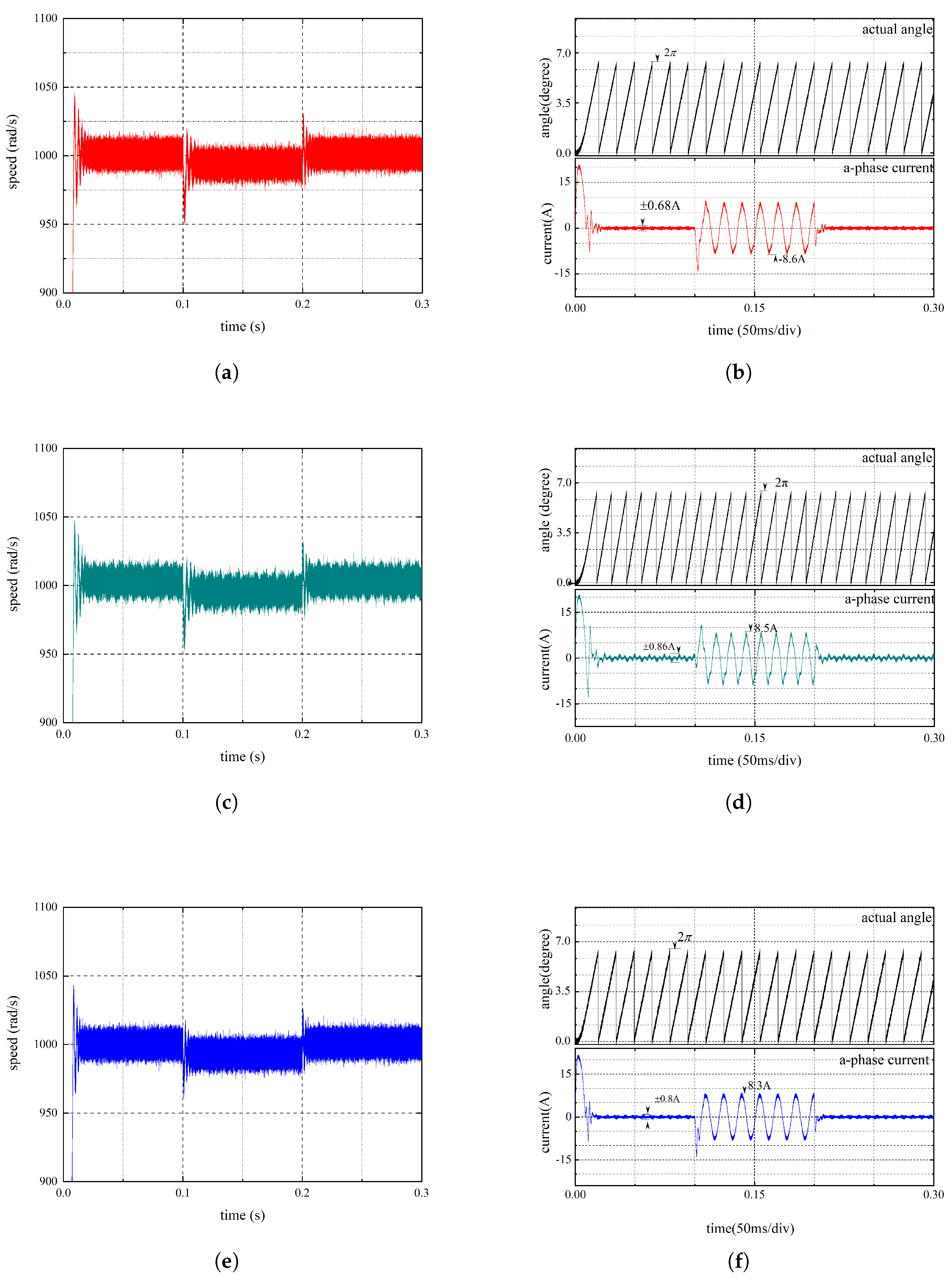
4.2. Experimental Verification

In order to verify the effectiveness of FONTSMO, the SPMSM experimental platform was built. The experimental parameters were consistent with those in Table 2 and the experimental scheme was shown in Figure 9. The experimental platform mainly includes the following three parts:
(1)
Operative part: SPMSM. The motor is connected to the control board, and the sensor on the motor can transmit the position information of the motor during operation back to the control and drive board for the upper computer to read;
(2)
Power supply: DC power supply. This part separately supplies power to the motor and the control board;
(3)
Main control part: upper computer, DAPminiWiggler, control, and drive-integrated control board equipped with an Infineon TC277 chip. The TC277 chip has a maximum clock of 200 MHz and a three-core architecture, which is suitable for a variety of system conditions. The experiment mainly used the C language to write motor control code on a Tasking platform. The main modules used are ADC (analog-to-digital Converter) and GTM (generic timer module). The ADC mainly samples the motor, and the GTM can generate controlled pulse width modulation (PWM) to drive the motor.
In order to study the performance of the FONTSMO system, only acceleration and deceleration experiments were performed on the motor. The whole experiment took 0.3 s, with the motor starting at an initial speed of 1000 rad/s, accelerating to 1200 rad/s at 0.1 s, and decelerating to 1000 rad/s at 0.2 s. Observe the motor speed, rotor position estimation, and rotor position estimation error to judge the design.
From Figure 10a–f, it is obtained that the variable speed stability time of FONTSMO is 0.008 s, and the maximum speed overshoot is 69 rad/s. The stability time of the second-order sliding mode is 0.01 s, and the maximum speed overshoot is 88 rad/s. The traditional sliding mode variable speed stability time is 0.01 s; the maximum speed overshoot is 81 rad/s.
In order to further study the two control strategies under the control of the motor under load, the dynamic characteristics of time were used. Accelerate the motor to 1000 rad/s, apply a load of 8 N · M to the motor when it runs to 0.1 s, and remove the load at 0.2 s. Furthermore, record the motor operating conditions within 0.3 s. Figure 11a–f are the speed diagram of the traditional sliding mode under sudden load, the rotor position estimation diagram, and the A-phase current diagram of the motor.
As can be seen from Figure 11a–d, it takes a long time for the motor controlled by the traditional sliding mode observer algorithm and the second-order sliding mode algorithm to reach stability after loading and unloading, and the traditional sliding mode stability time is 0.01 s. The maximum velocity overshoot is 52 rad/s, the second-order sliding mode stabilization time is 0.008 s, and the maximum velocity overshoot is 57 rad/s. Figure 11e,f shows the velocity diagram, the rotor position estimation diagram, and the A-phase current diagram of the motor controlled by the FONTSMO algorithm under sudden loading and unloading. The motor stabilization time controlled by the FONTSMO algorithm is 0.006 s, and the maximum overshoot is 37 rad/s. The experimental results show that the FONTSMO algorithm is better than the traditional sliding mode observer algorithm to control the dynamic performance of the motor.

4.3. Result and Discussion

Combined with Section 4.1 and Section 4.2, the most important evaluation parameters of the system in this paper are that the current SNR is 5 . 36 % , the maximum speed error is 1.76 rad/s, and the rotor position error is 0.018 rad. The FONTSMO variable speed stability time is 0.008 s, the maximum speed overshoot is 69 rad/s, the overshoot of the loading experiment is 37 rad/s, and the stabilization time is 0.006 s. The following Table 5 is a comparison with the other literature.
It can be seen from the simulation results that the current-to-noise ratio of FONTSMO is 5 . 36 % , while the current-to-noise ratio of the traditional sliding mode is 17 . 81 % , and the second-order sliding mode is 7 . 86 % . The results show that this method can effectively suppress current ripple. The maximum speed error and angle error of the FONTSMO system are 1.760 rad/s and 0.018 rad, while the speed error and angle error of the traditional sliding mode system are 4.6 rad/s and 0.05 rad. The velocity error of the second-order sliding mode system is 4.1 rad/s, and the angle error is 0.42 rad.
It can be seen from the variable speed experiment that the variable speed stability time of FONTSMO is 0.008 s, and the maximum speed overshoot is 69 rad/s. The stability time of the second-order sliding die is 0.01 s, and the maximum speed variable is 88 rad/s. The traditional sliding mode variable speed stability time is 0.01 s, and the maximum speed change is 81 rad/s In the loading experiment, it takes a long time for the motor controlled by the traditional sliding mode observer algorithm and the second-order sliding mode algorithm to reach stability after loading and unloading. The traditional sliding mode stability time is 0.01 s, and the maximum velocity change is 52 rad/s. The second-order sliding mode stability time is 0.008 s, and the maximum velocity change is 57 rad/s. The maximum velocity variation in the system is 37 rad/s, and the stability time of the system is 0.006 s.
It can be seen from the experiment that the maximum speed change in the traditional sliding mode and the second-order sliding mode after loading is 52 rad/s. The maximum speed change in FONTSMO is 37 rad/s, and the stable time of the FONTSMO system is 0.006 s, while the traditional sliding mode is 0.01 s and the second-order sliding mode is 0.008 s.
In summary, the FONTSMO system designed in this paper is more accurate than the other methods in estimating the rotor position of the motor, and the designed system has better dynamic performance.

5. Conclusions

In this paper, a speed sensorless surface mount permanent magnet synchronous motor control system based on the fractional-order and terminal non-singular sliding mode observer is designed. A new approach rate adapted to the designed sliding mode function is proposed. The influence of noise in the system is reduced by introducing an adaptive back electromotive force filter and fractional-order phase-locked loop. Finally, the designed system is analyzed mathematically, and it is proven that the system can converge in finite time. In this paper, the designed fractional-order PLL is compared with the traditional sliding mode observer and the second-order sliding mode observer. The experimental results show that this method improves the tracking accuracy of the motor position and reduces the buffeting of the system.

Author Contributions

Conceptualization, G.Y., J.L. and Y.X.; methodology, Y.X. and J.L.; software, J.G.; validation, G.Y., J.L, S.H. and Y.X; formal analysis, J.G.; investigation, J.G.; resources, J.G.; data curation, J.G.; writing—original draft preparation, J.G.; writing—review & editing, G.Y.; visualization, J.G.; supervision, G.Y. and Y.X.; project administration, G.Y.; funding acquisition, G.Y. All authors have read and agreed to the published version of the manuscript.

Funding

This research was funded by the Development of a Domestic Electronic Control System (ECU) for the China VI diesel engine under grant No. 202104BN050007, Key Technology Research and Development of a methanol/diesel dual fuel engine under grant No. 202103AA080002 and the Research and Application of Key Technologies for extended-range commercial electric vehicles under grant No. 202102AC080004.

Data Availability Statement

Data are available upon request from the authors.

Conflicts of Interest

Author Shaojun Han was employed by the company Wuxi Weifu High-Tech Co. The remaining authors declare that the research was conducted in the absence of any commercial or financial relationships that could be construed as a potential conflict of interest.

Abbreviations

The following abbreviations are used in this manuscript:
AbbreviationMeaning
SPMSMSurface-mounted permanent magnet synchronous motor
PMSMPermanent magnet synchronous motor
NTSMONon-singular terminal sliding mode observer
FONTSMOFractional-order non-singular terminal sliding mode
FOPLLFractional-order Phase-locked loop

References

  1. Zhou, Q.; Zhang, Y.; He, H.; Li, W.; Qi, X. Study on Location Detection of PMSM Rotor Based on Sliding Mode Observer. In Proceedings of the 2016 International Symposium on Computer, Consumer and Control (IS3C), Xi’an, China, 4–6 July 2016; pp. 77–80. [Google Scholar] [CrossRef]
  2. Matraji, I.; Al-Durra, A.; Errouissi, R. Design and experimental validation of enhanced adaptive second-order SMC for PMSG-based wind energy conversion system. Int. J. Electr. Power Energy Syst. 2018, 103, 21–30. [Google Scholar] [CrossRef]
  3. Chen, S.; Lin, F. Robust nonsingular terminal sliding-mode control for nonlinear magnetic bearing system. IEEE Trans Control Syst Technol. 2011, 19, 2050484. [Google Scholar] [CrossRef]
  4. Zhang, L.; Li, H.; Shan, L.; Zhang, L.; Zhang, L. Double-hierarchical fuzzy exponential convergence law fractional-order sliding mode control for PMSM drive control in EV. Eng. Sci. Technol. Int. J. 2023, 47, 101536. [Google Scholar] [CrossRef]
  5. Zhang, Y.; Yin, Z.; Du, C.; Liu, J.; Sun, X. Noise Spectrum Shaping of Random High-Frequency-Voltage Injection Based on Markov Chain for IPMSM Sensorless Control. IEEE J. Emerg. Sel. Top. Power Electron. 2020, 8, 3682–3699. [Google Scholar] [CrossRef]
  6. Bin, X.; Luo, X.; Zhu, L.; Zhao, J. Sensorless Control of Dual Three-Phase PMSM with High Frequency Voltage Signal Injection. In Proceedings of the 2019 22nd International Conference on Electrical Machines and Systems (ICEMS), Harbin, China, 11–14 August 2019; pp. 1–4. [Google Scholar] [CrossRef]
  7. Wang, G.; Zhang, H. A new speed adaptive estimation method based on an improved flux sliding-mode observer for the sensorless control of PMSM drives. ISA Trans. 2022, 128, 675–685. [Google Scholar] [CrossRef] [PubMed]
  8. Yang, M.; Lang, X.; Long, J.; Xu, D. Flux Immunity Robust Predictive Current Control with Incremental Model and Extended State Observer for PMSM Drive. IEEE Trans. Power Electron. 2017, 32, 9267–9279. [Google Scholar] [CrossRef]
  9. Zerdali, E.; Barut, M. The Comparisons of Optimized Extended Kalman Filters for Speed-Sensorless Control of Induction Motors. IEEE Trans. Ind. Electron. 2017, 64, 4340–4351. [Google Scholar] [CrossRef]
  10. Zhao, H.; Luo, P.; Wang, N.; Zheng, Z.; Wang, Y. Fuzzy logic control of the fault-tolerant PMSM servo system based on MRAS observer. In Proceedings of the 2018 Chinese Control Furthermore, Decision Conference (CCDC), Chongqing, China, 12–14 June 2018; pp. 1812–1817. [Google Scholar] [CrossRef]
  11. Smith, A.N.; Gadoue, S.M.; Finch, J.W. Improved Rotor Flux Estimation at Low Speeds for Torque MRAS-Based Sensorless Induction Motor Drives. IEEE Trans. Energy Convers. 2016, 31, 270–282. [Google Scholar] [CrossRef]
  12. Huang, Y.; Wu, F. A Sensorless Control Method for Permanent Magnet Synchronous Motor Based on Fractional-Order Sliding Mode Observer. In Proceedings of the 2020 IEEE 5th Information Technology and Mechatronics Engineering Conference (ITOEC), Chongqing, China, 12–14 June 2020; pp. 1536–1542. [Google Scholar] [CrossRef]
  13. Yuan, L.; Xiao, F.; Shen, J.Q.; Chen, M.L. Sensorless control of high-power interior permanent-agnet synchronous motor drives at very low speed. IET Electr. Power Appl. 2013, 7, 199–206. [Google Scholar] [CrossRef]
  14. Song, X.; Fang, J.; Han, B.; Zheng, S. Adaptive Compensation Method for High-Speed Surface PMSM Sensorless Drives of EMF-Based Position Estimation Error. IEEE Trans. Power Electron. 2016, 31, 1438–1449. [Google Scholar] [CrossRef]
  15. Qiao, Z.; Shi, T.; Wang, Y.; Yan, Y.; Xia, C.; He, X. New Sliding-Mode Observer for Position Sensorless Control of Permanent-Magnet Synchronous Motor. IEEE Trans. Ind. Electron. 2013, 60, 710–719. [Google Scholar] [CrossRef]
  16. Tao, P.; Wang, F.; Mei, X.; Lin, J. PLL with Piecewise Judgement Function for SMO Beased Sensorless Control of PMSM. In Proceedings of the 2017 5th International Conference on Enterprise Systems (ES), Beijing, China, 22–24 September 2017. [Google Scholar]
  17. Pan, Y.; Xu, N. A Super-Spiral Sliding Mode Algorithm for Sensorless Permanent Magnet Synchronous Motor of Electric Vehicle. In Proceedings of the 2023 IEEE 3rd International Conference on Electronic Technology, Communication and Information (ICETCI), Changchun, China, 26–28 May 2023; pp. 440–444. [Google Scholar] [CrossRef]
  18. Rebah, M.; Trabelsi, M.; Boussak, M.; Faouzi, M. Second-Order SMO-based sensorless control of IM drive: Experimental investigations of observer sensitivity and system reconfiguration in post-fault operation mode. IET Electr. Power Appl. 2020, 15, 811–823. [Google Scholar] [CrossRef]
  19. Wang, B.; Luo, C.; Yu, Y.; Wang, G.; Xu, D.G. AntiDisturbance Speed Control for Induction Machine Drives Using High-Order Fast Terminal Sliding-Mode Load Torque Observer. IEEE Trans. Power Electron. 2017, 33, 7927–7937. [Google Scholar] [CrossRef]
  20. Zhang, X.; Sun, L.; Zhao, K.; Sun, L. Nonlinear Speed Control for PMSM System Using Sliding-Mode Control and Disturbance Compensation Techniques. IEEE Trans. Power Electron. 2013, 28, 1358–1365. [Google Scholar] [CrossRef]
  21. Savitha, P.R.; Divakar, B.P. Performance comparison of Rotor Flux based and Back EMF Based Model Reference Adaptive System Speed Estimator for 3 Phase Induction Motor. In Proceedings of the 2023 IEEE International Conference on Distributed Computing, VLSI, Electrical Circuits and Robotics (DISCOVER), Mangalore, India, 13–14 October 2023; pp. 127–133. [Google Scholar] [CrossRef]
  22. Zhang, G.; Wang, G.; Xu, D.; Zhao, N. ADALINE-Network-Based PLL for Position Sensorless Interior Permanent Magnet Synchronous Motor Drives. IEEE Trans. Power Electron. 2016, 31, 1450–1460. [Google Scholar] [CrossRef]
  23. Tang, S.; Sun, Y.; Chen, Y.; Zhao, Y.; Yang, Y.; Szeto, W. An Enhanced MPPT Method Combining Fractional-Order and Fuzzy Logic Control. IEEE J. Photovolt. 2017, 7, 640–650. [Google Scholar] [CrossRef]
  24. Boukal, Y.; Darouach, M.; Zasadzinski, M.; Radhy, N.E. Robust H Observer-Based Control of Fractional-Order Systems with Gain Parametrization. IEEE Trans. Autom. Control 2017, 62, 5710–5723. [Google Scholar] [CrossRef]
  25. Nojavanzadeh, D.; Badamchizadeh, M. Adaptive Fractional-order Non-singular Fast Terminal Sliding Mode Control for Robot Manipulators. IET Control Theory Appl. 2016, 10, 1565–1572. [Google Scholar] [CrossRef]
  26. Yuan, T.; Zheng, M.; Zhang, K.; Huang, T. Fractional-order PID controllers for stabilization of fractional-order time delay systems based on region stability. In Proceedings of the 2018 Chinese Control Furthermore, Decision Conference (CCDC), Shenyang, China, 9–11 June 2018; pp. 6633–6638. [Google Scholar] [CrossRef]
  27. Kumar, K.V.K.S.S.; Rao, B.V.; Kumar, G.V.E.S. Fractional order PLL based sensorless control of PMSM with sliding mode observer. In Proceedings of the 2018 International Conference on Power, Instrumentation, Control and Computing (PICC), Thrissur, India, 18–20 January 2018; pp. 1–6. [Google Scholar] [CrossRef]
  28. Zhou, M.; Cheng, S.; Feng, Y.; Xu, W.; Cai, W. Full-Order Terminal Sliding-Mode based Sensorless Control of Induction Motor with Gain Adaptation. IEEE J. Emerg. Sel. Top. Power Electron. 2021, 10, 1978–1991. [Google Scholar] [CrossRef]
  29. Jumarie, G. Fractional Differential Calculus for Non-Differentiable Functions; LAP LAMBERT Academic Publishing: London, UK, 2013. [Google Scholar]
Figure 1. Back electromotive force filter diagram.
Electronics 13 01601 g001
Figure 2. Schematic diagram of FOPLL structure.
Electronics 13 01601 g002
Figure 3. Fractional-order PLL bode diagram.
Electronics 13 01601 g003
Figure 4. Improved structure diagram.
Electronics 13 01601 g004
Figure 5. FONTSMO system control diagram.
Electronics 13 01601 g005
Figure 6. Three kinds of sliding mode Fourier analysis. (a) Traditional sliding mode current analysis. (b) Second−order sliding mode current analysis. (c) FONTSMO current analysis.
Electronics 13 01601 g006
Figure 7. Three kinds of sliding mode speed analysis. (a) Speed analysis of traditional sliding mode. (b) Speed analysis of second-order sliding mode observer. (c) Speed analysis of FONTSMO.
Electronics 13 01601 g007
Figure 8. Rotor position estimation of three sliding mode observer control algorithms. (a) Traditional sliding mode rotor position estimation. (b) Second-order sliding mode observer rotor position estimation. (c) FONTSMO rotor position estimation.
Electronics 13 01601 g008
Figure 9. FONTSMO system control diagram.
Electronics 13 01601 g009
Figure 10. Variable speed test result. (a) Speed diagram of traditional sliding mode. (b) The position and A-phase current analysis diagram of the traditional sliding mode. (c) Speed diagram of the second-order sliding mode. (d) Speed diagram of the second-order sliding mode. (e) Speed diagram of the second-order sliding mode. (f) Speed diagram of the second-order sliding mode.
Electronics 13 01601 g010
Figure 11. Load the experiment result graph. (a) Speed diagram of traditional sliding mode. (b) The position and A-phase current analysis diagram of the traditional sliding mode. (c) Speed diagram of the second-order sliding mode. (d) Speed diagram of the second-order sliding mode. (e) Speed diagram of the second-order sliding mode. (f) Speed diagram of the second-order sliding mode.
Electronics 13 01601 g011
Table 1. Literature review.
MethodSummarize
MeritDrawback
High-frequency injection [5,6]Low speed domainOnly for convex structure
Extended observer [8,9]High parameter robustnessLarge computing load
Adaptive model reference [10,11]Simple in structureLow parameter robustness
Traditional sliding mode [16]Fast convergenceThe system buffeting is large
Sigmoid function [15]Reduced buffetingThe robustness decreases
Super-twisting sliding mode [17]Accurate estimationOnly for first-order systems
Second-order sliding mode [18]Reduced harmonicsSlow convergence rate
Terminal sliding mode [19,20]Rapid convergenceSingularity
Phase-locked loop [22]No phase deviationNot matching the system
Table 2. Parameters of motor experiment.
ParameterValue
Number of motor poles4
Nominal voltage380 V
Rated power4.4 kW
Stator resistance2.9 Ω
Rated current12 A
Q-axis inductance8.5 mH
Rotational inertia0.28 kg • m   2
ADC sampling frequency20 MHz
Inverter frequency5 KHz
Table 3. Simulation result table.
StrategyEvaluation Parameter
Speed Estimation Error (rad/s) Position Estimation Error (rad)
Traditional sliding modeNormal4.300.049
Acceleration rate4.500.050
Load4.600.050
Second-order sliding modeNormal3.500.040
Acceleration rate4.000.041
Load4.100.042
FONTSMOnormal1.0190.011
Acceleration rate1.7500.018
load1.7600.018
Table 4. Simulation parameter table.
Parameter Comparison
Traditional Sliding ModeSecond-Order Sliding ModeFONTSMO
P1P1P1
I0.2I0.2I0.2
l k c 100 k α 100 k 1 1
k β 200 k 2 0.05
r1.1
𝜕 1.3
k s 214
ρ 2
k W 1 × 10 7
k p −5.795
k i 1 × 10 7
Table 5. Comparison of results.
MethodEvaluation Parameter
Maximum Speed Error (rad/s)Rotor Position Error
FONTSMO1.760.018
High-frequency injection [5]>50.349
Super-twisting sliding mode [17]4.6
Sigmoid function [15]2.4
Second-order sliding mode [18]>10.4
Phase-locked loop [22] 0.156
Disclaimer/Publisher’s Note: The statements, opinions and data contained in all publications are solely those of the individual author(s) and contributor(s) and not of MDPI and/or the editor(s). MDPI and/or the editor(s) disclaim responsibility for any injury to people or property resulting from any ideas, methods, instructions or products referred to in the content.

