
Cooling of Superconducting Motors on Aircraft

1
Callaghan Innovation, Christchurch 8053, New Zealand
2
Robinson Research Institute, Victoria University of Wellington, Wellington 6012, New Zealand
3
Cryogenic Engineering Laboratory, Korea Advanced Institute of Science and Technology, Daejeon 34141, Republic of Korea
*
Author to whom correspondence should be addressed.
Aerospace 2024, 11(4), 317; https://doi.org/10.3390/aerospace11040317
Submission received: 29 January 2024
/
Revised: 22 March 2024
/
Accepted: 16 April 2024
/
Published: 18 April 2024
(This article belongs to the Special Issue Electric Machines for Electrified Aircraft Propulsion)
Abstract
:Superconducting electric motors are required in order to deliver lower-carbon aviation. Critical to the success and viability of operating superconducting electric motors in aviation is keeping the superconducting coils at their operating temperature. This paper examines the challenges of keeping a superconducting motor cold if it were used on a single aisle passenger aircraft such as an Airbus A320. The cooling problem is defined and different cooling scenarios are investigated to determine viability. The investigation has shown that for a motor with a superconducting rotor only (copper stator), a Stirling-type cryocooler would be sufficient. However, if the motor is to be fully superconducting, then the cooling loads of the stator, which are much higher, make mechanical refrigeration impractical and the only option is to cool the motor with the heat sink of a liquid hydrogen fuel.
1. Introduction
Electrification of passenger aircraft is seen to be a possible route towards zero carbon air travel [1]. The USA Department of Energy and European Commission have committed to investigating electric aviation through programs such as the ARPA-E ASCEND [2], REEACH [3], and Flightpath 2050 [4] programs. Aircraft powered by conventional electric synchronous motors have been flown by Rolls-Royce [5] and MagniX [6] at the 0.5 MW scale but the weight of copper electric motors at the MW plus scale is too high to allow larger aircraft to be built. Superconductivity is seen as a potential solution as it allows higher current densities in coils and therefore significantly smaller and lighter [7] electric machines than copper. Superconducting motors have been demonstrated at the MW and above scale. However, superconductivity requires cryogenic temperatures. Additionally, the current carrying capacity of the wires increases with decreasing temperature, so there is a trade-off between superconductor performance and the cost of refrigeration. This paper investigates options for refrigerating the coils of a superconducting motor and what that means in the context of an aircraft. Earlier studies of whole-aircraft concepts [8,9] have considered various aspects of these questions in detail, however as we develop new prototypes at the component level [10,11] and improve our understanding of fundamental superconductor characteristics [12] we are forced to regularly re-evaluate our assumptions. The next step for this work is to build our cooling system concepts as sub-systems in whole-aircraft simulations, and this will naturally require collaboration with air-frame specialists. We have already contributed modules to the SUAVE [13] codebase to help accelerate this.
1.1. The Incumbent, for Some Context
The Airbus A320 and Boeing 737 airliners use twin turbo fan engines such as the CFM56 [14]. The aviation industry will inevitably compare any replacement, such as an electric drive train, with this engine or a similar one. The CFM56 has a number of variants ranging in weight from 2000–2600 kg per engine. The CFM56 produces approximately 130 kN thrust on take-off and 25 kN thrust during cruise [14]. Thrust is used by the industry instead of shaft power as turbo-fans generate thrust through both the shaft-driven fan and the turbine’s exhaust.
The A320 has a fuel capacity of 15.5 tonnes of fuel and a full take-off weight of 78 tonnes. Which means the engines, at 2600 kg each, make up 6.7% of the full take-off weight. The fans weigh approximately 15% of the podded engine mass [15], which brings the gas turbine part of the engine down to approximately 2210 kg.
1.2. An Equivalent Electric Propulsor
It is estimated that an electrically powered fan of 3 MW would produce a take-off thrust of around 20 kN [16], and there are numerous studies which investigate the performance and efficiency of this class of machine, with superconducting or cryogenic windings [17,18]. Thirteen fans would be required to produce the equivalent thrust of two CFM56s on an A320 for take-off. The CFM56 would then be the equivalent of a 19.5 MW motor driving a single fan with an equivalent power-to-weight ratio of 8.8 kW/kg for the motor and all the ancillary equipment to convert the fuel to electricity and to keep the motor at its operating temperature.
The weight budget widely used for electric aviation is that an electric motor’s power/weight density should be higher than 20 kW/kg [19]. This puts a 3 MW motor’s target weight at 150 kg. The total for an aircraft with 13 motors would then be 1950 kg. The comparable weight of the incumbent CFM56 turbo fans is 4420 kg, leaving 2470 kg for the cryogenics and fuel-to-electricity conversion.
1.3. Important Parameters for Aviation Use
Aviation has unique constraints on equipment. Weight is very important. The heavier the item is, the more lift from the wings is required to keep it in the air, and lift is achieved through either speed or wing area, both of which increase drag and result in more fuel being burnt. This is a compounding situation, because the more fuel that is burnt requires more fuel to carry the extra fuel, which in turn requires even more fuel burnt and more weight and so on. The aircraft is a whole system in this regard, so a component’s weight affects the whole. A less efficient (in itself) component that weighs less may ultimately result in less fuel burnt. So, while efficiency is important, it is the whole system efficiency that counts. Another way to regard weight is that the total maximum take-off weight for a given aircraft is fixed and any increase in drivetrain weight is a reduction in cargo or passenger capacity.
Reliability is paramount. Reliability can be expressed in two ways, the first is that the machine shall always function and the second is that it should last an appreciable amount of time. For aircraft the first expression means that a part that only lasts a short time but is very predictable in its life can be regularly replaced. Simplicity is a powerful concept for reliability, where there are more parts and interactions in a system it has more chances of failure. That said, many similar parts of high reliability with redundancy can be more reliable than a single larger component.
Safety, related to reliability, is non-negotiable. If something goes wrong, or even out of specification, the result must not compromise the safety of the aircraft or its surroundings. For a superconducting machine, there are additional failure modes which can occur if the winding experiences a quench event. Winding monitoring and quench prevention will be critical for safety in aviation applications and our colleagues at the Robinson Research Institute are actively engaged in this area [20,21].
2. Description of the Refrigeration Problem
The proposed topography of interest for a superconducting motor for aviation consists of a synchronous electric motor where the rotor has DC field coils that provide a steady magnetic field, and the stator windings carry the AC armature currents to provide a rotating magnetic field that drags the rotor around. In our machine both the field and armature windings are superconducting.
The rotor, being a DC coil, has few losses and can be made of High Temperature Superconductor (HTS) wire with an optimal operating temperature around 50 K. The current in the rotor is proposed to be excited wirelessly by a HTS Dynamo-type flux pump, which uses the rotation of the device to induce a current in the coil without the heat generation associated with current leads and slip rings. As the coil circuit is a closed superconducting loop, circulating currents flow with very little resistance, with the only resistive load being the tiny resistance loss in wire joins.
The stator generates a much higher heating load due to AC losses in the superconductor [7]. To reduce these losses, stranded MgB2 wire is proposed, which requires cooling to around 20 K.
There is a third component which is the power electronics. Cooling of the power electronics is not defined yet but expected to be at the relatively warm temperature of around 100 K and is an easier target than the refrigeration tasks of the colder superconductors so will not be considered in this paper.
2.1. Rotor Cooling
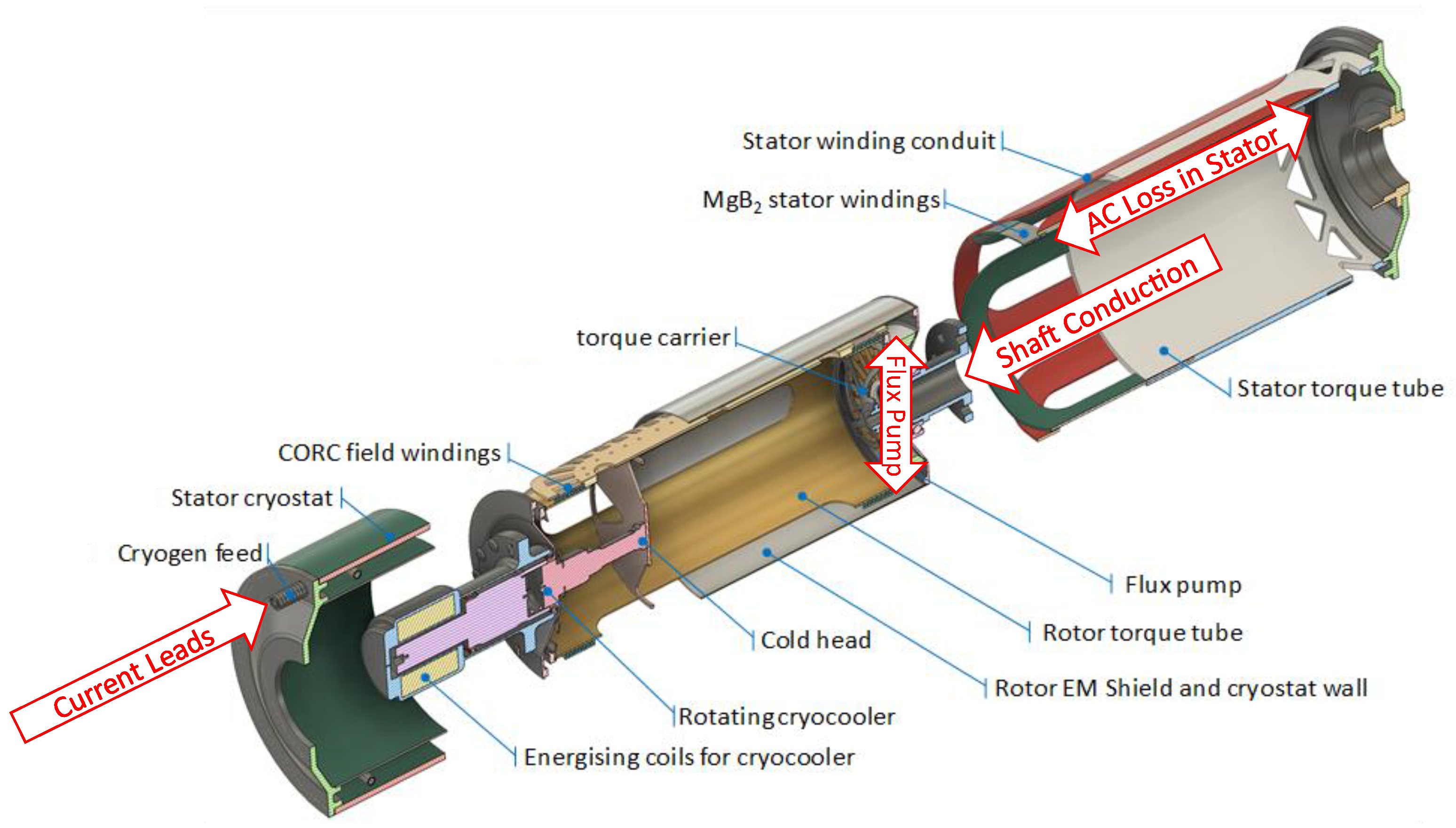
Figure 1 shows our proposed layout of a superconducting motor rotor with a cryocooler directly coupled to the rotor. We have also investigated an alternative, stationary cryocooler architecture [22] with helium circulation, but the requirements are similar. The rotor and stator windings are each contained in separate cryostats, vacuum-insulated from ambient conditions. The airgap between rotor and stator, bearing systems, and the energizing coils for the cryocooler will operate at ambient temperature or higher. The components of the expected rotor heat budget are itemized in Table 1.
As mentioned, our analysis assumes that the rotor coils are excited using an HTS dynamo flux pump [23], which removes the requirement for brushes and cryogenic current leads in the rotor system. Instead, a small amount of electrical power (order 100 W) is needed on the ambient-temperature part of the rotor. If we set a 4 mm gap between the dynamo spindle (at 300 K) and the main rotor cold body (at 50 K), per [23] radiant losses in the order of 0.5 W are expected. The heat budget for a 3 MW motor’s rotor is thus estimated to be 27.5 W of cooling at 50 K. A generous safety margin on cooling power is required as the motor must run even if something is not running perfectly. A 100% safety margin would mean a target refrigeration capacity of 55 W at 50 K. This figure is similar to the 50 W at 50 K refrigerator proposed by Dyson for the same application [24].
2.2. Stator Cooling
The components of the stator cooling budget are itemized in Table 2.
If the total heat load is 1.636 kW at 20 K, with a 100% margin the refrigerator target would be 3.272 kW at 20 K.
2.3. Motor Physical Size
For this analysis, the motor size is taken from the current design of the 3 MW demonstration to be made by the Robinson Research Institute [25] which has the motor 650 mm long, 350 mm in diameter, and weighing 150 kg. It would sit in a fan with 2.7 m diameter shroud. The 3 MW fan is expected to produce around 20 kN of thrust at take-off, so an airplane would need 13 fans to match two CFM56 engines.
3. Heat Sink Options
In any refrigeration system, the performance is driven by the two temperatures that the heat must be transferred between. In our motor, we have stated that heat will be sourced at 20 K in the stator and 50 K in the rotor. For each of these, three heat sink options are considered in this paper.
Option 1 is an ambient heat sink, where the refrigeration system rejects heat to the ambient air outside the aircraft. The nominal heat sink temperature is 300 K, although it is recognized that on a hot day on the tarmac this could be as high as 350 K, and as low as 230 K (−43 °C) when cruising at altitude.
The second and third options take advantage of the proposals to use cryogenic fuels on electric thruster aircraft. Batteries are not currently a viable energy source for larger aircraft such as the A320, so fuel cells or turbogenerators using cryogenic liquid fuels with much higher specific energy are proposed as the source of electricity.
Option 2, therefore, is to use liquid methane, (or Liquified Natural Gas—LNG) as the heat sink. LNG has been proposed in a number of studies [26] as a low carbon fuel for aircraft. LNG as a fuel is likely to be pressurized above ambient to allow transfer from the tank without pumping, and at 1 bar gauge pressure its saturation temperature is 120 K, so this will be used as the heat sink temperature.
Option 3 is liquid hydrogen (LH2), which has been proposed as a zero-carbon fuel for aircraft and is the preferred energy source for fuel cell powerplants. LH2 has an atmospheric boiling point of 20 K but, like LNG, will likely be stored pressurized so its heat sink temperature is assumed to be 23 K, the saturation temperature for 1 bar gauge pressure. An A320-sized airplane using two CFM 56-5 engines can be estimated to use 2.8 kg/s Jet-A on take-off, and minimum of 0.75 kg/s during approach [16]. Assuming a similar thermal efficiency from a hydrogen powered fuel cell or turbogenerator during these phases, we can estimate approximately 0.85 kg/s H2 on take-off and 0.22 kg/s during approach. The minimum usage amount provides 98 kW of potential heat sinking from the latent heat of the hydrogen boiling alone.
4. Cooling of the Rotor
Option 1, direct cryocooling of the rotor to ambient, would use a Stirling cryocooler of similar configuration to the Sunpower DS30 [27] because of its compactness and good efficiency, but with a higher cooling power. Use of a two-stage Stirling cooler where the first stage cools heat intercepts on the shafts and a radiation shield may improve overall system efficiency at the expense of complexity.
The weight of such a system, scaled off a Sunpower DS30 performance to achieve 55 W, would be 29 kg and require 2.2 kW of input power. These figures are small compared to the weight of the motor and the 3 MW input power of the motor, so direct cooling of the rotor seems practical.
Option 2, LNG as a heat sink, would require a cryocooler stage to achieve 50 K. The low heat sink temperature has the potential to improve the cryocooler’s efficiency as the cryocooling options would then only have to lift heat from 50 K to 120 K.
The Carnot COP between 120 K and 50 K is:
State-of-the-art Stirling cryocoolers achieve 30% of the Carnot efficiency, which gives an overall COP of 0.21.
A Stirling cryocooler, either rotating or stationary, directly cooling the rotor would not need to be as large. Using the COP calculated above, the compressor power would be 262 W, approximately half the input power of the DS30, so half the 6.4 kg weight of the DS30.
We would propose that a portion of the LNG being supplied to the powerplant is diverted to cool the refrigerator’s hot end, and then recombined with the main flow. Ideally, no phase change would occur in the heat exchange process. However, there are numerous failure modes that need to be evaluated and it may be preferable to use a separate circulation loop with an intermediate fluid (gaseous helium, for example) to cool the cryocooler. The weight and complexity of a cryogenic coolant circulation loop would offset the 2 kW of energy and 25 kg per motor weight saved.
Option 3, LH2 heat sink, could also employ direct cooling, or be combined with a cold gaseous helium loop. LH2 can provide cooling to around 25 K without a cryocooler and so the 50 K temperature target will be readily achievable. The only mechanical system would be a circulation pump, which could either be a cryogenic fan or an ambient fan with a counterflow heat exchanger separating the cryogenic and ambient parts. This option becomes very practical in the case where a helium loop is also used to cool the stator. The rotor cooling load is minimal compared with the stator and, being at a higher temperature than the stator, can utilize the outlet flow from the stator cooling.
The practicalities of interfacing the gaseous helium coolant to the spinning rotor are not trivial; however, we have previously proposed a rotor cooling solution using a stationary cold head [22] and it is clear that the cold head in that system could be swapped out with a heat exchanger from the gaseous helium loop. Circulating gas involves pumping and flow losses as well as insulation losses in the lines, although these losses are much less than the 2.2 kW required for an equivalent cryocooler.
The other factor to consider when using a cryocooler is the time required to bring the rotor down to operating temperature. Our scaled DS30-type cooler would take approximately 5 h to cool the cryogenic rotor components (approximately 40 kg of stainless steel and copper) down to 50 K. We think the most likely concept of operations for a cryogenic motor would be to keep it cold at all times, except during maintenance. This parasitic load when the motor is idle on the ground could be fulfilled by ground power and would bring distinct durability gains by dramatically reducing the number of thermal cycles over the life of the motor.
5. Cooling of the Stator
The stator cooling requirements are far more demanding that the rotor. The system needs to remove 2.8 kW at 20 K.
For Option 1, mechanical refrigeration at 20 K, the most efficient options are the Cryomech AL325 and the Turbo Brayton recently developed by Creare [28]. Scaling from the AL325 specifications, 522 kW of compressor power would be required to cool that load, weighing in at 8890 kg. The Turbo Brayton is more efficient, needing 256 kW of compressor power; its weight, however, is unknown.
Given that the aim of superconducting motors is to reduce weight through more compact coils, the weight of a cryo-plant to do the whole job of refrigerating the motor would make it unviable. Adding 8.9 tonnes to a 120 kg motor is not feasible, especially if 13 of these motors are required for take-off, adding 124.6 tonnes to an aircraft whose fully laden take-off weight should be 78 tonnes.
Option 2 is using LNG as a cold sink with mechanical cooling to the target temperature. The stator cooling would benefit from a lower heat sink temperature. The Carnot efficiency between 120 K and 20 K is
This is similar to the Carnot COP of a cryocooler operating from ambient to 50 K, well within the range of Stirling, GM, and Brayton systems. However, there would also be the challenge of a cold compressor. For a best-case scenario, the DS30’s efficiency at 50 K is 12.5% of Carnot, giving a COP of 0.025. Using a similar efficiency, then a Stirling cryocooler rejecting at 120 K would require 112 kW of input power and weigh 1.48 tonnes per motor, or 18.2 tonnes for a complete aircraft. Notably, an A320’s cargo capacity is between 18 and 23 tonnes which infers that the cryo-plant could replace the cargo hold in such an aircraft.
The most practical configuration for this option in an aircraft motor is to have a cryo-plant outside the motor and fan, with a circulating gaseous helium coolant, in which case the rotor cooling would piggy-back off the stator cooling.
While LNG heat sinking of the cryocooler is significantly more complex for a small benefit if cooling the rotor only, it greatly benefits the cooling of the stator. Use of LNG for heat sinking may enable an aircraft to fly, but the commercial viability of the aircraft is compromised as the cryo-plant displaces the cargo capacity of the aircraft.
Option 3 is LH2 as the heat sink for the stator. For a cooling power of 2.8 kW at 20 K and using only the latent heat, the mass flow of LH2 required is 0.093 kg/s, which is 15% of the aircraft LH2 use at cruise. Note that a phase change will definitely be required in this case, and so using an intermediate cooling loop of helium is necessary, with the heat exchangers integrated into the fuel gasifier design.
With the LH2 slightly pressurized and a moderate temperature difference needed to transport heat in a cooling circuit, the coils could be kept at 25–30 K with no mechanical cryocooling. Achieving 20 K would require an additional refrigeration step. With such a small temperature difference, a Joule Thompson refrigerator precooled by the LH2, or a pump lowering the hydrogen pressure in the heat exchanger, would be simple and efficient.
A Joule Thompson (JT) valve in the helium circulation loop, with 0.076 kg/s (required flowrate for a 2 K temperature difference across the stator coils (producing 1 kW of heat), can achieve the required cooling with a 20-bar inlet pressure and atmospheric pressure outlet to cool the HTS coils. The exit temperature of the JT valve would need to be approximately 16 K, allowing 2 K for sensible heating of the gas and 2 K for heat transfer to the gas. The attraction of this solution is that the compression can take place before the LH2 heat exchanger (which has ample capacity) and the high-pressure helium in the heat exchanger will increase heat transfer. The JT valve operating well above the liquefaction temperature of the helium will be reliable, and the component to consider first regarding reliability would be the circulation compressor.
6. The Number of Cryocoolers/Cryo-Plants
A consideration for cryocooling is the number of cryocoolers an airplane should have. The governing factors in this optimization are reliability, redundancy, scalability, and distribution of motors in the aircraft.
The range of cryocooler number is a maximum of two per motor (one for the rotor and one for the stator) and a minimum of one. For an A320-sized aircraft with 13 motors on board this is 26 cryocoolers. A failure in any one of these cryocoolers will result in a motor not being able to run and each motor has the chance of one of two cryocooler failures. Redundancy would have to be in the way of excess thrusters, i.e., something like 13 thrusters on board and needing 12 to take off.
There is a good argument for one cooler per motor. If a fully superconducting motor has two coolers, one for the stator and one for the rotor, and failure of either will stop the motor, then the chance of a motor failure is doubled (assuming the failure chance for each cooler is the same). Having the rotor cooled by the same circuit as the stator (the larger and colder cooler) therefore doubles reliability as well as removing the weight and complexity of the rotor cryocooler.
If the minimum number of cryocoolers for the entire aircraft is one, i.e., a central cryo-plant with a capacity to keep all the motors cold via a cold gas circulation loop, failure of the cryo-plant would mean all engines stop.
The aviation industry likes redundancy. The A320 can safely fly on one engine only (although it would be slower if an engine failed on take-off). The same philosophy should be applied to the cryo-plant, where failure of at least one cryocooler should not affect the ability of the plane to fly. For the cryo-plant options, two would then then be the minimum number of cryo-plants, and the airplane should be able to fly on one of them. This doubles the effective weight of the cryo-plant (it would make the fully superconducting motor using LNG unviable). Three, four, or more cryo-plants, and being able to run with one non-operational reduces the surplus weight of the redundancy as long as the cryo-plants can reroute to ensure all motors get cooled.
7. Conclusions
Mechanical cooling of the stators of superconducting motors on aircraft is not practical. The compressor power required will be in the order of 10% of the motor power and the weight prohibitive, estimated to be 6 tonnes per motor.
Mechanical cooling of the rotor only (with copper stators) is practical using a cryocooler mounted on the motor. The cryocooler then becomes an integral part of the motor.
Use of LNG as a heat sink for the mechanical coolers considerably improves efficiency and weight of the cryogenic refrigerators. The power requirement of the compressors drops to 2.7% of the input power and cryocooler weight drops to around 1000 kg per motor. This makes it a technical possibility but at a weight which is the equivalent of the normal cargo capacity of the aircraft.
Use of LH2 as a heat sink is very viable if the stator coils can be run at 25–30 K, in which case the cryogenic plant reduces to a small heat exchanger and circulating pump. The cooling power available from the H2 boil-off exceeds the need of the superconducting motors by more than a factor of 50, so only a small fraction of the fuel used needs to be intercepted for cooling.
If the final temperature needs to be 20 K, then an additional refrigeration stage needs to be added, rejecting heat to the LH2, but this could well be something as simple as a Joule Thompson valve driven off the circulation pump as the temperature drop is small.
The cryogenics decision path is:
- If the fuel source is not cryogenic and the heat sink is ambient then a mechanical cryocooler can be used to cool a superconducting rotor; the stator must be copper.
- If LNG is a fuel source and can be used as a heat sink then the options are: A superconducting rotor, mechanically cooled plus a copper stator that could be cooled by the LNG to achieve better efficiency; or a fully superconducting motor cooled by a cryo-plant of similar weight to the cargo capacity of the aircraft. The rotor would be parasitically cooled by the stator cooling circuit.
- If LH2 is the fuel source and can be used as a heat sink, the options are: A fully superconducting motor running stator coils around 25–30 K using LH2 as a heat sink and no additional cooling. Gaseous helium would be the circulating fluid and would cool both the stator and rotor. This is the simplest option with the only moving part being a circulating fan. Or a fully superconducting motor running the stator coils around 20 K. A supplementary refrigerator would be needed to reduce the temperature from ~25 K (pressurized LH2 from tank) to 20 K. The refrigerator would have to heat sink into the LH2. The simplest and smallest refrigerator would be a JT valve, with a 20 bar internal circulation pump.
Author Contributions
Conceptualization, A.C., H.W. and R.A.B.; Formal analysis, A.C., G.L. and S.J.; Writing—original draft, A.C., G.L., H.W., S.J. and R.A.B.; Writing—review & editing, A.C., G.L., S.J. and R.A.B.; Supervision, H.W. and R.A.B. All authors have read and agreed to the published version of the manuscript.
Funding
This work was funded by the Ministry of Business, Innovation and Employment, New Zealand, under the Advanced Energy Technology Platform program “High power electric motors for large scale transport”, contract number RTVU2004.
Data Availability Statement
The raw data supporting the conclusions of this article will be made available by the authors on request.
Conflicts of Interest
The authors declare no conflict of interest.
References
- Schwab, A.; Thomas, A.; Bennett, J.; Robertson, E.; Cary, S. Electrification of Aircraft: Challenges, Barriers, and Potential Impacts; NREL/TP-6A20-80220, 1827628, MainId:42423; National Renewable Energy Laboratory (NREL): Golden, CO, USA, 2021. [CrossRef]
- ASCEND. Available online: https://arpa-e.energy.gov/technologies/programs/ascend (accessed on 18 March 2024).
- Available online: https://arpa-e.energy.gov/technologies/programs/reeach (accessed on 18 March 2024).
- European Commission Directorate-General for Mobility and Transport; European Commission Directorate-General for Research and Innovation. Flightpath 2050—Europe’s Vision for Aviation: Maintaining Global Leadership and Serving Society’s Needs; European Commission Publications Office: Luxembourg, 2011. [Google Scholar]
- Watson, G. Rolls Royce All-Electric Aircraft Breaks World Records; BBC News: London, UK, 2021. [Google Scholar]
- Loxton, B.; Uchida, J.; Crane, S. First Flight of the eCaravan—MagniX’s All-Electric Cessna 208B Technology Demonstrator. In Proceedings of the 53rd SFTE International Symposium, London, ON, Canada, 24–28 October 2022. [Google Scholar]
- Haran, K.; Kalsi, S.; Arndt, T.; Karmaker, H.; Badcock, R.; Buckley, B.; Haugan, T.; Izumi, M.; Loder, D.; Bray, J.W.; et al. High power density superconducting rotating machines—Development status and technology roadmap. Supercond. Sci. Technol. 2017, 30, 123002. [Google Scholar] [CrossRef]
- Armstrong, M.J.; Blackwelder, M.; Bollman, A.; Ross, C.; Campbell, A.; Jones, C.; Norman, P. Architecture, Voltage, and Components for a Turboelectric Distributed Propulsion Electric Grid; NASA report 20150014237; NASA: Washington, DC, USA, 2015.
- Haugan, T.J.; Sebastian, M.A.P.; Kovacs, C.J.; Sumption, M.D.; Tsao, B.-H. Design and Scaling Laws of a 40-MW-class Electric Power Distribution System for Liquid-H 2 Fuel-Cell Propulsion. In Proceedings of the AIAA Propulsion and Energy 2021 Forum, Virtual, 9–11 August 2021; American Institute of Aeronautics and Astronautics: Reston, VA, USA, 2021. [Google Scholar] [CrossRef]
- Saeidabadi, S.; Parsa, L.; Corzine, K.; Kovacs, C.; Haugan, T.J. A Double Rotor Flux Switching Machine with HTS Field Coils for All Electric Aircraft Applications. IEEE Trans. Appl. Supercond. 2023, 33, 1–7. [Google Scholar] [CrossRef]
- Lee, C.; Kim, S.; Jeong, S. Experimental investigation on a non-flammable mixed refrigerant Joule-Thomson refrigerator for a 100 K cooling temperature. Appl. Therm. Eng. 2024, 246, 122822. [Google Scholar] [CrossRef]
- Amemiya, N.; Yoda, K.; Kasai, S.; Jiang, Z.; Levin, G.; Barnes, P.; Oberly, C. AC Loss Characteristics of Multifilamentary YBCO Coated Conductors. IEEE Trans. Appl. Supercond. 2005, 15, 1637–1642. [Google Scholar] [CrossRef]
- MacDonald, T.; Botero, E.; Vegh, J.M.; Variyar, A.; Alonso, J.J.; Orra, T.H.; da Silva, C.R.I. SUAVE: An Open-Source Environment Enabling Unconventional Vehicle Designs through Higher Fidelity. In Proceedings of the 55th AIAA Aerospace Sciences Meeting, Grapevine, TX, USA, 9–13 January 2017; American Institute of Aeronautics and Astronautics: Reston, VA, USA, 2017. [Google Scholar] [CrossRef]
- European Union Aviation Safety Agency (EASA). 2018 Type-Certificate Data Sheet; No. E.067 for CFM56-5 Series Engines Easa Type Certif. EASA: Cologne, Germany, 2018; pp. 1–12.
- Waters, M.; Schairer, E.T. Analysis of a Turbofan Propulsion System Weight and Dimensions; NASA Technical Memorandum TM X-73,199; NASA: Washington, DC, USA, 1977.
- ICAO Aircraft Engine Emissions Databank. ICAO Aircraft Engine Emissions Databank|EASA (europa.eu). Available online: https://www.easa.europa.eu/en/domains/environment/icao-aircraft-engine-emissions-databank (accessed on 18 March 2024).
- Sugouchi, R.; Komiya, M.; Miura, S.; Iwakuma, M.; Yoshida, K.; Sasayama, T.; Yoshida, T.; Yamamoto, K.; Sasamori, Y.; Honda, H.; et al. Conceptual Design and Electromagnetic Analysis of 2 MW Fully Superconducting Synchronous Motors with Superconducting Magnetic Shields for Turbo-Electric Propulsion System. IEEE Trans. Appl. Supercond. 2020, 30, 1–5. [Google Scholar] [CrossRef]
- Balachandran, T.; Lee, D.; Salk, N.; Haran, K.S. A fully superconducting air-core machine for aircraft propulsion. IOP Conf. Ser. Mater. Sci. Eng. 2020, 756, 012030. [Google Scholar] [CrossRef]
- Grilli, F.; Benkel, T.; Hänisch, J.; Lao, M.; Reis, T.; Berberich, E.; Wolfstädter, S.; Schneider, C.; Miller, P.; Palmer, C.; et al. Superconducting motors for aircraft propulsion: The Advanced Superconducting Motor Experimental Demonstrator project. J. Phys. Conf. Ser. 2020, 1590, 012051. [Google Scholar] [CrossRef]
- Ludbrook, B.M.; Haneef, S.M.; Huang, X.; Gonzales, J.; Moseley, D.; Davies, M.; Duke, O.; Salazar, E.E.; Badcock, R.A. Continuous Fiber Bragg Grating Optical Sensors for Superconducting Magnet Quench Detection: The Effects of Attenuation and Position in the Array. IEEE Trans. Appl. Supercond. 2023, 33, 1–5. [Google Scholar] [CrossRef]
- Huang, X.; Davies, M.; Moseley, D.A.; Ludbrook, B.M.; Salazar, E.E.; Badcock, R.A. Localized Hotspot Detection for Quench Prevention in HTS Magnets Using Distributed Fiber Bragg Gratings. J. Light. Technol. 2023, 41, 7045–7053. [Google Scholar] [CrossRef]
- Caughley, A.; Lumsden, G.; Gschwedtner, M.; Allpress, N.; Rhen, N.R.; Jeong, S. Cooling method for the rotor of a superconducting motor. In Proceedings of the CEC/ICMC 2023 Abstracts & Technical Program, C2oR2B-02, Honolulu, HI, USA, 9–13 July 2023. [Google Scholar]
- Kalsi, S.S.; Storey, J.G.; Brooks, J.M.; Lumsden, G.; Badcock, R.A. Superconducting Synchronous Motor Development for Airplane Applications—Mechanical and Electrical Design of a Prototype 100 kW Motor. IEEE Trans. Appl. Supercond. 2023, 33, 1–6. [Google Scholar] [CrossRef]
- Dyson, W.; Passe, P.; Duffy, K.P.; Jansen, R. High Efficiency Megawatt Motor Rotating Cryocooler Conceptual Design. In Proceedings of the AIAA Propulsion and Energy 2019 Forum, Indianapolis, IN, USA, 19–22 August 2019; American Institute of Aeronautics and Astronautics: Reston, VA, USA, 2019. [Google Scholar] [CrossRef]
- Jeong, S.; Weijers, H.W.; Badcock, R.A.; Gschwendtner, M.; Caughley, A.; Glasson, N.; Singamneni, S.; Jiang, Z.; Hunze, A.; Lumsden, G.; et al. Holistic approach for cryogenic cooling system design of 3 MW electrical aircraft motors. In Proceedings of the AIAA Propulsion and Energy 2021 Forum, Virtual, 9–11 August 2021; American Institute of Aeronautics and Astronautics: Reston, VA, USA, 2021. [Google Scholar] [CrossRef]
- Roberts, R.; Nuzum, S.R.; Wolff, M. Liquefied Natural Gas as the Next Aviation Fuel. In Proceedings of the 13th International Energy Conversion Engineering Conference, Orlando, FL, USA, 27–29 July 2015; American Institute of Aeronautics and Astronautics: Reston, VA, USA, 2015. [Google Scholar] [CrossRef]
- Wilson, K.; Wade, J.; Mansfield, D. Sunpower DS 30 Cryocooler Development. Proc. Cryocoolers 2018, 20, 135–141. [Google Scholar]
- Cragin, K.J.; Zagarola, M.V. Development and Testing of a High-Capacity 20 K Cryocooler. Cryocoolers 2022, 22, 335–343. [Google Scholar]
Figure 1.
Exploded section view of a superconducting motor, with main heat sources indicated (red text).
Figure 1.
Exploded section view of a superconducting motor, with main heat sources indicated (red text).


Table 1.
Heat budget for a superconducting rotor.
| Heat Source | Approximate Magnitude | Mechanism and Comment |
|---|---|---|
| Drive shaft Conduction | 15 W | Conduction, 7.5 W each side |
| Radiation/insulation losses | 3.4 W | Bare vacuum radiation assumed for a 200 mm diameter cylinder 400 mm long with polished metal surfaces |
| Coils | 3.75 W | Joule heating of HTS joints |
| Coolant circulation Viscous losses | 5 W | Helium circulation internal to rotor—room for improvement with optimization of design |
| Flux Pump | 0.5 W | Bare vacuum radiation between 200 mm diameter coaxial disks, 4 mm apart. One polished, one matte |
Table 2.
Heat budget for a superconducting stator.
| Heat Source | Approximate Magnitude | Mechanism and Comment |
|---|---|---|
| Supports | 20 W | Conduction, intercepts possible |
| Radiation or insulation losses | 6 W | Radiation, shielding possible |
| Current leads | 10 W | Conduction and joule heating—intercepts possible |
| Coils with AC | 1 kW [25] | Generated in the coils due to a reversing magnetic field dumping its hysteresis loss into the wire at ~20 K. This value changes with wire type, coil design, and operating temperature and hasn’t been fully defined yet but most calculations are in the order of 1 kW |
| Pumping/Viscous losses | Estimate 600 W 1 | Pumping loss for circulating gas, heat enters system throughout the circuit and is removed by a cryo-plant of some kind |
1 The pumping loss was calculated from a mass flow of helium gas at 20 K to carry 2 kW of heat away from the stator with 5 K temperature rise and losing 3 velocity heads from a 25 mm diameter transfer line.
Disclaimer/Publisher’s Note: The statements, opinions and data contained in all publications are solely those of the individual author(s) and contributor(s) and not of MDPI and/or the editor(s). MDPI and/or the editor(s) disclaim responsibility for any injury to people or property resulting from any ideas, methods, instructions or products referred to in the content. |
© 2024 by the authors. Licensee MDPI, Basel, Switzerland. This article is an open access article distributed under the terms and conditions of the Creative Commons Attribution (CC BY) license (https://creativecommons.org/licenses/by/4.0/).
Share and Cite
MDPI and ACS Style
Caughley, A.; Lumsden, G.; Weijers, H.; Jeong, S.; Badcock, R.A. Cooling of Superconducting Motors on Aircraft. Aerospace 2024, 11, 317. https://doi.org/10.3390/aerospace11040317
AMA Style
Caughley A, Lumsden G, Weijers H, Jeong S, Badcock RA. Cooling of Superconducting Motors on Aircraft. Aerospace. 2024; 11(4):317. https://doi.org/10.3390/aerospace11040317
Chicago/Turabian StyleCaughley, Alan, Grant Lumsden, Hubertus Weijers, Sangkwon Jeong, and Rodney A. Badcock. 2024. "Cooling of Superconducting Motors on Aircraft" Aerospace 11, no. 4: 317. https://doi.org/10.3390/aerospace11040317
Note that from the first issue of 2016, this journal uses article numbers instead of page numbers. See further details here.