
Glass Composition for Coating and Bonding of Polycrystalline Spinel Ceramic Substrates

Department of Chemistry, Ben-Gurion University, Hashalom St. #1, P.O. Box 653, Beer-Sheva 84105, Israel
Ceramics 2024, 7(1), 101-114; https://doi.org/10.3390/ceramics7010008
Submission received: 29 November 2023
/
Revised: 8 January 2024
/
Accepted: 16 January 2024
/
Published: 25 January 2024
(This article belongs to the Special Issue Transparent Ceramics—a Theme Issue in Honor of Dr. Adrian Goldstein)
Abstract
:Design considerations of the lead-based glass composition was broadened beyond the two known criteria of matched index of refraction and thermal coefficient of expansion to include previous studies of thick film materials. Five criteria for the glass-design composition were used: matched index of refraction and thermal coefficient of expansion, components (MgO and Al2O3) to slow down dissolution of spinel (MgAl2O4) into the glass, non-crystallizing glass in a broad temperature range and glass with good chemical durability. Synthesis and characterization of glass, glass paste preparation and its application to spinel substrates to form coating and bonding and optical characterizations in the UV, VIS and IR of coated, uncoated, and bonded spinel substrates of two commercial sources are described. Enhancement of transmittance exceeding the theoretical value of polished spinel was found for the first time when glass coating was applied to a ground face of semi-polished spinel.
1. Introduction
The cost of production of ceramic parts in current technologies, and specifically, in single crystal sapphire (Al2O3) and ceramics comprising spinel structures (MgAl2O4), is high due to an expansive processing and polishing procedure. In ceramic polishing, the expansive machining or polishing of the surfaces is unavoidable in most cases in which the end product is required to transmit light. The difficulties involved in polishing ceramics and particularly spinel structures can result in a large fraction of the total cost being associated with surface finishing and polishing. To reduce these high polishing and finishing costs, a refractive index matched glass coating is applied to the hard inorganic substrates to render them transparent. The fired glass coating can be polished if required using conventional polishing methods which are very cheap. The feasibility of coating a hard inorganic material such as sapphire with a lead-based glass frit was demonstrated on small tiles [1] and on large area windows which were coated and bonded with glass [2]. The selection criteria for the glass compositions used for coating in the cited above works were index of refraction and probably linear coefficient of expansion matching to the ceramic substrate. Are these criteria sufficient for lead-based glass for coating sapphire and spinel? The answer is no if we consider studies in thick film technology and materials. High lead-based glasses which are used in thick film materials are very reactive and interact with the ceramic substrates (96% Al2O3, 99% Al2O3, sapphire) at moderate temperatures. These glasses dissolve substantial amount of the substrate [3,4] during firing at Birox® profile (fast ramp to 850 °C dwell of 10 min at 850 °C, fast cool down to room temperature, the whole profile is 30 to 60 min). Dissolution of the substrates into the glass changes the properties of the glass.
Spinel ceramic (MgAl2O4) is a durable, isotropic material with outstanding optical and mechanical properties and has been the subject of intensive research efforts in the last 70 years [5,6,7,8,9]. Some of its diverse applications were reported in reference [5] and other applications are collected in references [10,11,12,13,14,15,16,17,18,19].
The size of the substrates synthesized was scaled up to large windows [11,12] that can be used for transparent armor as a strike-face layer. Large substrates have coarse-grained structure; evaluation [20] “showed that, under the same loading conditions, the flexure strength of coarse-grained spinel was approximately 75 MPa while the strength of a fine-grained (i.e., <25 μm), sintered spinel was close to 200 MPa”. High-strength substrates are still limited in size, and a suitable bonding material is required to make large windows.
Low-fire high-barium leadless borosilicate glass frit, Pemco-626, was used to coat unpolished and polished spinel substrates [21]. The glass has TCE similar to spinel, measured TCE 7.3 × 10⁻⁶/°C, calculated [22] TCE 7.6 × 10⁻⁶/°C, but the index of refraction is not matched to spinel. The glass adhered very well to the spinel, and coating improved the transparency of unpolished spinel, but transparency is still low. Recently, a lead borosilicate glass composition was suggested for joining (edge joining) spinel tiles [23]. The glass matched the index of refraction, and TCE to spinel and joining was performed at 760 °C.
This study is based on a patent application [24]; it deals with modified lead silicate composition (melted in 2015), which contains Al2O3, MgO, ZnO and TiO2 in addition to PbO and SiO2. Five criteria were used to design the composition: index of refraction and TCE matched to spinel, glass ingredients (Al2O3, MgO) to slow down dissolution of spinel into the glass, non-crystallizing glass composition at a broad temperature range, and a durable glass composition. The paper also details synthesis of glass, glass paste, measurements of optical properties of coated and uncoated spinel substrates, edge, and face-to-face bonding of spinel tiles. In addition, to lead-based glass, the paper also details the synthesis and some properties of leadless-glass compositions based on an La2O3-MgO-ZnO-Al2O3-B2O3-SiO2 system.
2. Experimental
Analytical reagent grade SiO2, PbO, MgO, ZnO, TiO2, Al (OH)3 and Hammond Lead glass B15 powder (composition in wt.% SiO2-34; PbO-63:Al2O3-2: TiO2-1) were used as batch materials. Batch materials were mixed in a polyethylene container then placed into Pt crucible and heated in a box furnace at 1200–1400 °C to melt and homogenize for 0.5 to 3 h. Glass melt was poured into water to obtain glass frit. Glass frit dried in the oven at 150 °C, and then it was ball milled with alumina grinding media (200 g raw frit and 200 mL isopropanol) for 24 h. After separation of the alumina grinding media, the slip was passed through 325 and 400 mesh stainless screens and let evaporate in the hood, and then they were dried in an oven at 150 °C for several hours. The batch size was about 500 g and four batches were melted.
Before fritting, the melt was cast into pre-heated box-shaped stainless-steel modular molds to form glass bars of 5 × 0.8 × 0.8 cm3. The bars were annealed for 0.5 h in an electric box furnace. Annealing temperature (Tan) was estimated according to the formula Tan = Tg + 10 °C. The glass bars were cut and polished to produce parallel faces. Linear coefficients of expansion were in the temperature range of 25–300 °C (TCE25–300); the glass transition temperatures (Tg) and the dilatometric softening points (Td) were measured with an Orton dilatometer, model 1000D, at a heating rate of 3 °C/min. The measurement accuracy of the linear coefficient of expansion was ±10%. Part of the expansion bar (after annealing) was cut to provide a small piece, which was polished and used to measure the index of refraction at the sodium D line. Index of refraction was measured with Atago company, Japan refractometers models 4T and DR-A1.
Glass compositions of the system La2O3-MgO-ZnO-Al2O3-B2O3-SiO2 were synthesized from analytical reagent grade H3BO3, SiO2, Al (OH)3, ZnO, MgO and La2O3. MgO and La2O3 were first heated at 1000 °C for one hour to decompose hydroxides and carbonates which form in storage. Batch ingredients were melted in Pt crucible at the temperature range of 1350 to 1450 °C and kept at peak temperature for 1 to 3 h, and then glass bars were cast as described above and annealed at 660 °C. Batch size was about 50 g. Thermal expansion and the index of refraction were measured as described above. Glass powder was made by crushing the glass bar to a coarse powder, and then the coarse powder was milled in a Spex sample prep. model 8000M (Metuchen, NJ, USA) for 60 min.
The glass paste consists of inorganic particulate (glass powder) and organic materials. The organic materials used consisted of a mixture of diethylene glycol dibutyl ether, terpineol, and ethyl cellulose. The ingredients of the paste are weighed together in a container and vigorously mixed to form a uniform blend; then, the blend is passed through dispersing equipment, such as a Muller, to achieve a good dispersion of particles. Preparation of the glass paste can also be done by grinding the paste ingredients (glass powder 70%, solvents (terpineol and diethylene glycol dibutyl ether) 20% and medium 10% (medium is a solution of ethyl cellulose10% in terpineol 45% and diethylene glycol dibutyl ether 45%)) in an agate mortar and pestle. For a larger quantity of paste a three-roll mill can be used. In this study the paste was applied to the spinel substrates manually by spreading it with a spatula; for large area substrates, a screen printer maybe used.
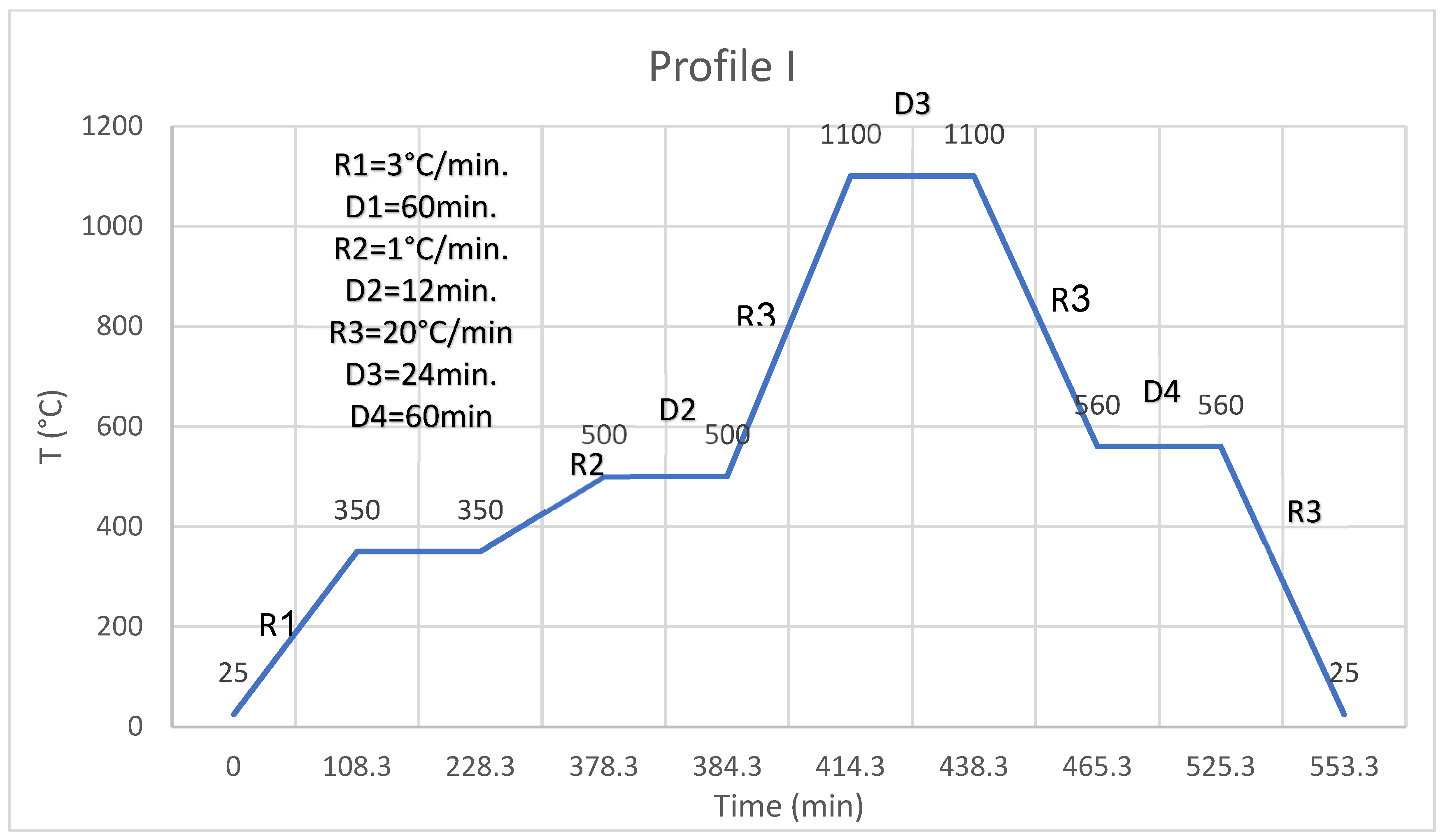
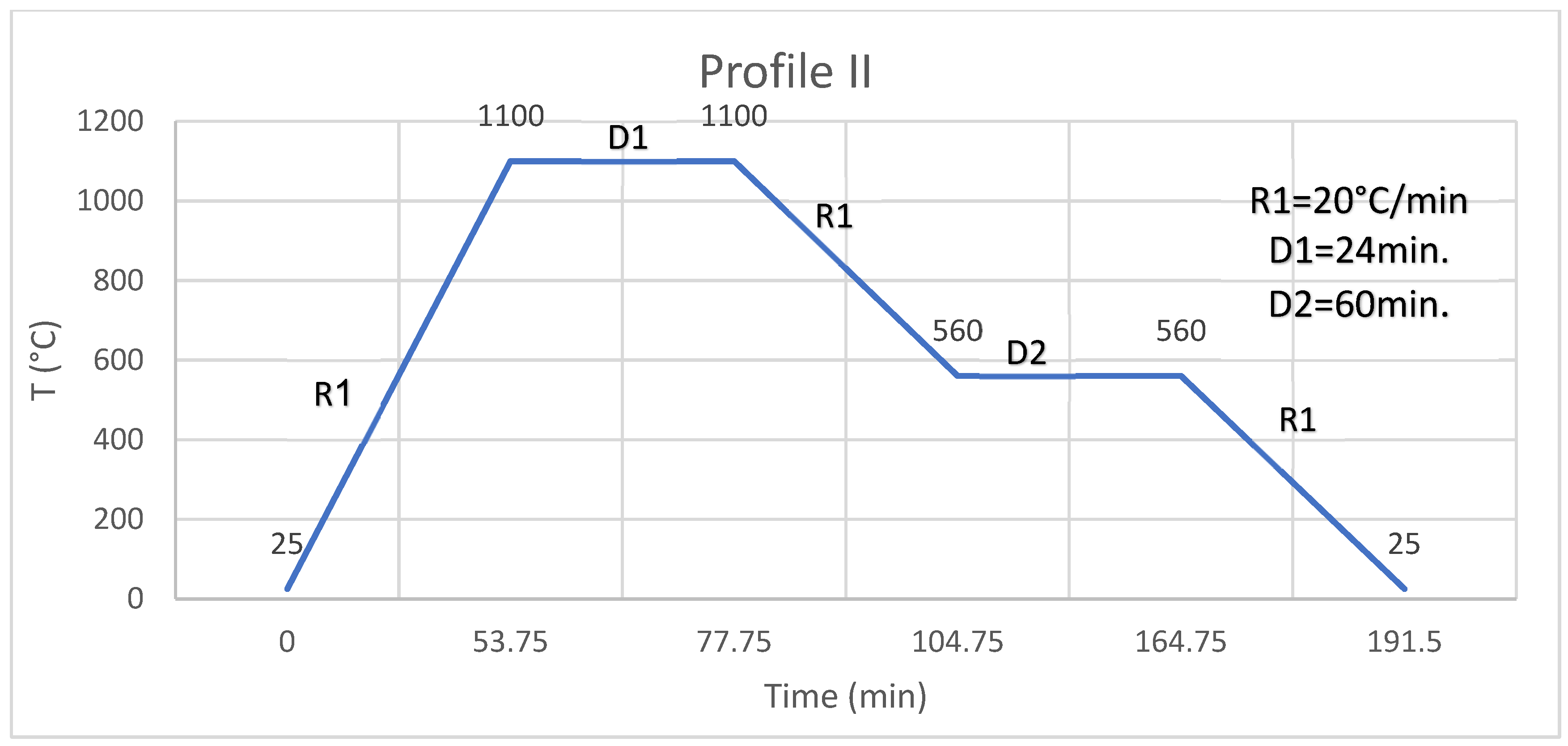
The coating is a one-stage process; paste is applied (thickness of coating is controlled using the weight of the paste, and the thickness of the fired glaze is about 50 microns) to the surface or edge of a substrate (two types of commercial spinel substrates were used: one made by Ceramtech and the second by Rafael companies), and paste is spread to cover the whole face or the edge, and then the coated substrate is left at room temperature so the paste can level. After leveling, the coated substrate is heated in an oven at 150 °C for 30 min to evaporate a large fraction of the solvents to obtain dry paste (the dry paste still contains the ethyl cellulose and a small part of the solvents). After drying, the coated substrate is fired in profile I (Figure 1). Profile I has two slow-heating segments which allow evaporation, pyrolysis, and burning of the organic materials, and then fast ramping at 20 °C/min to 1100 °C, dwelling of 24 min at 1100 °C then cooling the segment at 20 °C/min to 560 °C, and then, dwelling for 1 h to anneal the glass coating and then cooling it down at 20 °C/min to room temperature. After profile I, a glazed surface or edge is obtained. The bonding or the joining of two faces or edges is a two-stage process; the faces or edges of two substrates are processed as described above using profile I to obtain two glazed faces or edges. Glazed faces or edges are placed one on top of the other, glazed faces or edges are in contact and fired in profile II (Figure 2). Profile II has only fast ramping at 20 °C/min to 1100 °C, dwelling of 24 min at 1100 °C, then cooling of the segment at 20 °C/min to 560 °C, and then dwelling for 1 h to anneal the glass and then cooling it down at 20 °C/min to room temperature. After profile II, two bonded substrates at faces or edges are obtained.
Surface area was measured using the BET method using Quantachrome Nova Touch LX3 (FL, USA). Surface area of ball-milled glass powder was 1.63 m2/g.
Spectra in the UV-VIS and IR ranges were measured with Jasco V-530 and Thermo Nicolet 6700, respectively.
3. Results and Discussion
Table 1 presents the composition, in mole% and wt.%, of the glass of this study. According to the design criteria, the composition contains about 6 mole% of alumina and magnesia to slow down dissolution of spinel into the glass. The references cited [3,4] conducted a comprehensive study on the lead-based-glass compositions and analyzed the alumina content dissolved into the glass and correlated it with the glass composition. As the alumina content in the lead silicate increased, the glass dissolved less alumina from the substrate. The following citation is from the conclusions section of reference [4]: “These results suggest that the glass frit component of a resistive paste should contain an adequate amount of alumina in order to prevent further dissolution, to get a constant composition in the film, and so, uniform electrical properties of thick-film resistors”. This supports the design criteria. Spinel is a source of alumina and magnesia. Inclusion of alumina and magnesia in the glass will slow or prevent dissolution of spinel in the glass. This assumption also follows from Le Chatelier’s principle. Inclusion of alumina and magnesia also raises the viscosity of the glass, and higher glass viscosity slows down the kinetics of spinel dissolution into the glass.
Lead oxide controls the viscosity and increases the refractive index, and titania increases the index of refraction and the glass durability. Zinc oxide was added to lower thermal expansion and to add another modifier to suppress crystallization.
The lead-based glass of Table 1 is unique: it does not crystallize on repeated heating at 1100 °C; it has low viscosity at high temperatures; it has TCE and Nd matched to spinel; and very good chemical durability.
Table 2 collects the glass transition Tg, dilatometer softening point Td, linear coefficient of expansion in the temperature range of 25–300 °C, TCE25–300, and the refractive index Nd of four glass batches melted. The calculated [22] TCE is 5.9 × 10⁻⁶. The calculated TCE is in good agreement with the measured values. All four batches have consistent values of Tg, Td, and Nd.
Glass compositions based on the La2O3-MgO-ZnO-Al2O3-B2O3-SiO2 system are shown in Table 3. Properties of the glasses of Table 3 are collected in Table 4. The lanthanum-based glasses prepared have high Tg, TCE compatible with spinel, and Nd like spinel. However, the lanthanum-based system crystallizes when heated above 850 °C and is not suitable for coating spinel.
Figure 1 and Figure 2 were detailed in the experimental section. The dwell of 24 min at the high temperature of 1100 °C, well above the Tg, allows the release of gas bubbles from the glass coating because of the low viscosity of the glass at this temperature. Release of gas bubbles improves the optical quality of the glass coating.
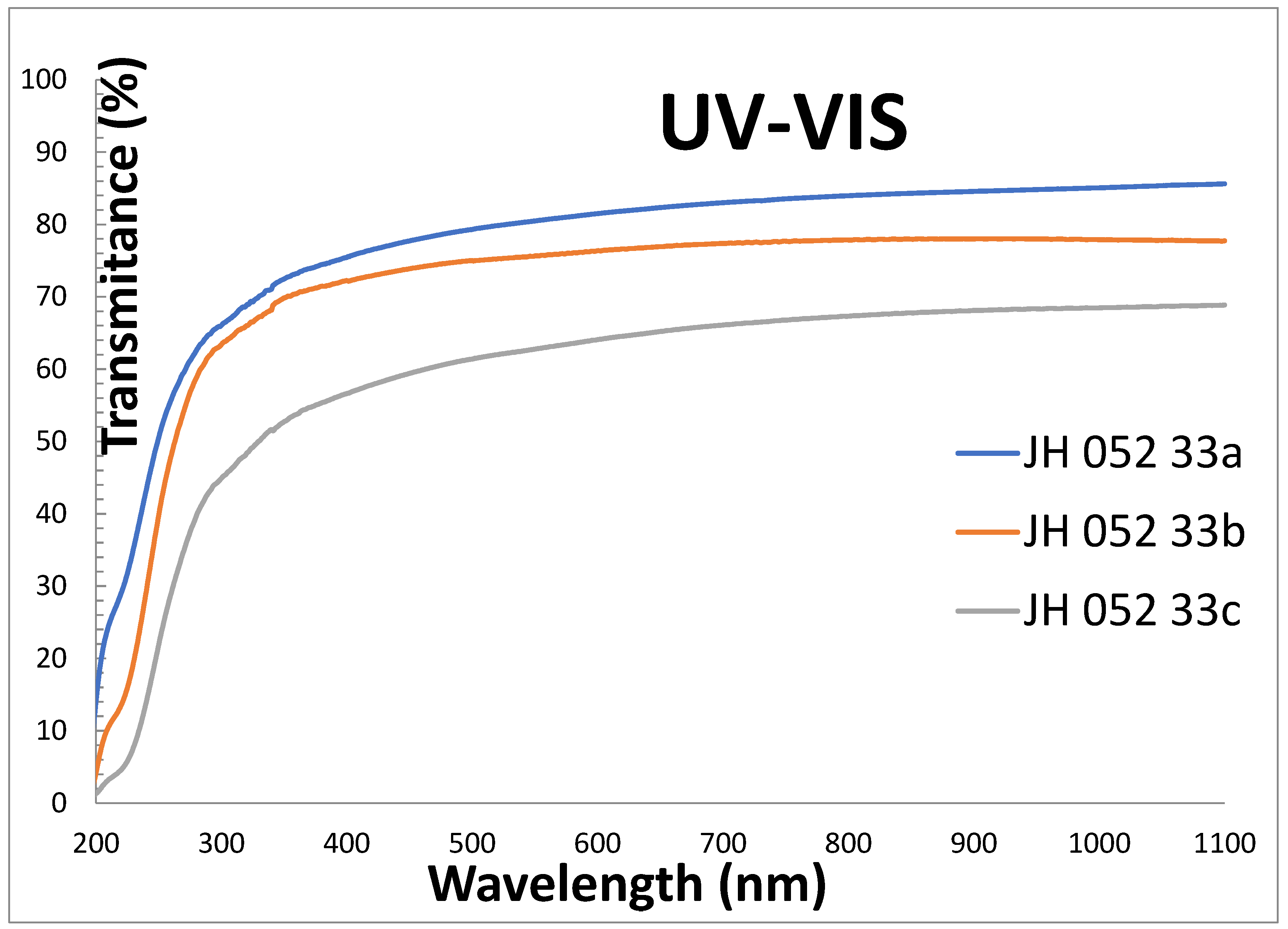
Figure 3 shows the transmittances of polished substrates of Rafael company in the UV-VIS range: -33a is single substrate (two reflections), -33b is two substrates stacked together with cellotape on the edges (four reflections), and -33c is three substrates stacked together with cellotape on the edges (six reflections).The single substrate (-33a) is transparent in the UV down to 200 nm, and its transmittance in the VIS is high, almost like the theoretical value 86.8.
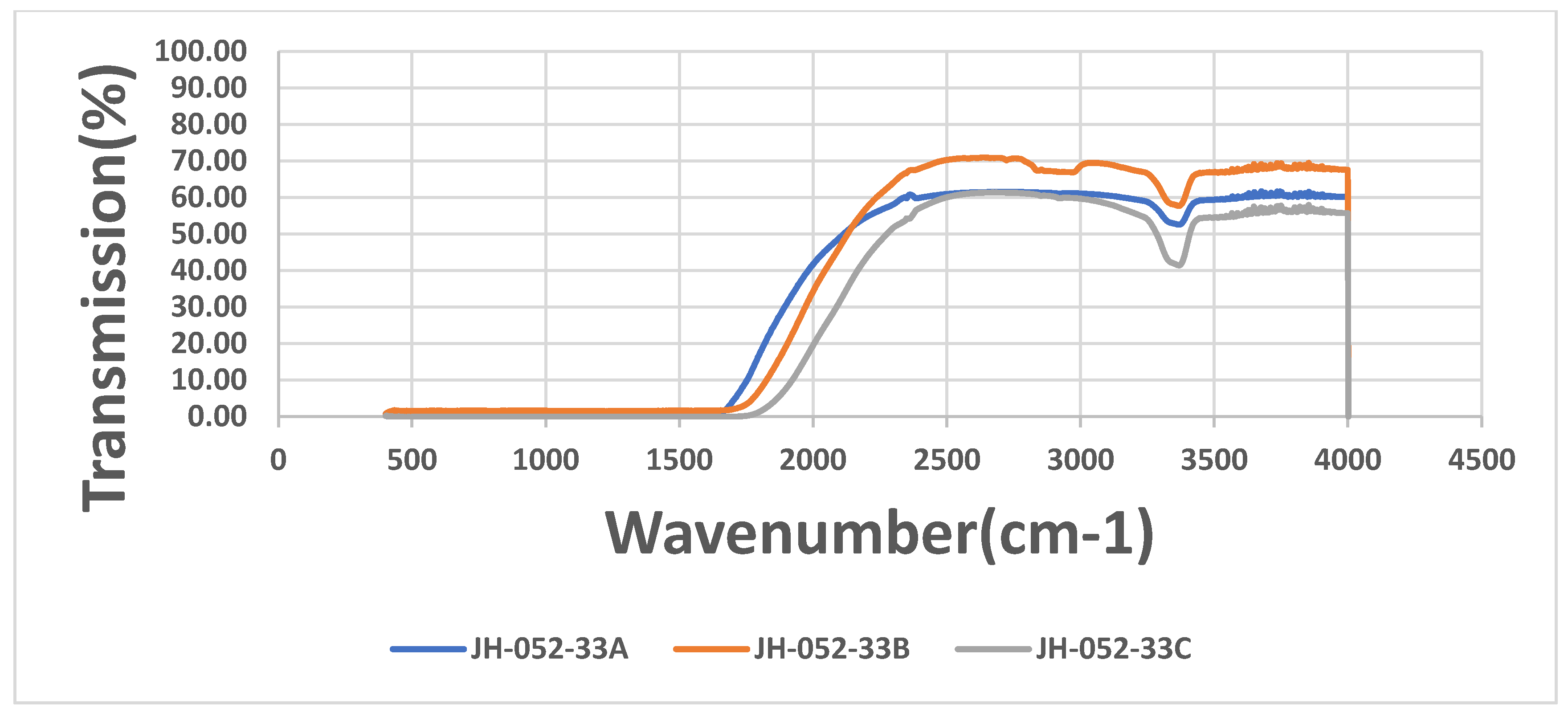
Figure 4 shows the IR transmittances of the substrates of Figure 3. The figure shows a small absorption band around 3380 cm−1, which is probably the absorption of OH groups in the ceramic and an indication of a processing stage which involved water (milling in water) during the preparation of the spinel.
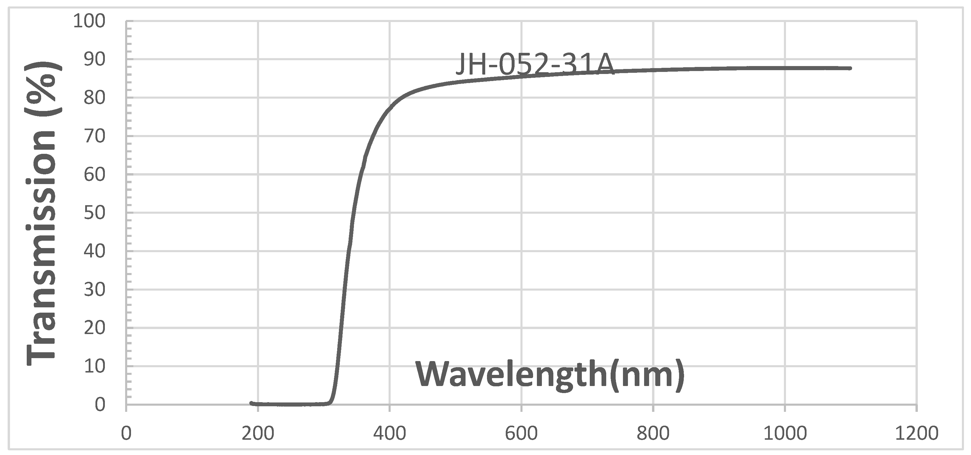
Figure 5 shows the transmittance in the UV-VIS range of coated semi-polished spinel of Rafael. Figure 5 shows high transmittance in the VIS range that is larger than that of a polished substrate. This result is unexpected because a glass coating on a polished spinel surface usually decreases the transmittance; see figure "transmittances of polished spinel (JH-052-100A) and polished spinel coated with glass on one face (JH-052-100B1)". The surface of the spinel (ground) may be the source of enhanced transmission shown in Figure 5, but further studies are required to better understand this unusual behavior.
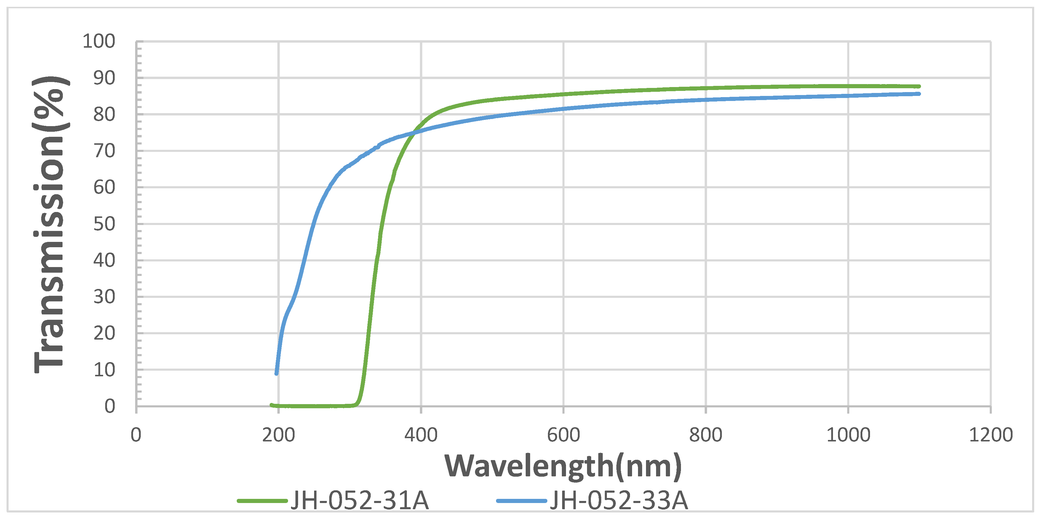
The comparison of the transmittances of polished (-33a) and coated semi-polished (-31a) spinel substrates in the UV-VIS range is shown in Figure 6. Figure 6 shows that the uncoated polished spinel (-33a) is transparent in the UV almost down to 200 nm. The coated semi-polished spinel (-31a) has a total absorption of up to about 310 nm, and its transmittance in the VIS is larger than the theoretical value (86.8%). The absorption in the UV is due to an allowed 1S0 to 3P1 transition of Pb2+ ions in the glass. The transmittance of the semi-polished coated spinel (-31A) is larger than that of the polished spinel (-33A).
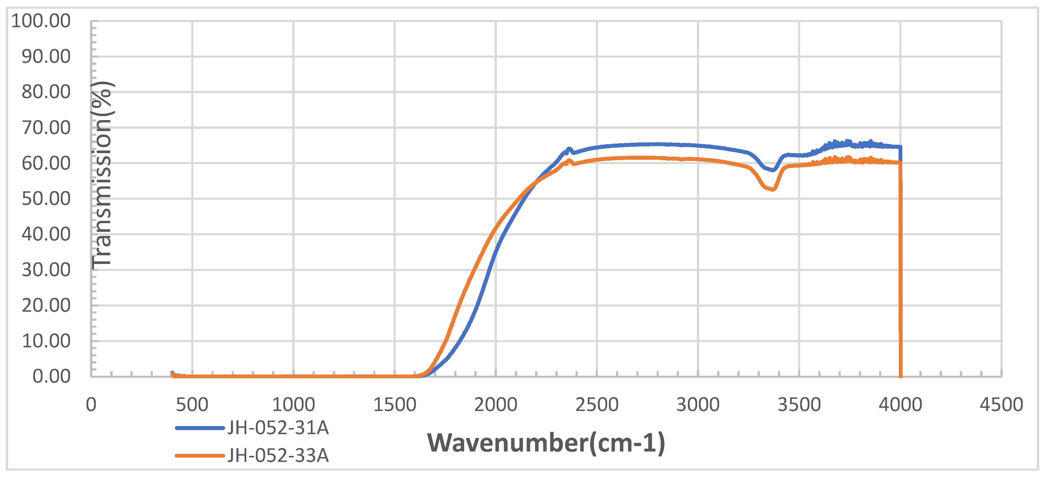
The comparison of the transmittances of polished (-33a) and coated semi-polished (-31a) spinel substrates in the IR range is shown in Figure 7. Figure 7 shows the IR transmittances of Figure 6’s substrates; the glass-coated semi-polished spinel (-31a) has better transmittance than the polished (-33a) substrate and the glass coating did not add new absorption bands, and only below 2177 cm−1 did the polished substrate have slightly better transmittance.
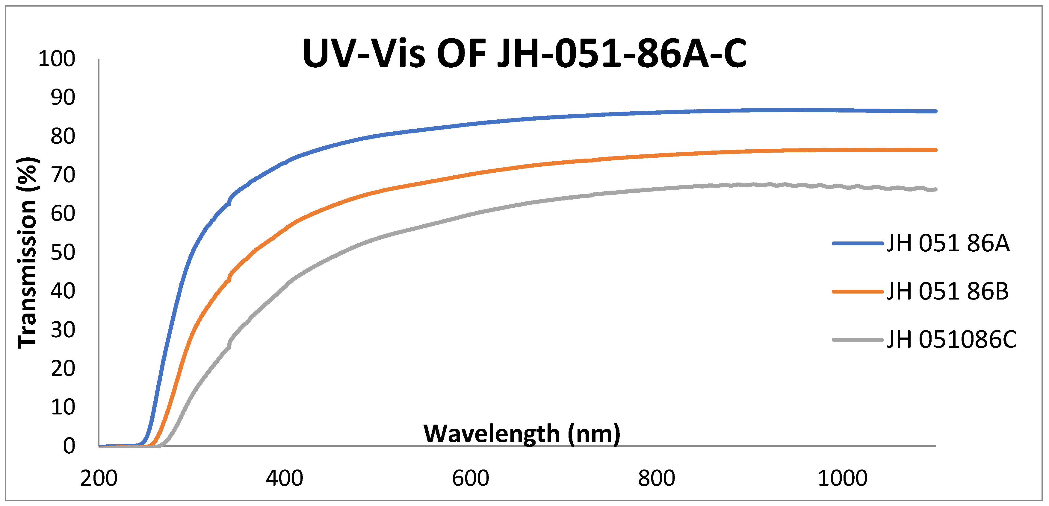
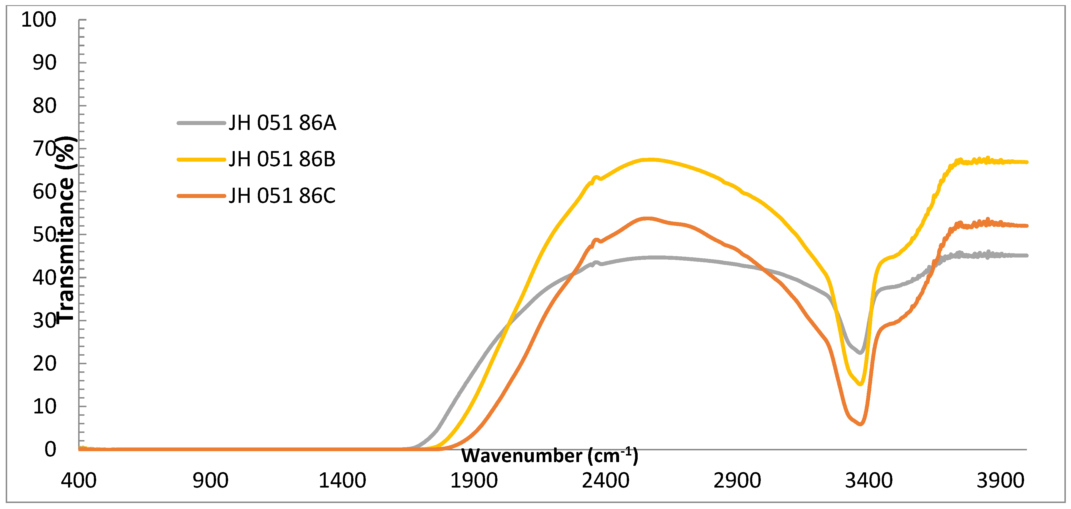
Figure 8 and Figure 9 show the transmittances of polished Ceramtech substrates at the UV-VIS and IR ranges, respectively. In the figures, the transmittance of a single substrate (two reflections), two substrates stacked together with cellotape on the edges (four reflections), and three substrates stacked together with cellotape (six reflections) on the edges are shown to compare them to Figure 3 and Figure 4 which show the substrates of Rafael. Ceramtech substrates (Figure 8) have absorption in the UV of up to 245 nm; Rafael’s substrates have no absorption in the same wavelength range. The transmittances of Ceramtech’s in the VIS are similar to those of Rafael’s substrates. Figure 9 shows that Ceramtech spinel has large absorption bands in the IR at 3370 cm−1 and a shoulder at 3550 cm−1. The absorption bands in the IR are the absorption of OH groups in the ceramic and an indication of a processing stage which involved water (milling in water) during the preparation of the spinel.
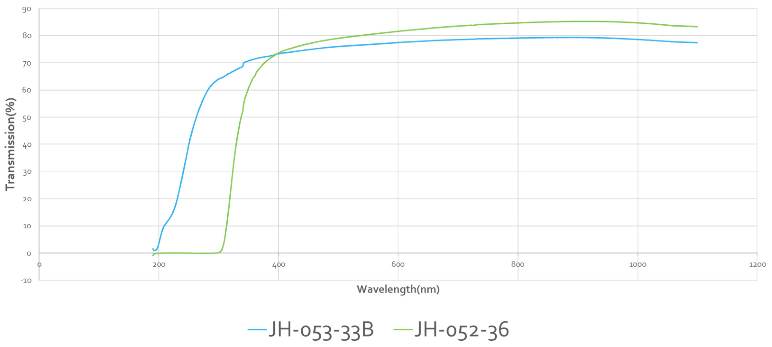
Figure 10 shows a comparison of transmittances of Rafael glass bonded (two polished substrates, face-to-face bonded with glass) with two polished spinel substrates stacked together with cellotape on the edges. The glass-bonded (-36) spinel has the expected absorption in the UV, but its transmittance at the VIS is high and similar to the transmittance of a single polished spinel. The transmittance of the stacked polished spinel is lower in the VIS because of four reflections; the glass-bonded spinel behaves like it has only two reflections.
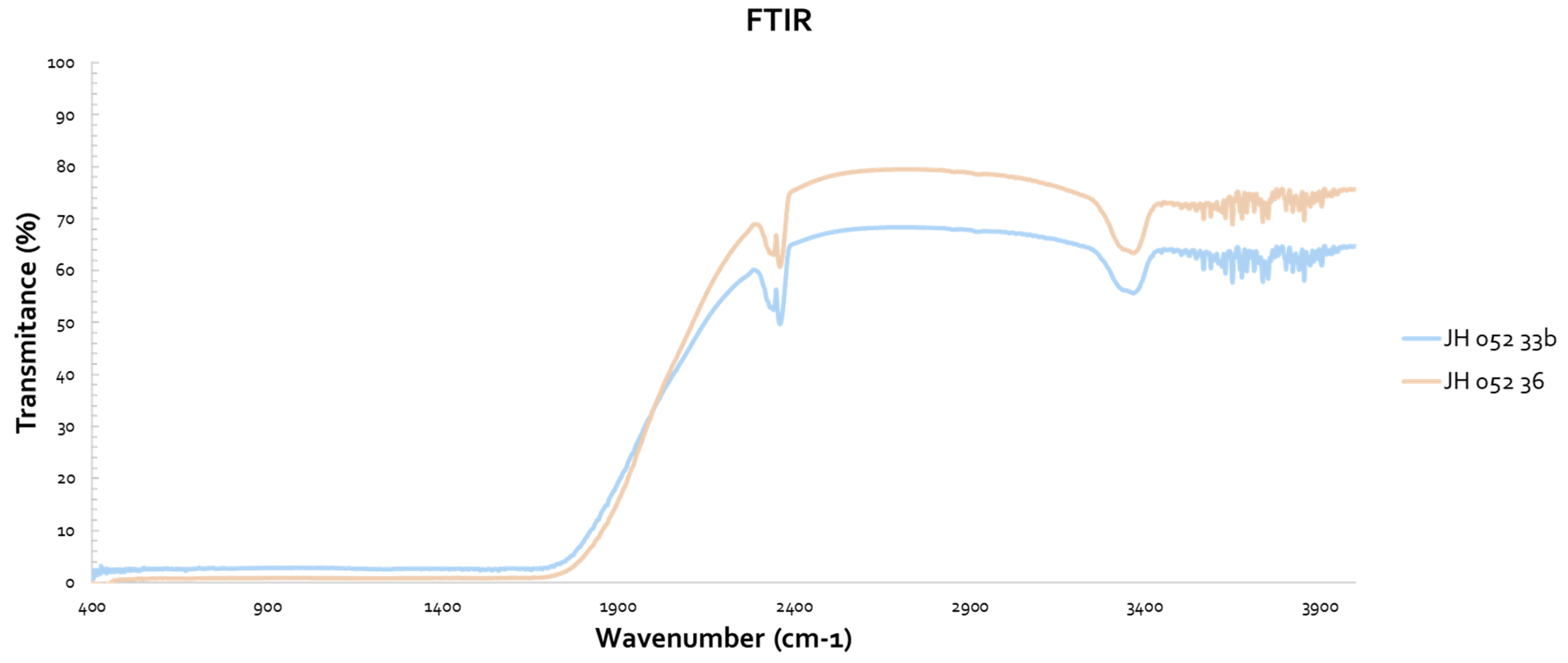
Figure 11 shows the IR spectra of the substrates of Figure 10 (Rafael). The glass-bonded spinel (-36) has better transmittance in the IR, and the glass did not have any noticeable absorption bands.
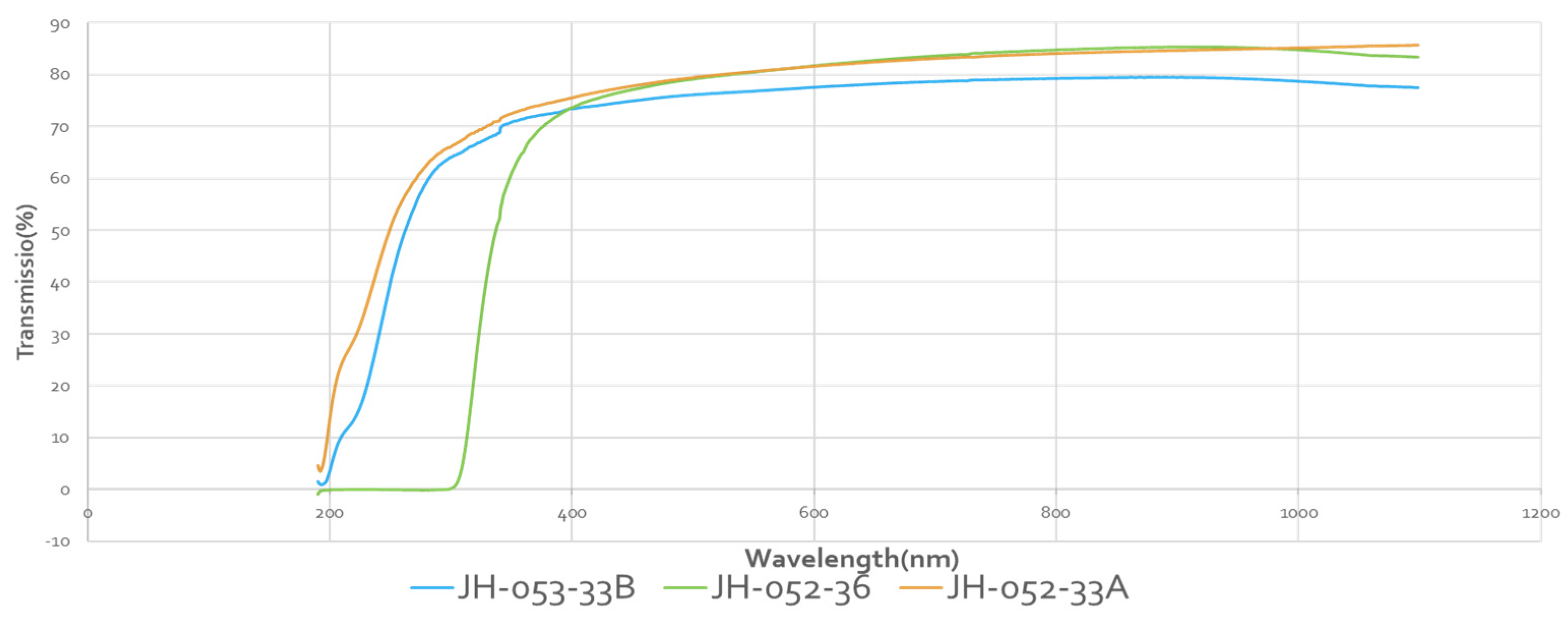
Figure 12 shows the UV-VIS transmittances of Rafael polished substrates:
-33A is single spinel, 0.8 cm thick; -33B is two spinel substrates taped together with cellotape on the edges, 1.6 cm thick; and -36 is two substrates face-to-face bonded with glass, 1.6 cm thick. The two-glass-bonded (-36) unit has VIS transmission similar to a single spinel, and almost identical. The cellotape-stacked-two-spinel unit has a lower transmission in the VIS because of the four reflections.
JH-052-33 A: polished spinel 0.8 cm thick.
JH-052-33B: two polished spinels taped together at the edges 1.6 cm thick.
JH-052-36: two face to face glass bonded spinels 1.6 cm thick.
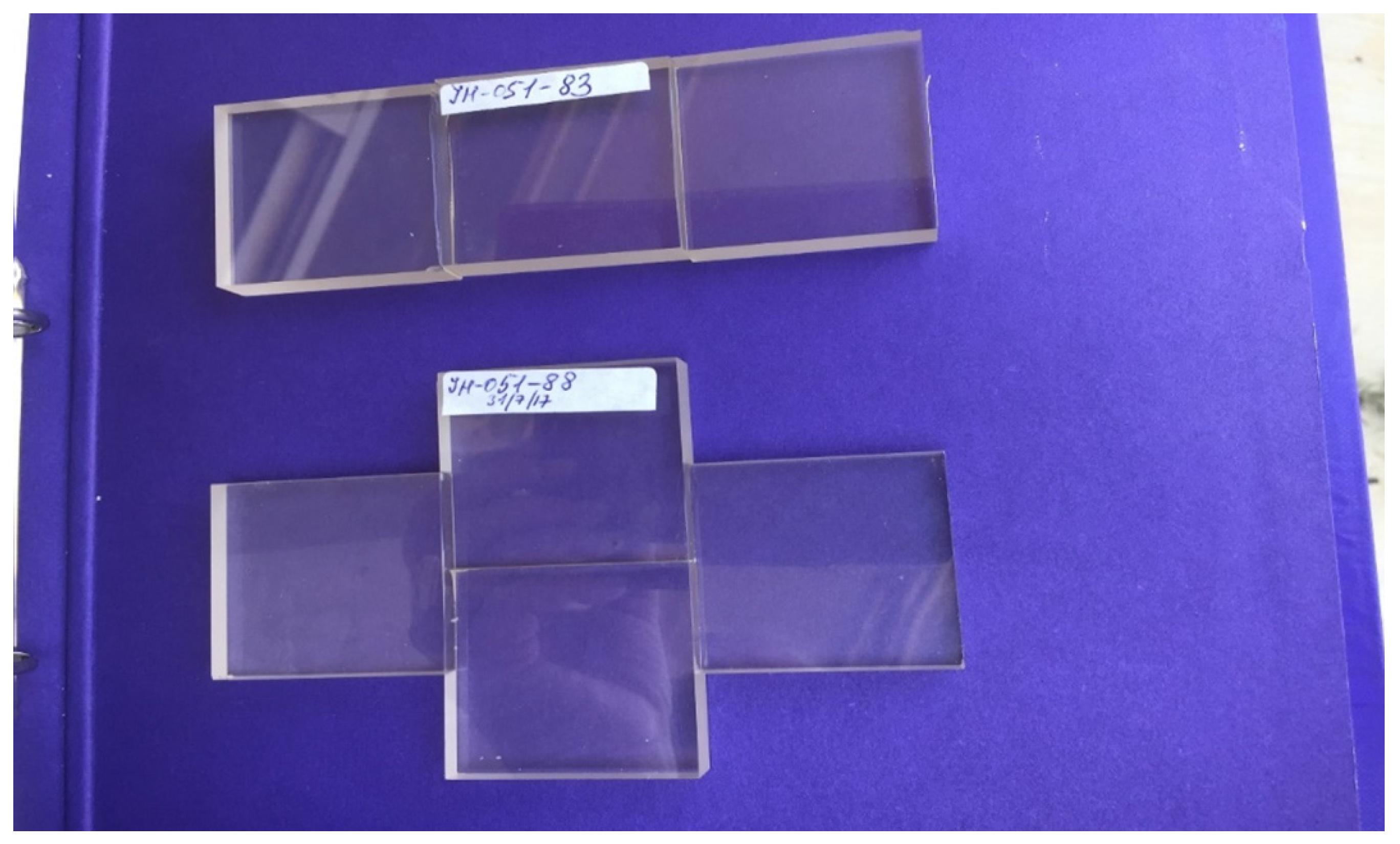
Figure 13 and Figure 14 are pictures of edge-bonded spinels (Ceramtech) to demonstrate formation of a large area substrate from small substrates.
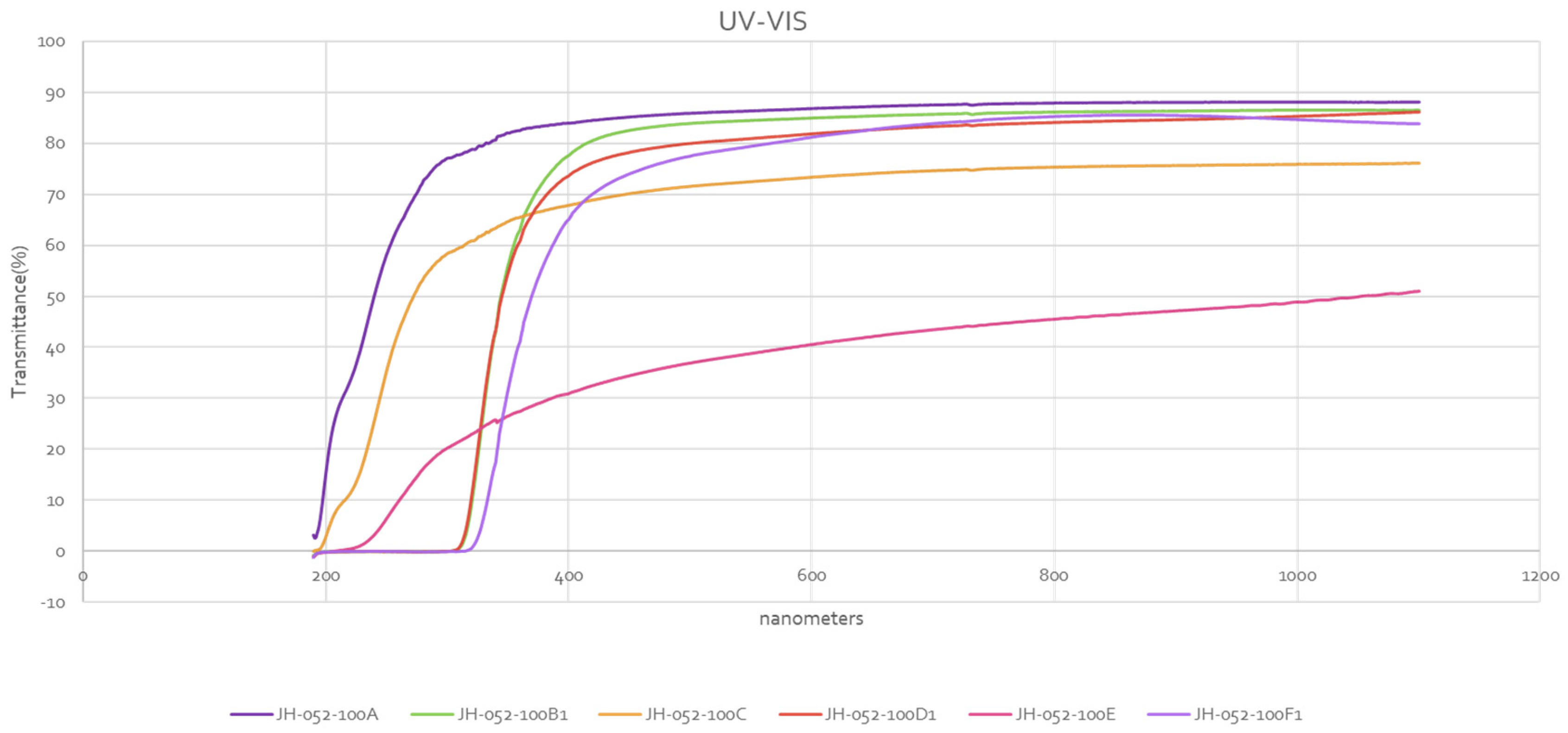
Figure 15 and Figure 16 present the UV-VIS and IR of polished Rafael substrates, some face-to-face glass bonded, and some stacked together with cellotape on the edges, respectively. In Figure 15, the single (-100A), the two substrates stacked together (-100C), and the four substrates stacked together (-100E) have no glass, and their transmittances start at UV at about 200 nm. The single substrate (-100B1) coated with glass (only one face coated) is compared with the single polished substrate (-100A). Comparison shows that coating one face with glass reduced the transmittance in the VIS; the reduction is very small but noticeable. Here, the glass coating was applied to a polished face, and the result was reduction of transmittance in the VIS. When coating was applied to the ground face of semi-polished spinel (Figure 5), the result was an increase in transmittance well above the theoretical value. The two substrates stacked together (-100C) are compared with two substrates face-to-face bonded with glass (-100D1), and (-100D1) has a larger transmittance in the VIS, while (-100C) has a lower transmittance because of four reflections. (-100D1) has a lower transmittance than the single substrate coated with glass (-100B1) in some of the VIS range, but its transmittance in the VIS is high. The four-stacked-together substrates (-100E) are compared with the four substrates that are face-to-face glass bonded (-100F1); transmittance of the glass-bonded substrates (100F1, thickness 3.2 cm, single substrate thickness is 0.8 cm) is much higher than (-100E) in the VIS. Transmittance of (-100F1) is comparable to the transmittance of two substrates glass bonded (-100D1); the glass-bonded substrates behave like a single substrate, i.e., two reflections.
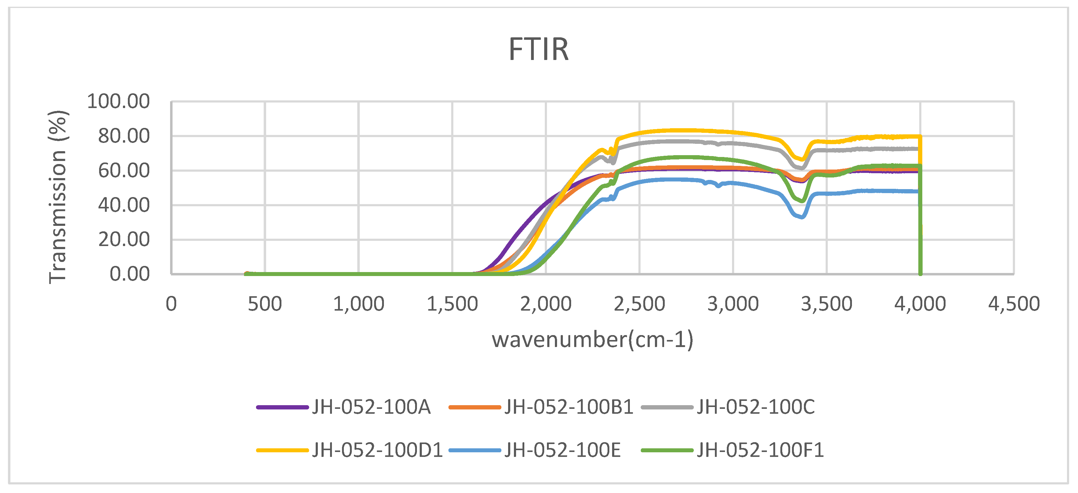
Figure 16 shows the IR spectra of the substrates of Figure 15. Comparison of the single polished substrate (-100A) with the single coated (only one face coated) substrate (-100B1) shows that they have similar, almost identical, transmittance in the 2400–4000 cm−1 range, and below 2350 cm−1 the transmittance of the polished uncoated (-100A) substrate is better than that of the one-face-coated polished spinel (-100B1). Comparison of the two polished stacks with cellotape on the edges (-100C) with the two polished, face-to-face glass-bonded substrates (-100D1) shows that -100D1 has better transmittance than -100C. Both show the absorbance at 3380 cm−1 (see also Figure 4 for polished substrates; all substrates have this band which is typical to Rafael spinels) and development of new faint band at 3560 cm−1. Comparison of the four polished substrates stacked with cello tape (-100E) with the four face-to-face glass-bonded substrates (-100F1) shows that -100F1 has better transmittance than -100E. As the number of substrates increases the cut-off (where total absorption starts), it shifts to a shorter wavelength.
4. Conclusions
A unique glass composition, which has a matched index of refraction and TCE tailored to be slightly lower than the TCE of spinel to put the glass coating under compression contains ingredients (MgO and Al2O3) to slow down the dissolution of spinel (MgAl2O4) into glass, is non-crystallizing in a broad temperature range and repeated firings, and has good chemical durability, was prepared and described.
Glass coating, when applied to the polished face of spinel, slightly reduced the transmittance relative to polished spinel.
Glass coating, when applied to semi-polished spinel (one face polished the second ground, coating applied to ground face) enhanced the transmittance above the theoretical value of spinel. This new phenomenon first reported here requires further studies to understand how and why the glass coating added a feature of anti-reflecting.
Face-to-face-bonded spinel substrates behave like a single substrate, i.e., have two reflections even for four substrates face-to-face bonded. A thick transparent spinel unit made from face-to-face-bonded substrates was demonstrated.
Funding
This research received no external funding.
Data Availability Statement
Data are contained within the article.
Acknowledgments
The author acknowledges Sofiya Kolusheva for optical measurements, Mariana Dov and Natalia Pears for technical assistance.
Conflicts of Interest
The authors declare no conflict of interest.
References
- Haggerty, J.S.; Rossetti, M. Development of Inexpensive Surface Finishing Process for Transparent Armor; Final Technical Report AD-769 938; Arthur D. Little, Inc.: Cambridge, MA, USA, 1973. [Google Scholar]
- Gentilman, R.L.; McGuire, P.T.; Fiore, D.; Ostreicher, K.; Askinazi, J. Low-cost sapphire windows. In Window and Dome Technologies VIII; SPIE: Bellingham, WA, USA, 2003; Volume 5078. [Google Scholar] [CrossRef]
- Machin, W.S.; Vest, R.W. Reactivity of Alumina Substrates with High Lead Glasses. In Processing of Crystalline Ceramics; Materials Science Research; Palmour, H., Davis, R.F., Hare, T.M., Eds.; Springer: Boston, MA, USA, 1978; Volume 11. [Google Scholar] [CrossRef]
- Prudenziati, M.; Mortem, B.; Cilloni, F.; Ruffi, G.; Saachi, M. Interactions between alumi-na and high lead glasses for hybrid componenrs. J. Appl. Phys. 1989, 65, 146–153. [Google Scholar] [CrossRef]
- Ganesh, I. A review on magnesium aluminate (MgAl2O4) spinel, synthesis, processing and applications. Int. Mater. Rev. 2013, 58, 63–112. [Google Scholar] [CrossRef]
- Rubat du Merac, M.; Kleebe, H.J.; Müller, M.M.; Reimanis, I.E. Fifty years of research and development coming to fruition, unraveling the complex interactions during processing of transparent magnesium aluminate (MgAl2O4) spinel. J. Am. Ceram. Soc. 2013, 96, 3341–3365. [Google Scholar] [CrossRef]
- Johnson, R.; Biswas, P.; Ramavath, P.; Kumar, R.S.; Padmanabham, G. Transparent polycrystalline ceramics: An overview. Trans. Indian. Ceram. Soc. 2012, 71, 73–85. [Google Scholar] [CrossRef]
- Shi, Z.; Zhao, Q.; Guo, B.; Ji, T.; Wang, H. A review on processing Polycrystalline magnesium aluminate spinel (MgAl2O4): Sintering techniques, material properties and machinability. Mater. Des. 2020, 193, 108858. [Google Scholar] [CrossRef]
- Wang, S.F.; Zhang, J.; Luo, D.W.; Gu, F.; Tang, D.Y.; Dong, Z.L.; Tan, G.E.B.; Que, W.X.; Zhang, T.S.; Li, S.; et al. Transparent ceramics: Processing, materials and applications. Prog. Solid State Chem. 2013, 41, 20–54. [Google Scholar] [CrossRef]
- Krell, A.; Klimke, J.; Hutzler, T. Advanced spinel and submicron Al2O3 for transparent armour applications. J. Eur. Ceram. Soc. 2009, 29, 275–281. [Google Scholar] [CrossRef]
- Patterson, M.C.L.; Caiazza, J.E.; Roy, D.W. Transparent spinel development. Proc. SPIE 2000, 4102, 59–68. [Google Scholar]
- Patterson, M.C.L.; Caiazza, J.E.; Roy, D.W. Fabrication of large thick panels of transparent spinel. Proc. SPIE 2001, 4452, 126–132. [Google Scholar]
- Jouini, A.; Yoshikawa, A.; Brenier, A.; Fukuda, T.; Boulon, G.A. Optical properties of transition metal ion-doped MgAl2O4 spinel for laser application. Phys. Status Solidi C 2007, 4, 1380–1383. [Google Scholar] [CrossRef]
- Goldstein, A.; Loiko, P.; Burshtein, Z.; Skoptsov, N.; Glazunov, I.; Galun, E.; Kuleshov, N.; Yumashev, K. Development of saturable absorbers for laser passive Q-switching near 1.5 mm based on transparent ceramic Co2+:MgAl2O4. J. Am. Ceram. Soc. 2016, 99, 1324–1331. [Google Scholar] [CrossRef]
- Luo, W.; Ma, P.; Xie, T.; Dai, J.; Pan, Y.; Kou, H.; Li, J. Fabrication and spectroscopic prop-erties of Co:MgAl2O4 transparent ceramics by the HIP post-treatment. Opt. Mater. 2017, 69, 152–157. [Google Scholar] [CrossRef]
- Liu, Q.; Su, S.; Hu, Z.; Chen, X.; Xie, T.; Yang, Z.; Pan, H.; Liu, X.; Li, J. Fabrication and properties of Co:MgAl2O4 transparent ceramics for saturable absorber from co-precipitated na-nopowder. J. Am. Ceram. Soc. 2019, 102, 3097–3102. [Google Scholar] [CrossRef]
- Song, E.H.; Zhou, Y.Y.; Wei, Y.; Han, X.X.; Tao, Z.R.; Qiu, R.L.; Xia, Z.G.; Zhang, Q.Y. Thermally stable narrow-band green-emitting phosphor MgAl2O4:Mn2+ toward Wide Color Gamut Backlight Display Application. J. Mater. Chem. C 2019, 7, 8192–8198. [Google Scholar] [CrossRef]
- Rimpongpisarn, T.; Wattanathana, W.; Sukthavorn, K.; Nootsuwan, N.; Hanlumyuang, Y.; Veranitisagul, C.; Laobuthee, A. Novel luminescent PLA/MgAl2O4:Sm3+ composite filaments for 3D printing application. Mater. Lett. 2018, 237, 270–273. [Google Scholar] [CrossRef]
- Chen, C.F.; Doty, F.P.; Houk, R.J.T.; Loutfy, R.O.; Volz, H.M.; Yang, P. Characterizations of a hot-pressed polycrystalline spi-nel:Ce scintillator. J. Am. Ceram. Soc. 2010, 93, 2399–2402. [Google Scholar] [CrossRef]
- Swab, J.J.; Pavlacka, R.; Gilde, G.; Kilczewski, S.; Wright, J.; Harris, D. Determining the Strength of Coarse-Grained AlON and Spinel. J. Am. Ceram. Soc. 2013, 97, 592–600. [Google Scholar] [CrossRef]
- Kilczewski, S.M.; Wright, J.C.; Pavlacka, R.J.; Swab, J.J.; Adams, J.W. Flexure Strength and Optical Transparency of Magnesium–Aluminate Spinel (MgAlO4): Influence of Polishing and Glass Coating; Report ARL-TR-7900; US Army Research Laboratory: Adelphi, MD, USA, 2016. [Google Scholar]
- Hormadaly, J. Empirical methods for estimating the linear coefficient of expansion of oxide glasses from their composition. J. Non-Cryst. Solids 1986, 79, 311–324. [Google Scholar] [CrossRef]
- Liu, X.; Han, D.; Mao, X.; Zhang, J.; Ren, H.; Lin, H.; Wang, S. Joining transparent spinel ceramics using refractive index–matched glass. J. Eur. Ceram. Soc. 2022, 42, 3579–3585. [Google Scholar] [CrossRef]
- Hormadaly, J. Glass Composition for Coating and Bonding of Polycrystalline Spinel (Transparent Ceramic) Substrates. WO 2023/026276 A1, 2 March 2023. [Google Scholar]
Figure 1.
Heating profile I.

Figure 2.
Heating profile II.

Figure 3.
UV-VIS transmittances of polished spinel substrates (Rafael).

Figure 4.
IR transmittances of polished spinel substrates (Rafael).

Figure 5.
Transmittance of Rafael spinel semi-polished (one face polished, second face ground, coated with glass paste on ground face and fired).
Figure 5.
Transmittance of Rafael spinel semi-polished (one face polished, second face ground, coated with glass paste on ground face and fired).

Figure 6.
Comparison of transmittances of polished (JH-052-33A) and glass-coated spinel (JH-052-31A) in the UV-VIS semi-polished.
Figure 6.
Comparison of transmittances of polished (JH-052-33A) and glass-coated spinel (JH-052-31A) in the UV-VIS semi-polished.

Figure 7.
Comparison of transmittances of polished (JH-052-33A) and glass-coated semi-polished spinel (JH-052-31A) in the IR.
Figure 7.
Comparison of transmittances of polished (JH-052-33A) and glass-coated semi-polished spinel (JH-052-31A) in the IR.

Figure 8.
UV-Vis of polished substrates JH-051-86A-C (Ceramtech).

Figure 9.
FTIR of polished substrates JH-051-86A-C (Ceramtech).

Figure 10.
Comparison between two Rafael glass-bonded spinels (-36) and two stacked polished spinels (-33B).
Figure 10.
Comparison between two Rafael glass-bonded spinels (-36) and two stacked polished spinels (-33B).

Figure 11.
Comparison between two Rafael glass-bonded spinels (-36) and two polished spinels (-33B).
Figure 11.
Comparison between two Rafael glass-bonded spinels (-36) and two polished spinels (-33B).

Figure 12.
Comparison among polished single, two substrates taped together and two substrates bonded by a glass (Rafael).
Figure 12.
Comparison among polished single, two substrates taped together and two substrates bonded by a glass (Rafael).

Figure 13.
Polished substrates (Ceramtec) edge bonded with glass.

Figure 14.
Two polished spinel structures (Ceramtec) edge bonded with glass.

Figure 15.
Comparison among transmittances (UV and VIS) of polished substrates, single with no coating, single with coating (one face coated with glass), two stacked together with tape, two bonded with glass, four stacked together with tape, and four substrates face-to-face bonded with glass.
Figure 15.
Comparison among transmittances (UV and VIS) of polished substrates, single with no coating, single with coating (one face coated with glass), two stacked together with tape, two bonded with glass, four stacked together with tape, and four substrates face-to-face bonded with glass.

Figure 16.
Comparison among transmittances (FTIR) of polished substrates, single with no coating, single with one face coated with glass, two stacked together with tape, two face-to-face bonded with glass, four stacked together with tape, and four substrates face-to-face bonded with three layers of glass.


Table 1.
Glass composition.
| Ingredient | Mole Percent | Weight Percent (wt.%) |
|---|---|---|
| PbO | 25.83 | 54.89 |
| MgO | 5.98 | 2.3 |
| ZnO | 5.98 | 4.63 |
| Al2O3 | 5.98 | 5.81 |
| SiO2 | 55.08 | 31.51 |
| TiO2 | 1.13 | 0.86 |
Table 2.
Properties of glass compositions of batches 1, 2, 3, and 4.
| Glass Code | Tg (°C) | Td (°C) | CTE 100–300°C (10−6/°C) | Nd |
|---|---|---|---|---|
| Batch 1 | 568 | 605 | 7.02 | 1.727 |
| Batch 2 | 553 | 602 | 6.1 | 1.727 |
| Batch 3 | 565 | 606 | 5.89 | 1.719 |
| Batch 4 | 564 | 610 | 6 | 1.728 |
Table 3.
Glass compositions of the system La2O3-MgO-ZnO-Al2O3-B2O3-SiO2.
| Mole Percent | |||
|---|---|---|---|
| Ingredient | I | II | III |
| La2O3 | 17.75 | 22.00 | 24.00 |
| MgO | 6.00 | 6.00 | 6.00 |
| ZnO | 12.00 | 12.00 | 12.00 |
| Al2O3 | 12.25 | 14.00 | 12.00 |
| B2O3 | 15.00 | 11.00 | 15.00 |
| SiO2 | 37.00 | 35.00 | 31.00 |
Table 4.
Properties of glasses of the system La2O3-MgO-ZnO-Al2O3-B2O3-SiO2.
| Sample | Tg °C | Td °C | TCE100–300°C (10−6) | Nd |
|---|---|---|---|---|
| I | 688 | 726 | 7.2 | 1.717 |
| II | - | - | 7.6 | 1.748 |
| III | 702 | 745 | 8.2 | 1.774 |
Disclaimer/Publisher’s Note: The statements, opinions and data contained in all publications are solely those of the individual author(s) and contributor(s) and not of MDPI and/or the editor(s). MDPI and/or the editor(s) disclaim responsibility for any injury to people or property resulting from any ideas, methods, instructions or products referred to in the content. |
© 2024 by the author. Licensee MDPI, Basel, Switzerland. This article is an open access article distributed under the terms and conditions of the Creative Commons Attribution (CC BY) license (https://creativecommons.org/licenses/by/4.0/).
Share and Cite
MDPI and ACS Style
Hormadaly, J. Glass Composition for Coating and Bonding of Polycrystalline Spinel Ceramic Substrates. Ceramics 2024, 7, 101-114. https://doi.org/10.3390/ceramics7010008
AMA Style
Hormadaly J. Glass Composition for Coating and Bonding of Polycrystalline Spinel Ceramic Substrates. Ceramics. 2024; 7(1):101-114. https://doi.org/10.3390/ceramics7010008
Chicago/Turabian StyleHormadaly, Jacob. 2024. "Glass Composition for Coating and Bonding of Polycrystalline Spinel Ceramic Substrates" Ceramics 7, no. 1: 101-114. https://doi.org/10.3390/ceramics7010008