Abstract
The use of Stirling-cycle-based heat pumps in high-temperature applications and waste heat recovery at an industrial scale is of increasing interest due to the promising role in producing thermal energy with zero CO2 emissions. This paper analyzes one such technology as developed by Olvondo Technology and installed at the pharmaceutical company AstraZeneca in Sweden. In this application, the heat pump used roughly equal amounts of waste heat and electricity and generated 500 kW of steam at 10 bar. To develop and widen the use of a high-performance high-temperature heat pump that is both economically and environmentally viable and attractive, various analysis tools such as exergy analysis and life cycle assessment (LCA) can be combined. The total cumulative exergy loss (TCExL) method used in this study determines total exergy losses caused throughout the life cycle of the heat pump. Moreover, an LCA study using SimaPro was conducted, which provides insight into the different emissions and the overall environmental footprint resulting from the construction, operation (for example, 1, 8, and 15 years), and decommissioning phases of the heat pump. The combined results were compared with those of a fossil fuel oil boiler (OB), a bio-oil boiler (BOB), a natural gas-fired boiler (NGB), and a biogas boiler (BGB).
1. Introduction
The need for sustainable energy solutions has never been more important than today [1]. Our current energy infrastructure and use patterns are unsustainable. The change in the climate we face today is most likely largely because of emissions of greenhouse gases (GHGs). Fossil fuel combustion in the energy (heat, fuel, and electricity) industry is responsible for about two-thirds of global emissions of GHGS, primarily CO2 emissions. The still increasing use of fossil fuels has an impact not only on the environment, but also on human wellbeing. Changes should be introduced in the energy market to alleviate the climate crisis. To do so, it is essential to move towards sustainable technologies that supply energy carriers where and when needed, causing minimal environmental damage. There has been a transition going on for decades, but this also needs to go even further and faster too.
Today, heating accounts for almost half the total consumption of heat, power, and fuels in Europe [2]. Oil-, gas-, and coal-fired boilers make up a large part of industrial energy use and are the primary components of power generation and industrial process plants. An estimated 5.6% of the compound annual growth rate (CAGR) in the global oil and gas industry is found in the United States, Canada, Japan, China, and Europe [3]. The European Environment Agency (EEA) reported that the United States boiler population consists of around 43,000 units with a gross input capability of 439 GW. This is concentrated in five sectors (i.e., plastics, paper, food, processing, and metals), comprising 82% of the overall boiler capacity. In regional market clusters, China will remain among the fastest growing. The Asia-Pacific demand is expected to exceed 132.8 thousand tons of steam per hour (TSPH) by 2027 [3]. The global demand for industrial boilers, estimated at 859.8 TSPH in 2020, is expected to reach a size of 1.2 million TSPH by 2027, revised after the COVID-19 pandemic, rising with a CAGR of 4.7% over the 2020–2027 analysis period [3].
A heat pump adds mechanical energy to a system that transfers heat from lower temperatures to higher temperatures [4]. The mechanism can in theory be described by an inverse Carnot cycle or refrigeration cycle, noting that most heat pumps operate using a vapor-compression process that is in fact a reversed Rankine cycle.
In 2020, European heat pump sales increased by 7.4%. With a life expectancy of about 20 years, the present European heat pump stock totals 14.86 million units [5]. The European Heat Pump Association endorses the use of heat pumps in industrial processes, complementing district heating and helping to stabilize the electricity grid [4].
Despite the COVID-19 pandemic, heat pump sales continued to rise. Sweden showed a steady increase in use of heat pumps over the years. The total number of heat pumps sold grew by about 555,200 from 2013 to 2019. Only in 2019, 40 million heat pumps were in use across the EU-27 and the United Kingdom (UK), of which Sweden has a share of roughly 1.9 million heat pumps [6].
Heat pumps in Finland generate approximately 12 TWh of clean, non-combustive heating and refrigeration energy per year. In 2020, 102,000 heat pumps were sold, an increase of 4% compared to that in the year before, bringing the total amount of heat pumps installed well over one million according to the estimates from the Finnish Heat Pump Association [7].
1.1. Current Market Developments of Stirling-Cycle-Based Heat Pumps (SC HPs)
The second highest market in Europe for process heating is the industry sector. The industrial process heating demand is high in countries such as Sweden, Finland, the UK, Estonia, France, and Germany [8]. It was reported that 27% of the process heat demand in European countries is for the temperature range 100–200 °C [8]. The majority of process heating demand, however, is for higher temperatures.
The SC HP technology [9,10] can help minimize energy use and increase the use of renewable energy aimed to achieve the global climate objectives.
The assessment of the European market for high-temperature heat pumps reveals a large market potential in the EU27 + 4 of more than 57,000 of these technology units, based on the likely assumption that 65% of the industries that have a demand for process heat also have sufficient amounts of excess waste heat. This technology can potentially transform a large part of the existing potential of 175 TWh excess waste heat into industrial-process heat to cover an estimated 47 TWh demand in the 100–200 °C output temperature range [8].
1.2. Life Cycle Assessment (LCA)
The concept of sustainability has developed over the past couple of years after many global deliberations. The principle of sustainability stresses on merging the social, economic, and environmental interests. LCA presents a tremendous promise of enhancing environmental sustainability and advancing new technologies, and it has historically been used for the quantification and retrospective appraisal of commercially advanced technology. However, the application of LCA to new technologies at research and development levels poses many methodological problems [11].
For the study reported here, the LCA approach was employed using the SimaPro 8.3.3 software. SimaPro is a software tool that records and evaluates the sustainable performance of many goods or processes [12]. For each phase of the life cycle, i.e., manufacturing, operation, and decommissioning, inventory data sets were collected and combined with the data from the ecoinvent (v. 3.5) database [13]. The exergy analysis and environmental impacts calculations were made for each phase.
1.3. Exergy Analysis
Exergy is the potential upper limit of the work rate that an energy source system can have if the inputs are brought into equilibrium with a reference environment, which in short means the capacity of the energy to do work. Especially for planning, refining, upgrading, and controlling energy conversion processes, exergy analysis is useful. An exergy analysis can locate and calculate the sums of the system’s thermodynamic losses. The degradation of exergy is strictly proportional to entropy production via the simple linear relation: exergy consumption (J or W) = temperature of the surroundings (K) × entropy production (J/K or W/K) [14].
The total cumulative exergy loss (TCExL) method has been developed [15] for the assessment of technological systems. It includes all exergy losses incurred during a system’s life and operation phase. The advantage of the TCExL method is that it is based on exergy losses which are thermodynamically very well defined. TCExL is calculated by combining the loss of internal exergy and exergy losses due to abatement and due to land use as given in the following equation [15]:
where the internal exergy loss of a process or system is calculated as given in the following equations [15]:
where Exinput equals the cumulative exergy demand (CExD) as is calculated by the SimaPro software and is readily obtained from the results; abatement exergy loss is the loss of exergy due to processes that reduce waste and emissions from the technical system:
and an exergy loss can also be allocated to the use of land and can be written as:
TCExL = Exloss,internal + Exloss,abatement + Exloss,land,
Exloss,internal = Exinput − Exproduct − Exemissions&wasteflow,
Exloss,abatement = ∑ (emissioni × Exloss,i),
Exloss,land = Land use × 215 GJ/(ha × yr).
For the research work presented here, only the abatement exergy values of CO2, SO2, NOX, and phosphates have been considered [15]. Exergy losses of 215 GJ per hectare per year were calculated with Net Primary Production (NPP) values [15,16].
1.4. Environmental Impact Assessment (EIA)
The UNEP describes EIA as a tool to recognize and quantify the environmental effects of a project [17]. It is targeted at predicting early environmental effects during the preparation and construction of projects. Both environmental and economic gains, such as decreased cost, project time and design expenses, avoided treatment/clean-up costs, and consequences of laws and regulations can be evaluated using EIA [17]. The EIA is part of an LCA.
For this study, the environmental impacts were calculated using the SimaPro software. The Eco-Indicator 99 [18] framework discloses the environmental impacts in terms of numbers or scores. The key categories included in this analysis were climate change, respiratory effects, ozone layer depletion, and acidification [18]. These categories were chosen, because they offer an overview of key consequences on human health and the environment.
2. Materials and Methods
The heating systems studied in this study were an SC HP, a fossil fuel oil-based boiler (OB), a bio-oil boiler (BOB), a natural-gas-fired boiler (NGB), and a biogas boiler (BGB). These five systems were assessed for locations in Sweden under equivalent climate conditions. The location was chosen based on where SC HPs under study in the EU Horizon 2020 project HighLift [9] are located, which is in Gothenburg (Sweden). Depending on the location selected, the analysis results may differ. It was assumed that the same boiler could be used for all four fuels.
2.1. Case Study
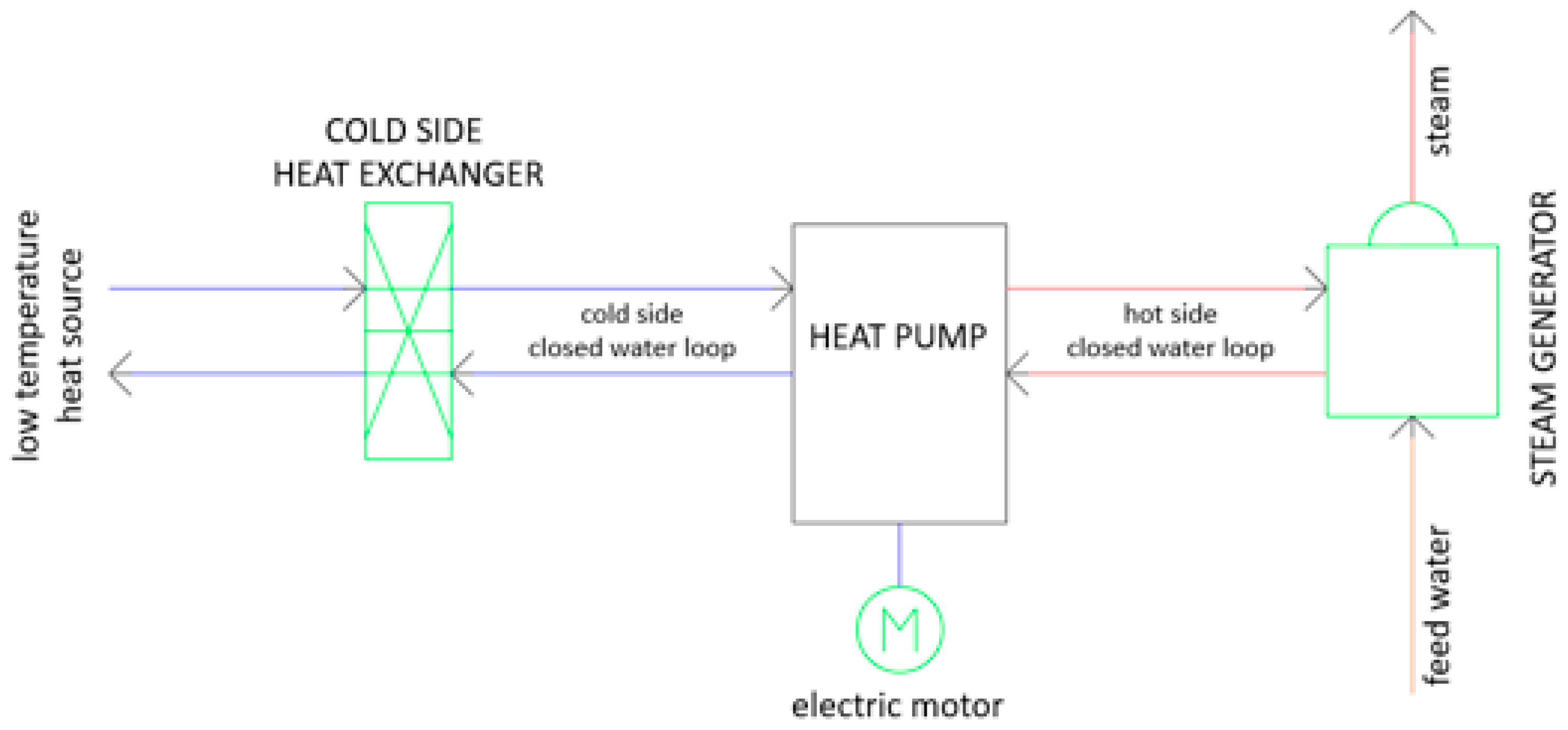
The SC HP under study comprised a heater, a regenerator, a cooler, and expansion and compression cylinders. The internal heat exchangers included a heating section, a regenerating section, and a cooling section, with all integrated into the same unit. The heat pump as shown as a simplified flowsheet in Figure 1 generated a high-pressure (i.e., 10 bar) steam with an output of 450 to 500 kW using waste heat and electrical energy input [9].
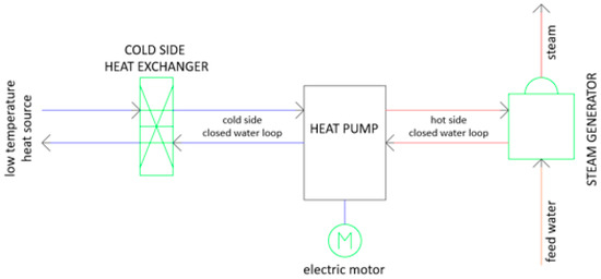
Figure 1.
Simplified flowsheet of the heat pump installation [9].
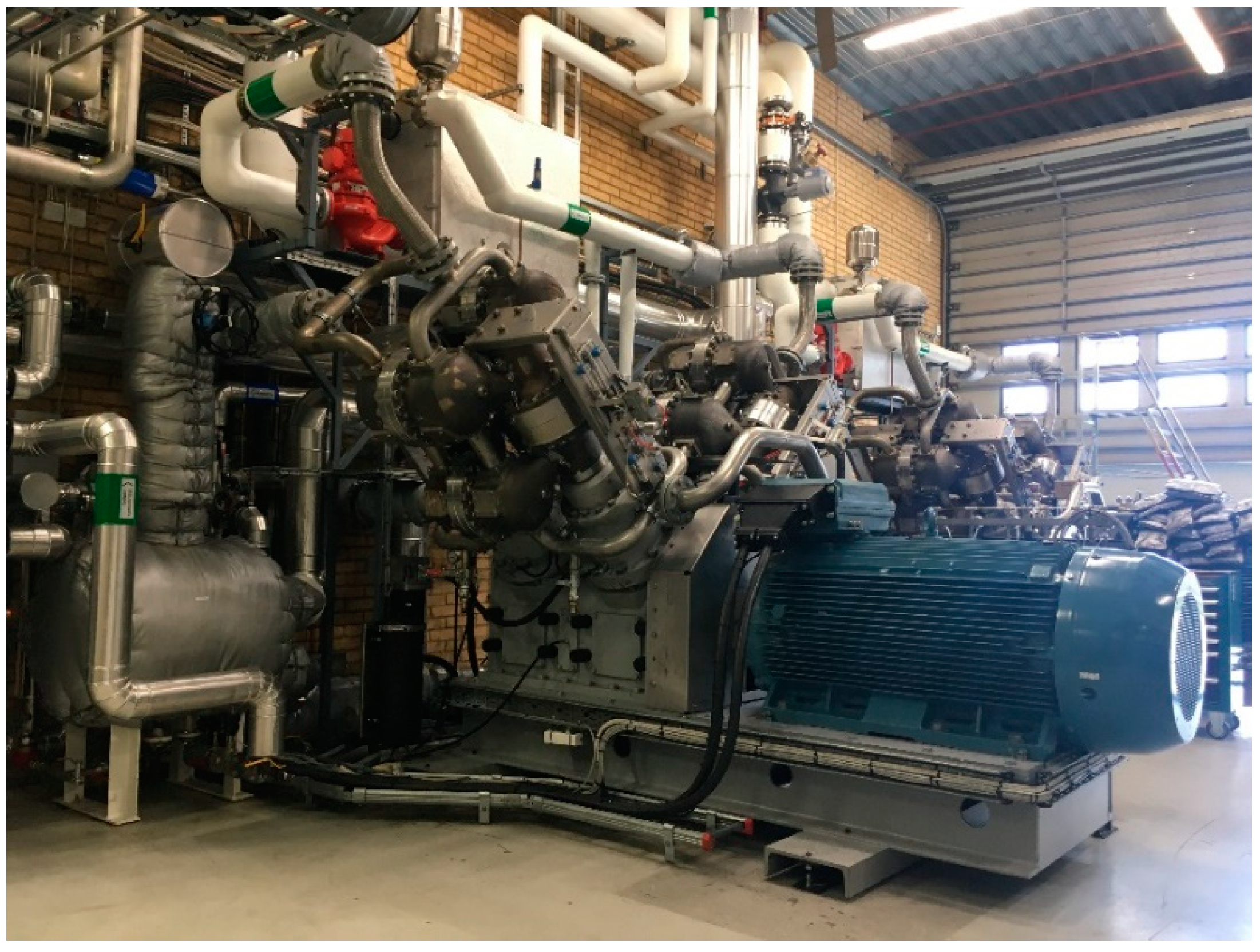
The heat pump used closed water loops to transfer energy to and from the heat pump. The cold energy was transferred to the cold-side closed water circuit in a plate heat exchanger, while the hot-side closed water loop was heating and evaporating feed water in a steam generator. Figure 2 gives a photo of the heat pump.
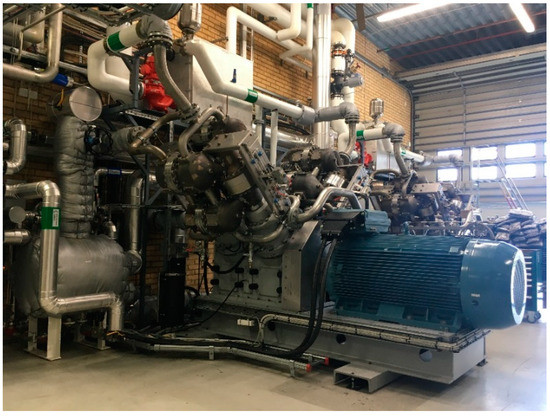
Figure 2.
The highlift Stirling-cycle-based heat pump (SC HP) developed by Olvondo Technology, Norway and being used by the pharmaceutical company AstraZeneca, Gothenburg, Sweden.
This corresponded to a heat pump coefficient of performnce COPh of 2, which was a rounded-up approximation of the actual COPh. With the new 750 kW heat pump that is currently taken into use, a COPh in the range of 1.7–1.9 can be expected for these temperatures. More information about the actual equipment performance was reported by the authors recently [19].
2.2. System Boundary
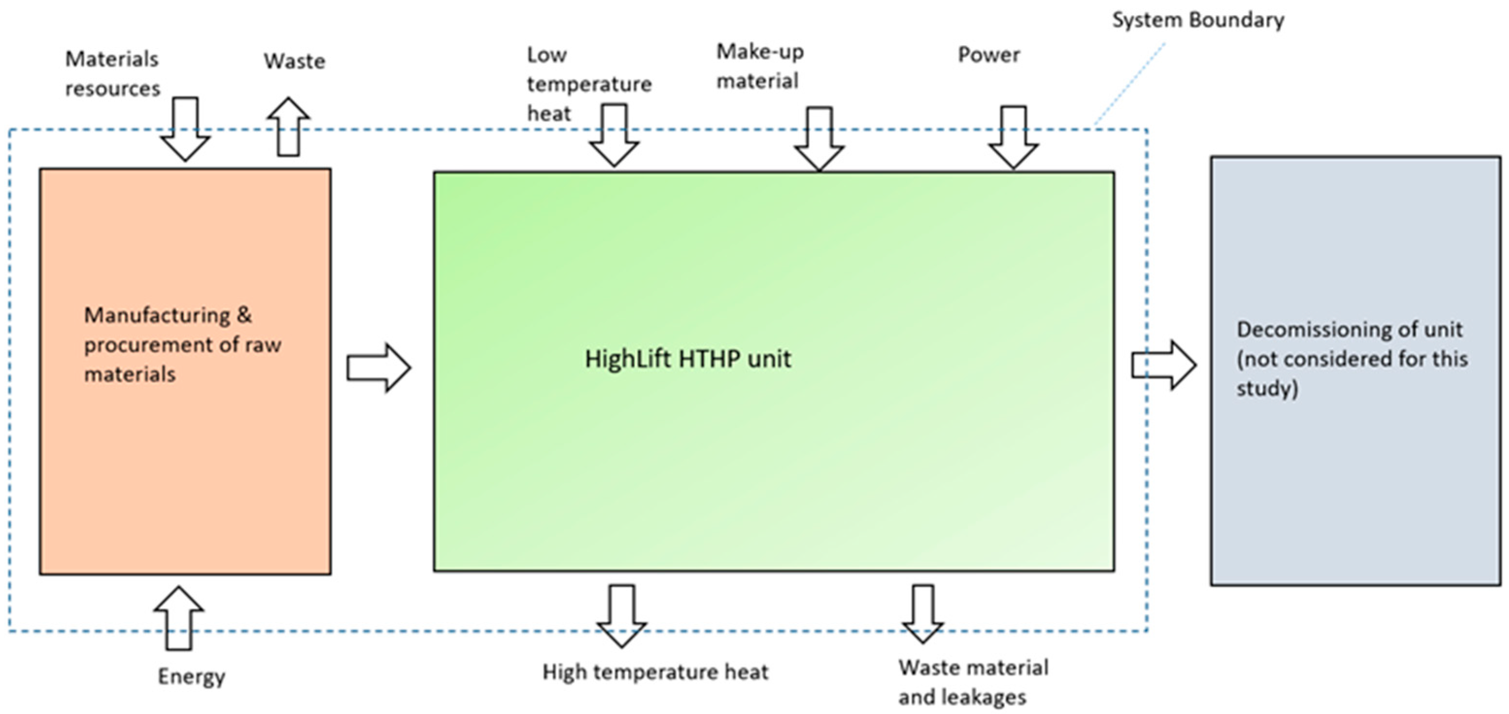
Before evaluating the system, it is necessary to determine the system boundaries for it. Figure 3 shows the system boundary for the SC HP. Manufacturing included the acquisition and production of raw materials and construction activities for the unit assembly. The end-of-life fate of the heat pump after the lifetime was also assessed. The decommissioning phase included the final disassembling of the unit and the disposing/recycling of waste.
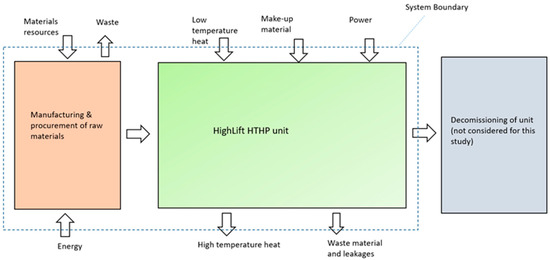
Figure 3.
Graphic representation of the system boundary for the life cycle assessment of the SC HP [20].
The construction phase (a), plus operation phases for 1 year (b), 8 years (c), or 15 years followed by decommissioning (d) and also the decommissioning phase alone with no use phase (e) were considered. The reason for considering the 1- and 8-year operating phases was to assess the impacts connected with each year as well as when the unit’s (expected) half life span elapsed. Decommissioning was only considered after 15 years of operation, since the life spans of all the five heating technologies compared in this paper were assumed to be 15 years [19].
The system boundary of the systems containing a natural/biogas- or fossil/bio-oil-fired boiler included the extraction/acquisition of raw materials as well as the fuel and materials delivery.
3. Results
The section discusses and compares the total cumulative exergy losses, environmental impacts associated with the SC HP, the fossil fuel OB, the BOB, the NGB, and the BGB designed for the 500 kW heat output capacity. For the fuel-fired boilers, a 500 kW LHV (lower heating value) fuel input is needed; for the SC HP, 250 kW low-temperature heat plus 250 kW electricity are needed to generate 500 kW of high-temperature heat—see also [19].
3.1. Exergy Analysis
The overall thermodynamic performances of the boilers were evaluated based on their exergy losses. The results of the TCExL calculations are collected in Table 1.

Table 1.
Summary of results of the total cumulative exergy loss (TCExL) calculations for the phases construction + 1-year operation, construction + 8-year operation, and construction + 15-year operation + decommissioning.
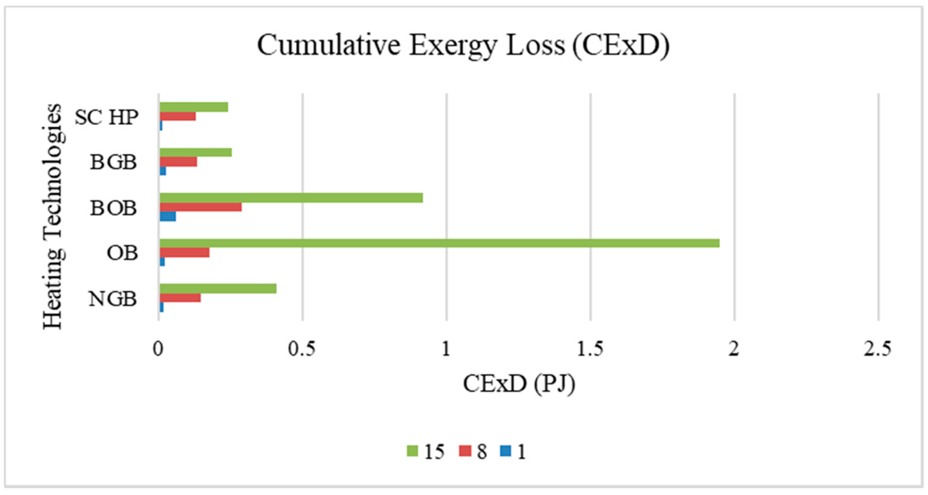
Figure 4 shows the comparison of the CExDs of the different technologies. From the results, it can be seen that the OB gave the highest CExD followed by the BOB, the NGB, and finally the BGB. It should be noted that the CExD included material (minerals, metals, and water) resources as well as energy resources. The large contribution of exergy demand was associated with fuel production and its use for heating. The combustion contributed the most significant amount of exergy destruction. The transport of biogas is highly energy-demanding.
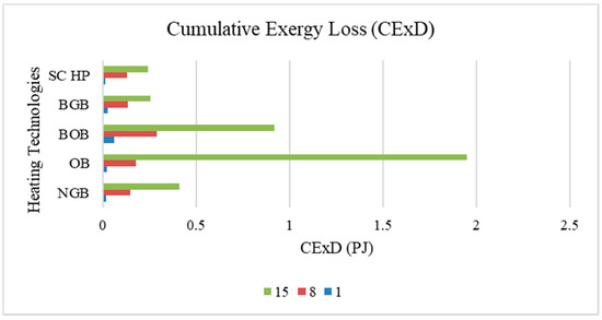
Figure 4.
CExDs of different heating technologies for the phases construction + 1-year operation (1), construction + 8-year operation (8), and construction + 15-year operation + decommissioning (15).
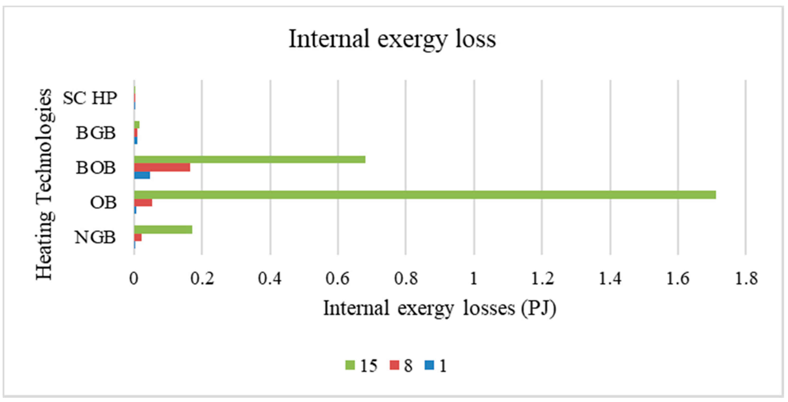
For the OB and the BOB, the internal exergy losses were comparatively high for 8 and 15 years of operation, as shown in Figure 5. The source of input for bio-oil was wood from Sweden, and the impact associated with the land to grow that wood was included for exergy loss calculations.
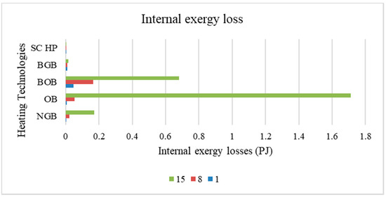
Figure 5.
Internal exergy losses for different heating technologies for the phases construction + 1-year operation (1), construction + 8-year operation (8), and construction + 15-year operation + decommissioning (15).
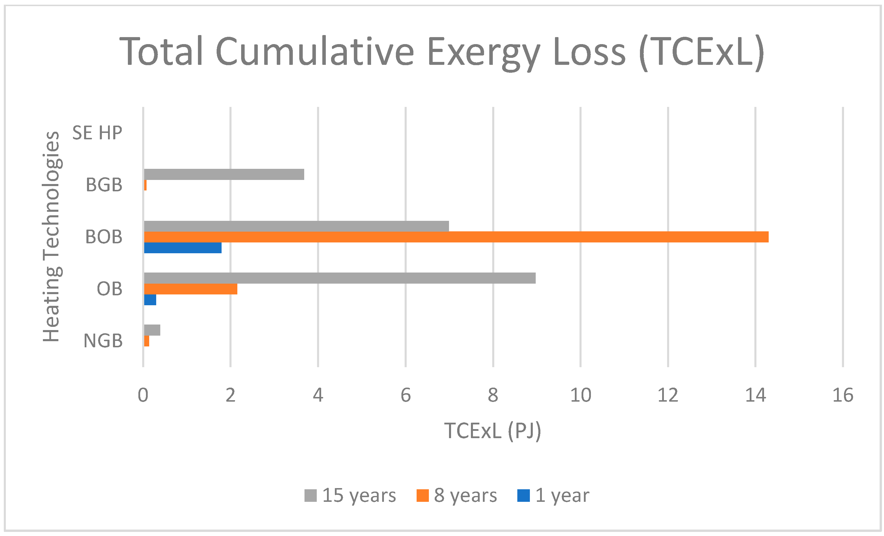
A low TCExL was calculated for the SC HP, as can be seen in Figure 6. This is the result of lower emissions and thus lower abatement exergy losses. The higher TCExLs for the NGB and the OB came from the contribution of the life cycle footprint of natural gas and oil, i.e., extraction, processing, distribution, and combustion. If the biofuel cannot be sourced locally, economic and environmental impacts may be higher than for natural gas due to transportation costs.
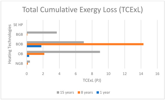
Figure 6.
TCExLs of different heating technologies for construction phase + 1-year operation phase (1), construction phase + 8-year operation phase (8), and construction phase + 15-year operation phase + decommissioning phase (15).
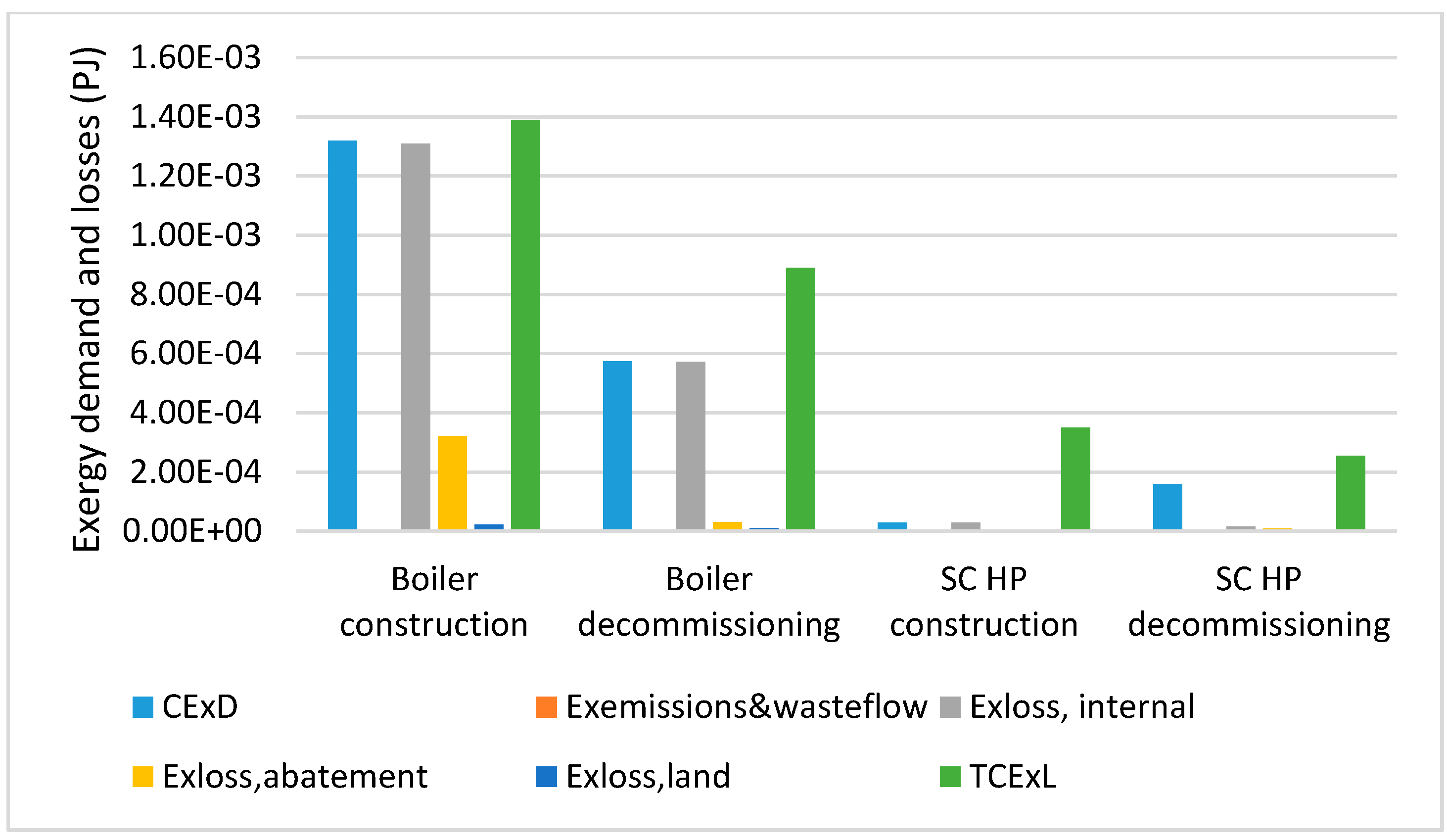
For further analysis, only the construction and decommissioning of the SC HP and the boilers were considered. Table 2 shows that for the SC HP most of the impact stemmed from the construction of the unit with only minor contributions from the operation phase of the SC HP.

Table 2.
Summary of the results of the TCExL calculations for the construction and decommissioning of the boilers and the construction and decommissioning of the SC HP.
The values in the table for decommissioning included the fact more pure (recovered) materials were obtained compared to the materials entering the construction phase (incl. metal ores).
Figure 7 shows the relative cumulative exergy demands and losses associated with the manufacturing and decommissioning of the boilers and the heat pump. It can be seen from the results that the TCExL of the manufacturing phase was lower for the heat pump than for the boilers. The values for exergy demand and losses during decommissioning of the boilers and the HP unit were caused by the 90% recycling of materials.
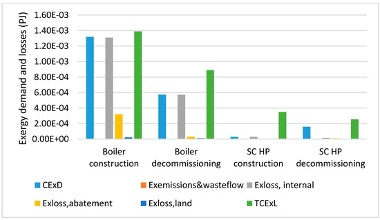
Figure 7.
Exergy demands and losses for the construction and decommissioning of the boilers and the heat pump. Unit: PJ.
3.2. Environmental Analysis
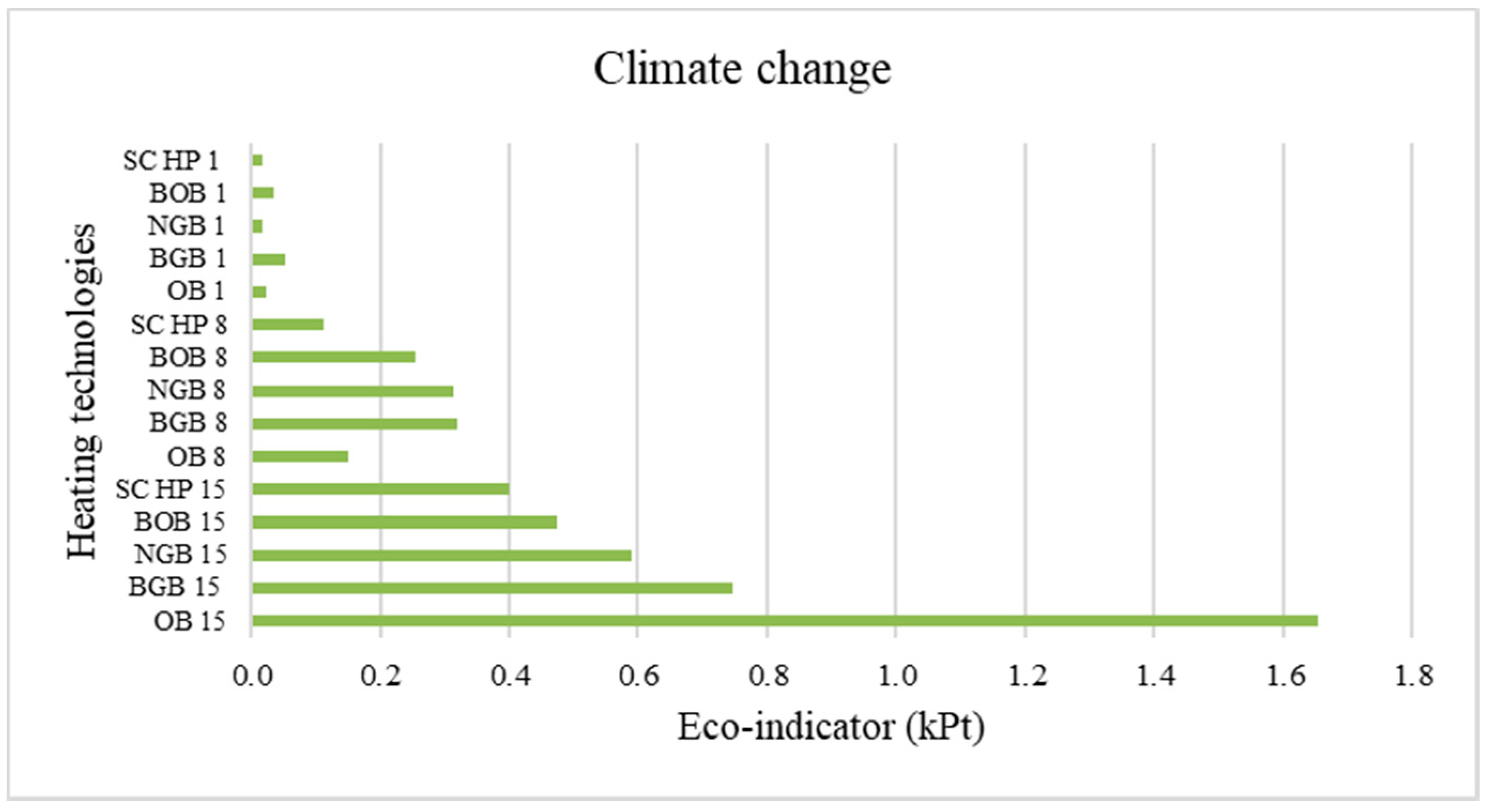
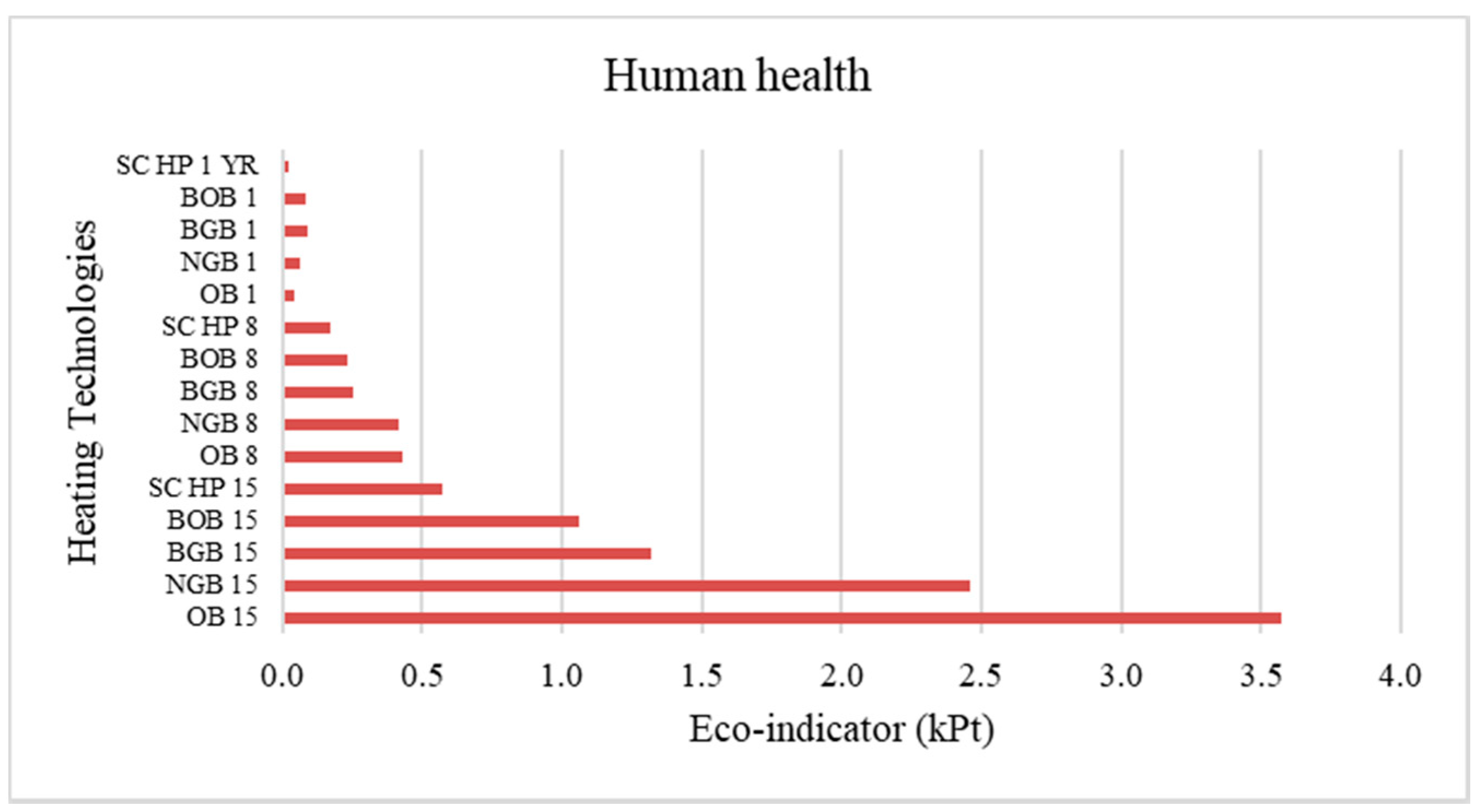
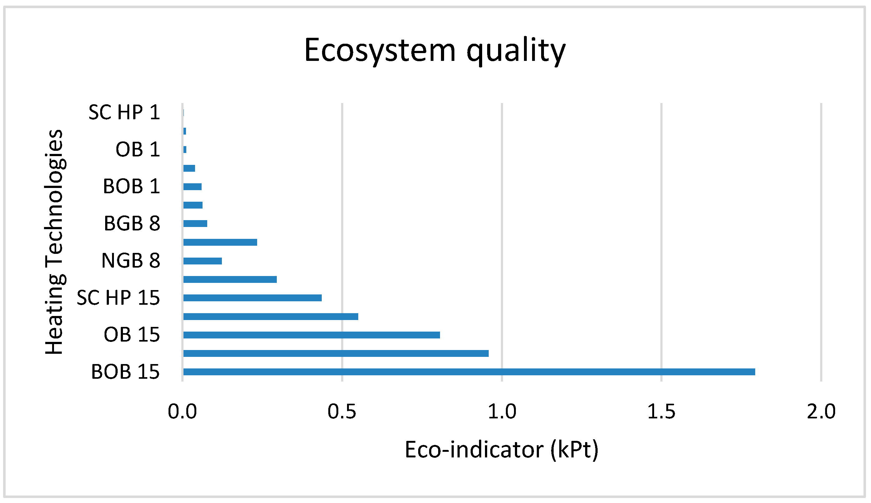
The next figures shows the environmental effects linked with all the heating technologies (NGB, OB, BGB, and BOB) designed for a capacity of 500 kW and the impacts measured against the SC HP technology. To evaluate the impact categories climate change, ecosystem, and human health, the Eco-Indicator 99 method was employed in the study as shown in Figure 8, Figure 9 and Figure 10, respectively. The values are given with kPt as the unit. Figure 8 indicates that fossil fuel systems had a three-to-five times higher negative effect on the environment than the SC HP, which is in line with the IMPACT 2002+ assessment technique.
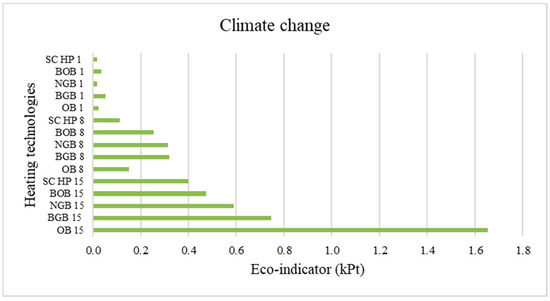
Figure 8.
Characterization of damage via climate change for construction + 1-year use (1), construction + 8-year use (8), and construction + 15-year use + decommissioning (15).
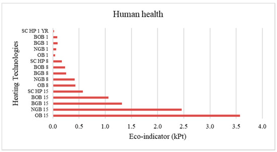
Figure 9.
Characterization of damage on human health for construction + 1-year use (1), construction + 8-year use (8), and construction + 15-year use + decommissioning (15).
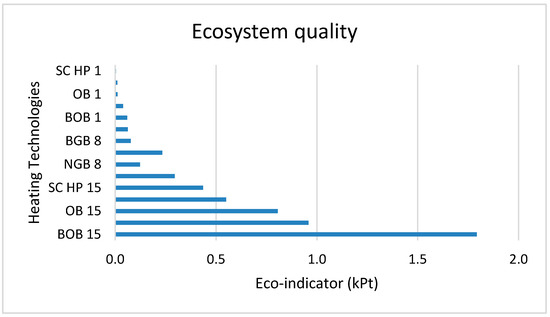
Figure 10.
Characterization of damage on ecosystem quality for construction + 1-year use (1), construction + 8-year use (8), and construction + 15-year use + decommissioning (15).
Biogas plays a major role in reducing emissions of GHGs. However, unwanted emissions of methane and nitrous oxides (N2O) must be taken into account. Of all the gaseous emissions considered for direct emission from biogas combustion, the nitrogen oxides (NOx) are of most interest. The NOx pollution problem includes ozone synthesis, which is a harmful compound. One of the main issues is the ozone at the ground level (smog), which arises due to NOx and volatile organic compounds (VOCs) reacting under sunlight. This occurrence is detrimental to humans, animals, and plants. Methane losses at the biogas processing plant and natural-gas-fired heat generation add to the global warming potential.
It can be seen from Figure 9 how fossil fuel boilers had a higher negative effect on human health compared to the SC HP. This is because of the air emissions and toxicity associated with the fuel combustion.
Figure 10 shows the effects of heating technologies towards the ecosystem quality. It can be seen from the figure that the BOB had more impact on the ecosystem quality. A quite important consideration is the amount of area necessary for the wood from which bio-oil is made. The use of land is known to have the highest environmental effects of this fuel.
Transportation, combustion, gas, and sawdust by-products give significant contributions (all of them releasing NOx emissions). The CO2 emissions from natural gas combustion quantify the significant effect of the boiler use on climate change. Methane emissions occur mainly because of losses in long-distance pipelines while transporting natural gas. The emissions of chromium (VI) from iron manufacture are toxic for humans and may cause cancer. Nitrogen oxides result in photochemical ozone production, acidification, and terrestrial and aquatic eutrophication as a result of the combustion phase.
An analysis of the footprint of an OB’s life cycle indicated that the overall effect was similar to that of natural gas. For the OB, copper and zinc pollutants affected the atmosphere and hence air quality, again primarily via combustion. The switch to renewable (biomass-based) fuel had a greater influence on natural gas systems than for the fossil fuel OB. Oil-based heating systems with environmental impacts between three and four times greater than for the SC HP are the most environmentally unfriendly option. There are significant variations between biofuel and fossil fuel systems in the emission into air and energy supply.
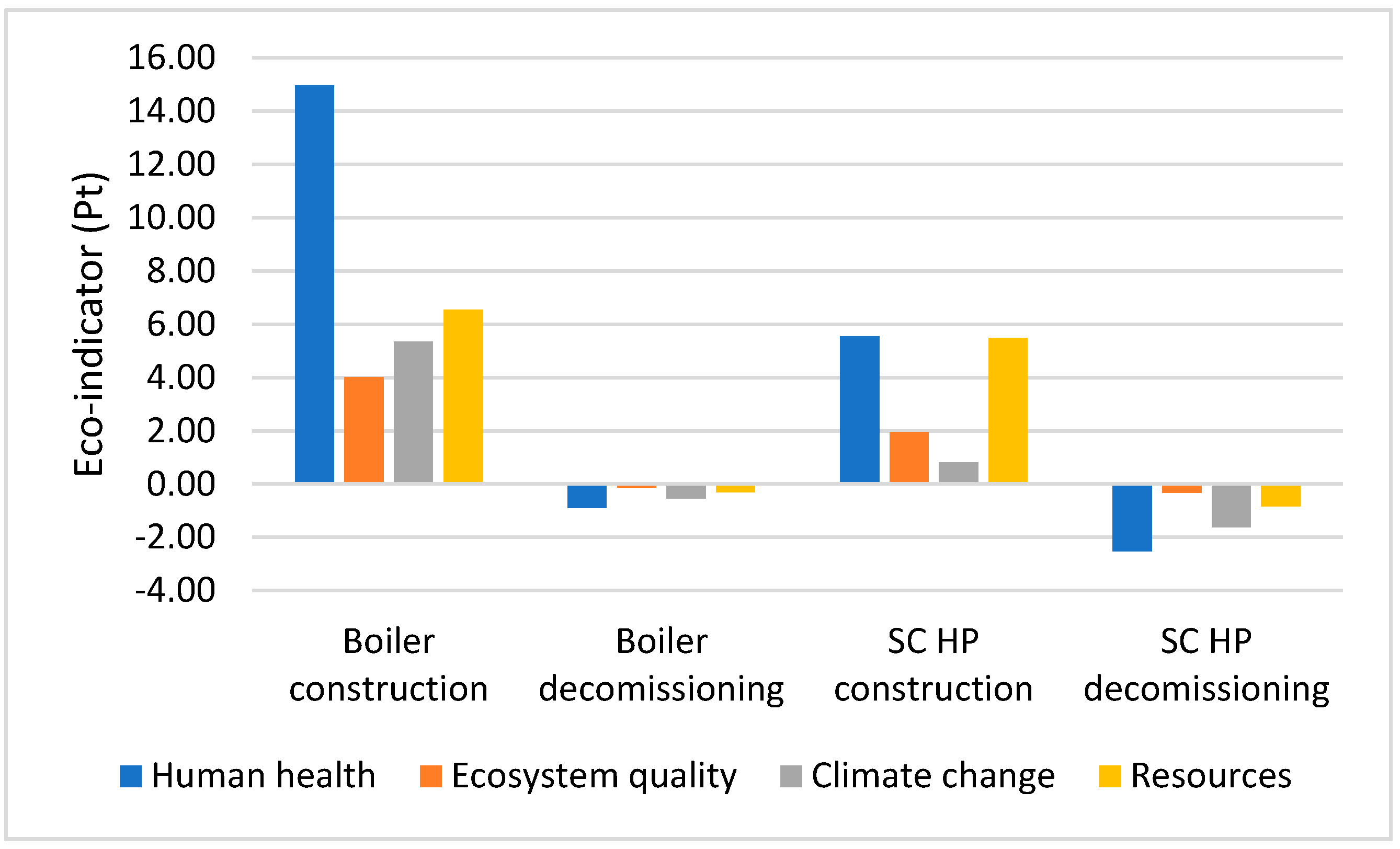
Figure 11 shows the comparison of the manufacturing and decommissioning phases of the heat pump and the boilers on the Eco-indicator scale. It can be seen from the graph that the impact categories showed negative values during the decommissioning phase. This is because 90% of the boiler and heat pump materials are being recycled and hence have a beneficial effect on the environmental indicator.
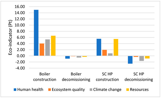
Figure 11.
Characterization of the damage from the construction or decommissioning of the boilers and the construction or decommissioning of the SC HP. (Unit: Pt.)
Note that for the new and larger 750 kW heat pump, a COPh of 1.7–1.9 is expected which will, however, not very much affect the comparison between the heating technologies presented here. The actual differences with the fossil fuel boilers will be somewhat smaller because of this slightly smaller COPh.
4. Conclusions
The aim of the study is to compare an SC HP with heating technologies that use various fuels (oil, natural gas, biomass, and bio-oil) and to identify which heat pump has the lowest environmental impact considering its life cycle from the development to the final use and decommissioning afterwards. The assessment of the models’ life cycles showed that the SC HP is more eco-friendly and gives lower exergy losses over its lifetime than the other technologies.
SC HPs should be a part of the solution to today’s most important environmental challenges—global warming and climate change. Adding the CO2 capture technology to the (fossil) fuel-fired heating systems will obviously add process hardware, besides most likely a CO2 scrubbing solvent, and give an energy penalty presented as exergy losses. This will add to the life cycle footprint for most impact categories while lowering it for the climate change impact category.
For future work, a comparison on economic sustainability should be made (as is scheduled as the next step of the research). This will present a broader image of how the SC HP system performs compared to the NGB, the fossil fuel OB, and the biofuel boiler in terms of environmental and economic impacts combined. In addition, the effects of a somewhat different COPh may be considered based on the future data obtained from the 750 kW SC HP.
Author Contributions
Conceptualization, R.Z., U.K., L.S. and T.-M.T.; methodology, U.K., L.S. and R.Z.; software, U.K. and R.Z.; validation R.Z., L.S. and T.-M.T.; formal analysis, U.K., R.Z. and L.S.; investigation, U.K., R.Z., L.S. and T.-M.T.; resources, U.K., R.Z., L.S. and T.-M.T.; data curation, U.K., R.Z., L.S. and T.-M.T.; writing—original draft preparation, U.K.; writing—review and editing, R.Z., L.S. and T.-M.T.; visualization, L.S. and T.-M.T.; supervision, R.Z. and T.-M.T.; project administration, R.Z. and T.-M.T.; funding acquisition, R.Z. and T.-M.T. All authors have read and agreed to the published version of the manuscript.
Funding
The work described in this paper is partly financed by the European Commission under the Horizon 2020 Fast Track to Innovation programme with the grant agreement number 831062 (2019–2021).
Institutional Review Board Statement
Not applicable.
Informed Consent Statement
Not applicable.
Data Availability Statement
Data sharing is not applicable to this article.
Acknowledgments
The authors thank the project co-workers at Olvondo Technology and AstraZeneca in Norway and Sweden for input data and other support.
Conflicts of Interest
The authors state no conflict of interest.
Disclosures
One of the authors, T.-M.T., is working in a company developing and marketing the heat pump being studied. U.K., R.Z. and T.M.T. are participating in an EU-financed project developing the technology.
References
- Regufe, M.; Pereira, A.; Ferreira, A.; Ribeiro, A.; Rodrigues, A. Current Developments of Carbon Capture Storage and/or Utilization–Looking for Net-Zero Emissions Defined in the Paris Agreement. Energies 2021, 14, 2406. [Google Scholar] [CrossRef]
- Fleiter, T.; Steinbach, J.; Ragwitz, M. Mapping and Analyses of the Current and Future (2020–2030) Heating/Cooling Fuel Deployment (Fossil/Renewables); Report submitted to European Commission; European Commission: Brussels, Belgium, 2016. [Google Scholar]
- Jakob, M.; Reiter, U.; Krishnan, S.; Louwen, A.; Junginger, M. Heating and cooling in the built environment. Technol. Learn. Transit. Low-Carbon Energy Syst. 2020, 189–219. [Google Scholar] [CrossRef]
- EHPA Secretary General Thomas Nowak Talk to SETIS (Strategic Energy Technologies Information System). Available online: https://setis.ec.europa.eu/publications/setis-magazine/low-carbon-heating-cooling (accessed on 27 January 2021).
- The European Heat Pump Market and Statistics Report 2020. Available online: https://www.ehpa.org/market-data/market-report-2021/ (accessed on 6 December 2021).
- Annual Amount of Heat Pumps in Operation in Sweden from 2013 to 2019. Available online: https://www.statista.com/statistics/864011/heat-pumps-in-operation-sweden/ (accessed on 19 November 2021).
- Finnish Heat Pump Association. Available online: https://www.sulpu.fi/ (accessed on 10 September 2021).
- Profile of Heating and Cooling Demand in 2015. Available online: https://heatroadmap.eu (accessed on 27 November 2021).
- Tveit, T.-M.; Khan, U.; Zevenhoven, R. Environmental impact of high temperature industrial heat pumps from a global warming potential (GWP) perspective. In Proceedings of the Industrial Efficiency 2020—Accelerating Decarbonization, Gothenburg, Sweden, 14–16 September 2020. [Google Scholar]
- HighLift Series SPP 4-106 Stirling Cycle-Based Heat Pump. Available online: http://www.olvondotech.no/the-technology/ (accessed on 10 January 2021).
- Lewandowska, A.; Kurczewski, P.; Joachimiak-Lechman, K.; Zabłocki, M. Environmental Life Cycle Assessment of Refrigerator Modelled with Application of Various Electricity Mixes and Technologies. Energies 2021, 14, 5350. [Google Scholar] [CrossRef]
- SIMAPRO. Available online: https://simapro.com/ (accessed on 20 May 2020).
- EcoInvent. EcoInvent Database. Available online: https://www.ecoinvent.org/ (accessed on 3 July 2021).
- Szargut, J.; Morris, D.R.; Steward, F.R. Exergy Analysis of Thermal, Chemical and Metallurgical Processes; Hemisphere Publishing Co.: New York, NY, USA, 2005. [Google Scholar]
- Stougie, L.; Valero Delgado, A.; van der Kooi, H. Sustainability assessment of power generation systems by applying exergy analysis and LCA methods. In Proceedings of the ECOS 2015—The 28th International Conference on Efficiency, Cost, Optimization, Simulation and Environmental Impact of Energy Systems, Pau, France, 30 June–3 July 2015. [Google Scholar]
- Haberl, H.; Erb, K.H.; Krausmann, F.; Gaube, V.; Bondeau, A.; Plutzar, C.; Gingrich, S.; Lucht, W.; Fischer-Kowalski, M. Quantifying and mapping the human appropriation of net primary production in earth’s terrestrial ecosystems. Proc. Natl. Acad. Sci. USA 2007, 104, 12942–12947. [Google Scholar] [CrossRef] [PubMed] [Green Version]
- Abaza, H.; Bisset, R.; Sadler, B. Environmental Impact Assessment and Strategic Environmental Assessment: Towards an Integrated Approach; Economics and Trade Branch Division of Technology, Industry, and Economics United Nations Environment Programme Report; 2004; ISBN 92-807-2429-0. Available online: http://www.gdrc.org/uem/eia/textONUBr.pdf (accessed on 15 November 2021).
- Eco-Indicator 99 Manual. Available online: https://www.pre-sustainability.com/news/eco-indicator-99-manuals (accessed on 6 January 2021).
- Tveit, T.-M.; Johansson, M.N.; Zevenhoven, R. Environmentally friendly steam generation using VHTHPs at a pharmaceutical research facility. In Proceedings of the 13th IEA Heat Pump Conference, Jeju, Korea, 26–29 April 2021; pp. 90–98. [Google Scholar]
- Khan, U.; Zevenhoven, R.; Tveit, T.-M. Evaluation of the environmental sustainability of a Stirling cycle-based heat pump using LCA. Energies 2020, 13, 4469. [Google Scholar] [CrossRef]
Publisher’s Note: MDPI stays neutral with regard to jurisdictional claims in published maps and institutional affiliations. |
© 2021 by the authors. Licensee MDPI, Basel, Switzerland. This article is an open access article distributed under the terms and conditions of the Creative Commons Attribution (CC BY) license (https://creativecommons.org/licenses/by/4.0/).

