Abstract
Worldwide need for renewable energy sources increases significantly with the drastic negative greenhouse effects of climate change. This study considers a water-cooled hybrid thermo-electric panel (PV/T) which contributes to better harvesting of solar energy. A numerical CFD model was developed for power generation of a standard PV panel as well as for a water-based PV/T system laminated with polymer matrix composite (PMC) materials, and user-defined functions (UDFs) were developed and integrated with the CFD model to implement exact boundary conditions. Experimentation under daily weather conditions was carried out in order to validate the numerical CFD model by measuring the surface temperatures of PV and PV/T systems as well as the temperatures of the water inlet and outlet of the cooling system. The results show that the maximum and minimum deviations of the surface temperature between numerical and experimental studies matched well compared with the studies performed in the literature. Moreover, the numerical model had a rapid response to temperature changes of PV and PV/T modules under sudden weather changes (cloudy/sunny). It was shown that the electrical efficiency of the cooled PV/T module can achieve 20.8% in addition to a thermal efficiency of 53.5%. The current study is a validation of the performance of polymer composite laminated water-cooled PV/T systems under daily weather conditions.
1. Introduction
Energy demand in the world causes increased CO2 emissions and consuming fossil fuels [1,2]. Renewable energy sources (RES) are becoming more considered to cope with the increased demand and the scarcity of fossil sources. They are clean and unlimited and have a significant positive impact on climate change. Governments make decisions to increase the use of renewable energy sources [3]. In addition to being eco-friendly, the cost of RES is expected to be reduced [4]. Solar energy plays a key role among RES due to its availability and cost-effectiveness and is becoming dominant in the ecological balance of the world [5].
In recent years, the electrical conversion efficiency of solar panels has exceeded 20%. Solar panels store the remaining energy as heat energy which causes an increase in their temperature and a reduction in their efficiency. PV/T systems were developed to capture heat energy in the solar panels. The first thermally developed PV panel phenomena were developed in 1974. The overall efficiency of the PV/T systems developed in the last 10 years has increased significantly [6,7]. According to the Fraunhofer ISE photovoltaics report, the overall performance of the PV system has increased strongly. Before the 2000s, the performance ratio of PV systems was about 70% and today it is in the range of 80% to 90% [8]. The performance ratio (PR) is a measure of the quality of a solar PV plant independent of location and is often described as a quality factor. PV/T systems can be classified into three main categories: liquid-based, air-based, and bi-fluid-based. Liquid-based PV/T systems have a wide range of applications for industrial and personal purposes. In addition, this type of PV/T system has many advantages, such as high heat transfer away from the PV module. The most common types of liquid-based PV/T systems are seen as water-based, nano-fluid-based, and phase change material (PCM)-based [9]. PCM-based PV/T systems have a unit on the back side of the PV panel which contains PCM material to transfer heat away from the PV panels. PCM materials have a high specific heat capacity and thermal conductivity. During the PCM unit application, water tubes also use the inside of the PCM material [10]. The material definition of PCM can be seen as the most critical step during the application because phase change materials have a wide thermophysical properties range. One of the most commonly used PCMs is known as paraffin wax [11]. The most common disadvantages of PCM application are known as PCM leakage, initial and maintenance cost, and natural cooling energy storage during the nighttime [12,13]. Nano-fluid-based PV/T systems use nano-fluids as coolants. These collector types have better heat transfer performance between the heat energy source and coolant [14]. However, nano-fluid-based PV/T systems have many disadvantages. These are the cost of the nanoparticles and increasing pumping power needs [15]. This study focuses on water-based PV/T systems. The tube-and-sheet type of water-based PV/T system was investigated and compared without the tube-and-sheet collector under two different mass flow rates by Dubey et al. The electrical efficiency difference between PV and PV/T systems was obtained at 0.4% [16]. An improved heat exchanger design for air-based PV/T systems was presented by Hussain et al. This heat exchanger design consisted of many honeycomb channels. The air-based PV/T system was tested under different mass flow rates and solar irradiation using the solar simulator. The maximum thermal efficiency of the PV/T system was obtained as 60% [17]. Water-based and bi-fluid-based types of PV/T systems were investigated simultaneously by Atmaca et al. Total efficiencies of water-based PV/T systems were observed between 20% and 40%. In addition, total efficiencies of bi-fluid-based PV/T systems were observed between 60% and 90%. It was seen that the total efficiency of the bi-fluid-based PV/T systems is better than the single usage [18].
The current study was implemented in Izmir, Turkiye (lat: 38°, lon: 27°, GMT: +3). Electrical and thermal efficiencies of the water-based PV/T system laminated with polymer matrix composites (PMC) materials were investigated under daily climate changes and were simultaneously compared with a standard PV module. In addition, a 3D numerical CFD model was developed to validate measured temperature distributions of PV and PV/T systems. To make a powerful estimation, user-defined functions (UDFs) were developed with defined boundary conditions and integrated with the numerical CFD model. Results showed that the developed CFD model and UDFs perfectly matched with experimental outcomes.
2. Materials and Methods
2.1. Problem Description
Silicon-based PV cells are easy to supply, cost-effective, and have a relatively long lifetime. Monocrystalline PV cells have a longer efficient life cycle than polycrystalline PV cells. Under all these conditions, SunPower C60 mono-silicon PV cells were chosen to be used in the present study. The maximum power of the non-laminated PV cell is 3.34 (Wp), the electrical efficiency is 21.8%, and the maximum voltage at the maximum power point is 0.574 (V) [19,20]. In this study, one PV cell (C60 m-Si) was used for each PV and PV/T module. Conventional types of PV panels are laminated with the usage of many materials. Glass, ethylene vinyl acetate (EVA), anti-reflective coating (ARC), and Tedlar materials are used for the lamination of the conventional PV cells [21]. The average thickness of this type of lamination technique is around 4 mm, which creates a heat conduction resistance to transferring the stored heat energy inside of the PV cell [22]. Therefore, a new lamination technique is tested in the present study. PV and PV/T systems are designed to have one PV cell on each, and these non-laminated m-Si PV cells are laminated with polymer matrix composite (PMC) materials. PMC structures are composed of two or more different materials with significantly separate physical or chemical properties that, when combined, produce a material with different characteristics from the individual components [23,24]. In this study, it was decided to use epoxy resin as matrix material and glass fibers as reinforcement material for the PMC structure. Thin fibers were used for high thermal conduction, and glass fiber reinforcement materials have about 0.18 (W/mK) thermal conductivity coefficient [25].
In the choosing of epoxy resin, the refractive index values were considered primarily, whereas for reinforcement material, besides refractive index value, thermal conductivity was considered. The mechanical properties of evaluated epoxy resins for lamination are shown in Table 1. F-1564 Epoxy has low viscosity and high elasticity. Its color is almost transparent. Crystal Clear 200 Epoxy (CC200) has a low refractive index and low viscosity. Polipol 354 is fully transparent, but its refractive index is high with the chosen epoxy resins. For that reason, F-1564 epoxy resin was preferred for use as the matrix material for the lamination of PV cells.

Table 1.
Properties of matrix materials [23].
Seamless glass fiber (YCL J-M) is the preferred reinforcement material and has low strength but provides similar distribution of PMC components along the surface and a thinner layer on the PV cell [24]. In the present PMC lamination of PV cells, one layer of glass fiber was used on the sun-facing side of PV cells and three layers of glass fiber were used on the back side of PV cells. Molding of PMCs has different methods. In this study, the vacuum-assisted resin transfer molding (VARTM) method was preferred for the laminating process. In this method, liquid resin with hardener from an external reservoir is drawn into the component by vacuum, so homogeneous dispersion of the epoxy resin is provided to the structure and excess resin usage is prevented [24].
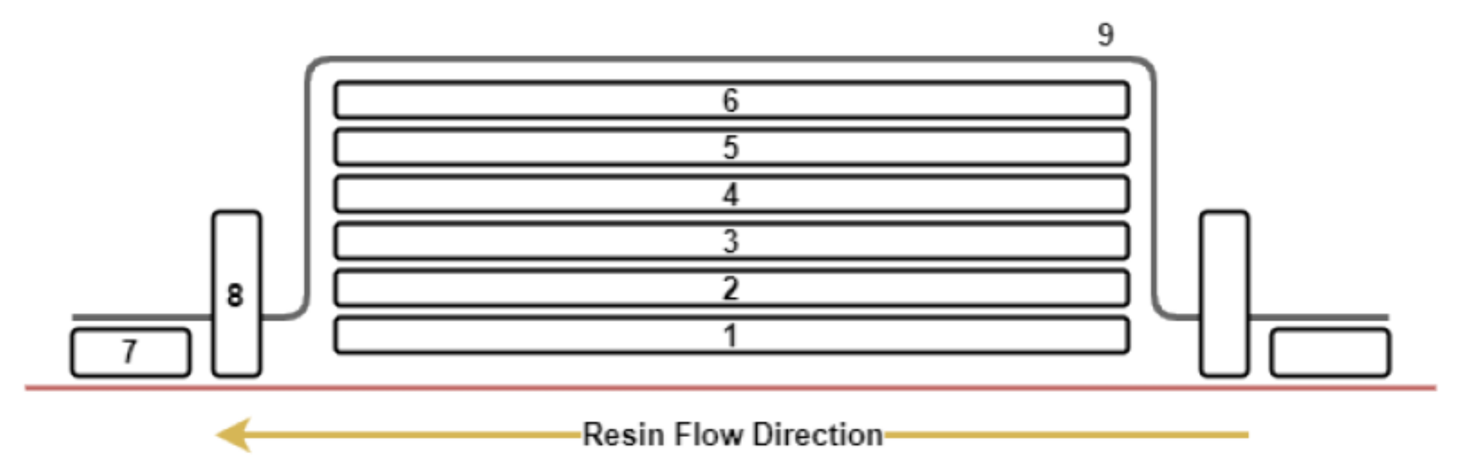
In Figure 1 and Table 2, the preferred materials during VARTM are detailed. Besides desired product layers (PV cell and glass fiber layers), release film layers are used for releasing the product from other layers. In this production, Polivaks SV-6 liquid release agent was applied to the production table surface additionally. The thickness of the PMC laminated PV cells was measured as 1 mm. Thus, the length of the heat conduction resistance was decreased, and the heat transfer ability of the PMC laminated PV cells was improved [26].
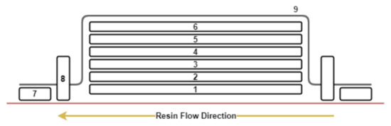
Figure 1.
Schematic illustration of the vacuum-assisted resin transfer molding (VARTM) process.
Table 2.
Components of the VARTM lamination process.
Cross sections of the PV and PV/T modules, and the layout of the water-based cooling system, are shown in Figure 2a,b. A serpentine water-based cooling pipe was bent six times, and copper with 1 mm thickness was used to obtain high heat transfer. Each PV cell module was thermally isolated using XPS foam to prevent heat losses from the lateral and bottom faces of the PV cell module. The mass flow rate of the pump was 0.025 kg/s, and the efficiency was 80% at 300 K (26.85 °C) water inlet temperature. Components of the PV/T and PV modules and their physical properties are shown in Table 3. In the PV/T system, a 3 mm thickness of the metal sheet (copper) and cooling pipe (copper) were used to improve heat transfer from the PV cell.
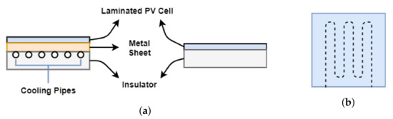
Figure 2.
A cross section of the PV/T and PV modules (a), and layout of the water-type cooling pipe (b).
Table 3.
Components of PV/T and PV modules and their physical properties.
Thermophysical properties of materials used in PV/T and PV modules are shown in Table 4. Copper was preferred for the metal sheet and water-cooling pipe to achieve high heat transfer from the PV module. Specific heat is also an important thermophysical property for insulators. In this study, XPS foam was used to achieve insulation between the lateral and bottom interfaces between PV modules and the environment. In addition, the thermophysical properties of the chosen XPS foam were verified with the literature and producers’ specifications.
Table 4.
Thermophysical properties of the materials used in PV/T panel [27,28,29,30,31].
Technical specifications, accuracy, and measurement ranges of the components of the used sensors are shown in Table 5.
Table 5.
Technical specifications of the measurement instruments and their error rates (per unit).
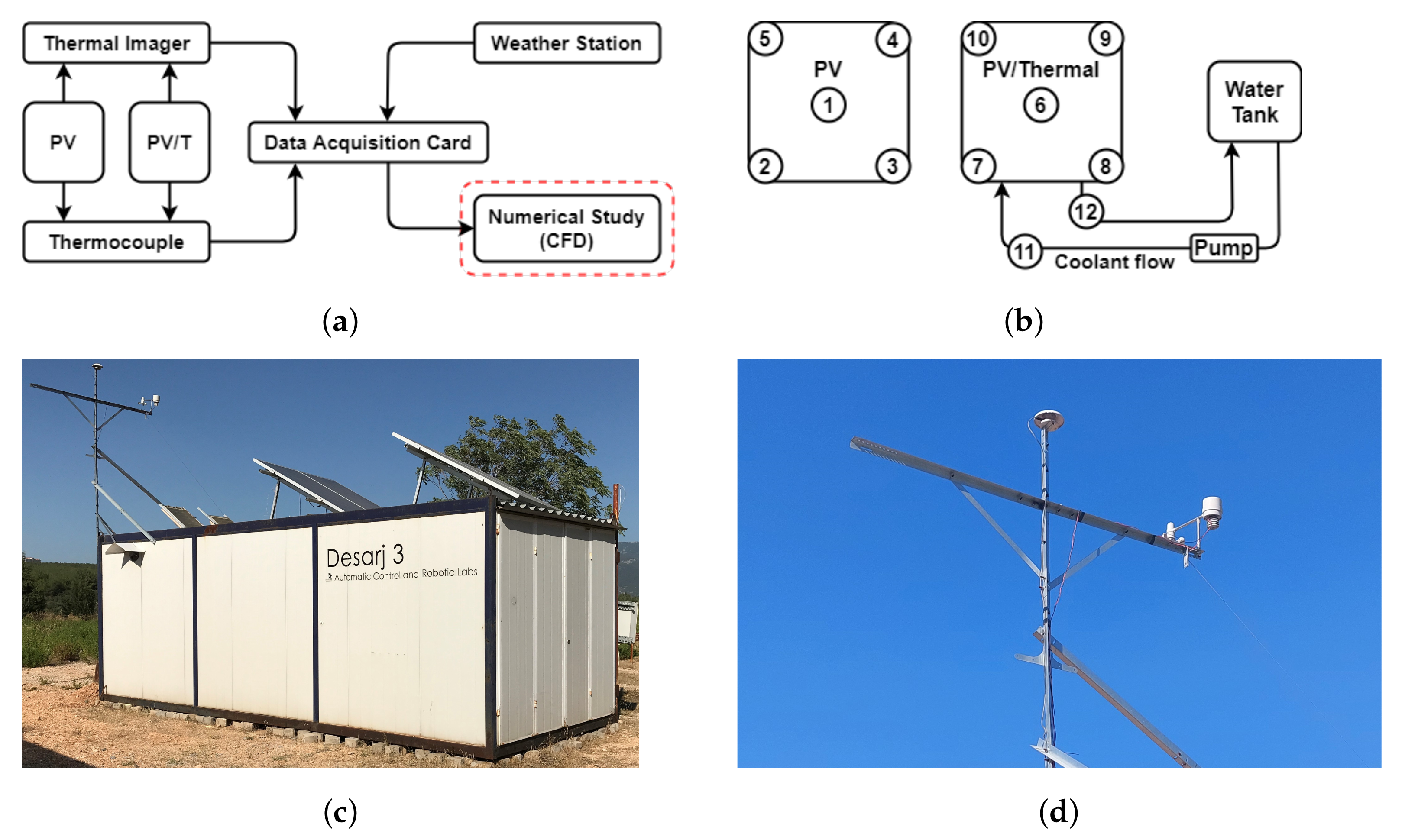
Experimental studies were performed for nine hours a day. Solar irradiation (W/m), wind speed (km/h), humidity (%), ambient temperature (°C), and temperatures (°C) of PV/T and PV modules were measured and logged simultaneously. Workflow of the measurement instruments and locations of thermocouples on PV and PV/T systems are shown in Figure 3a,b. Depending on the measurement instruments diagram (Figure 3a), temperature distributions of PV/T and PV systems were measured using thermocouples and validated with an infrared camera. Concurrently, the solar irradiation, ambient temperature, humidity, and wind speed were recorded using a weather station. In addition, the temperature in the four corners and in the center of each PV/T and PV module, as well as the temperature changes of entry and exits of the water-type cooling pipe in the PV/T module, were measured to obtain the thermal efficiency changes of the PV/T system.

Figure 3.
The working diagram of measurement instruments (a), temperature measurement points with thermocouples on the PV/T and PV modules (b), isometric view of the experimental environment (c), and the weather station (d).
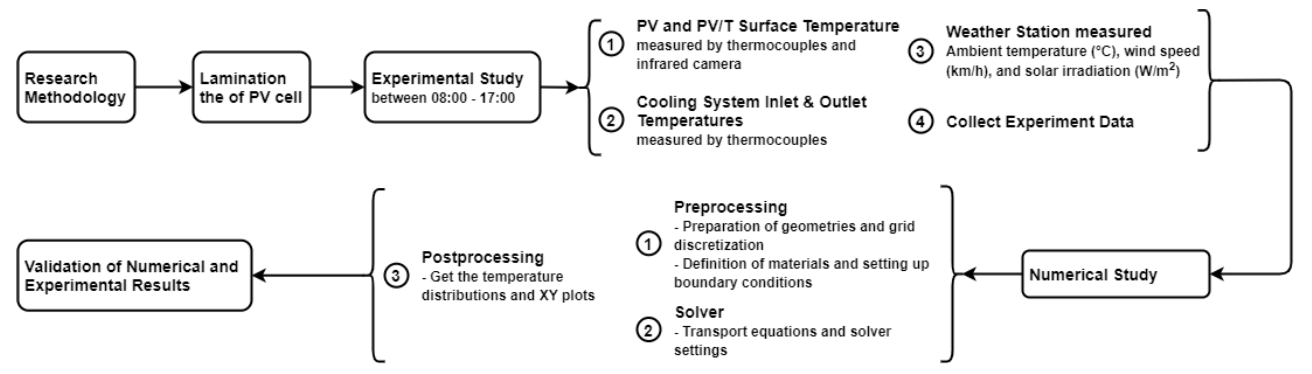
The lamination of PV cells with PMC materials and its application in water-based PV/T systems is seen as a scientific gap. The overall framework of the current study is summarized in Figure 4. This research study started with the lamination of PV cells and the preparation of the experimental environment. The experimental study was followed by numerical studies to validate the developed CFD model.

Figure 4.
Overall framework of this study.
2.2. Boundary Conditions
Boundary conditions applied to the top surface of the PV and PV/T modules are shown schematically in Figure 5. The bottom and lateral faces of PV and PV/T modules are assumed as adiabatic. For that reason, the heat transfer is assumed to only be from the sun-facing side of the modules. In addition, the mass flow inlet to the water-type cooling pipe was fixed to a constant value of 0.025 kg/s.
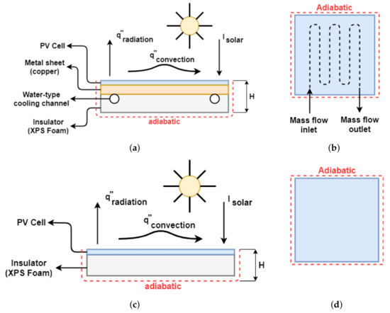
Figure 5.
Boundary conditions of PV/T (a,b) and PV (c,d) modules.
Applied energy balance on the surface yields and the energy balance are shown in Equation (1).
where is the incident solar irradiation on the top surfaces of PV and PV/T. and are the convective and radiative heat losses from modules. The radiative heat loss is evaluated from the Stefan–Boltzmann law and can be represented as in Equation (2) [32].
where represents the surface temperature of the laminated PV cells. represents the sky temperature and is evaluated from the Swinbank equation (Equation (3)) [32].
where represents the ambient temperature. The convective heat loss is evaluated from Equation (4).
where is the heat transfer coefficient from the laminated PV cell. The heat transfer coefficient is given by Equation (5) [32].
where and represent natural and forced convections, expressed in Equations (6) and (7).
where represents the wind speed in m/s. To implement all correlations and manage constants (, , , ), user-defined functions (UDF) were preferred in numerical studies.
2.3. Solution Method
2.3.1. Governing Equations
Navier–Stokes equations based on the conservation of mass, momentum, and energy represent the governing equations of the CFD model. Additionally, thermophysical properties of materials are assumed as constant, and all exterior surfaces of PV and PV/T modules except the sun-facing side are assumed as thermally isolated. The realizable k-epsilon turbulence model is used to determine high flow rates, and the SIMPLE scheme is preferred to obtain pressure–velocity coupling.
For continuity:
For x-momentum:
Newton’s second law represents the motion of a body under changeable forces, and the conservation of momentum is obtained by this law. Conservation of x-axis momentum is shown in Equation (9) and the y- and z-axes of conservation of momentum equations can be found in the ANSYS Fluent Theory Guide [33].
For energy:
where is the turbulent viscosity and is defined as
The realizable turbulence model was used to simulate the fluid flow and circulation inside of the serpentine cooling pipe [34]. In addition, the SIMPLE algorithm was preferred as a pressure–velocity coupling scheme [35]. Mathematical expressions of the preferred turbulence model can be found in the theory guide of the software package [33]. No-slip condition was applied to all the walls. The energy equation of the PV cell domain is as follows:
where and are source terms that exemplify the electrical power output and heat generation [36]. The source terms in Equation (12) are expressed as
where represents the thickness of PV cell.
where and represent the absorptivity of the PV cell and transmissivity of the lamination layer of the PV cell. Absorptivity and transmissivity values were assumed as 0.9 and 0.95 [37].
where represents the electrical efficiency of the PV cell. In this study, the value of of the m-Si type PV cell was set to 21.8%, and the temperature coefficient () of the PV cell was taken as 0.00392, with the reference temperature as 298 K. To guarantee independence in the results of the developed CFD model, different mesh structures with different grid sizes were investigated from 0.55 million to 1.25 million mesh elements. The convergence depends on particular levels of accuracy that were defined as for the mass and momentum equations, and for the energy equation.
2.3.2. System Efficiency Correlations
In this study, the electrical, thermal, and overall efficiencies were calculated. The electrical efficiency of the PV and PV/T modules were evaluated from Equation (15). In addition, thermal efficiency was defined as
The thermal efficiency of the water-type PV/T system is shown in Equation (16). and represent the PV panel area and thermal power [38].
where and represent water inlet and outlet temperatures, and represents the mass flow rate of the cooling channel. The overall efficiency of the PV/T module is expressed as
where and represent the electrical and thermal efficiencies.
3. Results and Discussion
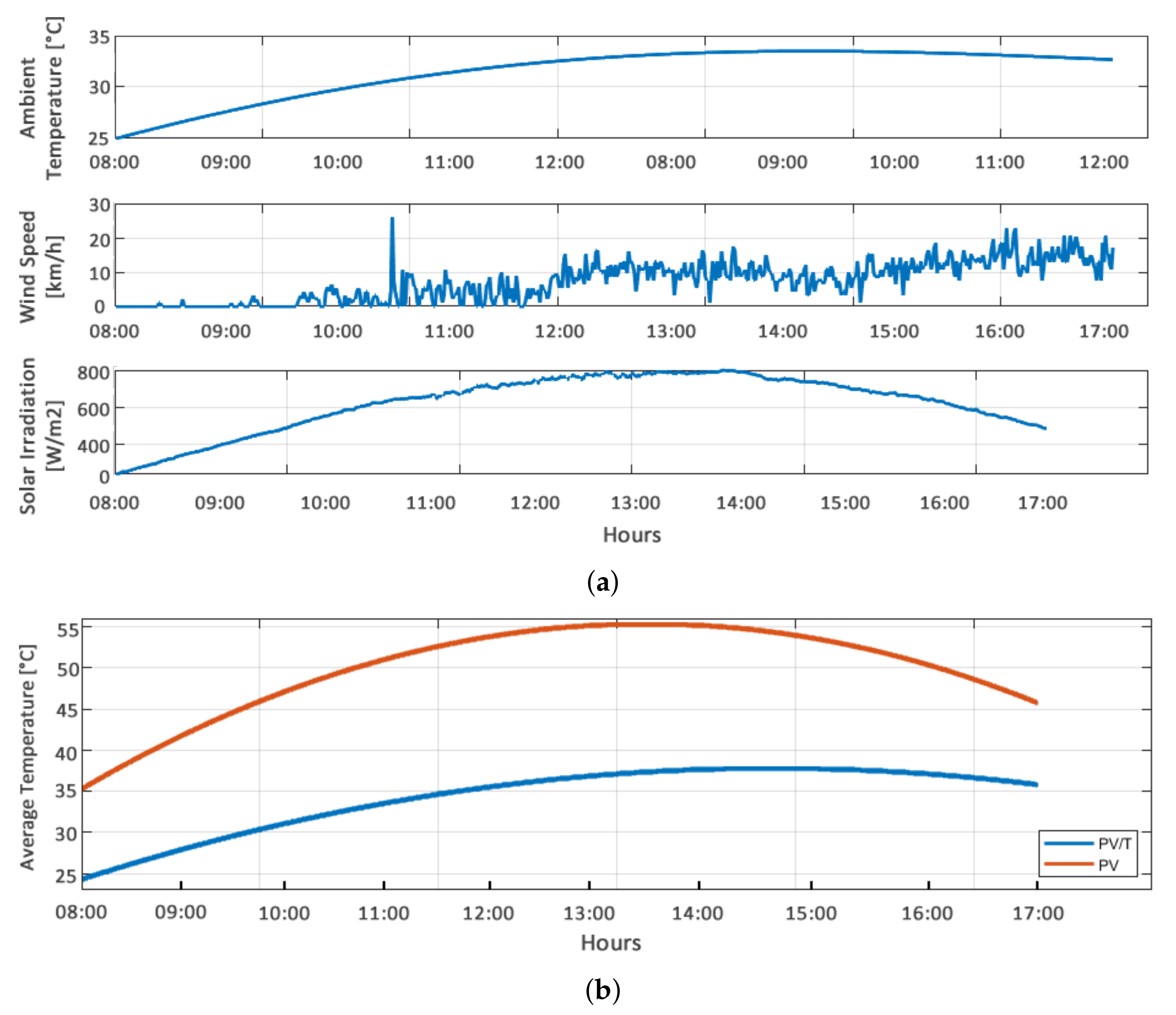
In this study, electrical and thermal efficiencies of the PMC laminated PV and PV/T systems were investigated under daily climate and validated using the CFD model. The experimental study was performed on 23 June 2021, at the Solaris Solar Car Project workshop (latitude: 38° and longitude: 27°, GMT: +3) in Izmir, Turkiye. The experiment lasted 9 h, started at 8 a.m., and was completed at 5 p.m. Figure 6a shows the weather data that were logged during the experiment simultaneously. Maximum solar irradiation was measured as 800 W/m. Ambient temperature and wind speed values were measured from 20 °C to 35 °C, and from 0 to 25 km/h.
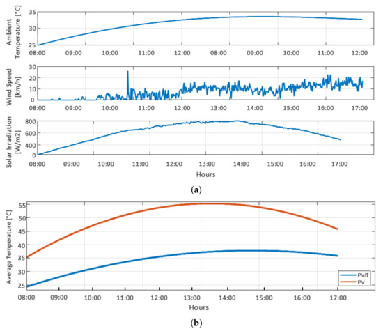
Figure 6.
Logged weather data on 23 June 2021 (a) and simultaneous temperature changes of PV and PV/T modules (b).
PV and PV/T modules temperatures were measured from five different points (four corners and one center). Temperature distributions of PV and PV/T modules are shown in Figure 6b. The maximum average temperatures of PV and PV/T modules were observed as 55.95 °C and 37.29 °C. In addition, the temperatures at the inlet and outlet of the water-based PV/T were measured simultaneously. The maximum water inlet and outlet temperatures of the water-type cooling system were obtained as 31.98 °C and 33.22 °C.
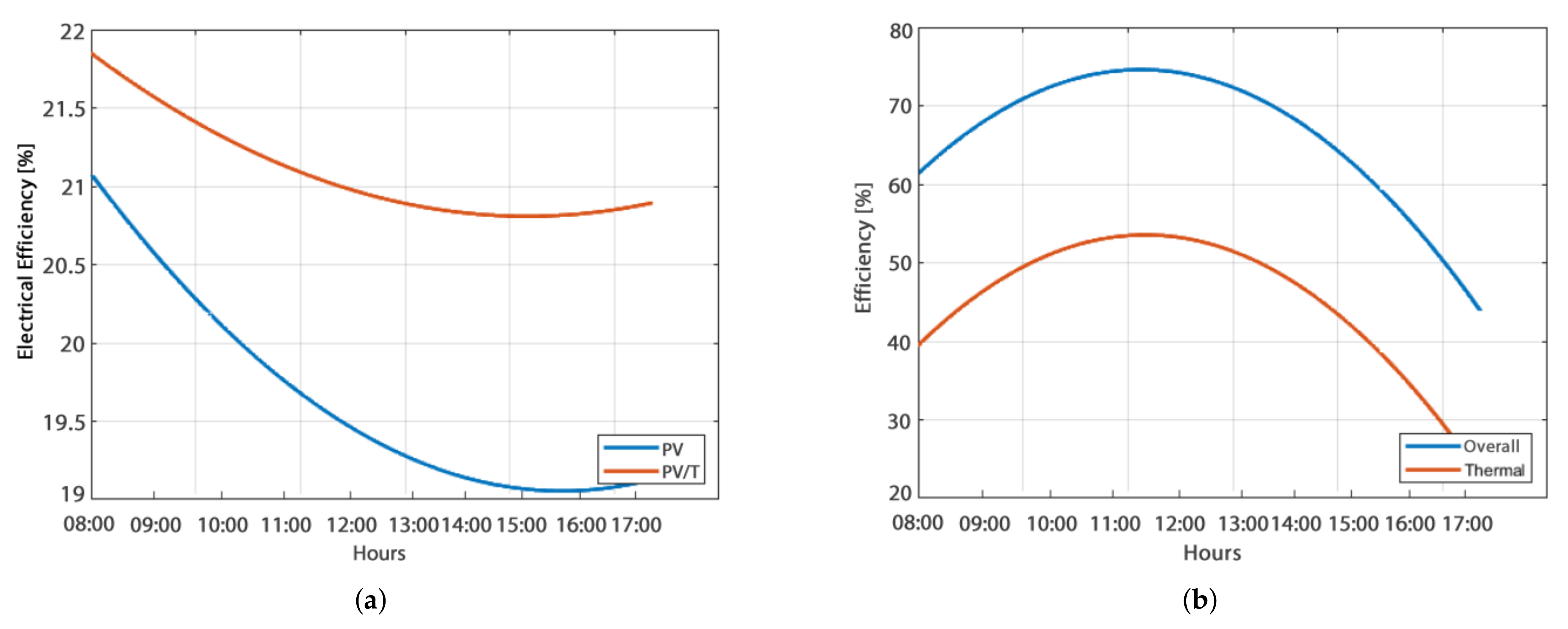
The electrical and thermal efficiencies of PV and PV/T modules were calculated. Electrical and thermal efficiencies of PV and PV/T modules are shown in Figure 7. Electrical efficiencies of the PV/T module varied between 20.8% and 21.8%, whereas the electrical efficiencies of the PV module varied between 19% and 21%. In addition, thermal efficiencies of the PV/T module varied between 23.9% and 55.2%. The total efficiency of the PV/T cell varied between 75% and 45%.
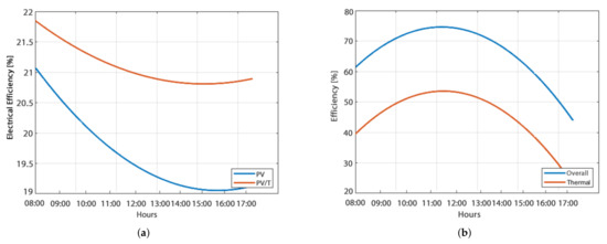
Figure 7.
Electrical efficiencies of PV and PV/T modules (a) and overall thermal efficiencies of PV/T modules (b).
In the morning and afternoon, convective and radiative heat transfer from the PV/T module is lower than at noon (between 11.30 a.m. and 2 p.m.) because the surface temperatures of PV cells were close to the ambient conditions. At noon, it was observed that the thermal efficiency increased with the increasing temperature difference between the PV/T module and the water-based cooling system (Figure 7b).
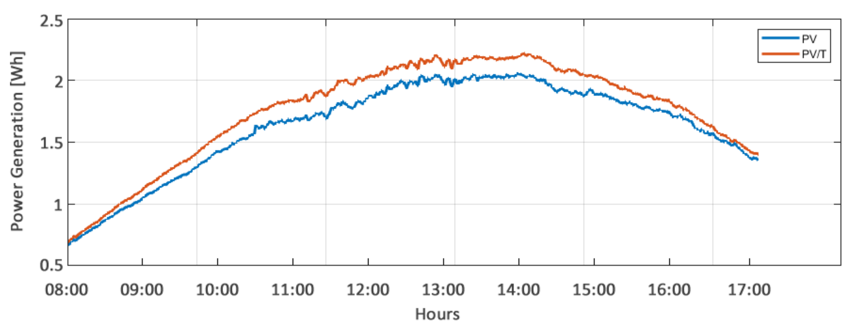
Theoretical power generations of PV and PV/T modules are shown in Figure 8. The maximum power generation was obtained during the sixth hour (between 1 p.m. and 2 p.m.) for PV and PV/T modules. During this period, power generations of PV/T and PV reached 2.2 Wh and 2 Wh. This means a 0.2 Wh difference from each other. The power generation of non-laminated PV cells used in the current study was indicated as 3.34 Wh under 1000 W/m solar irradiation. Power generation losses were expected because the PV cells used in this study were laminated. In addition, the maximum solar irradiation was logged as 800 W/m.
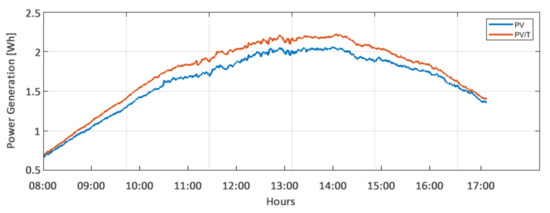
Figure 8.
Hourly power generation of the PV and PV/T modules.
Comparisons between the numerical and experimental temperatures of PV and PV/T modules are shown in Figure 9a,b. In addition, the thermocouple measurements on PV and PV/T modules were validated by the infrared camera each hour (Figure 10). Numerical study results perfectly matched with the experiment ones. It was seen that the temperature difference between the numerical and experimental studies varied between 0.3 °C and 2.2 °C. This means a 0.2% maximum difference in electrical efficiency. For that reason, results that were obtained from the developed UDFs and the numerical CFD model are acceptable for the estimation of the power generation of water-based PV/T systems.
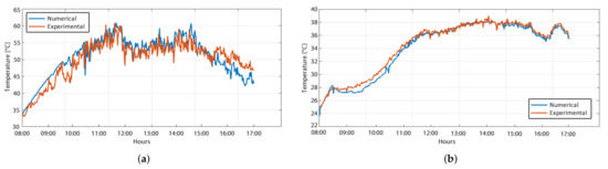
Figure 9.
Temperature changes obtained by numerical and experimental studies on PV (a) and PV/T (b) modules.
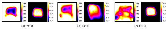
Figure 10.
Temperature changes of the PV (right) and PV/T (left) modules which were taken by infrared camera.
4. Conclusions
In this study, a CFD model was developed to estimate electrical, thermal efficiencies, and power generation for water-type PV/T systems laminated with PMC materials. In addition, UDFs were developed to implement exact boundary conditions and integrated with the CFD model. The electrical efficiency difference between the numerical model and experiments was as low as 0.2%. In addition, maximum and minimum temperature differences were obtained between 0.3 °C and 2.2 °C. This study also contributes to the new lamination technique of PV modules and its effect on water-cooled PVT panels to pioneer further PVT designs.
This research has limitations, challenges, and future prospects:
- Electrical and thermal efficiencies of PV and PV/T modules laminated with PMC materials were investigated by considering only temperature measurements. Additional sensors to measure currents and voltages will improve the estimation of effective power generation.
- Water flow was fixed to a constant value. The flow value must be optimized with respect to the specific application.
- Extension of one cell module to multiple cells should be considered to optimize cell combination and cooling architecture.
- The numerical model developed in the current study should be tested for other liquid-based and air-based PV/T systems.
Author Contributions
The paper was a collaborative effort between the authors. T.B.K., A.G. and A.R. contributed collectively to the examination of PV/T application, experiments, and manuscript preparation. All authors have read and agreed to the published version of the manuscript.
Funding
This research received no external funding.
Institutional Review Board Statement
Not applicable.
Informed Consent Statement
Not applicable.
Data Availability Statement
Not applicable.
Acknowledgments
The authors would like to thank the Solaris Solar Car Project for its collaboration in setting up the experimental environment and the implementation of the embedded systems design and setup.
Conflicts of Interest
The authors declare no conflict of interest.
Abbreviations
The following abbreviations are used in this manuscript:
| PV | Photovoltaic |
| PV/T | Photovoltaic thermal |
| PMC | Polymer matrix composite |
| CFD | Computational fluid dynamics |
| ARC | Anti reflecting coating |
| EVA | Ethylene vinyl acetate film |
| PR | Performance ratio |
| Specific heat capacity (J/kgK) | |
| Density (kg/m) | |
| k | Thermal conductivity coefficient (W/mK) |
| Solar irradiation (W/m) | |
| Convective heat transfer (W/m) | |
| Radiative heat transfer (W/m) | |
| Stefan–Boltzmann constant | |
| Surface temperature (°C) | |
| Sky temperature (°C) | |
| Ambient temperature (°C) | |
| Heat transfer coefficient (W/m °C) | |
| Natural heat transfer coefficient (W/m °C) | |
| Forced heat transfer coefficient (W/m °C) | |
| Wind speed (m/s) | |
| Turbulent viscosity (kg/ms) | |
| Electrical power output (W) | |
| Mass flow rate (kg/s) | |
| Electrical efficiency of the PV panel | |
| Reference electrical efficiency of the PV panel | |
| Thermal efficiency of the PV/T module | |
| Total efficiency of the PV/T module | |
| Reference PV temperature | |
| Temperature coefficient | |
| Absorptivity constant | |
| Transmissivity constant | |
| Thickness of PV cell | |
| Thermal power (W) | |
| Surface area (m) | |
| Inlet coolant temperature (°C) | |
| Outlet coolant temperature (°C) |
References
- Ünal, F.; Temir, G.; Köten, H. Energy, exergy and exergoeconomic analysis of solar-assisted vertical ground source heat pump system for heating season. J. Mech. Sci. Technol. 2018, 32, 3929–3942. [Google Scholar] [CrossRef]
- Iodice, P.; d’Accadia, M.D.; Abagnale, C.; Cardone, M. Energy, economic and environmental performance appraisal of a trigeneration power plant for a new district: Advantages of using a renewable fuel. Appl. Therm. Eng. 2016, 95, 330–338. [Google Scholar] [CrossRef]
- Prasad, A.A.; Taylor, R.A.; Kay, M. Assessment of solar and wind resource synergy in Australia. Appl. Energy 2017, 190, 354–367. [Google Scholar] [CrossRef]
- Daabo, A.M.; Mahmoud, S.; Al-Dadah, R.K. The optical efficiency of three different geometries of a small scale cavity receiver for concentrated solar applications. Appl. Energy 2016, 179, 1081–1096. [Google Scholar] [CrossRef]
- Price, L.; du Can, S.D.L.R.; Sinton, S.; Worrell, E.; Nan, Z.; Sathaye, J.; Levine, M. Sectoral Trends in Global Energy Use GHG Emission; LBNL Report; Energy Analysis Department, Environmental Energy Technologies Division, Lawrence Berkeley National Laboratory: Berkeley, CA, USA, 2006; LBNL-56144; 56p. [Google Scholar]
- Zondag, H. Flat-plate PV-Thermal collectors and systems: A review. Renew. Sustain. Energy Rev. 2008, 12, 891–959. [Google Scholar] [CrossRef]
- Das, D.; Kalita, P.; Roy, O. Flat plate hybrid photovoltaic-thermal (PV/T) system: A review on design and development. Renew. Sustain. Energy Rev. 2018, 84, 111–130. [Google Scholar] [CrossRef]
- FraunhoferISE. Fraunhofer Institute for Solar Energy Systems Photovoltaics Report. 2021. Available online: https://www.ise.fraunhofer.de/ (accessed on 20 July 2022).
- Ul Abdin, Z.; Rachid, A. A survey on applications of hybrid PV/T panels. Energies 2021, 14, 1205. [Google Scholar] [CrossRef]
- Hasan, A. Thermal energy storage system with stearic acid as phase change material. Energy Convers. Manag. 1994, 35, 843–856. [Google Scholar] [CrossRef]
- Abbas, Z.; Shahzad, K.; Jamal, S.; Ahmad, M. Paraffin Wax As A Phase Change Material For Thermal Energy Storage: Tubes In Shell Type Heat Exchanger. N. Am. Acad. Res 2018, 1, 39–52. [Google Scholar]
- Zhou, Y.; Zheng, S.; Liu, Z.; Wen, T.; Ding, Z.; Yan, J.; Zhang, G. Passive and active phase change materials integrated building energy systems with advanced machine-learning based climate-adaptive designs, intelligent operations, uncertainty-based analysis and optimisations: A state-of-the-art review. Renew. Sustain. Energy Rev. 2020, 130, 109889. [Google Scholar] [CrossRef]
- Zhou, Y.; Zheng, S.; Zhang, G. Artificial neural network based multivariable optimization of a hybrid system integrated with phase change materials, active cooling and hybrid ventilations. Energy Convers. Manag. 2019, 197, 111859. [Google Scholar] [CrossRef]
- Murshed, S.S.; De Castro, C.N. Superior thermal features of carbon nanotubes-based nanofluids—A review. Renew. Sustain. Energy Rev. 2014, 37, 155–167. [Google Scholar] [CrossRef]
- Sachit, F.; Rosli, M.; Tamaldin, N.; Misha, S.; Abdullah, A. Nanofluids used in photovoltaic thermal (pv/t) systems. Int. J. Eng. Technol. 2018, 7, 599–611. [Google Scholar]
- Dubey, S.; Tay, A.A. Testing of two different types of photovoltaic–thermal (PVT) modules with heat flow pattern under tropical climatic conditions. Energy Sustain. Dev. 2013, 17, 1–12. [Google Scholar] [CrossRef]
- Hussain, F.; Othman, M.; Yatim, B.; Ruslan, H.; Sopian, K.; Anuar, Z.; Khairuddin, S. An improved design of photovoltaic/thermal solar collector. Sol. Energy 2015, 122, 885–891. [Google Scholar] [CrossRef]
- Atmaca, M.; Pektemir, I.Z. An investigation on the effect of the total efficiency of water and air used together as a working fluid in the photovoltaic thermal systems. Processes 2019, 7, 516. [Google Scholar] [CrossRef]
- Kingry, N.; Towers, L.; Liu, Y.C.; Zu, Y.; Wang, Y.; Staheli, B.; Katagiri, Y.; Cook, S.; Dai, R. Design, modeling and control of a solar-powered quadcopter. In Proceedings of the 2018 IEEE International Conference on Robotics and Automation (ICRA), Brisbane, QLD, Australia, 21–25 May 2018; pp. 1251–1258. [Google Scholar]
- SunPower. C60 Solar Cell Mono Crystalline Silicon. 2022. Available online: https://us.sunpower.com/ (accessed on 17 July 2022).
- Lee, B.; Liu, J.; Sun, B.; Shen, C.; Dai, G. Thermally conductive and electrically insulating EVA composite encapsulants for solar photovoltaic (PV) cell. Express Polym. Lett. 2008, 2, 357–363. [Google Scholar] [CrossRef]
- Bergman, T.L.; Lavine, A.S.; Incropera, F.P.; DeWitt, D.P. Introduction to Heat Transfer; John Wiley & Sons: Hoboken, NJ, USA, 2011. [Google Scholar]
- Aksoy, D.; Türkay, E.K.; Kara, A.K.; Yildirim, H.; Gören, A. Mono Silikon Fotovoltaik Hücrelerin Polimer Kompozit Malzeme ile Laminasyonu. Available online: https://www.researchgate.net/publication/334899635_Mono_Silikon_Fotovoltaik_Hucrelerin_Polimer_Kompozit_Malzeme_ile_Laminasyonu (accessed on 10 July 2022).
- Goren, A.; Atas, C. Manufacturing of polymer matrix composites using vacuum assisted resin infusion molding. Arch. Mater. Sci. Eng. 2008, 34, 117–120. [Google Scholar]
- Aseer, J.R.; Karakoti, A.; Biswas, S.; Sankaranarayanasamy, K. Experimental investigation on thermal conductivity analysis of Bahunia racemosa/glass fiber reinforced polymer composites. J. Basic Appl. Eng. Res. 2015, 2, 1858–1861. [Google Scholar]
- Cengel, Y.A.; Boles, M.A.; Kanoğlu, M. Thermodynamics: An Engineering Approach; McGraw-Hill: New York, NY, USA, 2011; Volume 5. [Google Scholar]
- Das, D.; Kalita, P.; Dewan, A.; Tanweer, S. Development of a novel thermal model for a PV/T collector and its experimental analysis. Sol. Energy 2019, 188, 631–643. [Google Scholar] [CrossRef]
- Baloch, A.A.; Bahaidarah, H.M.; Gandhidasan, P.; Al-Sulaiman, F.A. Experimental and numerical performance analysis of a converging channel heat exchanger for PV cooling. Energy Convers. Manag. 2015, 103, 14–27. [Google Scholar] [CrossRef]
- Khanjari, Y.; Pourfayaz, F.; Kasaeian, A. Numerical investigation on using of nanofluid in a water-cooled photovoltaic thermal system. Energy Convers. Manag. 2016, 122, 263–278. [Google Scholar] [CrossRef]
- Cengel, Y.A.; Ghajar, A. Heat and Mass Transfer (a Practical Approach, SI Version); McGraw-Hill Education: New York, NY, USA, 2011; Volume 671, p. 52. [Google Scholar]
- U.S. Department Of Energy. DOE Fundamentals Handbook—Thermodynamics, Heat Transfer, and Fluid Flow; U.S. Department of Energy: Washington, DC, USA, 2016.
- Hendricks, J.; Van Sark, W. Annual performance enhancement of building integrated photovoltaic modules by applying phase change materials. Prog. Photovolt. Res. Appl. 2013, 21, 620–630. [Google Scholar] [CrossRef]
- ANSYS Inc.; Manual, U. Ansys Fluent 12.0. Theory Guide. 2009. Available online: https://www.afs.enea.it/project/neptunius/docs/fluent/html/th/main_pre.htm (accessed on 25 July 2022).
- Khelifa, A.; Touafek, K.; Moussa, H.B.; Tabet, I.; Haloui, H. Analysis of a hybrid solar collector photovoltaic thermal (PVT). Energy Procedia 2015, 74, 835–843. [Google Scholar] [CrossRef] [Green Version]
- Patankar, S.V. Numerical Heat Transfer and Fluid Flow; CRC Press: Boca Raton, FL, USA, 2018. [Google Scholar]
- Armstrong, S.; Hurley, W. A thermal model for photovoltaic panels under varying atmospheric conditions. Appl. Therm. Eng. 2010, 30, 1488–1495. [Google Scholar] [CrossRef]
- Joshi, S.S.; Dhoble, A.S. Photovoltaic-Thermal systems (PVT): Technology review and future trends. Renew. Sustain. Energy Rev. 2018, 92, 848–882. [Google Scholar] [CrossRef]
- Kalkan, C.; Ezan, M.A.; Duquette, J.; Yilmaz Balaman, Ş.; Yilanci, A. Numerical study on photovoltaic/thermal systems with extended surfaces. Int. J. Energy Res. 2019, 43, 5213–5229. [Google Scholar] [CrossRef]


Publisher’s Note: MDPI stays neutral with regard to jurisdictional claims in published maps and institutional affiliations. |
© 2022 by the authors. Licensee MDPI, Basel, Switzerland. This article is an open access article distributed under the terms and conditions of the Creative Commons Attribution (CC BY) license (https://creativecommons.org/licenses/by/4.0/).