
Cooling Effect of Water Channel with Vortex Generators on In-Wheel Driving Motors in Electric Vehicles


Abstract
:1. Introduction
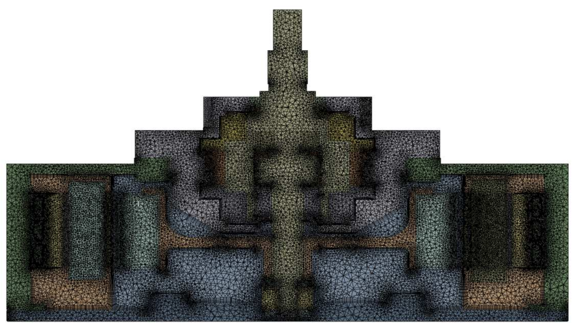
2. Numerical Analysis Method
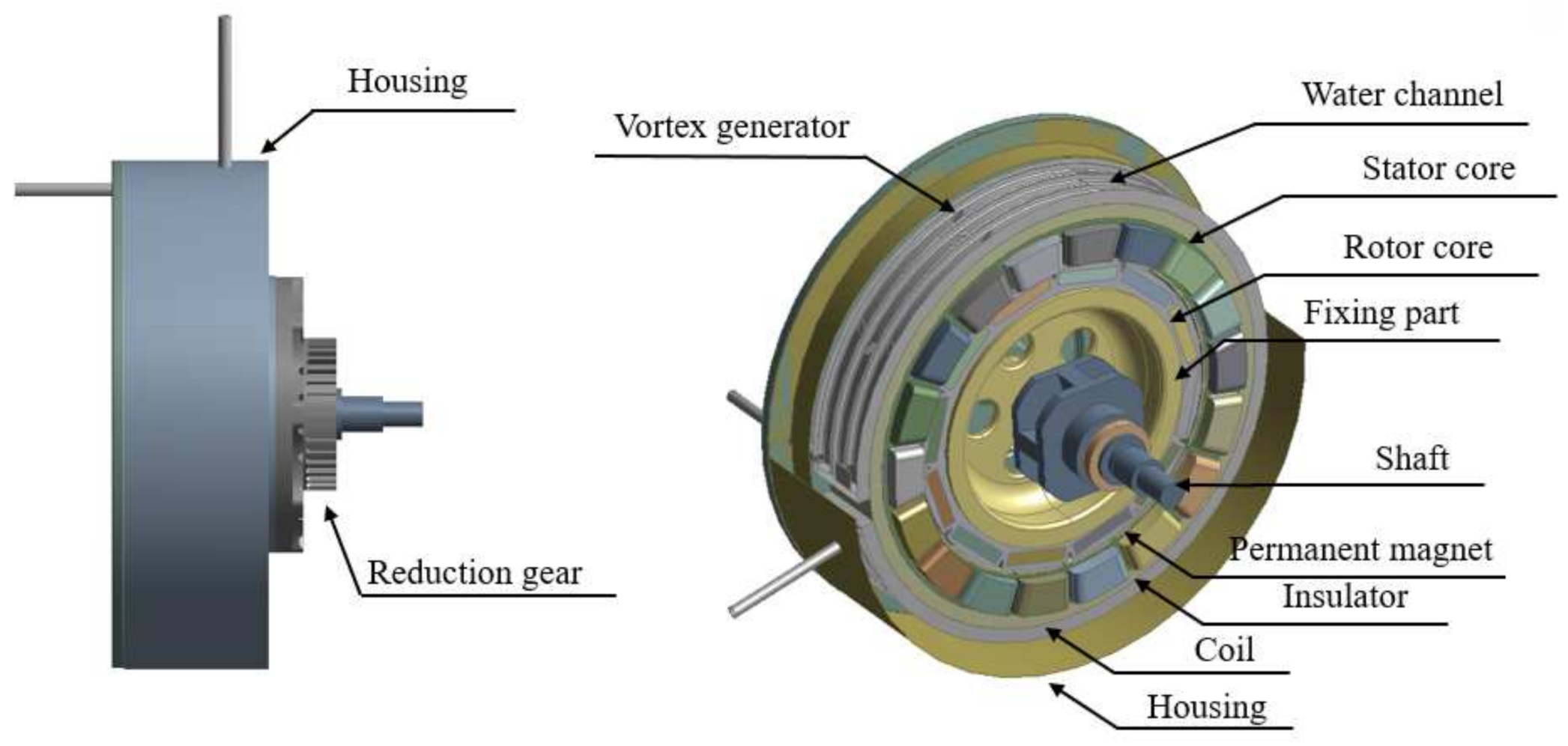
2.1. Physical Model
2.2. Mathematical Background
3. Results and Discussion
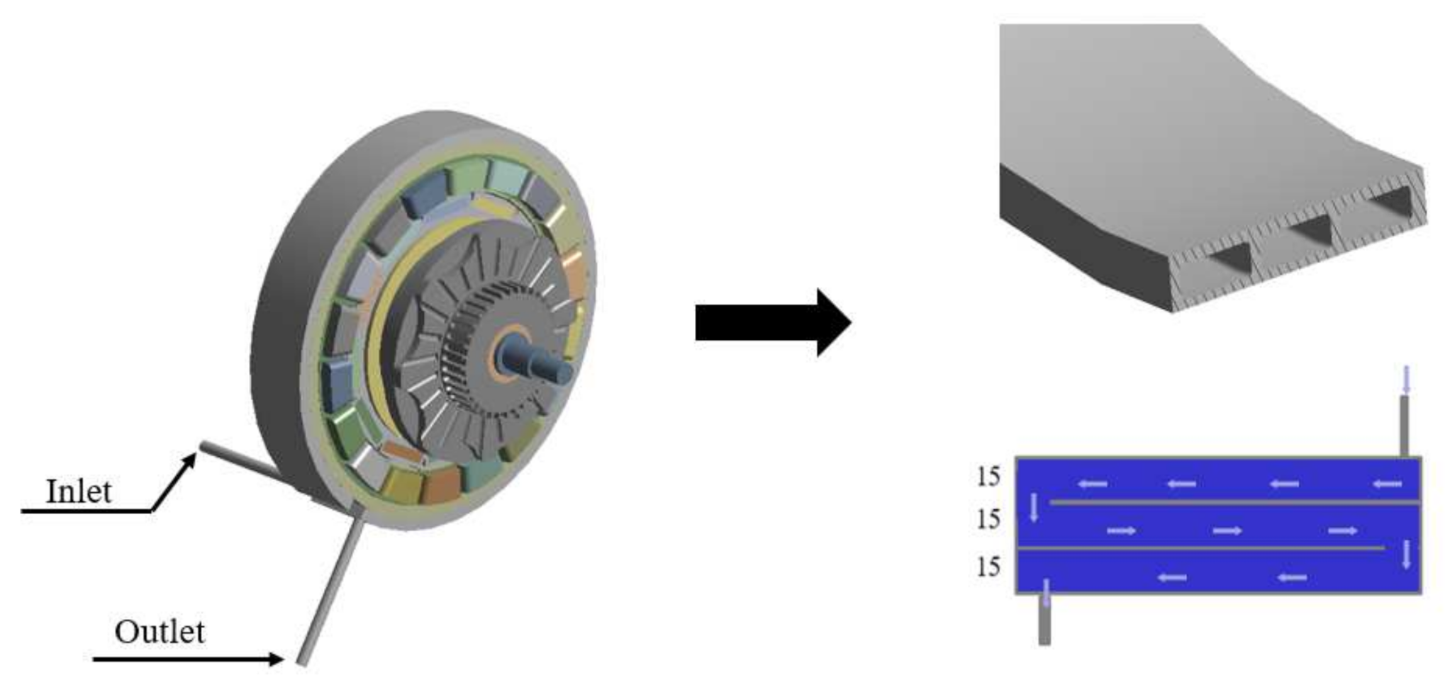
3.1. In-Wheel Motor with Simple Water Channel
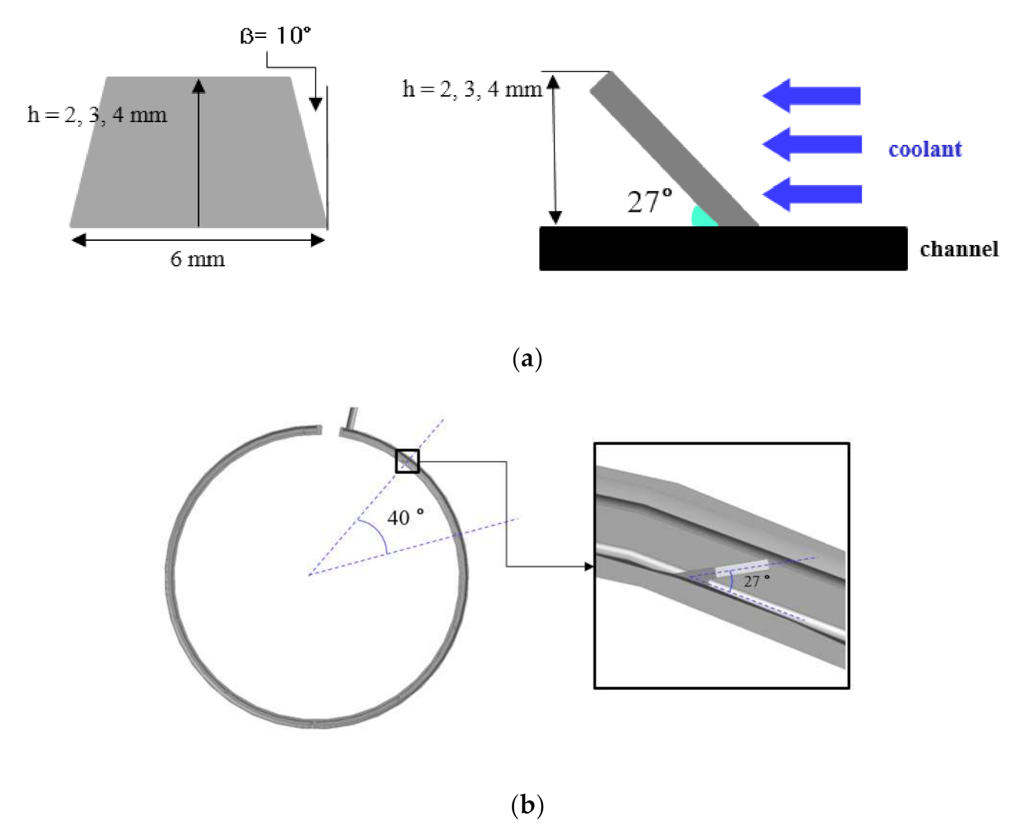
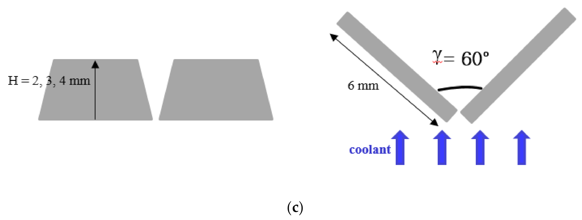
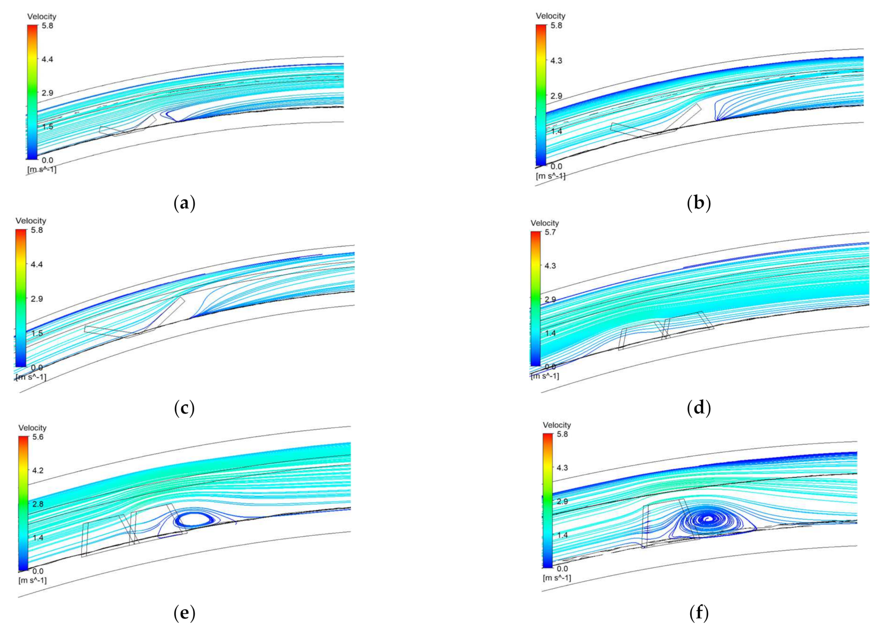
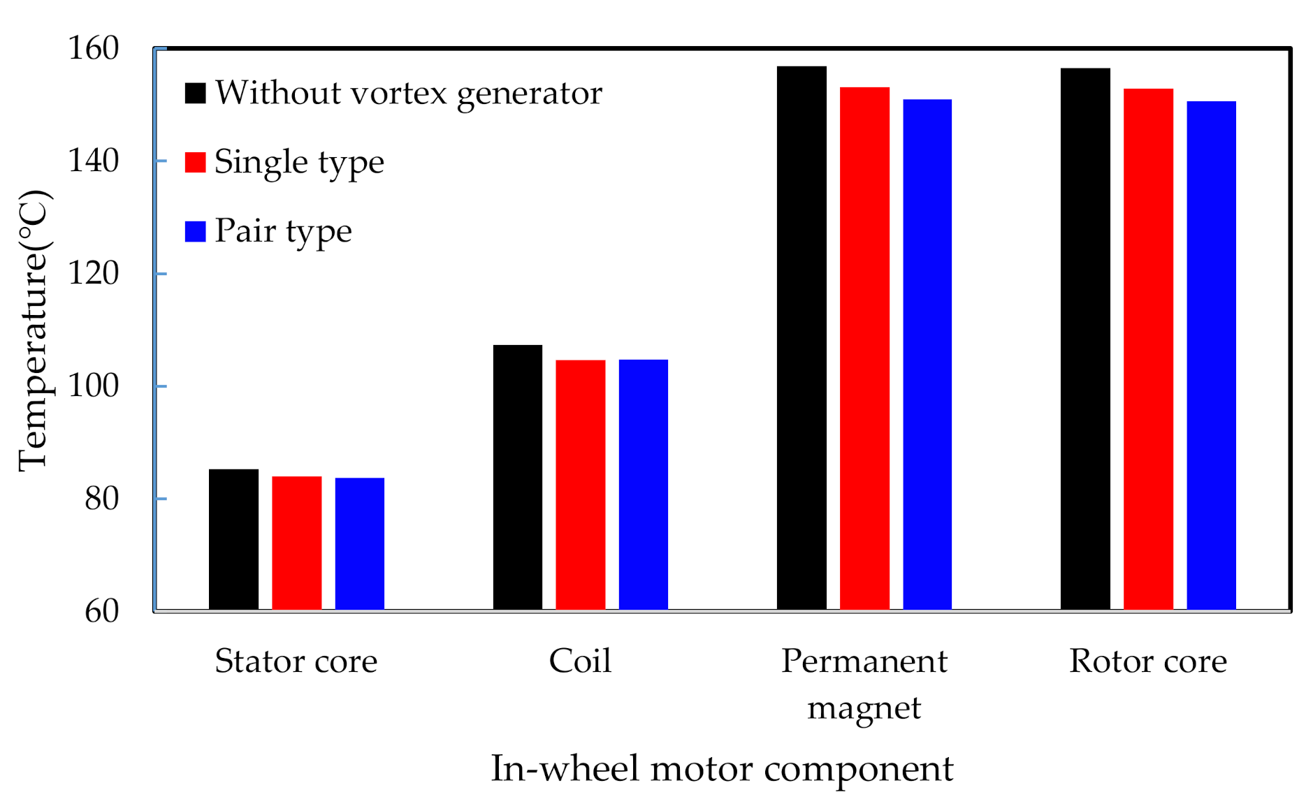
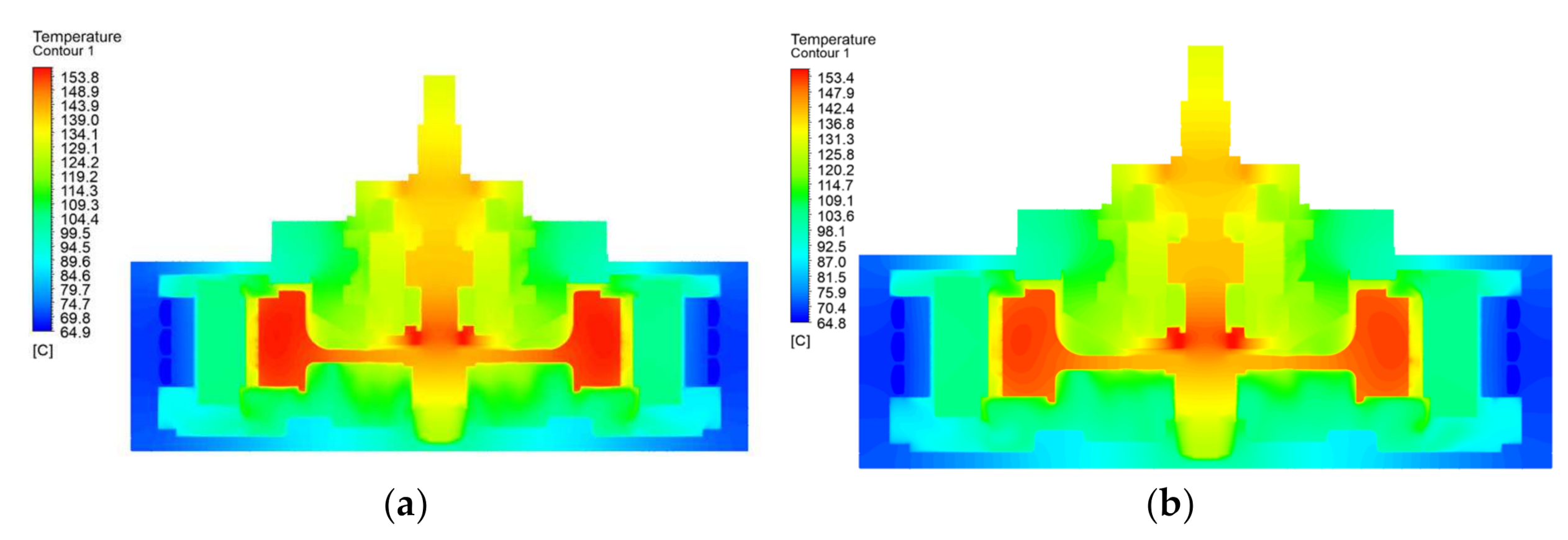
3.2. In-Wheel Motor with Enhanced Water Channels
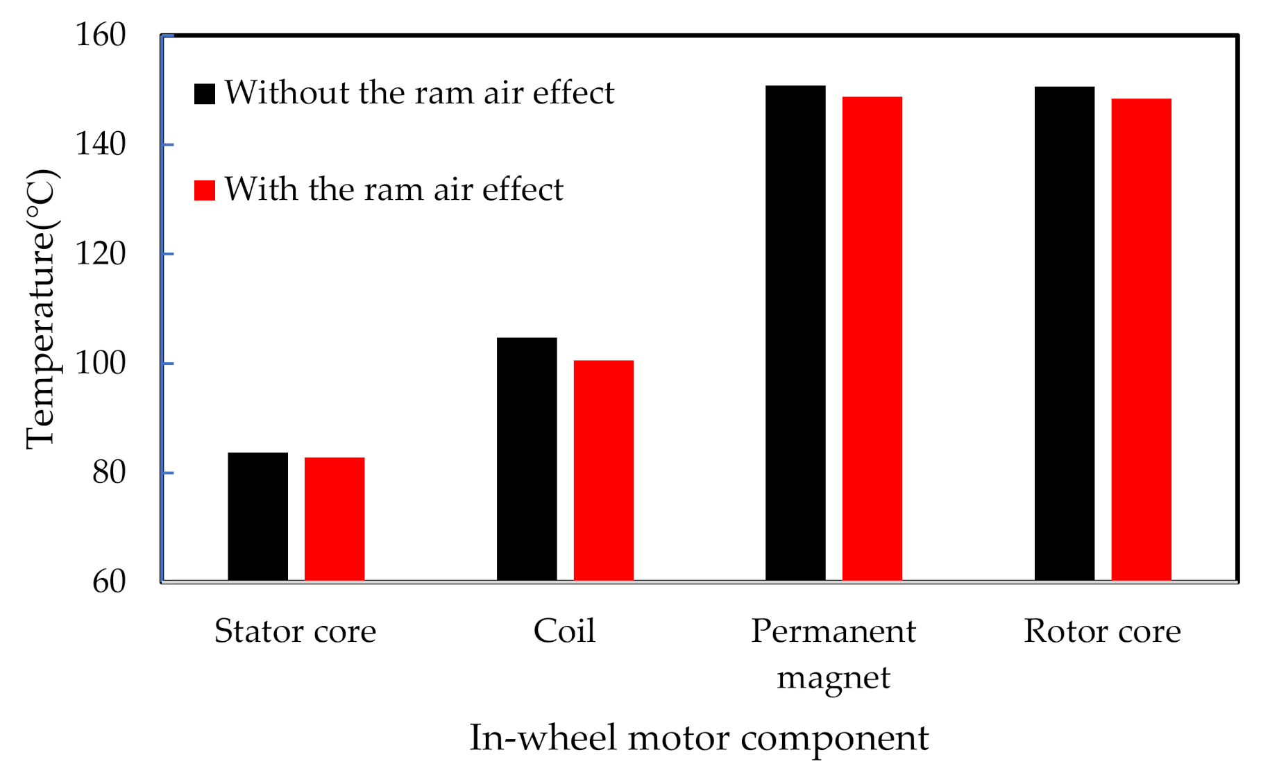
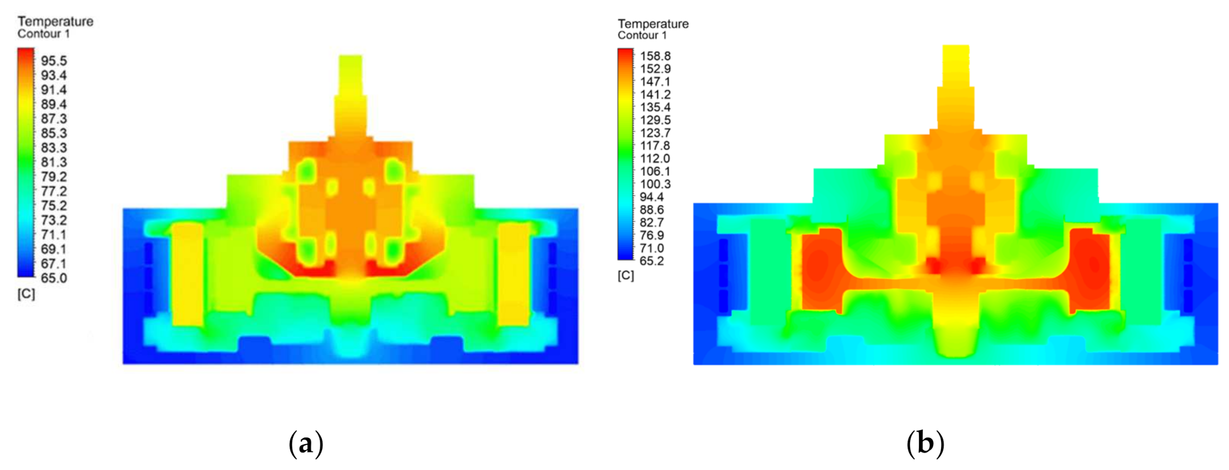
3.3. In-Wheel Motor Considering Ram Air Effect
4. Conclusions
Author Contributions
Funding
Institutional Review Board Statement
Informed Consent Statement
Data Availability Statement
Conflicts of Interest
Nomenclature
| k | Turbulent kinetic energy |
| ε | Turbulent dissipation rate |
| μ | Viscosity |
| ρ | Density of a fluid or a solid |
| t | Time |
| Velocity | |
| Distance | |
| Dynamic viscosity |
References
- Foley, A.; Tyther, B.; Calnan, P.; Gallachoir, B.O. Impacts of Electric Vehicle charging under electricity market operations. Appl. Energy 2013, 101, 93–102. [Google Scholar] [CrossRef]
- Mokashi, I.; Khan, S.A.; Abdullah, N.A.; Azami, M.H.; Afzal, A. Maximum temperature analysis in a Li-ion battery pack cooled by different fluids. J. Therm. Anal. Calorim. 2020, 141, 2555–2571. [Google Scholar] [CrossRef]
- Jilte, R.; Afzal, A.; Panchal, S. A novel battery thermal management system using nano-enhanced phase change materials. Energy 2020, 219, 119564. [Google Scholar] [CrossRef]
- Kim, D.; Shin, K.; Kim, Y.; Cheon, J. Integrated Design of In-Wheel Motor System on Rear Wheels for Small Electric Vehicle. World Electr. Veh. J. 2010, 4, 597–602. [Google Scholar] [CrossRef] [Green Version]
- Nie, S.; Zhuang, Y.; Chen, F.; Wang, Y.; Liu, S. A method to eliminate unsprung adverse effect of in-wheel motor-driven vehicles. J. Low Freq. Noise Vib. Act. Control. 2018, 37, 955–976. [Google Scholar] [CrossRef] [Green Version]
- Lu, S.; Xu, X.; Chen, L.; Wang, F.; Wang, W. Coordinated Control of Electronic Differential and Differential Assist Steering for Electric Vehicle Driven by In-Wheel Motors. Chin. J. Mech. Eng. 2017, 53, 78–85. [Google Scholar] [CrossRef]
- Kim, M.-S.; Lee, K.-S.; Um, S. Numerical investigation and optimization of the thermal performance of a brushless DC motor. Int. J. Heat Mass Transf. 2009, 52, 1589–1599. [Google Scholar] [CrossRef]
- Kim, S.C.; Kim, W.; Kim, M.S. Cooling performance of 25 kW in-wheel motor for electric vehicles. Int. J. Automot. Technol. 2013, 14, 559–567. [Google Scholar] [CrossRef]
- Park, M.H.; Kim, S.C. Thermal characteristics and effects of oil spray cooling on in-wheel motors in electric vehicles. Appl. Therm. Eng. 2019, 152, 582–593. [Google Scholar] [CrossRef]
- Chen, Q.; Shao, H.; Huang, J.; Sun, H.; Xie, E.J. Analysis of Temperature Field and Water Cooling of Outer Rotor In-Wheel Motor for Electric Vehicle. IEEE Access 2019, 7, 140142–140151. [Google Scholar] [CrossRef]
- Fasquelle, A.; Laloy, D. Water cold plates cooling in a permanent magnet synchronous motor. IEEE Trans. Ind. Appl. 2016, 53, 4406–4413. [Google Scholar] [CrossRef]
- Rehman, Z.; Seong, K. Three-D Numerical Thermal Analysis of Electric Motor with Cooling Jacket. Energies 2018, 11, 92. [Google Scholar] [CrossRef] [Green Version]
- Huang, Z.; Nategh, S.; Lassila, V.; Alakula, M.; Yuan, J. Direct oil cooling of traction motors in hybrid drives. In Proceedings of the 2012 IEEE International Electric Vehicle Conference, Greenville, SC, USA, 4–8 March 2012. [Google Scholar] [CrossRef]
- Li, J.; Lu, Y.; Cho, Y.-H.; Qu, R. Design an Analysis of a Water-Cooled Axial Flux Permanent-Magnet Machine for Large Power Direct-Driven Applications. In Proceedings of the 2018 XIII International Conference on Electrical Machines (ICEM), Alexandroupoli, Greece, 3–6 September 2018; pp. 118–124. [Google Scholar] [CrossRef]
- Satrústegui, M.; Martinez-Iturralde, M.; Ramos, J.C.; Gonzalez, P.; Astarbe, G.; Elosegui, I. Design criteria for water cooled systems of induction machines. Appl. Therm. Eng. 2017, 114, 1018–1028. [Google Scholar] [CrossRef]
- Deriszadeh, A.; de Monte, F.; Villani, M.; Di Leonardo, L. Hydrothermal Performance of Ethylene Glycol and Water Mixture in a Spiral Channel for Electric Motor Cooling. In Proceedings of the 2019 21st European Conference on Power Electronics and Applications (EPE 19 ECCE Europe), Genova, Italy, 3–5 September 2019. [Google Scholar] [CrossRef]
- Yang, C.; Wang, H.; Niu, X.; Zhang, J.; Yan, Y. Design and Analysis of Cycling Oil Cooling in Driving Motors for Electric Vehicle Application. In Proceedings of the 2016 IEEE Vehicle Power and Propulsion Conference (VPPC), Hangzhou, China, 17–20 October 2016; pp. 1–6. [Google Scholar] [CrossRef]
- Liang, P.; Chai, F.; Shen, K.; Liu, W. Thermal design and optimization of a water-cooling permanent magnet synchronous in-wheel motor. In Proceedings of the 2019 22nd International Conference on Electrical Machines and Systems (ICEMS), Harbin, China, 11–14 August 2019. [Google Scholar] [CrossRef]
- Choi, G. Analysis and Experimental Verification of the Demagnetization Vulnerability in Various PM Synchronous Machine Configurations for an EV Application. Energies 2021, 14, 5447. [Google Scholar] [CrossRef]
- Luo, L.; Chang, J.; Wu, J.; Zhu, B.; Zheng, M.; Zhang, N. Design and Analysis of a Water-Cooling System in a New Yokeless and Segmented Armature Axial In-Wheel Motor for Electric Vehicles. J. Therm. Sci. Eng. Appl. 2021, 13, 1–12. [Google Scholar] [CrossRef]
- Cuiping, L.; Zhengwei, G.; Junhui, L.; Bing, Z.; Xiucui, D. Optimal design of cooling system for water cooling motor used for mini electric vehicle. In Proceedings of the 2017 20th International Conference on Electrical Machines and Systems (ICEMS), Sydney, Australia, 11–14 August 2017; pp. 1–4. [Google Scholar] [CrossRef]
- Gretta, W.J.; Smith, C.R. The Flow Structure and Statistics of a Passive Mixing Tab. ASME J. Fluids Eng. 1993, 115, 255–263. [Google Scholar] [CrossRef]
- Kwon, B.; Liebenberg, L.; Jacobi, A.M.; King, W.P. Heat transfer enhancement of internal laminar flows using additively manufactured static mixers. Int. J. Heat Mass Transf. 2019, 137, 292–300. [Google Scholar] [CrossRef]
- Jiang, Y.; Chen, B.; Duan, C.; Yan, X.; Wang, L. Flow and heat transfer characteristics in square channel with concave–convex vortex generators based on numerical simulations. Asia-Pac. J. Chem. Eng. 2021, 16, e2601. [Google Scholar] [CrossRef]


| Parts | Density | Specific Heat | Thermal Conductivity |
|---|---|---|---|
| kg m−3 | J kg−1 K−1 | W m−1 K−1 | |
| Bearing | 7805 | 460 | 27 |
| Coil | 8900 | 376 | 388 |
| Housing | 2698 | 896 | 180 |
| Insulator | 1090 | 1840 | 0.41 |
| Permanent magnet | 7700 | 440 | 9 |
| Rotor core | 7600 | 4700 | 24 |
| Stator core | 7600 | 470 | 24 |
| Reduction gear | 7861 | 473 | 42.6 |
| Water channel | 2700 | 903 | 166.9 |
| Parameter | Value |
|---|---|
| Ambient temp. | 20 °C |
| Ambient heat transfer coefficient | 13 W m−2 k−1 |
| Coolant temp. | 65 °C |
| Flow rate of coolant | 7 LPM |
| Motor power | 25 kW |
| Motor speed | 1250 RPM, 5000 RPM |
| Speed | Iron Loss (W) | Copper Loss (W) | Eddy Current Loss (W) | Mechanical Loss(W) | Reduction Gear (W) | Torque (N-m) |
|---|---|---|---|---|---|---|
| 1250 RPM | 94.9 | 257.4 | 15.2 | 38.9 | 268 | 76.5 |
| 5000 RPM | 566.6 | 262.9 | 192.7 | 295.9 | 262 | 200 |
| Parts | Temperature (°C) | ||
|---|---|---|---|
| 1250 RPM | 5000 RPM | ||
| Housing | 69.4 | 75.7 | |
| Stator core | 73.7 | 85.3 | |
| Fixed parts | Coil | 90.2 | 107.3 |
| Insulator | 83.9 | 99.8 | |
| Reduction gear | 89.9 | 113.1 | |
| Shaft | 91.7 | 146.2 | |
| Rotating parts | Rotor core | 86.4 | 156.6 |
| Permanent magnet | 86.5 | 156.9 | |
| Parameter | Simple Model without Vortex Generator | Enhanced Model with Single-Type Vortex Generator | Enhanced Model with Pair-Type Vortex Generator |
|---|---|---|---|
| Water channel inner surface area (m2) | 0.0365 | 0.0380 | 0.0381 |
| Heat transfer coefficient at inner surface of coolant (Wm−2 k−1) | 6527 | 7125 | 8038 |
| Thermal performance (%) | - | 4.1 | 6.5 |
Publisher’s Note: MDPI stays neutral with regard to jurisdictional claims in published maps and institutional affiliations. |
© 2022 by the authors. Licensee MDPI, Basel, Switzerland. This article is an open access article distributed under the terms and conditions of the Creative Commons Attribution (CC BY) license (https://creativecommons.org/licenses/by/4.0/).
Share and Cite
Bae, J.C.; Cho, H.R.; Yadav, S.; Kim, S.C. Cooling Effect of Water Channel with Vortex Generators on In-Wheel Driving Motors in Electric Vehicles. Energies 2022, 15, 722. https://doi.org/10.3390/en15030722
Bae JC, Cho HR, Yadav S, Kim SC. Cooling Effect of Water Channel with Vortex Generators on In-Wheel Driving Motors in Electric Vehicles. Energies. 2022; 15(3):722. https://doi.org/10.3390/en15030722
Chicago/Turabian StyleBae, Jae Chang, Hyeon Rae Cho, Saurabh Yadav, and Sung Chul Kim. 2022. "Cooling Effect of Water Channel with Vortex Generators on In-Wheel Driving Motors in Electric Vehicles" Energies 15, no. 3: 722. https://doi.org/10.3390/en15030722
APA StyleBae, J. C., Cho, H. R., Yadav, S., & Kim, S. C. (2022). Cooling Effect of Water Channel with Vortex Generators on In-Wheel Driving Motors in Electric Vehicles. Energies, 15(3), 722. https://doi.org/10.3390/en15030722