Abstract
The switched reluctance motor (SRM) has many merits, such as robustness, a simple construction, low cost, and no permanent magnets. However, its deployment in servo applications is restrained due to acoustic noise and torque ripple (TR). This paper presents a new torque control approach for TR reduction in switched reluctance drives. The approach is based on the maximum utilisation of the available dc-link voltage, hence extending the zero torque-ripple speed range. The approach is suitable for an SRM with any number of phases and stator/rotor poles. Soft switching control is deployed, which reduces switching losses. At any instant (regardless of the number of phases being conducted simultaneously), only one phase current is controlled. The well-established torque-sharing function concept is adapted and generalised to cater for more than two phases conducting simultaneously. MATLAB/Simulink confirmation simulations are based on the widely studied four-phase 8/6, 4 kW, 1500 rpm SRM.
1. Introduction
Although the switched reluctance motor (SRM) has many merits, such as robustness, a simple construction, low cost, and no permanent magnets, hence higher operating temperature limits [1,2], its deployment in servo applications is restrained due to the following: firstly, acoustic noise caused by radial vibration [3]; secondly, severe torque ripple (TR) during commutation (the transfer of torque production from an outgoing phase to an incoming phase) due to the discrete and non-linear nature of SRM torque production [4]; and thirdly, non-standard bridge converter configuration [5,6]. The high torque ripple may cause mechanical vibration stresses (possibly resulting in mechanical resonance effects) and speed oscillation at low speeds, which are undesirable in applications such as an electric vehicle (EV) [7]. Many solutions have been proposed to alleviate the first two undesirable SRM features [8]. Generally, two main approaches are available to reduce TR, namely the motor design approach and the control approach [9].
Increasing the number of SRM stator and rotor poles results in an overlap of more than two phases during commutation, which can minimise torque ripple. However, the increased switching frequency results in more converter losses and machine losses. In addition, extra converter switches are required (if the number of phases increases), increasing the converter cost [10].
A new SRM approach explores an SRM with a higher number of rotor poles than stator poles, as presented in [11]. The new motor concept has a lower mass and copper loss than the conventional SRM. Due to the extra space available in the stator slot area, windings with a higher number of turns and thicker cross-sectional area can be deployed [12]. Also, the increased rotor pole number minimises TR, which is vital for EV application [13]. However, since the interpolar rotor air gaps are narrower in the new motor design, the unaligned inductance is significantly higher than that of the conventional SRM. The increase in unaligned inductance reduces the energy conversion area and thus decreases the developed torque [14]. Also, the current rise time at phase turn-on is prolonged as a consequence of higher unaligned inductance, which implies using higher dc-link voltages to increase the current rate of rise [15]. Introducing a notch in the rotor pole was presented in [16] for TR reduction. This approach was extended in [17] for a mutually coupled SRM. The rotor pole shoe is discussed in [18]. On the other hand, a stator pole slant is demonstrated in [19], and a non-uniform air gap for a two-phase SRM is presented in [20]. All these variations attempt to minimise TR. However, the machine torque density is reduced. Increasing the average torque and reducing torque ripple was proposed in [21] by optimising the stator and rotor poles for a four-phase 8/6 SRM. However, the approach of modifying the machine design is limited to a narrow speed range and for rated load conditions. Moreover, changes to the basic rotor/stator design result in a reduced power output, which is an unacceptable SRM limitation in EVs.
As opposed to the machine design approach, the control approach is less expensive, more effective and flexible, and can cover a wide range of speeds [22]. Ripple-free torque could be obtained by current profiling [23], where optimal current contours, producing constant output torque, are generated using static SRM data. These current profiles are stored using look-up tables (LUTs), and current controllers are used to track these profiles [24]. A high bandwidth current controller is used to accurately track the stored current profiles [25,26,27]. Using conventional pulse-width modulation (PWM) may result in current tracking errors, especially at high speeds [28,29,30,31,32]. In [33,34], current profiling along with a new SRM design with a flat torque profile are combined to reduce the torque ripple. Yet, the new machine design has a narrow speed range compared with conventional SRM designs.
Generally, optimal current profiles are generated as discrete points, and the intermediate points are found using linear interpolation. Increasing the number of points will improve the accuracy at the expense of time and storage memory in the form of LUTs. In [35], harmonic coefficients are used to produce the required current profiles, where interpolation is not required. However, this method is based on the accuracy of the analytical model. Fuzzy logic and neural networks presented in [36,37] can generate the required magnetisation data without the need for a huge memory. However, the computational complexity increases significantly. In [38,39], a control scheme is developed based on iterative learning control. The advantage of this method is that it does not depend on model accuracy and does not need a large memory to store the magnetisation data. Yet, it has slow dynamics with a poor response during transients, which is not tolerable in EV applications.
Average torque control (ATC) was presented in [40,41], where torque is calculated using co-energy that is derived based on terminal quantities (voltage and current) [42]. The method is extended in [43] for four-quadrant operation at low speeds. However, this method relies on high-precision measurements of voltage and current. In addition, the effect of varying the stator resistance (due to temperature change) is not considered, which affects the co-energy estimation.
The principle of direct torque control (DTC), which is similar to that used for induction motors, was proposed in [44] and optimised in [45]. The concept is based on controlling the flux, which, in turn, controls the developed torque [46]. Improving the torque per ampere ratio and, hence, improving the efficiency, was considered in [47,48]. A model predictive controller was presented in [49] to choose the suitable voltage vector. However, the method relies on the SRM mathematical model, which does not reflect machine non-linearity.
Direct instantaneous torque control (DITC) can continuously control the instantaneous value of developed torque [50], so it significantly minimises TR. In [51], a four-quadrant DITC was presented, while [52] presented an extension of the method for SRMs with more than four phases. However, this method requires a complicated algorithm [53]. In addition, there is no current control, which poses a limitation for SRM operation with one failure phase [54].
Among different control approaches, torque-sharing functions (TSFs) reliably reduce the TR generated during commutation. In [55], the objective was to optimise linear and sinusoidal TSFs in order to reduce the TR along with the phase rms current. However, saturation was neglected, and analytical expressions were required within the optimisation process. In [56], the concept of the maximum rate of change of flux linkage was introduced to assess conventional TSFs (linear, sinusoidal, cubic, and exponential). It was shown that a low rate of change of flux linkage increases the ripple-free speed range. Additionally, optimal values for turn-on and overlap angles were advised. A logical non-linear TSF was proposed in [57], with no attention to the maximum rate of change of flux linkage. In [58], an online TSF was proposed, where the selection between commutating phases is based on the rate of change of flux linkage. Nevertheless, this method requires a PI controller to compensate for the error between the reference and estimated torque. Also, the conversion of torque expression to current expression requires analytical formulation. An offline TSF was presented in [59], which offers a trade-off between a low rms current and low rate of change of flux linkage. The model requires accurate analytical expressions to derive the current profiles. A DITC-based TSF was proposed in [60], which requires fewer current sensors. However, the phase current detection accuracy is low. Also, circuit modification along with two high-frequency PWM signals are required for phase current extraction. A hybrid switching mode (a combination between hard and soft switching) was proposed in [61] instead of the hard switching mode usually adopted in conventional TSFs. However, there was no illustration of the maximum ripple-free speed range of this method. In [62], an off-line TSF based on a SRM’s magnetic characteristics is proposed, where a weighting parameter is adjusted to minimise the rms current while ensuring that the rate of change of flux linkage is below the dc-link voltage for accurate current tracking. However, the dc-link voltage is not fully utilised. Hence, the zero TR speed ranges are limited.
In the literature, all TSFs have some salient shortcomings, which can be summarised as follows:
- All TSFs are limited to one or two phases conducting simultaneously. There has been no attempt to investigate TSF performance for more than two phases conducting simultaneously.
- The dc-link voltage was not fully exploited, which limits the ripple-free speed range.
- Either hard or hybrid switching is required for accurate current tracking, which increases switching losses.
- The turn-on angle cannot be advanced beyond the unaligned position for rapid current buildup.
Reference [63] proposed a new torque control function for TR minimisation, extending the zero TR speed range by fully utilising the dc-link voltage. A ripple-free operation was possible up to 71% of the base speed, which is still far below the SRM base speed. In addition, there was no attention to the rms current and, hence, the SRM efficiency. Moreover, the method only allows for two-phase overlap.
This paper presents a torque control function (TCF, as opposed to TSF, since torque will be controlled by controlling one phase only) based on an SRM’s magnetic characteristics. The new TR analysis concept separates TR into two independent components, namely phase commutation torque ripple and switching (PWM/hysteresis) torque ripple.
The merits of the proposed TCF are as follows:
- The method is suitable for an SRM with any number of phases and stator/rotor poles.
- The concept of TSF is generalised to include more than two phases conducting simultaneously.
- Maximum utilisation of available dc-link voltage is achieved at turn-on and turn-off, with no switching, hence reducing switching losses and increasing the ripple-free speed range.
- The SRM maximum speed range with theoretically zero TR (commutation ripple elimination, leaving ripple due to PWM switching only) is determined.
- Soft switching control is deployed (as opposed to hard or hybrid switching as usually adopted for traditional TSFs), which reduces switching losses.
- The proposed TCF requires switching for a period equal to the stroke angle only instead of the full conduction period, which reduces switching losses.
- At any instant (regardless of the number of phases conducting simultaneously), only one phase current is controlled, hence termed torque control function, TCF. Effects due to phase coupling, short/long flux paths, saturation, Cu temperature, etc., can be compensated by adjusting the single controlling current.
The paper is organised as follows: Section 2 presents the new TCF with the proposed control technique. Section 3 investigates the maximum torque ripple-free speed range achieved at different torque demands using the proposed TCF. The proposed method is validated by simulations in Section 4. Section 5 discusses the effect of varying the turn-on angle for rms/peak current reduction and compares the proposed TCF against other TR-minimisation methods. Conclusions form Section 6.
2. Proposed Torque Control Function
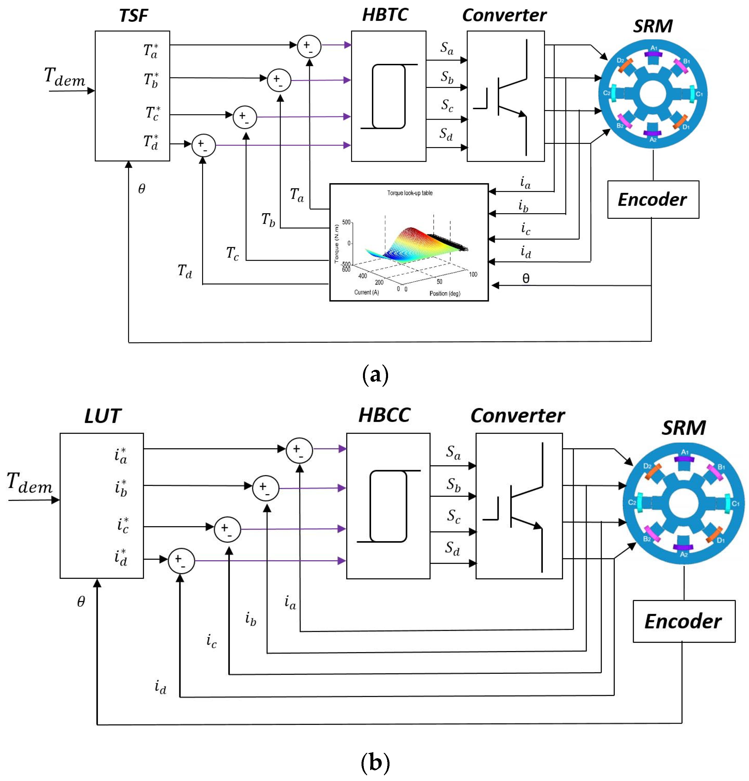
The proposed TCF for commutation ripple reduction generates a flux linkage profile that fully utilises the dc-link voltage at both turn-on and turn-off. This flux profile is transformed to a current profile stored in a (3D finite element-based) look-up table (LUT). Figure 1 shows the block diagram of the conventional TSF and the proposed TCF. In the former, the total torque demand is used to generate the reference phase torques. Actual phase currents are transformed into phase torques using LUTs. A hysteresis band controller (HBC) compares the reference and actual phase torques to generate the gating signals. On the other hand, the proposed TCF generates the required reference current profiles depending on the motor speed and the torque demand. Actual phase currents are compared with reference currents, and an HBC generates the required driving signals.
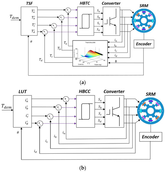
Figure 1.
Block diagram: (a) conventional TSF and (b) proposed TCF.
A 4φ, an 8/6 SRM, with specifications given in Table 1 and finite element analysis data in Appendix A, is selected to demonstrate the proposed TCF, noting that the proposed method is suitable to any SRM. The rotor pole pitch and the phase shift for an 8/6 SRM are and , respectively. For the SRM under study, the unaligned position is at , while the aligned position is at (negative torque to ; positive torque to ). All the angles are mechanical degrees.

Table 1.
SRM specifications (4 kW at 1500 rpm, 25 Nm).
The SRM is driven by a conventional asymmetric half-bridge converter (ASHB) with two switches and two diodes per phase. Three voltage states are available for the operation of the converter, namely magnetisation, freewheeling, and de-magnetisation states.
Magnetisation, , is where the full dc-link voltage is applied on the phase; thus, the current builds up quickly, reaching the reference value.
Freewheeling,, is where zero voltage is applied across the phase winding to regulate the current. Hence, the current is maintained within the reference value.
De-magnetisation,, is where the full negative dc-link voltage is applied on the phase. The de-magnetisation energy via the motor winding is pumped back to the dc link, reducing the winding current to zero before the SRM enters the negative torque-production region.
Figure 2 shows the typical voltage and current waveforms for the three states, illustrating the switching and conduction periods.
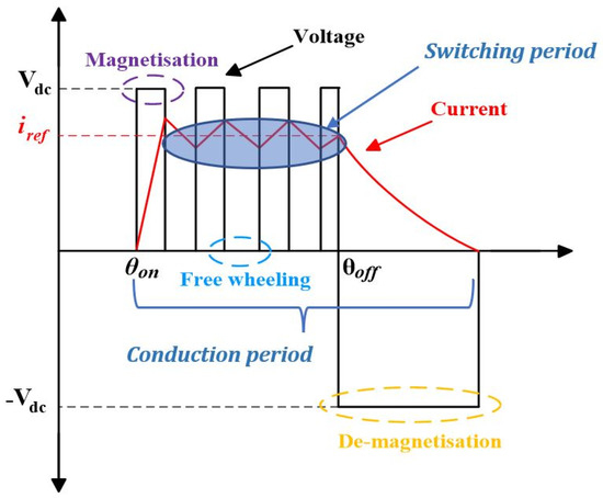
Figure 2.
Typical voltage and current waveforms using ASHB.
For the proposed TCF, two modes of SRM operation exist:
- Mode #1: phase current conduction ≤ 30° (single- or two-phase simultaneous conduction);
- Mode #2: phase current conduction > 30° (two- or three-phase simultaneous conduction).
These two modes of operation are investigated in the following subsections.
2.1. Mode #1 (Phase Current Conduction ≤ 30°)
In this mode of operation, either one or two phases (simultaneously) conduct to generate the required torque. The maximum conduction period for each phase is limited, in this mode, to . Figure 3 shows the phase torques and total torque for an arbitrary conduction period, .
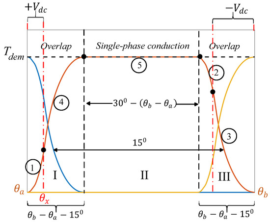
Figure 3.
Illustration of the proposed TCF in mode #1.
In regions I and III, two phases overlap and additively produce the demanded torque, while in region II, only one phase produces the required torque. If the conduction period is (that is, and ), the second region (II) vanishes, and only regions I and III exist.
The goal is to generate a phase torque profile, which fully utilises the available dc-link voltage and, in so doing, will offer the widest zero TR speed range. The phase torque profile will be composed of five parts. To illustrate the concept, a numerical example is given with and .
When the incoming phase is at 35°, a full positive dc-link voltage, +, is applied continuously (no switching) to this phase for rapid current and, hence, torque buildup, producing portion 1 (in this case, the incoming phase is termed the master phase). Simultaneously, the outgoing phase is at 50° (due to a 15° phase shift). The outgoing phase generates the rest of the torque so that the torque demand level is reached. Hence, portion 2 is determined (in this case, the outgoing phase is termed the control phase).
When angle is reached, the outgoing phase takes precedence. Hence, the outgoing phase becomes the master phase, and a full negative dc-link voltage, −, is applied continuously (no switching) for rapid current extinction, resulting in portion 3. Simultaneously, the incoming phase becomes the control phase supplying the torque deficiency to maintain the torque demand. Hence, portion 4 is specified. Finally, portion 5, region II, is when only one phase conducts to generate the demanded torque. Concatenating the five portions, the phase torque profile is obtained.
Table 2 demonstrates this process in the overlap region (the single-phase conduction region, portion 5, is excluded).
Table 2.
Illustration of the proposed TCF during phase overlap.
The final step is to calculate the value of which maximises the zero TR speed, ().
Equation (1) defines the voltage equation at turn-on/off for one SRM phase, neglecting phase-winding resistance.
Here, λ is the flux linkage. + is applied continuously at phase turn-on (portion 1), while − is applied continuously at phase turn-off (portion 3).
Integrating (1):
where , are the final and initial values of flux linkage, respectively, while t is time.
At phase turn-on, the initial flux linkage of the phase winding is zero. Hence, the final flux linkage is calculated by:
At phase turn-off, the flux linkage must decay to zero before/at the aligned position (to avoid entering the negative torque-production region). Hence, the final flux linkage is zero, and the initial flux linkage is calculated from:
Equations (3) and (4) are solved to calculate and ensuring that (5) is satisfied.
For the numerical example with a torque demand of 25 Nm, the angle is 36.65°, is 355 rpm, is 0.32 Wb-t, and is 0.65 Wb-t. The developed phase torques for the incoming and outgoing phases are 10.35 Nm and 14.65 Nm, respectively, and the rms phase current is 11.63 A.
Figure 4 shows the flowchart, which describes the operation steps in model #1.
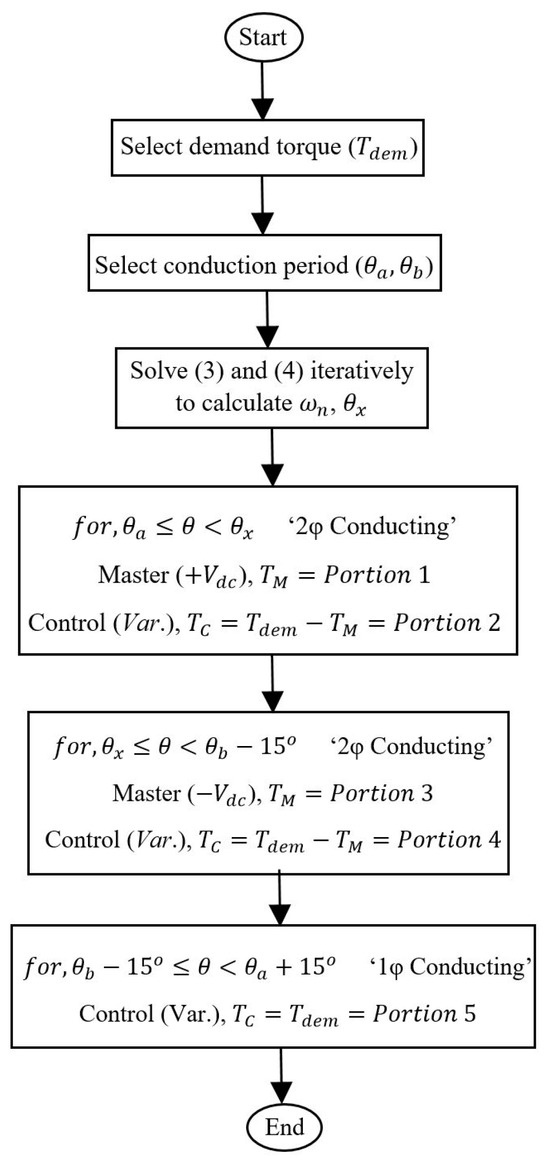
Figure 4.
Flowchart of the proposed TCF in mode #1.
2.2. Mode #2 (Phase Current Conduction > 30°)
Figure 5 shows the operation in mode #2, where two/three phases conduct simultaneously to produce the required torque.
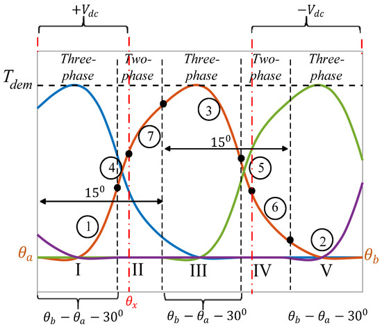
Figure 5.
Illustration of the proposed TCF in mode #2.
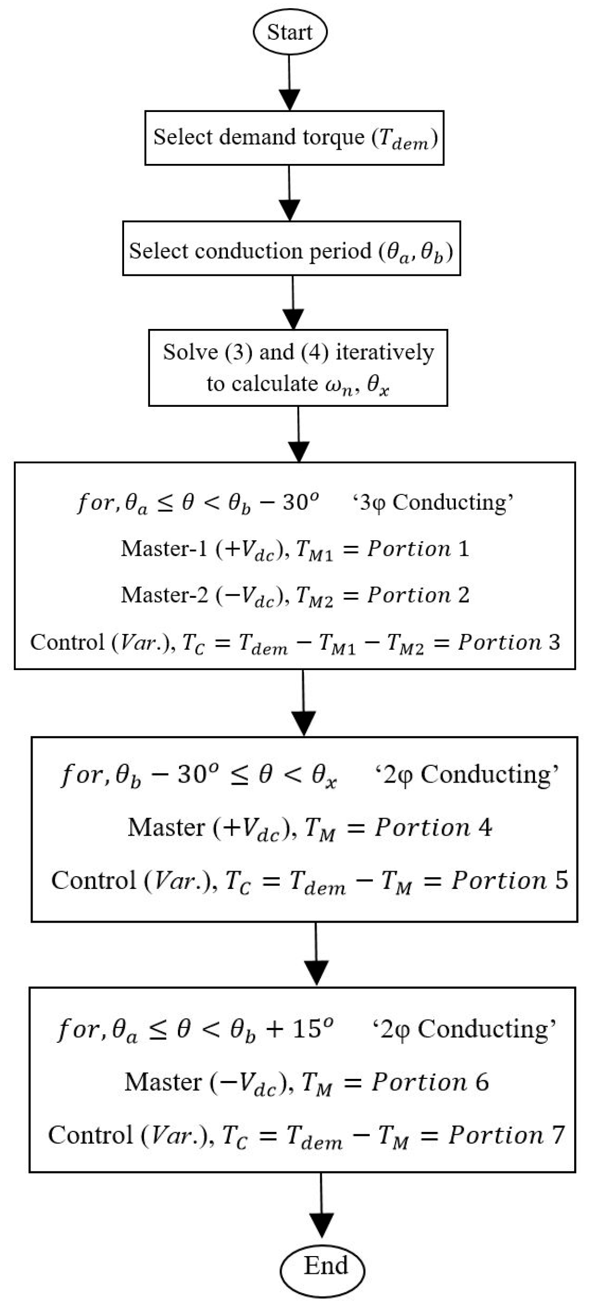
In the three-phase conduction region, there are two master phases and one control phase. A full dc-link voltage, +Vdc, is applied continuously on the incoming phase (Master #1), giving portion 1, and a full negative dc voltage, −Vdc, is applied continuously on the outgoing phase (Master #2), giving portion 2. Meanwhile, the middle phase is the control phase, which supplies the rest of the demand torque, producing portion 3.
The two-phase conduction period provides the remaining portions (4, 5, 6, and 7), as specified in mode #1.
For the numerical example with a torque demand of 25 Nm, the angle is , is 1765 rpm, is 0.39 Wb-t, and is 0.58 Wb-t. The developed phase torques for the incoming and outgoing phases are 11.1 Nm and 13.9 Nm, respectively, and the rms phase current is 14.1 A.
Figure 6 shows the flowchart, which describes the operation steps in model #2.
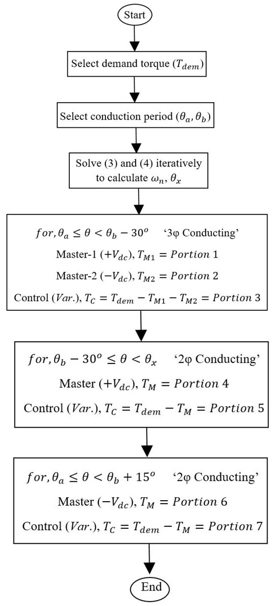
Figure 6.
Flowchart of the proposed TCF in mode #2.
3. Zero TR Speed Range of the Proposed TCF
This section investigates the maximum torque ripple-free speed range achieved at different torque demands using the proposed TCF in modes #1 and #2.
The maximum speed range with zero TR is calculated for 25%, 50%, 75%, and 100% full-load torque (FLT) for the two modes.
3.1. Mode #1 (Phase Current Conduction ≤ 30°)
The maximum conduction period for each phase in mode #1 is 30°. The corresponding maximum ripple-free speed at FLT is 1065 rpm. The SRM’s performance is illustrated in Figure 7. The flux linkage profile is shown in Figure 7a, which is linear near the unaligned and aligned positions.
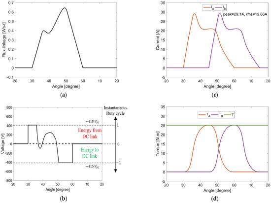
Figure 7.
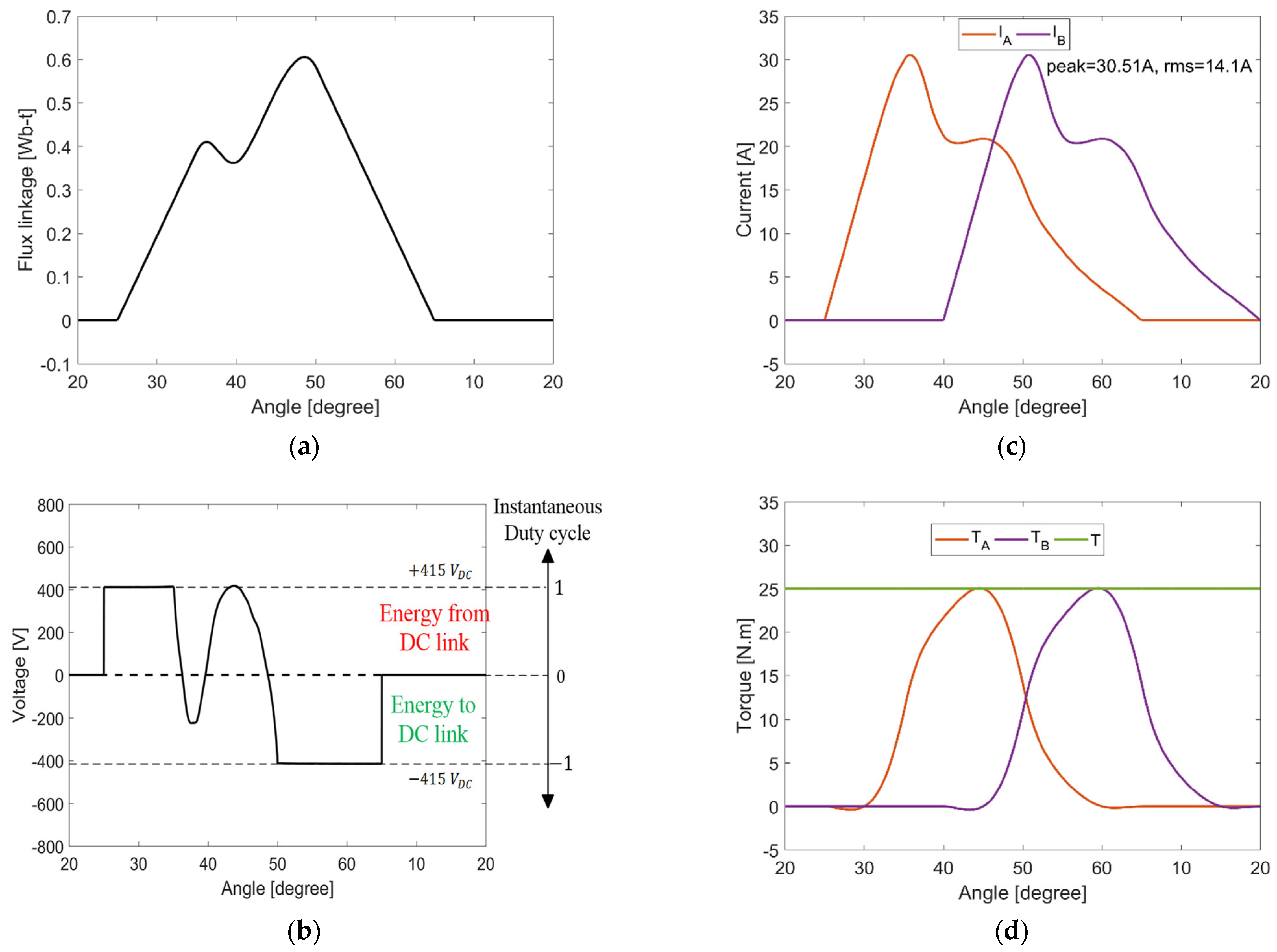
SRM performance at FLT and 1065 rpm using proposed TCF in mode #1: (a) flux linkage waveform, (b) rate of change of flux linkage (voltage demand), (c) current waveforms, and (d) torque waveforms.
This is expected, as the full dc-link voltage, either positive or negative, is applied (continuously) on the phase winding at turn-on and turn-off, respectively, as highlighted in Figure 7b, where the voltage profile is the derivative of flux linkage with respect to time (). The required current profiles are demonstrated in Figure 7c. Finally, torque waveforms are plotted in Figure 7d, which show zero TR operation.
The maximum speed, rms, and peak currents are calculated for different torque demands, namely 25%, 50%, 75%, and 100% FLT. The results are summarised in Table 3.
Table 3.
TCF Performance, mode #1, at different torque demands.
The proposed TCF extends the zero TR speed range at different torque demands. Hence, with an FLT base speed of 1500 rpm, 1065 rpm means that 71% of the FLT speed range can be torque ripple-free.
3.2. Mode #2 (Phase Current Conduction > 30°)
To further exploit the proposed TCF, the conduction period can be extended beyond 30°, thereby introducing negative torque production (but in low Nm/A regions). With an increased conduction period, an increased rms current can be expected.
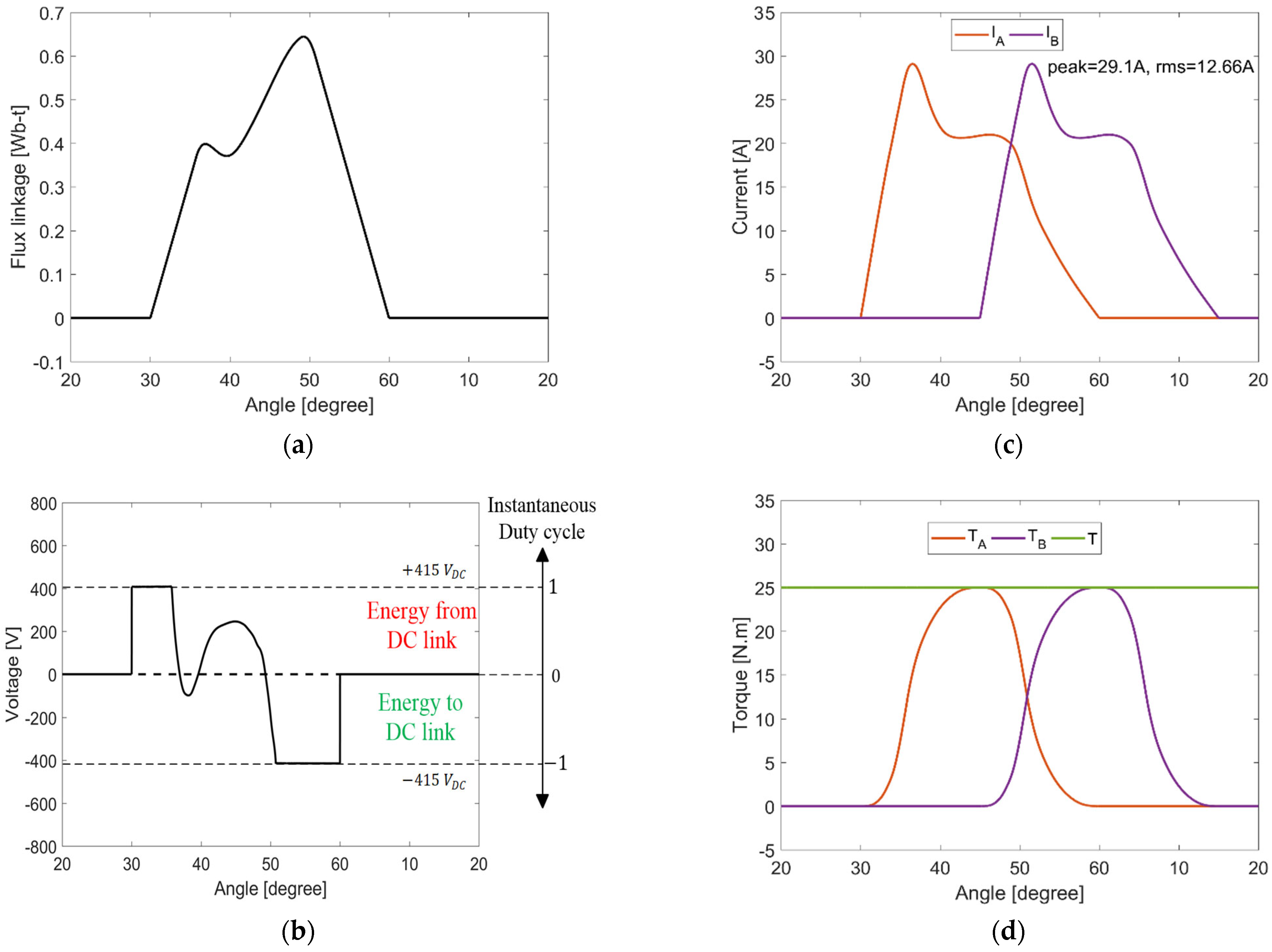
Figure 8 shows the SRM performance at FLT and 1765 rpm (representing an 18% increase in the output power, hence the machine rating). The conduction period is extended to 40°. Figure 8a shows the flux linkage waveform, while Figure 8b shows the voltage demand (rate of change of flux linkage). The voltage demand in the control period reaches the dc-link value, indicating that further improvements in the speed range with zero TR are not possible unless a higher dc-link voltage is utilised. Due to the conduction period extension (and negative torque portions), the rms current increases to 14.1 A (commensurate with increased power), as illustrated in Figure 8c.
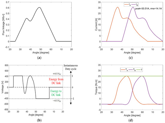
Figure 8.
SRM performance at FLT and 1765 rpm using proposed TCF in mode #2: (a) flux linkage waveform, (b) rate of change of flux linkage (voltage demand), (c) current waveforms, and (d) torque waveforms.
Since each phase conducts beyond the unaligned/aligned positions, a small negative torque is produced in low Nm/A regions, as demonstrated in Figure 8d. Since the currents are low and the Nm/A is also low around the unaligned/aligned positions, the operation is ripple-free.
The maximum speed, rms, and peak currents are calculated for different torque demands, namely 25%, 50%, 75%, and 100% FLT. The results are summarised in Table 4, wherein the zero TR speed range is increased to 1765 rpm (118% base speed) with an increased rms current due to the 18% power output increase.
Table 4.
TCF performance, mode #2, at different torque demands.
When the SRM operates at low speeds, the dc-link voltage does not pose any limitation on the SRM’s ripple-free operation. Hence, it is necessary to use a current profile with a low rms current. Figure 9 shows different current profiles for different zero TR speed ranges, where each current profile satisfies specific, discrete FLT operating speeds. Importantly, as the speed decreases, the conduction period decreases toward independent 15° periods, as the master periods (±Vdc) reduce to zero and the control period dominates.
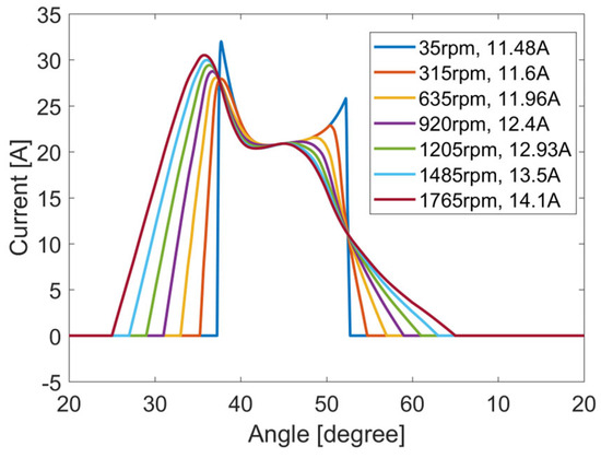
Figure 9.
Current profiles at FLT and different speed limits.
4. Simulation Results
In the previous sections, a TCF was proposed, which eliminates TR during phase commutation. The results were produced using an ideal current source (no semiconductor switching), where the current source terminal voltage indicated the switch state duty cycle. However, when tracking the generated current profiles (that produce zero commutation TR) with a voltage source converter, another form of TR appears due to switching, which produces current ripple (hence torque ripple, which will be termed switching as opposed to commutation ).
In this section, the SRM’s dynamic performance using the proposed TCF is investigated, and the effect of voltage switching (current ripple) on the generated TR is discussed. The current is sampled at 200 kHz, and the hysteresis band is 0.3 A (specification parameters well within the bounds of fluxgate current measurement technology). It is worth mentioning that the paper separates between commutation and switching TR and proposes a method to fully eliminate commutation TR. Switching TR is inevitable and present in all the TR-minimisation approaches available in the literature.
4.1. Mode #1 (Phase Current Conduction ≤ 30°)
In this subsection, the results of the proposed TCF are presented at FLT and 1065 rpm (the zero TR speed limit), as illustrated in Figure 10. The phase conduction period is 30°.
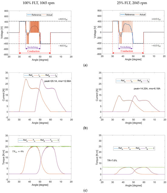
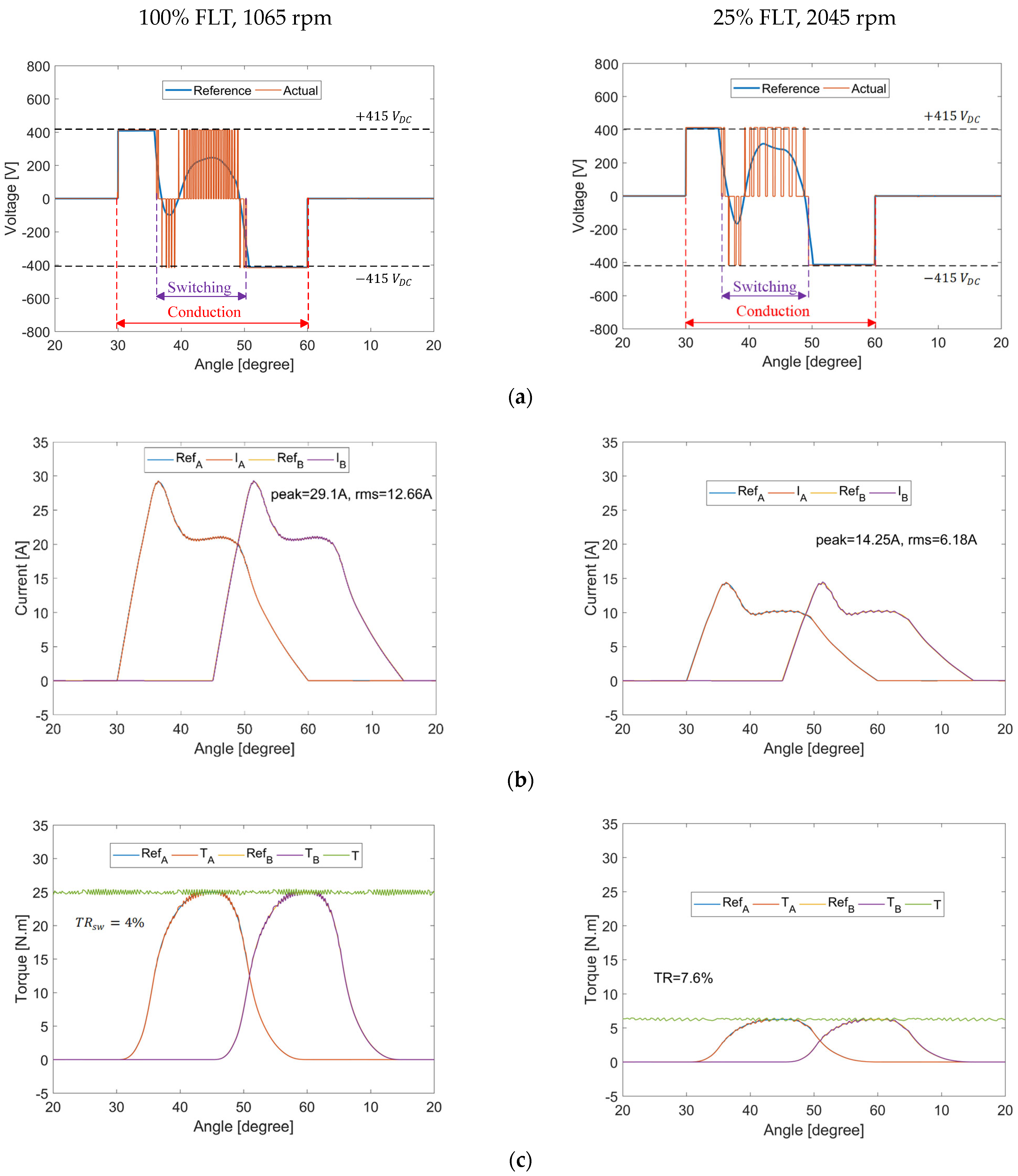
Figure 10.
SRM performance at 100% FLT and 1065 rpm and 25% FLT and 2045 rpm using TCF mode #1: (a) rate of change of flux linkage (voltage demand), (b) current waveforms, and (c) torque waveforms.
One of the main merits of the proposed TCF is the ability to separate and, hence, assess the commutation TR and the switching TR, where the former is solely due to the transfer of torque production from the outgoing phase to the incoming one. On the other hand, the switching TR is a result of current regulation in the control region such that the actual phase current tracks the reference current.
Two separate models are built. The first model, which is used to assess the commutation TR, as illustrated in the previous section, is a current source model, where each phase winding is fed with the calculated current profile (stored in a LUT) for zero commutation TR. Knowing the current profile, the flux linkage profile is determined using the SRM magnetisation characteristics. Hence, the voltage demand (rate of change of flux linkage) is specified, which is the reference voltage profile as per Figure 10a.
The second model is the conventional ASHB voltage source converter, where the switching TR is assessed. For the phase current to track the reference current, the voltage is altered between 0 V and ; hence, the actual voltage profile is plotted as per Figure 10a. During turn-on and turn-off, there is no switching, since the voltage is in either of the continuous ±Vdc modes. Hence, the switching ripple is zero, and advantageously, no switching losses occur.
The proposed TCF requires switching for a period equal to the stroke angle only instead of the full conduction period, where the stroke angle, defined by (6), is the phase shift between each two successive SRM phases.
As illustrated in Figure 10a, the conduction period is . However, switching is required for only , hence reducing the switching losses.
Prior knowledge of the required voltage demand allowed for using soft switching control (0 V loops). When the voltage demand is positive and both switches have periods of being simultaneously on (+Vdc), the switches of a given phase are alternately turned off to alternate the zero-volt loops. When the voltage demand is negative and both switches have periods of being simultaneously off (−Vdc), each switch (of a given phase) is alternately turned on to create alternating zero-volt loops. This alternating 0 V loop method balances the switching losses, and halves switch the switching frequency. Figure 10b shows the actual and reference phase currents, highlighting excellent tracking at the unaligned and aligned positions. The phase torques along with the total developed torque are illustrated in Figure 10c. A 4% is recorded at 100% FLT and 1065 rpm, solely due to switching ( due to commutation being completely eliminated). Given that the Nm/A is high in the switching region, only increasing the switching frequency (narrower hysteresis band) can reduce the TR. Using a 0.1 A hysteresis band reduces the switching from 4% (with 0.3 A hysteresis) to 2%.
At 25% FLT and 2045 rpm, reducing the torque demand to 25% FLT results in an around 50% reduction in the current level. Hence, the selected 0.3 A band is wide for this low torque demand, which reflects on the recording being 7.6%.
4.2. Mode #2 (Phase Current Conduction > 30°)
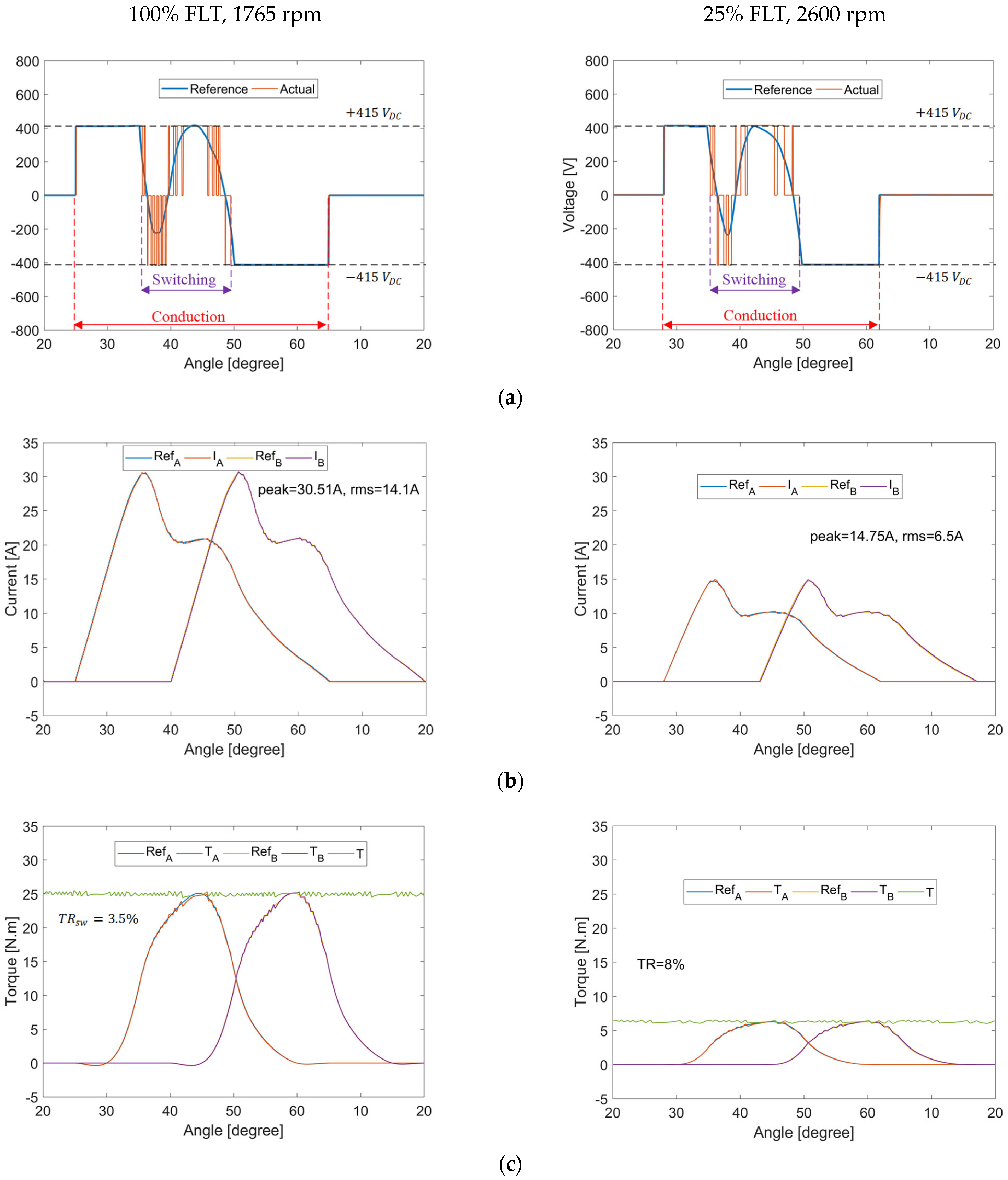
Results of the proposed TCF at 100% FLT at 1765 rpm and 25% FLT at 2600 rpm are shown in Figure 11. As illustrated in Figure 11a, although the conduction period is above , switching is required for only ; hence, the switching losses are reduced. The voltage demand in the control region reaches the dc-link voltage level, as shown in Figure 11a, revealing that further improvement in zero TR requires a higher dc-link voltage. Switching in the control region is reduced, thereby decreasing switching losses. Current and torque waveforms are demonstrated in Figure 11 parts b and c, respectively, showing a 3.5% at 100% FLT and 1765 rpm solely due to switching. Using a 0.1 A hysteresis band reduces the switching from 3.5% to 2.2%.
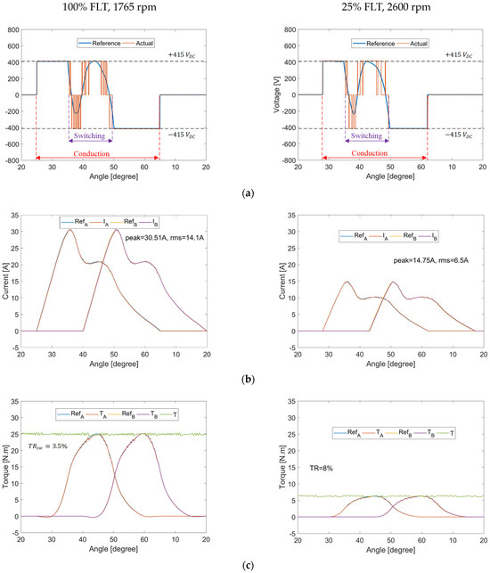
Figure 11.
SRM performance at 100% FLT and 1765 rpm and 25% FLT and 2600 rpm using TCF mode #2: (a) rate of change of flux linkage (voltage demand), (b) current waveforms, and (c) torque waveforms.
The SRM performance at 25% FLT and 2600 rpm shows 8% . The relatively high values of switching torque ripple at low torque levels, indicating the importance of a narrow hysteresis band. Fluxgate current transducers offer a 0.01% accuracy and linearity with the necessary 1 dB bandwidth, but at a financial cost.
5. Discussion
In the previous sections, the main goal was to propose current profiles that completely eliminate the commutation TR, allowing for an extended ripple-free operation. However, minimising the rms current and, hence, the Cu losses, is of prime importance. In this section, the effect of advancing/retarding the turn-on angle on the peak/rms current is investigated. Moreover, the performance of the proposed TCF is compared against the performance of conventional linear TSF, cos TSF, and DITC.
5.1. Effect of Turn-on Angle on Phase Current
The work presented in the previous sections focused on the operation of the proposed TCF, where the conduction period was centred at . The selection of this specific position was intuitive, given that has the highest N·m/A. Moreover, is the midpoint between the unaligned and aligned position, so for a conduction period, the operation will be confined in the positive torque-production region.
In this subsection, the effect of advancing/retarding the turn-on angle on the peak/rms current is investigated. The results are demonstrated in Figure 12 and summarised in Table 5.
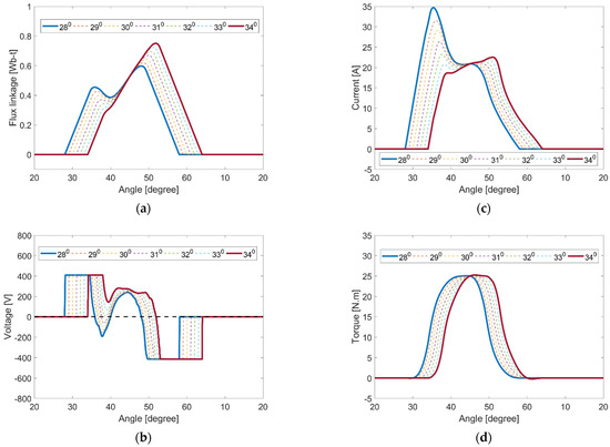
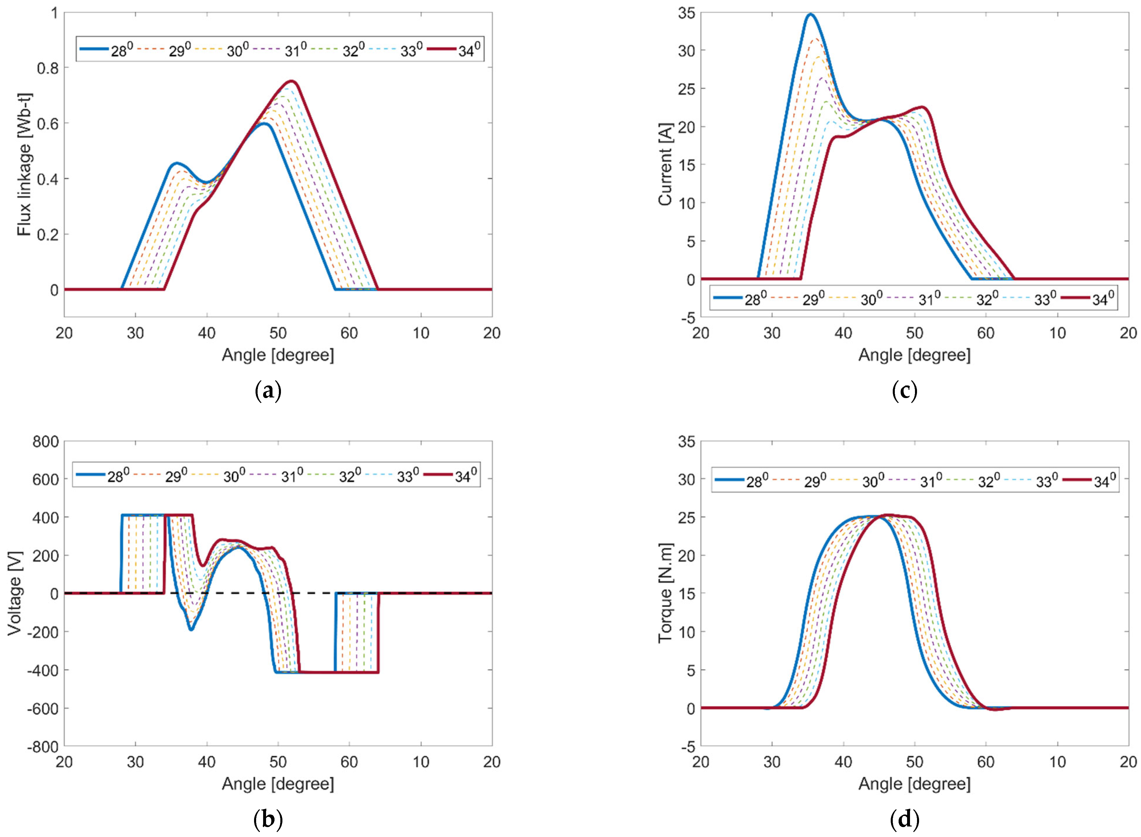
Figure 12.
Effect of turn-on angle: (a) flux linkage waveform, (b) rate of change of flux linkage (voltage demand), (c) current waveforms, and (d) torque waveforms.
Table 5.
Results for zero torque ripple, phase conduction with different turn-on angles.
The maximum speed in Section 3 employed a conduction period between and with a 12.66 A rms phase current at 1065 rpm and FLT. By advancing and retarding the conduction period, negative torque production is introduced, as shown in Figure 12d, but as Table 5 and Figure 12c show, with a retard of the turn-on angle, 1055 rpm at FLT can be reached, but with the rms phase current reduced from 12.66 A to 11.2 A (and with a reduced peak current from 29.1 A to 22.5 A). This rms current reduction reflects on copper loss reduction. Moreover, retarding the turn-on angle shifted the voltage demand in the control region above 0 V, as demonstrated in Figure 12b. Hence, soft switching only between 0 V and is required (no loop is required). More retarding in the turn-on angle beyond the will lead to an increase again in the rms and peak currents.
5.2. Comparison of Proposed TCF against Conventional TR-Minimisation Methods
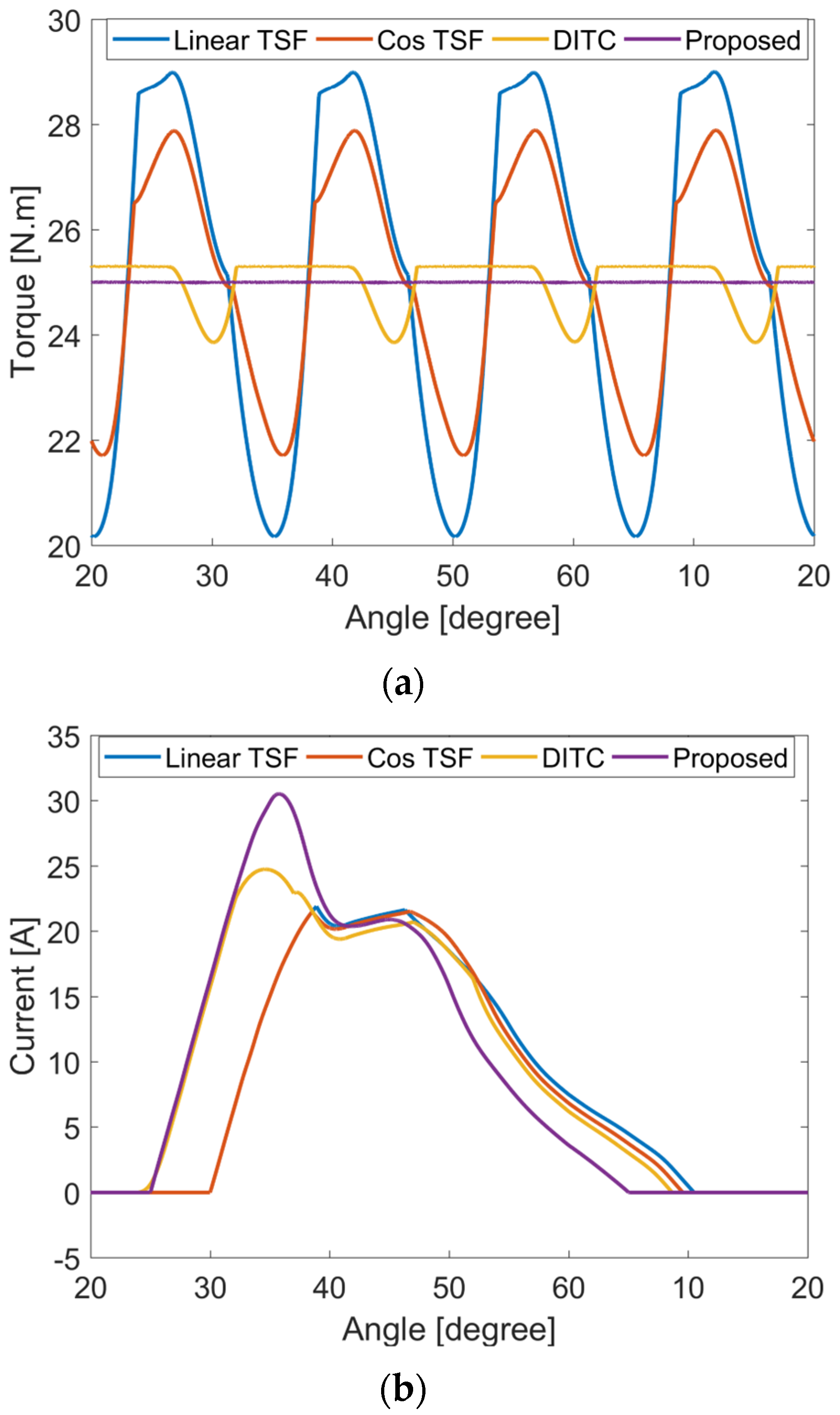
In this subsection, the performance of the proposed TCF is compared against the performance of linear TSF, cos TSF (benchmark conventional methods), and DITC (most advanced and dominant TR-minimisation approach) regarding commutation TR and the rms/peak current to further highlight the effectiveness of the proposed TCF. Two cases are selected: the first case is FLT and 1000 rpm, where the results are given in Figure 13, while the second case is FLT and 1765 rpm, with the results illustrated in Figure 14. Optimal turn-on/off angles are selected for each method for a fair comparison. A high sampling frequency with a low hysteresis band are deployed to eliminate the switching TR, leaving only TR due to commutation.
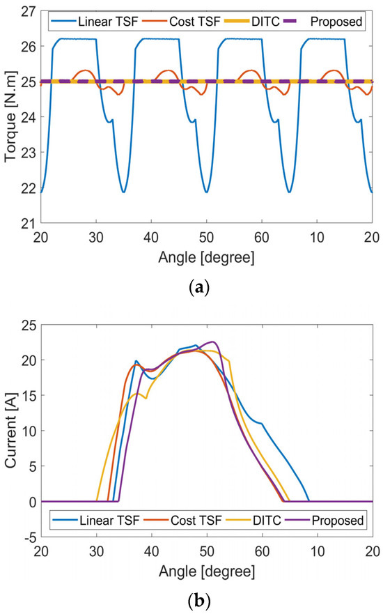
Figure 13.
Comparison of SRM performance at FLT and 1000 rpm using the proposed TCF and conventional TR-minimisation methods: (a) torque waveforms and (b) current waveforms.
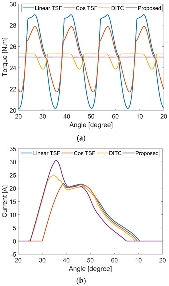
Figure 14.
Comparison of SRM performance at FLT and 1750 rpm using the proposed TCF and conventional TR-minimisation methods: (a) torque waveforms and (b) current waveforms.
Figure 13a shows that the linear TSF produces severe commutation TR during commutation (at 1000 rpm and FLT) due to the high non-linearity of the SRM, restraining the phase torque from tracking the reference torque near the unaligned and aligned positions.
Cos TSF takes into account the non-linear SRM torque-production characteristics; therefore, commutation TR is less than that of the linear TSF; however, TR is still sensed. One of the major drawbacks of conventional TSFs is that the turn-on angle cannot be advanced beyond the unaligned position, which hinders the process of current buildup. On the other hand, the turn-on angle can be advanced in DITC; hence, TR is completely eliminated. Finally, zero TR operation is achieved as well using the proposed TCF, where the commutation TR is also completely eliminated. The results are summarised in Table 6.
Table 6.
Performance comparison of conventional and proposed TR-minimisation methods at FLT and 1000 rpm.
Although DITC (with optimal turn-on/off angles) is able, as well as the proposed TCF, to completely eliminate the commutation TR component, the proposed TCF draws less rms current, as illustrated in Figure 13b, therefore reducing the Cu loss component and increasing the efficiency.
At higher speeds (1765 rpm, FLT), only the proposed TCF is capable of completely eliminating the commutation TR, as demonstrated in Figure 14a. Nevertheless, the complete elimination of commutation TR comes on the cost of current and, hence, efficiency. The proposed TCF draws a higher current, as demonstrated in Figure 14b (14.1 A rms); thus, the efficiency is reduced. The results are summarised in Table 7. It is worth mentioning that the increases in the rms and peak currents represent 11% and 5%, respectively. However, the SRM at 1765 rpm is operating at 118% of rated power.
Table 7.
Performance comparison of conventional and proposed TR-minimisation methods at FLT and 1750 rpm.
The results show that the proposed TCF achieves zero TR with the best efficiency from zero up to the base speed when compared to other TR-minimisation approaches. In addition, the proposed TCF extends the zero TR speed range up to 118% of the base speed, which cannot be achieved using any other method. Nevertheless, this comes at the expense of increased Cu losses. However, operation above the rated power should be only for limited duration.
Finally, Table 8 gives a comprehensive comparison of the proposed TCF against conventional TSF and DITC methods.
Table 8.
Comprehensive comparison of conventional and proposed TR-minimisation methods.
6. Conclusions
A new TCF has been proposed, investigated, and simulated, which exploits the maximum utilisation of the dc-link voltage at phase turn-on and turn-off. This extends the zero TR speed range significantly. This TCF is adaptable to any SRM with any number of phases and stator/rotor pole numbers. Only magnetic characteristics (either obtained using FEA or experimentally) are needed. A new concept, which differentiates between commutation TR (based on using a current source converter) and switching TR (based on using a voltage source converter), is introduced. The concept of TSF is generalised to include more than two phases conducting simultaneously. The SRM’s maximum speed range with theoretically zero TR was determined. The proposed TCF is characterised by low switching losses, as switching is required only for a conduction period equal to the stroke angle. In addition, soft switching is used as opposed to conventional TSFs that require either hard or at least hybrid switching. The proposed TCF was assessed on a 4φ, 8/6 SRM, where a ripple-free operation was possible up to 118% of the base speed. Theoretical results were established through simulations based on a widely studied research machine.
Author Contributions
Conceptualisation, A.A.-A. and M.E.; Analysis, A.A.-A.; Methodology, A.A.-A., M.E. and B.W.; Software, A.A.-A.; Supervision, B.W.; Writing—review and editing, A.A.-A., M.E. and B.W. All authors have read and agreed to the published version of the manuscript.
Funding
This research received no external funding.
Data Availability Statement
The original contributions presented in the study are included in the article, further inquiries can be directed to the corresponding author.
Conflicts of Interest
The authors declare no conflicts of interest.
Appendix A
This Appendix provides an overview of the SRM operation, modelling, and FEA results.
Appendix A.1. SRM Basics
The SRM is a double-salient machine (both the stator and rotor have salient poles usually made of laminated silicon steel) with a concentrated winding on the stator poles, with neither windings nor permanent magnets on the rotor. Each two opposite stator poles are connected either in series or in parallel, forming a phase. When the proper stator poles are excited, the rotor poles tend to rotate so as to align with the stator poles to minimise the reluctance of the flux path. The proper and sequential excitation of stator poles allows for the continuous rotation of the rotor.
Since the SRM is a double-salient machine, the phase-winding inductance is dependent on the rotor position and current excitation level. Torque, defined using (A1), is produced by the tendency of a rotor pole to align with the excited stator pole, thereby minimising flux path reluctance.
The rate of change of inductance with the rotor position determines the sign of the torque. Thus, negative (generating/braking) torque is possible, enabling a four-quadrant operation of the machine.
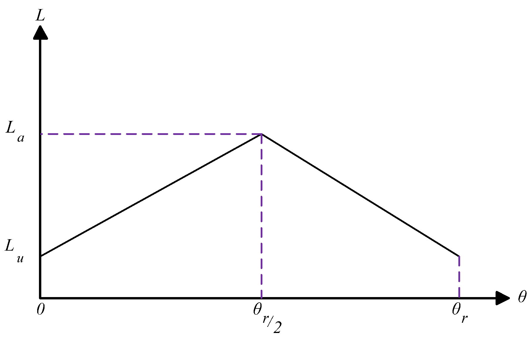
Figure A1 shows a typical inductance profile (inductance is assumed to vary linearly with the rotor position; that is, core saturation is ignored), where and are the unaligned and aligned (unsaturated) inductances, respectively.
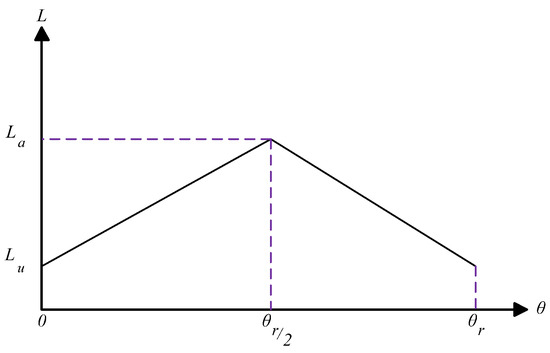
Figure A1.
Inductance profile.
Figure A1.
Inductance profile.
The rotor pole pitch is defined by:
For a 4φ, 8/6 SRM, the rotor pole pitch is . During the rising inductance value (), where the rotor moves from the unaligned position to the aligned position, positive (motoring) torque is produced for . During the falling inductance period (), where the rotor moves from the aligned position back to the unaligned position, negative (generating/braking) torque is produced for .
Appendix A.2. SRM Modelling
Since the interaction between SRM phase windings is minimal, the mutual effect between different phases is ignored, and the voltage equation is expressed using (A3) considering the phase-winding resistance.
Here, is the dc-link voltage, and R is the phase resistance.
The rate of change of flux linkage can be divided into two parts, and then the voltage equation is defined by:
where is the rotor speed (rad/s).
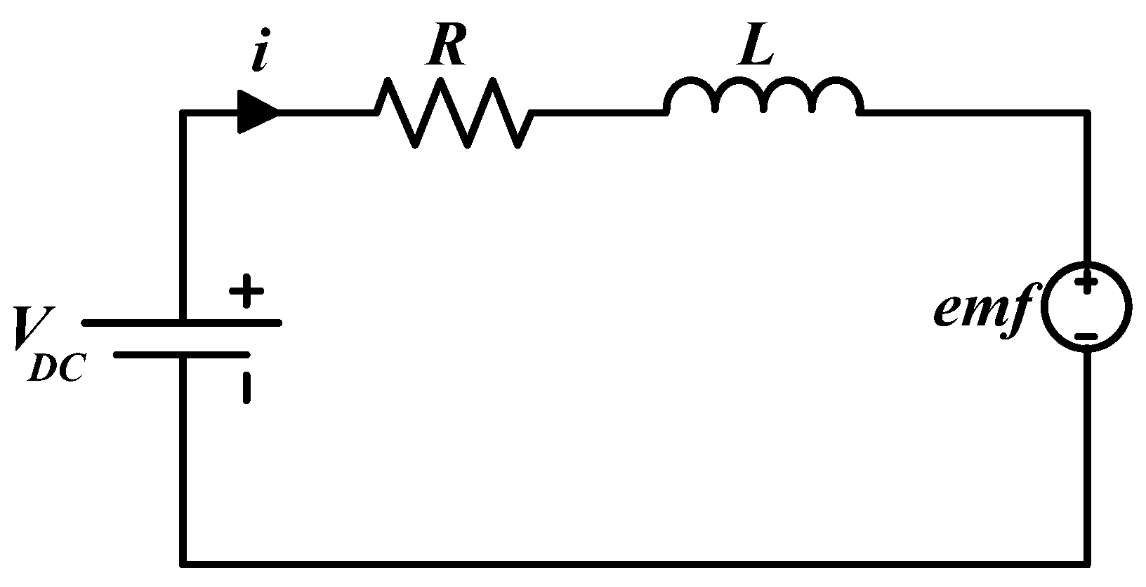
The three terms on the right-hand side in (A4) represent the winding resistive voltage drop, inductive voltage drop, and back electromotive force (emf) of the SRM, respectively. Figure A2 shows the equivalent circuit for a single phase of the SRM.

Figure A2.
SRM single-phase equivalent circuit.
Figure A2.
SRM single-phase equivalent circuit.
Due to the SRM’s high non-linearity, developing a mathematical model is a tedious task. Hence, 2D look-up tables (LUTs) are used to store the flux linkage–current–angle (λ-i-) characteristics and the torque–current–angle (T-i-) characteristics. These facilitate an accurate model that accounts for non-linearity and avoids a sophisticated mathematical model. The data used to create the look-up tables are obtained either experimentally or from FEA. The simulation diagram for a single phase of an SRM using LUTs is shown in Figure A3.
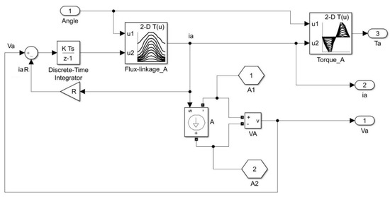
Figure A3.
SRM single-phase simulation diagram using LUTs.
Figure A3.
SRM single-phase simulation diagram using LUTs.

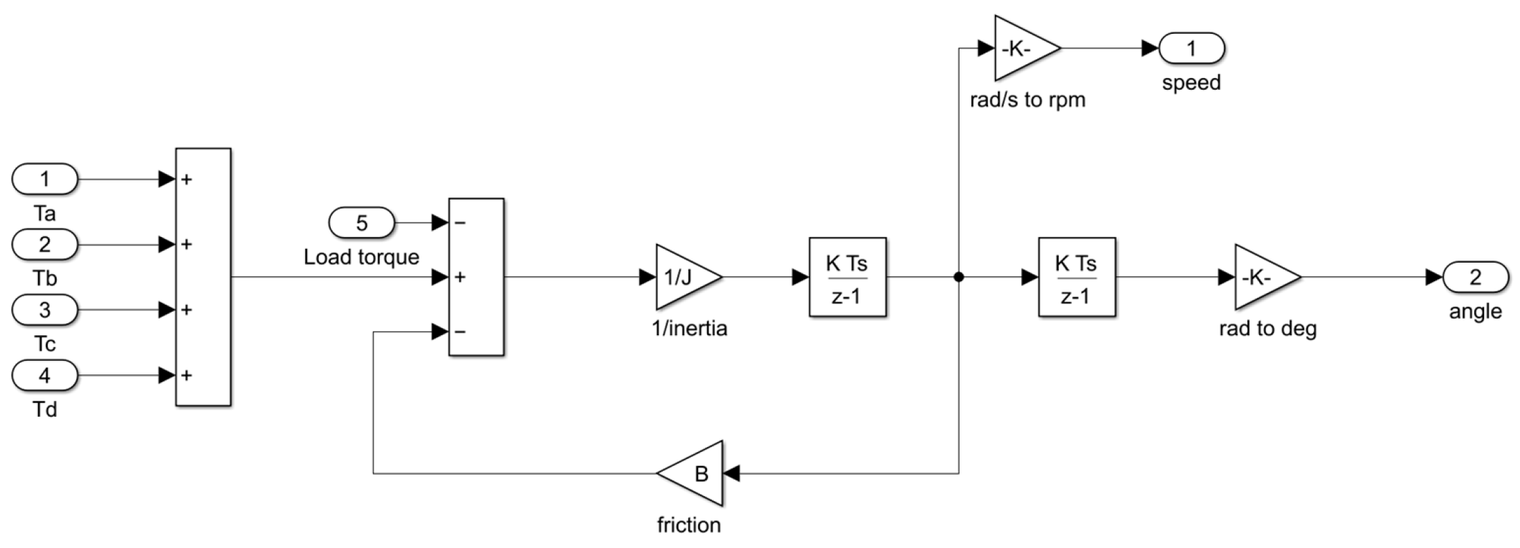
The total developed torque, , is the summation of the time of all phase torques and defined by:
Finally, the equation of mechanical motion is:
where J is the rotor inertia, is the coefficient of friction, and is the load torque.
The mechanical part is simulated as demonstrated in Figure A4.
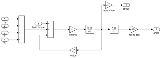
Figure A4.
Simulation of SRM mechanical part.
Figure A4.
Simulation of SRM mechanical part.
A step size of is used for simulation, and the solver is ode45 (Dormand–Prince).
Appendix A.3. Three-Dimensional Finite Element Analysis Results
The SRM is a highly non-linear machine due to its double-salient nature. Identifying the SRM magnetic characteristics is of prime importance for proper operation. Generally, two approaches are available [65]: the experimental approach, where the voltage and current are used to identify the SRM flux, and the finite element analysis (FEA) approach. FEA software, like Ansys Maxwell used for this analysis, gives an accurate and reliable SRM model reflecting actual SRM performance. Figure A5 shows the 3D model built using Ansys Maxwell software (version 13) to study the SRM using the parameters given in Table 1.
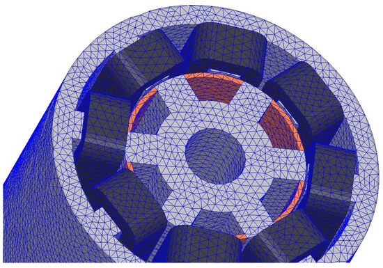
Figure A5.
SRM 3D FEA model.
Figure A5.
SRM 3D FEA model.
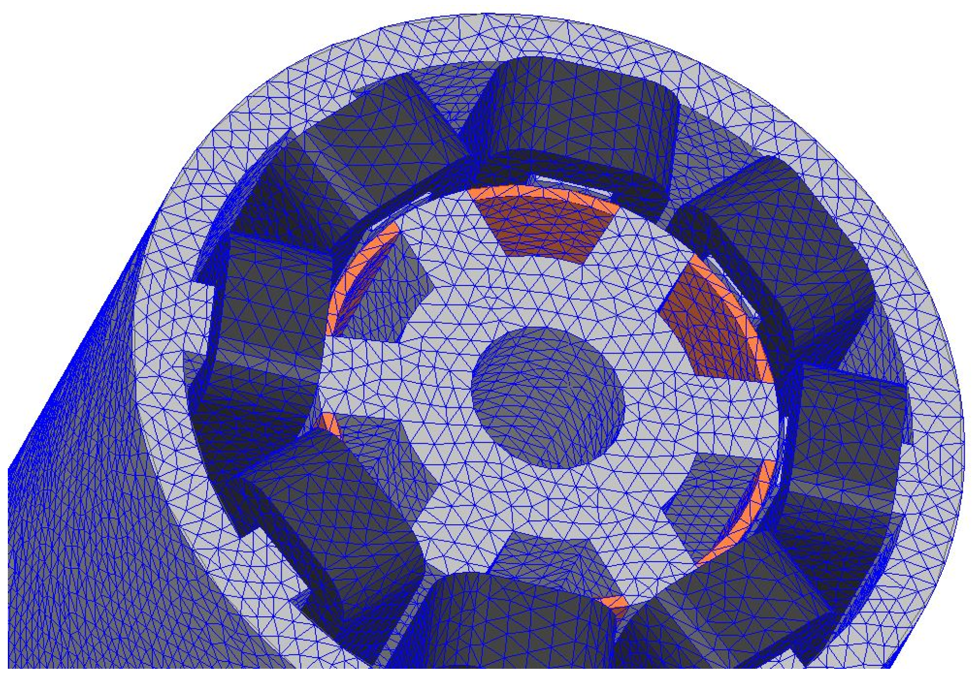
Figure A6 shows the flux linkage/current characteristics at different rotor positions.
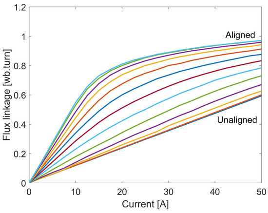
Figure A6.
Flux linkage–current–angle characteristics.
Figure A6.
Flux linkage–current–angle characteristics.
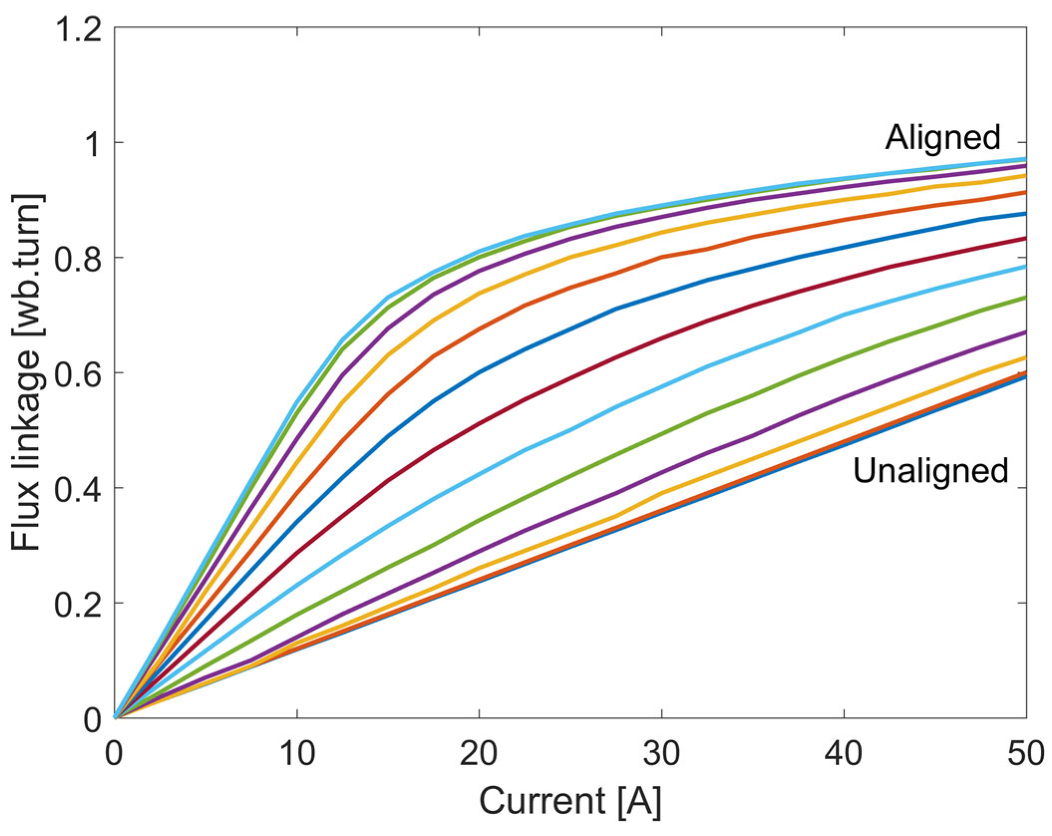
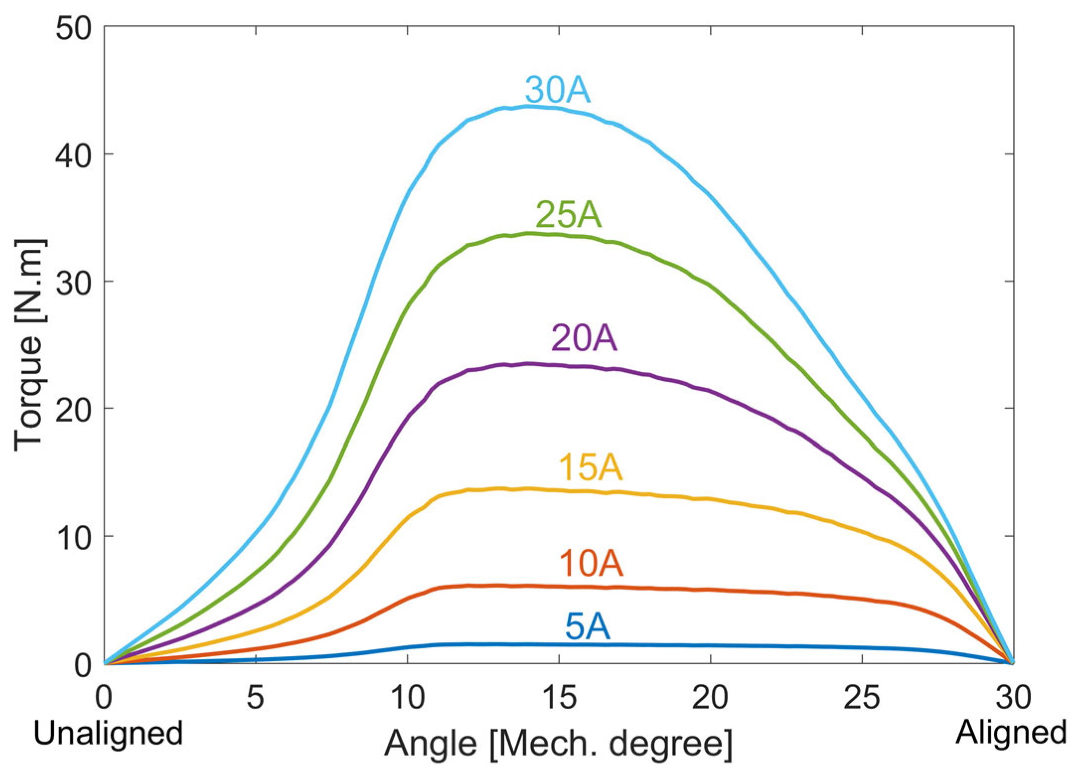
Figure A7 shows the torque/angle characteristics at different current levels. These characteristics are stored in LUTs as highlighted in Figure A3.

Figure A7.
Torque–current–angle characteristics.
Figure A7.
Torque–current–angle characteristics.
References
- Rahman, K.; Fahimi, B.; Suresh, G.; Rajarathnam, A.; Ehsani, M. Advantages of switched reluctance motor applications to EV and HEV: Design and control issues. IEEE Trans. Ind. Appl. 2000, 36, 111–121. [Google Scholar] [CrossRef]
- Wang, S.; Zhan, Q.; Ma, Z.; Zhou, L. Implementation of a 50-kW four-phase switched reluctance motor drive system for hybrid electric vehicle. IEEE Trans. Magn. 2005, 41, 501–504. [Google Scholar] [CrossRef]
- Makino, H.; Kosaka, T.; Matsui, N. Digital PWM-control-based active vibration cancellation for switched reluctance motors. IEEE Trans. Ind. Appl. 2015, 51, 4521–4530. [Google Scholar] [CrossRef]
- Bostanci, E.; Moallem, M.; Parsapour, A.; Fahimi, B. Opportunities and Challenges of Switched Reluctance Motor Drives for Electric Propulsion: A Comparative Study. IEEE Trans. Transp. Electrif. 2017, 3, 58–75. [Google Scholar] [CrossRef]
- Abdel-Aziz, A.A.; Ahmed, K.H.; Wang, S.; Massoud, A.M.; Williams, B.W. A Neutral-Point Diode-Clamped Converter with Inherent Voltage-Boosting for a Four-Phase SRM Drive. IEEE Trans. Ind. Electron. 2020, 67, 5313–5324. [Google Scholar] [CrossRef]
- Abdel-Aziz, A.; Elgenedy, M.A.; Williams, B. A Comparative Review of Three Different Power Inverters for DC–AC Applications. Energies 2023, 16, 7254. [Google Scholar] [CrossRef]
- Wang, L.; Tang, Z.; Zhang, P.; Liu, X.; Wang, D.; Li, X. Double Extended Sliding-Mode Observer-Based Synchronous Estimation of Total Inertia and Load Torque for PMSM-driven Spindle-Tool Systems. IEEE Trans. Ind. Inform. 2023, 19, 8496–8507. [Google Scholar] [CrossRef]
- Gan, C.; Wu, J.; Sun, Q.; Kong, W.; Li, H.; Hu, Y. A review on machine topologies and control techniques for low-noise switched reluctance motors in electric vehicle applications. IEEE Access 2018, 6, 31430–31443. [Google Scholar] [CrossRef]
- Fang, G.; Scalcon, F.P.; Xiao, D.; Vieira, R.P.; Gründling, H.A.; Emadi, A. Advanced Control of Switched Reluctance Motors (SRMs): A Review on Current Regulation, Torque Control, and Vibration Suppression. IEEE Open J. Ind. Electron. Soc. 2021, 2, 280–301. [Google Scholar] [CrossRef]
- Deng, X.; Mecrow, B.; Wu, H.; Martin, R. Design and development of low torque ripple variable-speed drive system with six-phase switched reluctance motors. IEEE Trans. Energy Convers. 2018, 33, 420–429. [Google Scholar] [CrossRef]
- Jiang, J.W.; Bilgin, B.; Emadi, A. Three-phase 24/16 switched reluctance machine for a hybrid electric powertrain. IEEE Trans. Transp. Electrif. 2017, 3, 76–85. [Google Scholar] [CrossRef]
- Desai, P.C.; Krishnamurthy, M.; Schofield, N.; Emadi, A. Novel switched reluctance machine configuration with higher number of rotor poles than stator poles: Concept to implementation. IEEE Trans. Ind. Electron. 2010, 57, 649–659. [Google Scholar] [CrossRef]
- Bilgin, B.; Emadi, A.; Krishnamurthy, M. Design considerations for switched reluctance machines with a higher number of rotor poles. IEEE Trans. Ind. Electron. 2012, 59, 3745–3756. [Google Scholar] [CrossRef]
- Bilgin, B.; Emadi, A.; Krishnamurthy, M. Comprehensive evaluation of the dynamic performance of a 6/10 SRM for traction application in PHEVs. IEEE Trans. Ind. Electron. 2013, 60, 2564–2575. [Google Scholar] [CrossRef]
- Lin, J.; Schofield, N.; Emadi, A. External-rotor 6-10 switched reluctance motor for an electric bicycle. IEEE Trans. Transp. Electrif. 2015, 1, 348–356. [Google Scholar] [CrossRef]
- Lee, J.W.; Kim, H.S.; Kwon, B.I.; Kim, B.T. New rotor shape design for minimum torque ripple of SRM using FEM. IEEE Trans. Magn. 2004, 40, 754–757. [Google Scholar] [CrossRef]
- Li, G.; Ojeda, J.; Hlioui, S.; Hoang, E.; Lecrivain, M.; Gabsi, M. Modification in rotor pole geometry of mutually coupled switched reluctance machine for torque ripple mitigating. IEEE Trans. Magn. 2012, 48, 2025–2034. [Google Scholar] [CrossRef]
- Choi, Y.K.; Yoon, H.S.; Koh, C.S. Pole-shape optimization of switched-reluctance motor for torque ripple reduction. IEEE Trans. Magn. 2007, 43, 1797–1800. [Google Scholar] [CrossRef]
- Sheth, N.; Rajagopal, K. Torque profiles of a switched reluctance motor having special pole face shapes and asymmetric stator poles. IEEE Trans. Magn. 2004, 40, 2035–2037. [Google Scholar] [CrossRef]
- Lee, D.-H.; Pham, T.H.; Ahn, J.-W. Design and operation characteristics of four-two pole high-speed SRM for torque ripple reduction. IEEE Trans. Ind. Electron. 2013, 60, 3637–3643. [Google Scholar] [CrossRef]
- Sheth, N.; Rajagopal, K. Optimum pole arcs for a switched reluctance motor for higher torque with reduced ripple. IEEE Trans. Magn. 2003, 39, 3214–3216. [Google Scholar] [CrossRef]
- Husain, T.; Elrayyah, A.; Sozer, Y.; Husain, I. Unified control for switched reluctance motors for wide speed operation. IEEE Trans. Ind. Electron. 2019, 66, 3401–3411. [Google Scholar] [CrossRef]
- Almirante, I.; Lorenzani, E. Simple Strategy for Torque Ripple Minimization in Switched Reluctance Motor Drives. Energies 2023, 16, 6885. [Google Scholar] [CrossRef]
- Hamouda, M.; Al-Amyal, F.; Odinaev, I.; Ibrahim, M.N.; Számel, L. A Novel Universal Torque Control of Switched Reluctance Motors for Electric Vehicles. Mathematics 2022, 10, 3833. [Google Scholar] [CrossRef]
- Schulz, S.; Rahman, K. High-performance digital PI current regulator for EV switched reluctance motor drives. IEEE Trans. Ind. Appl. 2003, 39, 1118–1126. [Google Scholar] [CrossRef]
- Abdel-Aziz, A.A.; Elgenedy, M.A.; Williams, B.W. Model predictive current control for a low-cost shunt active power filter. CSEE J. Power Energy Syst. 2023, 1–11. Available online: https://ieeexplore.ieee.org/document/10246184 (accessed on 30 June 2024).
- Abdel-Aziz, A.A.; Elgenedy, M.A.; Williams, B.W. Two-Leg Neutral-Point Diode-Clamped Active Front-End Rectifier. IEEE J. Emerg. Sel. Top. Power Electron. 2024, 12, 405–419. [Google Scholar] [CrossRef]
- Mikail, R.; Husain, I.; Sozer, Y.; Islam, M.; Sebastian, T. A fixed switching frequency predictive current control method for switched reluctance machines. IEEE Trans. Ind. Appl. 2014, 50, 3717–3726. [Google Scholar] [CrossRef]
- Ye, J.; Malysz, P.; Emadi, A. A fixed-switching-frequency integral sliding mode current controller for switched reluctance motor drives. IEEE J. Emerg. Sel. Top. Power Electron. 2015, 3, 381–394. [Google Scholar] [CrossRef]
- Li, X.; Shamsi, P. Model predictive current control of switched reluctance motors with inductance auto-calibration. IEEE Trans. Ind. Electron. 2016, 63, 3934–3941. [Google Scholar] [CrossRef]
- Peng, F.; Ye, J.; Emadi, A. A digital PWM current controller for switched reluctance motor drives. IEEE Trans. Power Electron. 2016, 31, 7087–7098. [Google Scholar]
- Zhang, X.; Yang, Q.; Ma, M.; Lin, Z.; Yang, S. A switched reluctance motor torque ripple reduction strategy with deadbeat current control and active thermal management. IEEE Trans. Veh. Technol. 2020, 69, 317–327. [Google Scholar] [CrossRef]
- Mikail, R.; Husain, I.; Sozer, Y.; Islam, M.; Sebastian, T. Torque-ripple minimization of switched reluctance machines using current profiling. IEEE Trans. Ind. Appl. 2013, 49, 1258–1267. [Google Scholar] [CrossRef]
- Mikail, R.; Husain, I.; Islam, M.; Sozer, Y.; Sebastian, T. Four quadrant torque ripple minimization of switched reluctance machine through current profiling with mitigation of rotor eccentricity problem and sensor errors. IEEE Trans. Ind. Appl. 2015, 51, 2079–2104. [Google Scholar] [CrossRef]
- Chapman, P.; Sudhoff, S. Design and precise realization of optimized current waveforms for an 8/6 switched reluctance drive. IEEE Trans. Power Electron. 2002, 17, 76–83. [Google Scholar] [CrossRef]
- Henriques, L.; Branco, P.C.; Rolim, L.; Suemitsu, W. Proposition of an offline learning current modulation for torque-ripple reduction in switched reluctance motors: Design and experimental evaluation. IEEE Trans. Ind. Electron. 2002, 49, 665–676. [Google Scholar] [CrossRef]
- Lin, Z.; Reay, D.; Williams, B.; He, X. Torque ripple reduction in switched reluctance motor drives using B-spline neural networks. IEEE Trans. Ind. Appl. 2006, 42, 1445–1453. [Google Scholar] [CrossRef]
- Sahoo, S.; Panda, S.; Xu, J. Iterative learning-based high-performance current controller for switched reluctance motors. IEEE Trans. Energy Convers. 2004, 19, 491–498. [Google Scholar] [CrossRef]
- Sahoo, S.; Panda, S.; Xu, J.-X. Indirect torque control of switched reluctance motors using iterative learning control. IEEE Trans. Power Electron. 2005, 20, 200–208. [Google Scholar] [CrossRef]
- Inderka, R.; De Doncker, R. High-dynamic direct average torque control for switched reluctance drives. IEEE Trans. Ind. Appl. 2003, 39, 1040–1045. [Google Scholar] [CrossRef]
- Cai, Y.; Dong, Z.; Liu, H.; Liu, Y.; Wu, Y. Direct Instantaneous Torque Control of SRM Based on a Novel Multilevel Converter for Low Torque Ripple. World Electr. Veh. J. 2023, 14, 140. [Google Scholar] [CrossRef]
- Sun, Q.; Wu, J.; Gan, C. Optimized Direct Instantaneous Torque Control for SRMs With Efficiency Improvement. IEEE Trans. Ind. Electron. 2021, 68, 2072–2082. [Google Scholar] [CrossRef]
- Sheng, L.; Wang, G.; Fan, Y.; Liu, J.; Liu, D.; Mu, D. An Improved Direct Predictive Torque Control for Torque Ripple and Copper Loss Reduction in SRM Drive. Appl. Sci. 2023, 13, 5319. [Google Scholar] [CrossRef]
- Cheok, A.; Fukuda, Y. A new torque and flux control method for switched reluctance motor drives. IEEE Trans. Power Electron. 2002, 17, 543–557. [Google Scholar] [CrossRef]
- Elgenedy, M.A.; Abdel-Khalik, A.S.; Massoud, A.M.; Ahmed, S. Indirect field-oriented control of five-phase induction motor based on SPWM-CSI. In Proceedings of the IEEE International Conference on Electrical Machines (ICEM), Berlin, Germany, 2–5 September 2014; pp. 2101–2106. [Google Scholar]
- Elgenedy, M.A.; Massoud, A.M.; Ahmed, S. Energy in smart grid: Strategies and technologies for efficiency enhancement. In Proceedings of the IEEE 2015 First Workshop on Smart Grid and Renewable Energy (SGRE), Doha, Qatar, 22–23 March 2015; pp. 1–6. [Google Scholar]
- Reddy, P.; Ronaki, D.; Perumal, P. Efficiency improvement and torque ripple minimization of four-phase switched reluctance motor drive using new direct torque control strategy. IET Electr. Power Appl. 2020, 14, 52–61. [Google Scholar] [CrossRef]
- Yan, N.; Cao, X.; Deng, Z. Direct torque control for switched reluctance motor to obtain high torque-ampere ratio. IEEE Trans. Ind. Electron. 2019, 66, 5144–5152. [Google Scholar] [CrossRef]
- Xu, A.; Shang, C.; Chen, J.; Zhu, J.; Han, L. A new control method based on DTC and MPC to reduce torque ripple in SRM. IEEE Access 2019, 7, 68584–68593. [Google Scholar] [CrossRef]
- Inderka, R.; De Doncker, R. DITC-direct instantaneous torque control of switched reluctance drives. IEEE Trans. Ind. Appl. 2003, 39, 1046–1051. [Google Scholar] [CrossRef]
- Fuengwarodsakul, N.; Menne, M.; Inderka, R.; DeDoncker, R. High-dynamic four-quadrant switched reluctance drive based on DITC. IEEE Trans. Ind. Appl. 2005, 41, 1232–1242. [Google Scholar] [CrossRef]
- Brauer, H.J.; Hennen, M.D.; De Doncker, R.W. Control for Polyphase Switched Reluctance Machines to Minimize Torque Ripple and Decrease Ohmic Machine Losses. IEEE Trans. Power Electron. 2012, 27, 370–378. [Google Scholar] [CrossRef]
- Song, S.; Huang, S.; Zhao, Y.; Zhao, X.; Duan, X.; Ma, R.; Liu, W. Torque Ripple Reduction of Switched Reluctance Machine with Torque Distribution and Online Correction. IEEE Trans. Ind. Electron. 2023, 70, 8842–8852. [Google Scholar] [CrossRef]
- Ling, X.; Zhou, C.; Yang, L.; Zhang, J. Torque Ripple Suppression Method of Switched Reluctance Motor Based on an Improved Torque Distribution Function. Electronics 2022, 11, 1552. [Google Scholar] [CrossRef]
- Vujičić, V.P. Minimization of Torque Ripple and Copper Losses in Switched Reluctance Drive. IEEE Trans. Power Electron. 2012, 27, 388–399. [Google Scholar] [CrossRef]
- Xue, X.D.; Cheng, K.W.E.; Ho, S.L. Optimization and Evaluation of Torque-Sharing Functions for Torque Ripple Minimization in Switched Reluctance Motor Drives. IEEE Trans. Power Electron. 2009, 24, 2076–2090. [Google Scholar] [CrossRef]
- Lee, D.-H.; Liang, J.; Lee, Z.-G.; Ahn, J.-W. A Simple Nonlinear Logical Torque Sharing Function for Low-Torque Ripple SR Drive. IEEE Trans. Ind. Electron. 2009, 56, 3021–3028. [Google Scholar] [CrossRef]
- Ye, J.; Bilgin, B.; Emadi, A. An Extended-Speed Low-Ripple Torque Control of Switched Reluctance Motor Drives. IEEE Trans. Power Electron. 2015, 30, 1457–1470. [Google Scholar] [CrossRef]
- Ye, J.; Bilgin, B.; Emadi, A. An Offline Torque Sharing Function for Torque Ripple Reduction in Switched Reluctance Motor Drives. IEEE Trans. Energy Convers. 2015, 30, 726–735. [Google Scholar] [CrossRef]
- Ge, L.; Fan, Z.; Huang, J.; Cheng, Q.; Zhao, D.; Song, S.; De Doncker, R.W. Model Predictive Control of Switched Reluctance Machines with Online Torque Sharing Function Based on Optimal Flux-linkage Curve. IEEE Trans. Transp. Electrif. 2023. [Google Scholar] [CrossRef]
- Feng, L.; Sun, X.; Yang, Z.; Diao, K. Optimal Torque Sharing Function Control for Switched Reluctance Motors Based on Active Disturbance Rejection Controller. IEEE/ASME Trans. Mechatron. 2023, 28, 2600–2608. [Google Scholar] [CrossRef]
- Li, H.; Bilgin, B.; Emadi, A. An Improved Torque Sharing Function for Torque Ripple Reduction in Switched Reluctance Machines. IEEE Trans. Power Electron. 2019, 34, 1635–1644. [Google Scholar] [CrossRef]
- Abdel-Aziz, A.; MacRae, E.; McNeill, N.; Ahmed, K.; Massoud, A.; Williams, B. A New Torque Ripple Minimization Approach for Switched Reluctance Drives. In Proceedings of the 2022 IEEE 1st Industrial Electronics Society Annual On-Line Conference (ONCON), Kharagpur, India, 9–11 December 2022; pp. 1–6. [Google Scholar] [CrossRef]
- MacRae, E.; Abdel-Aziz, A.; Ahmed, K.; Pollock, R.; Williams, B.W. Genetic Algorithm Based Approach of SRM Current Profiling for Torque Control and Minimal Copper Losses. In Proceedings of the 2023 IEEE International Electric Machines & Drives Conference (IEMDC), San Francisco, CA, USA, 15–18 May 2023. [Google Scholar]
- Yao, S.; Zhang, W. A Simple Strategy for Parameters Identification of SRM Direct Instantaneous Torque Control. IEEE Trans. Power Electron. 2018, 33, 3622–3630. [Google Scholar] [CrossRef]


Disclaimer/Publisher’s Note: The statements, opinions and data contained in all publications are solely those of the individual author(s) and contributor(s) and not of MDPI and/or the editor(s). MDPI and/or the editor(s) disclaim responsibility for any injury to people or property resulting from any ideas, methods, instructions or products referred to in the content. |
© 2024 by the authors. Licensee MDPI, Basel, Switzerland. This article is an open access article distributed under the terms and conditions of the Creative Commons Attribution (CC BY) license (https://creativecommons.org/licenses/by/4.0/).