Article

FPGA-Based Speed Control Strategy of PMSM Using Improved Beetle Antennae Search Algorithm

1
School of Equipment Engineering, Shenyang Ligong University, Shenyang 110159, China
2
School of Automotive and Transportation, Shenyang Ligong University, Shenyang 110159, China
*
Author to whom correspondence should be addressed.
Energies 2024, 17(8), 1870; https://doi.org/10.3390/en17081870
Submission received: 19 February 2024 / Revised: 5 April 2024 / Accepted: 8 April 2024 / Published: 14 April 2024

Abstract

:
To improve performance in terms of overshoot and motor response speed when a permanent-magnet synchronous motor (PMSM) with a proportional–integral (PI) controller is subjected to external disturbances, this paper proposes a speed control strategy based on an enhanced Beetle Antennae Search algorithm, which allows for adjustable parameters of the PI controller within a certain range. Firstly, to enhance the global and local search capabilities of each individual beetle, the step size was improved by linearly decreasing it. Secondly, a simulation model of a PMSM closed-loop control system was built to verify the effectiveness of the improved Beetle Antennae Search (BAS) algorithm. Finally, a linear feedback shift register model that generates four random numbers was developed on a field-programmable gate array (FPGA). The improved BAS algorithm for the PMSM control system was implemented on an FPGA using the Verilog hardware description language, and the feasibility of the system was verified through hardware simulation. Additionally, the hardware resource consumption on different FPGA platforms was analyzed. The simulation results demonstrate that the proposed new speed control strategy can reduce the overshoot and improve the motor response speed.

1. Introduction

Permanent-magnet synchronous motors have been extensively used in many Internet of Things applications, such as electric vehicles, robots, and aerospace [1]. The stability and rapidity of motor control are crucial indicators for PMSM control systems. The proportional–integral (PI) controller is used for speed control in the PMSM control system. It is vital to realize the proportional and integral gain tuning parameters of the PI controller for accurate speed control. However, when the model of the controlled object changes, the PI control strategy may not be sufficient to meet the control requirements of the PMSM with respect to its complex structure. As a result, PI control strategies may suffer from significant overshoots, sophisticated parameter settings, and slow motor response speeds. To address these issues, several studies have been performed. For example, sliding mode control [2], a model reference adaptive system [3], model predictive control [4], the Extended Kalman Filter [5], and intelligent optimization algorithms [6,7,8] have been investigated. These techniques are aimed at achieving motor speed control with a minimal overshoot and a rapid response. Intelligent optimization algorithms not only improve system performance but also play a significant role in system performance optimization, especially when dealing with complex optimization problems. These complex problems may involve high dimensions, nonlinearity, and non-convexity, features that make traditional optimization methods difficult to effectively address. Xie et al. [6] proposed a speed estimation strategy for a PMSM based on a particle swarm optimization Kalman filter (KF) sequence algorithm. Chen et al. [7] optimized the parameters of a fractional-order PID controller of a PMSM using various intelligent optimization methods. Guo et al. [8] applied the Fish Migration Optimization (FMO) algorithm to tune the PID parameters, enhancing the robustness of the PID controller. These intelligent optimization algorithms are computationally cumbersome and arduous to implement using hardware. Therefore, a simple and adaptable intelligent optimization algorithm is necessary and should be embedded into the PMSM speed control system to achieve more efficient control. Considering the practical application of algorithms, it is imperative to study how to implement the algorithm in hardware.
In recent years, there has been a growing focus on intelligent optimization algorithms in various fields of research. These algorithms, which require minimal prior knowledge and assumptions, autonomously seek optimal solutions and exhibit advantages when dealing with complex nonlinear and high-dimensional problems. Wild Horse Optimization (WHO) [9], Gray Wolf Optimization (GWO) [10], the Beetle Antennae Search (BAS) algorithm [11], and Intelligent Water Drop (IWD) [12] are among these introduced algorithms. The BAS algorithm has been successfully applied in various domains owing to its outstanding performance in tackling complex optimization problems. The BAS algorithm has been successfully applied in various fields, such as the spring design problem [13], the geometric parameter identification of medical robots [14], triaxial accelerometers [15], and robot path planning [16]. Additionally, its fast convergence rate has made it widely popular in other fields, like portfolio management [17], robot arm calibration methods [18], exoskeleton robots [19], and economic load distribution problems [20]. The BAS demonstrates a rapid convergence rate and strong optimization capabilities, allowing it to maintain excellent solution performance even amidst noise and uncertainty. Zhang et al. [13] demonstrated the convergence and stability of the BAS algorithm, and they successfully applied the algorithm to six engineering cases with high requirements for real-time optimization. Additionally, Refs. [17,18,19,20] also applied the BAS algorithm to other engineering domains, meeting diverse real-time optimization needs. Compared to other mathematical control algorithms, the BAS algorithm presents several advantages when utilized in the speed loop of PMSM control systems. These advantages encompass its global optimization capability, adaptability, high robustness, simplicity, and parallelization ability. Therefore, the BAS method proves suitable for solving the PI controller parameter optimization problem.
However, due to the characteristics of a multivariable, nonlinear, and strongly coupled PMSM system, it is difficult to apply the BAS algorithm directly to the PMSM system. This area has not received extensive research attention, which is the motivation for our present study. This paper addresses the speed control problem of the PMSM system by studying how to utilize the BAS in the PMSM system and addressing its limitations to optimize the parameters of the PI controller and enhance the performance of the control system. Additionally, an FPGA has the advantages of parallelism capability, flexibility, high performance, and low power consumption compared to conventional hardware. An unrivaled advantage is that its hardware implementation can be customized [21,22]. Based on these unique advantages, FPGAs are widely used in various fields [23,24,25]. To date, several metaheuristic algorithms have been implemented on the FPGA platform and successfully applied to practical engineering, such as the BAS algorithm [26], genetic algorithm [27], particle swarm algorithm [28], cuckoo search algorithm [29], etc. An FPGA can process large amounts of data to meet high-performance requirements. Of particular importance is the advantage that the FPGA can respond in microseconds to meet the real-time requirements of the system. Consequently, the FPGA is well suited for PMSM control systems. However, due to the complex structure of a PMSM control system involving a large number of mathematical functions and the existence of floating-point calculations in the BAS algorithm, it is not easy to implement both of them on an FPGA.
This paper proposes an LDSBAS (Linear Decreasing Step Beetle Antennae Search) algorithm, which enhances the beetle’s ability to perform global and local searches while allowing adjustable parameters within a certain range for the PI controller. Based on this algorithm, we investigate the LDSBAS-PI control strategy. When the PMSM control system is subjected to external disturbances, compared to the conventional PI controller and BAS-based controller, the LDSBAS-PI control strategy exhibits better system performance in minimizing the overshoot and improving the motor response speed. Moreover, we implemented the PMSM control system based on the LDSBAS algorithm on an FPGA. The main contributions of this paper are as follows:
  • In this paper, we propose an LDSBAS algorithm to solve the optimization problem of PI controller parameters. The LDSBAS algorithm linearly decreases the search step length such that the beetle’s global and local search capabilities are significantly improved compared with the traditional BAS algorithm.
  • The LFSR model, which has the ability to generate four random numbers, is developed for the first time on an FPGA platform. Compared to the existing LFSR model, which can generate only one random number, the model that we propose can provide more random numbers.
  • This paper solves the problem of implementing a PMSM control system based on the BAS algorithm on an FPGA and provides a more feasible solution for the application of intelligent optimization algorithms in PMSM control systems.
  • The PMSM control system presented in this paper, which is based on the LDSBAS algorithm, was developed using a register transfer level description. This approach directly represents the underlying circuitry and meets the need for dynamic function expansion.
This paper is organized as follows: In Section 2, we offer a succinct overview of the mathematical model pertaining to a permanent-magnet synchronous motor. The LDSBAS algorithm is presented in Section 3. Section 4 describes the LDSBAS algorithm in a hardware description language. Section 5 proposes the PMSM control system based on the LDSBAS algorithm. We built and simulated the PMSM control system using Simulink to demonstrate the effectiveness of the LDSBAS algorithm, as described in Section 6. In Section 7, hardware simulations of the PMSM control system using the LDSBAS algorithm are presented, the resource consumption on different FPGA platforms is discussed, and the feasibility of the hardware implementation of the LDSBAS algorithm is verified. Concluding remarks are made in Section 8.

2. Mathematical Model of PMSM

Within the field-oriented theory and assuming an unsaturated magnetic circuit while disregarding hysteresis and eddy current losses, the mathematical model of the permanent-magnet synchronous motor (PMSM) can be described in the rotor reference frame of d q -axes by considering three-phase sinusoidal stator windings in space.
i ˙ d i ˙ q = R s L d L q L d ω e L d L q ω e R s L q i d i q + 1 L d 0 0 1 L q u d u q + 0 φ f L q ω e ,
where the superscript “.” represents differentiation, R s represents the stator resistance, L d and L q represent the inductances in the d - q coordinate system, ω e represents the rotor angular velocity, i d and i q represent the currents in the d - q coordinate system, u d and u q represent the voltages in the d - q coordinate system, and ψ f is the flux linkage.

3. LDSBAS Algorithm

The Beetle Antennae Search algorithm draws inspiration from the foraging behavior of beetles. In unfamiliar environments, beetles employ their two antennae located on their heads to execute a sequence of flight and landing actions for foraging purposes. At the onset of the foraging phase, the beetle lacks awareness of the food source’s location. Its two antennae move randomly, and the beetle relies on the odor detected by its antennae to infer the direction of the food.
When a beetle is searching for food in an unknown location, its two antennae receive different concentrations of food odors in the traditional BAS algorithm. If the left antenna detects a stronger odor, the beetle moves toward the left direction; otherwise, it will move toward the right direction, continuously searching until it finds food and stops. The position where the beetle finds food can be regarded as the optimal value of the fitness function, and the independent variable of the fitness function can be considered the beetle’s position in the search area. Based on the traditional BAS algorithm, this section proposes the LDSBAS algorithm, which improves the beetle’s global and local search capabilities.

3.1. Random Search Direction and Antenna Coordinate Calculation

The position of the beetle in an arbitrary dimensional space is random, as is its food source. The following normalization is applied to the random search direction of the BAS algorithm.
b t = r ( t ) r ( t ) ,
where b t denotes the normalized direction vector, and r ( t ) denotes the random vector.
In the search area, the beetle uses two antennae to probe its surroundings for food. The left antenna position is indicated by x l , the right antenna position by x r , and the beetle detection distance by d t . The coordinates of the two antenna locations are described as follows:
x r = x t + d t · b t ,
x l = x t d t · b t ,
The distance between the beetle’s two antennae and the length of each search step, as specified in Ref. [11], are as follows:
d t + 1 = 0.95 d t + 0.01 ,
step t + 1 = 0.95 step t .
where x t is the generation beetle antenna location, and t is the number of iterations. Larger d t values should be used initially to avoid getting stuck in local minima.

3.2. Update of Location and Fitness Function

To ensure access to the best possible food source, the beetle’s position must be updated at each iteration. Using f ( x r ) and f ( x l ) as the right- and left-antenna fitness function values, the sign function and beetle search step are described in Equation (7):
x t = x t 1 step t · b t · s g n ( f ( x r ) f ( x l ) ) .
The search step size is fixed in the BAS algorithm, bringing about reduced global and local search efficiencies. To speed up the search process, both global and local search capabilities are improved. In general, intelligent algorithms are capable of mitigating non-optimal solutions or premature convergence to some extent [9]. By appropriately setting and adjusting the step size in the BAS algorithm, the algorithm is able to fully explore the entire solution space during the search process. We have made improvements to the traditional BAS algorithm and propose the LDSBAS algorithm. The enhanced step size is updated as follows:
step t = step min + ( step max step min ) ( iter max t ) iter max .
In Equation (8), iter max is the maximum number of iterations, step min is the minimum step length, and step max is the maximum step length. Differing from traditional BAS algorithms, the search step and iteration number of the LDSBAS algorithm proposed in this article are related. At the beginning of the iterations, the step size changes rapidly, which benefits the global search. As the number of iterations increases, the step size change slows down, which benefits the local search. In addition, the LDSBAS algorithm has a simple structure that does not require parameter coding or complex functions. Thus, the algorithm is easy to implement and validate.
Generally, in optimization algorithms, a fitness function is chosen to evaluate the quality or suitability of candidate solutions (or individuals) in the solution space. In optimization problems, designing the fitness function may involve modeling and transforming the objective function or constraints. The selection of the fitness function has a significant impact on the performance and convergence of optimization algorithms, so it needs to be reasonably designed according to the specific problem. According to references [30,31], we employed the ITAE (Integral of Time-weighted Absolute Error) as the fitness function of the LDSBAS algorithm to balance the convergence speed and control the accuracy of the LDSBAS-PI controller.
Let
ITAE = 0 t e r r o r ( t ) d t ,
where error ( t ) represents the error between the expected value and the feedback value. To minimize the value of ITAE, we introduce the parameter adjustment process of the LDSBAS-PI controller in the pseudocode below (Algorithm 1).
Algorithm 1: LDSBAS algorithm
Input:
  • The parameter ranges of k p and k i ;
  • Maximum step size, s t e p m a x ; minimum step size, s t e p m i n ; initialize values of b t and r t ;
  • Maximum number of iterations, i t e r m a x .
Output:
  • The minimum I T A E value;
  • The optimal values of k p and k i .
1:
for  t = 1 to i t e r m a x do
2:
 Normalize beetle orientation according to Equation (2);
3:
 Calculate the coordinates of the beetle’s two antennae according to Equations (3) and (4);
4:
 Update the beetle position in the search area according to Equation (7);
5:
 Update the beetle’s optimal position globally by comparing the current minimum I T A E with the minimum I T A E from the previous generation;
6:
 Update the beetle position and step size according to Equation (8);
7:
 Number of update iterations: t t + 1 ;
8:
end for
9:
return  k p , k i , and ITAE .
Above, this section presents the execution process of the LDSBAS algorithm, which dynamically adjusts the search step size of beetles with the number of iterations. In the initial iterations, the step size changes rapidly, facilitating the global search, while as the number of iterations increases, the step size changes more slowly, promoting the local search. Therefore, this adaptive search strategy helps mitigate the risk of algorithms getting trapped in local optima to some extent. The following part of the paper will show the implementation of the LDSBAS algorithm using a hardware description language.

4. Hardware Description of LDSBAS Algorithm

We used an FPGA to implement the LDSBAS algorithm to improve the efficiency and performance of the algorithm, primarily due to the following two reasons. Firstly, the LDSBAS algorithm can process multiple solutions simultaneously to find the global optimal solution. The FPGA has a large number of parallel circuit units in hardware, which can separately process each solution in the LDSBAS algorithm, further improving the algorithm’s parallel processing capability. Secondly, the LDSBAS algorithm needs a significant amount of computing resources to search the solution space and find the global optimum. The FPGA has a high-speed parallel circuit structure that can provide faster computing speed and lower latency for the LDSBAS algorithm.
In this section, the LDSBAS algorithm will be decomposed into five modules, and the corresponding circuits will be constructed for each module.

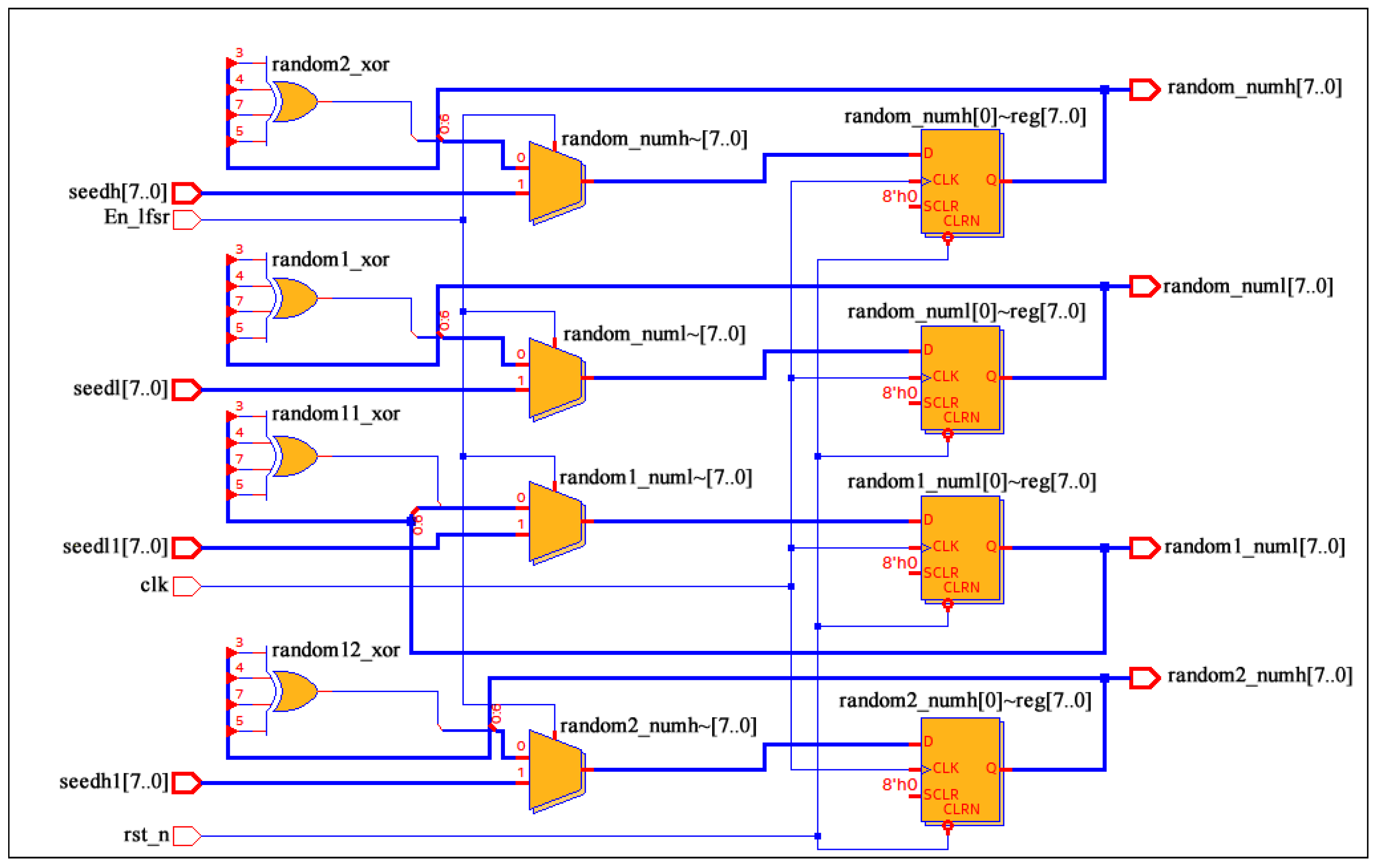
4.1. Random Number Generator Module

According to the principles of the LDSBAS algorithm, the first step involves the generation of random vectors for the movement and evolution directions of the beetles. As this paper primarily optimizes the P and I parameters of the PI controller, the environment for beetle activity is set in two dimensions. In contrast to other high-level programming languages where the $random function cannot be directly synthesized into a circuit, this paper employs a linear feedback shift register (LFSR) to generate pseudo-random numbers [32]. To address the requirement for multiple streams of random numbers, this paper has developed a generator capable of producing four streams of LFSR pseudo-random numbers. This generator accomplishes this by performing an XOR operation on the outputs of the 6th, 4th, 3rd, and 2nd bits and feeding the result back to the input. The circuit depicted in Figure 1 is replicated four times, each receiving a different seed, thereby producing a polynomial, as shown in Equation (10).
The seed width is set to 8 bits, and the XOR operation of the 7th, 5th, 4th, and 3rd bits of the output is fed back to the input. The RTL model of the LFSR in Figure 1 complies with the given polynomial. Given four different seeds, the LFSR model generates four different random numbers, as the ‘En_lfsr’ signal is valid.
f ( x ) = x 8 + x 6 + x 5 + x 4 + 1

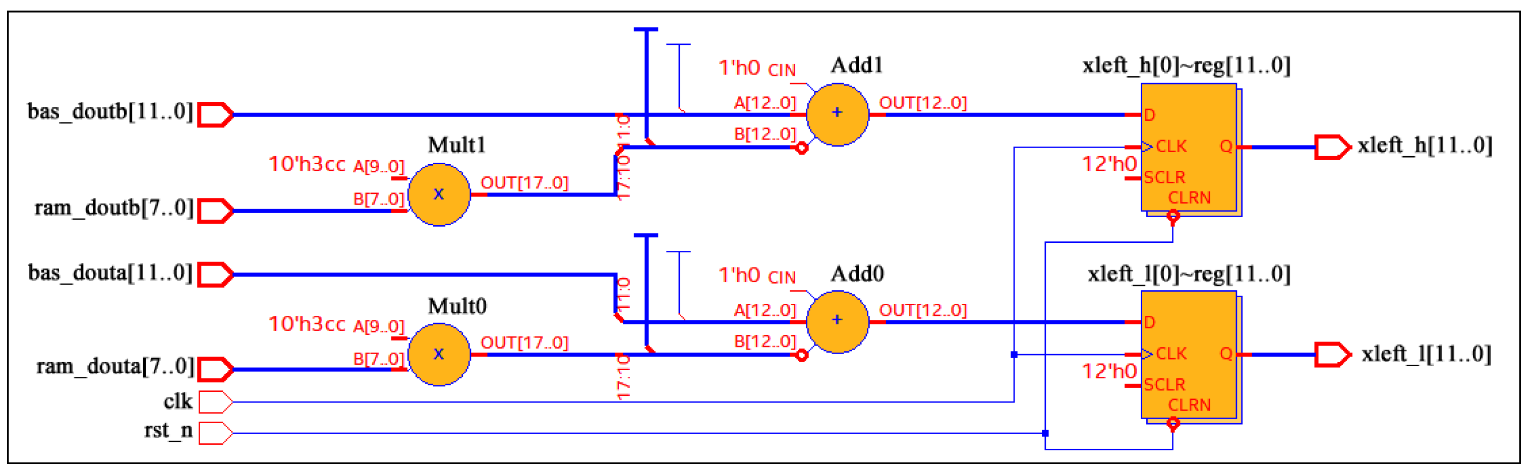
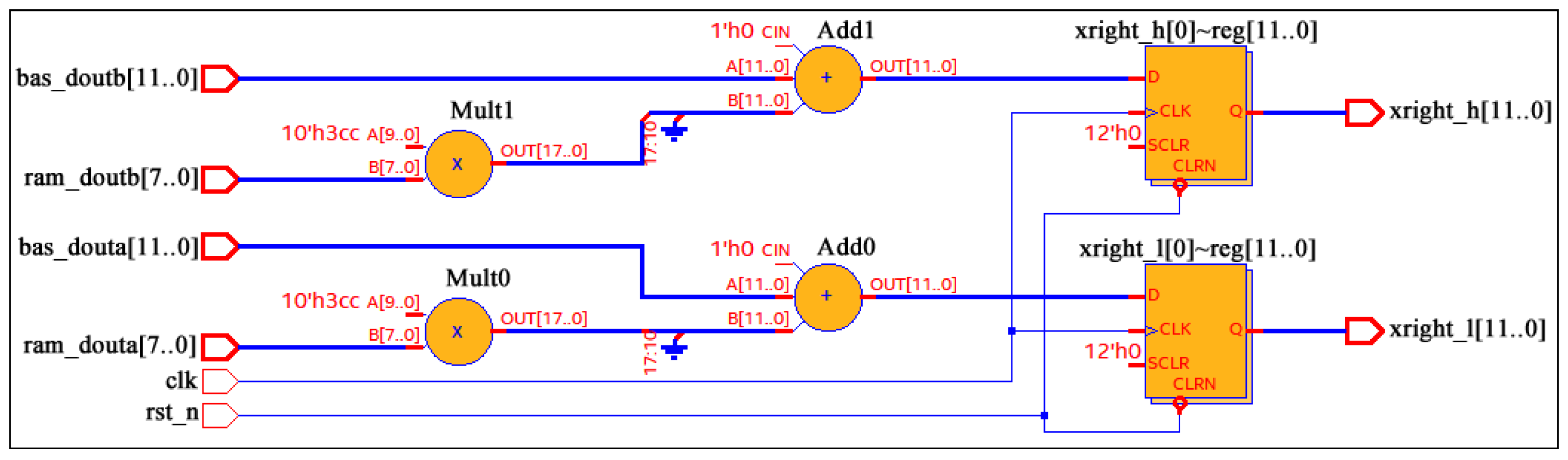
4.2. Antenna Update Module

The method for calculating the coordinates of the beetle’s antennae indicates that the updates of the two antennae are related to the detection distance ‘ d t ’, which is set to 0.95 according to Ref. [11]. However, floating-point numbers cannot be directly computed in the Verilog hardware description language. We use fixed-point arithmetic [33,34] to solve the floating-point number problems in the BAS algorithm. We use Equation (11) to calculate the fixed-point ‘ d t ’.
d t = 0.95 × 2 10 .
In order to use bitwise operations to restore the data in subsequent calculations, we multiply the floating-point number by 2 to the power of 10 in Equation (11). The RTL models for the updated antennae are shown in Figure 2 and Figure 3. The Ram outputs ‘ram_douta’ and ‘ram_doutb’ are two sets of random numbers read from the Ram. ‘Bas_douta’ and ‘bas_doutb’ represent the position coordinates of the beetle. ‘Xleft_h’ and ‘xleft_l’ are the two-dimensional coordinates of the current left antenna, and ‘xright_h’ and ‘xright_l’ are the two-dimensional coordinates of the current right antenna. Finally, the two-dimensional coordinates of the left and right antennae are sent to the fitness function module to calculate the fitness function values for these two antennae.

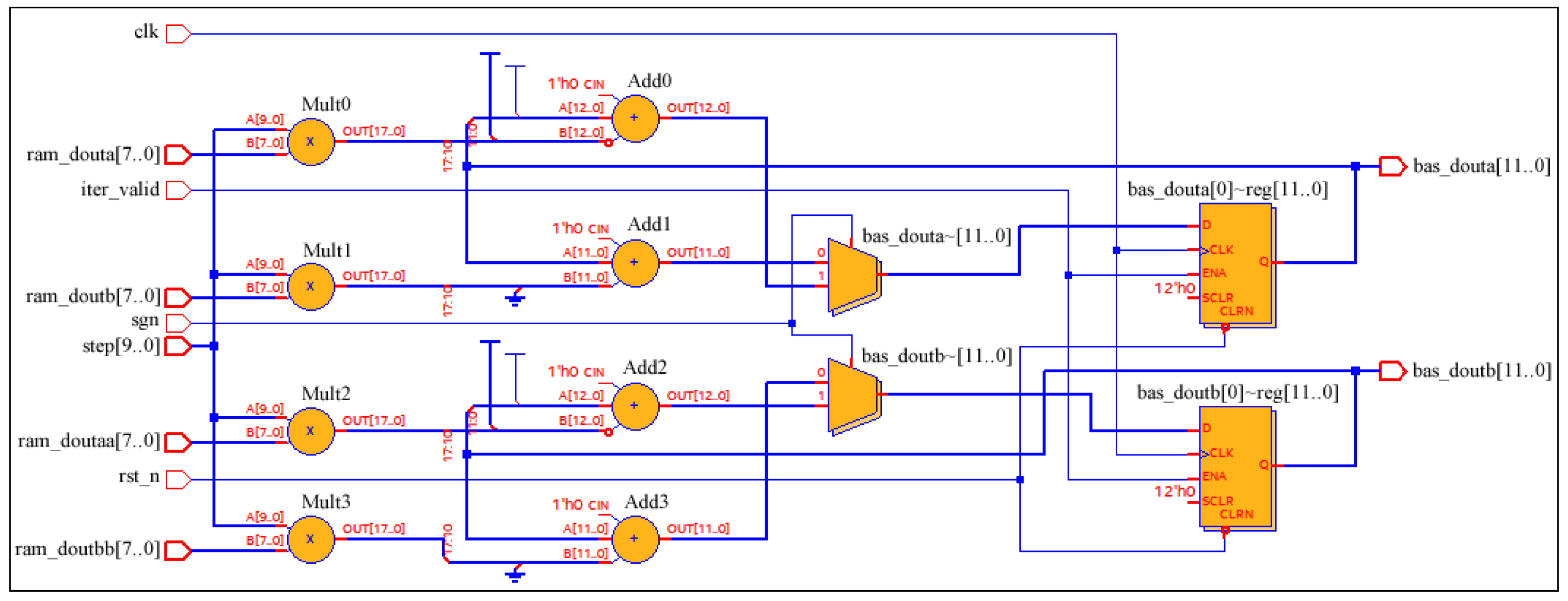
4.3. Position Update Module

After multiple experiments, it was found that the PI controller works best when the maximum number of iterations iter max in Equation (8) is set to 200, the minimum step size step min is set to 0.4, and the maximum step size step max is set to 0.8. The step size update is given by
step t = 0.8 0.004 t .
The floating-point numbers in the step size formula are also enlarged by 1024 times and fixed-pointed as follows:
step t = 819 4 t .
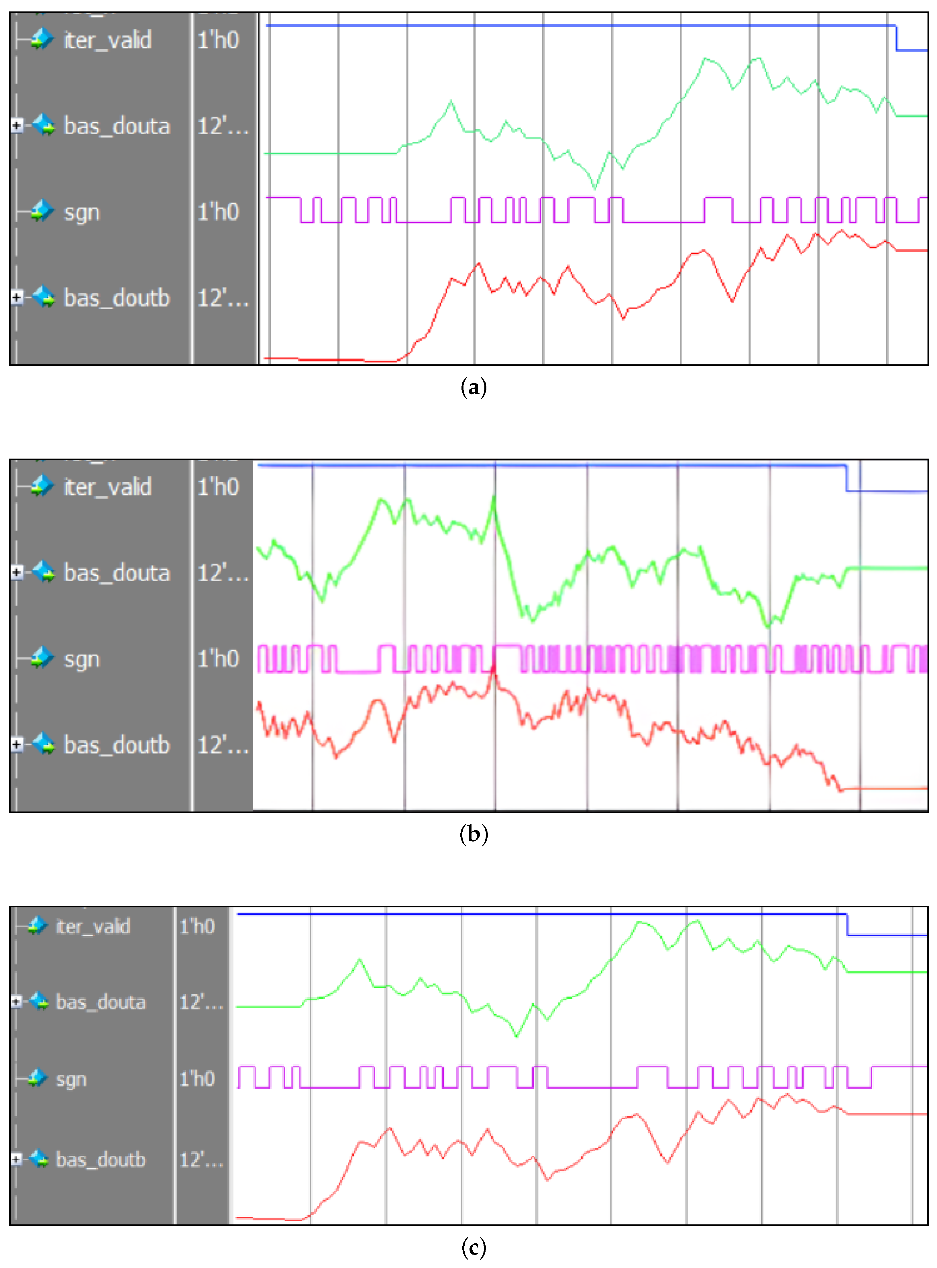
During the position update process of the beetle, the sign function determines which direction the beetle moves toward. ‘xleft_fitness’ and ‘xright_fitness’ represent the fitness values of the left and right antennae, respectively. The sign function in Verilog is represented as follows:
sgn = ( xleft _ fitness > xright _ fitness ) ? 1 b 1 : 1 b 0 .
According to the meaning of the sign function, a sign function value of ‘1’ indicates a beetle moving forward, ‘−1’ indicates moving backward, and ‘0’ indicates no movement. Unlike in other programming languages, in Verilog, a sign function value of ‘1’ indicates movement forward, ‘0’ indicates movement backward, and the D flip-flop maintains its current value when the beetle is still.
Figure 4 shows the RTL model for updating the position of the beetle. When ‘iter_valid’ is low, it indicates that the beetle has found food at the end of the iteration. ‘Bas_douta’ and ‘bas_doutb’ represent the current coordinates of the beetle’s location, while ‘ram_doutaa’ and ‘ram_doutbb’ are two different random numbers of RAM.

4.4. Fitness Function Calculation Module

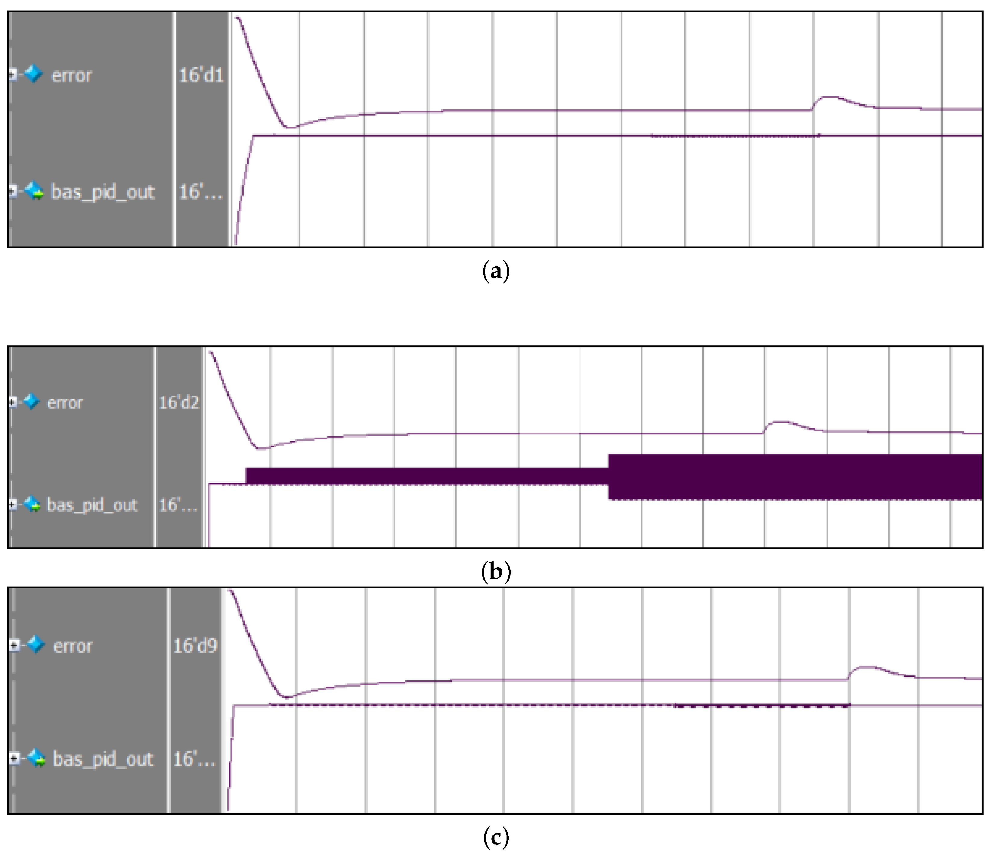
In the design of the LDSBAS algorithm, computing the fitness function is critical not only for the algorithm speed but also for minimal logic resource consumption during FPGA implementation. The fitness function calculation needs to be optimized to reduce the computational burden and save logic resources during FPGA implementation.
The ITAE is further written in discrete form:
ITAE = k = 0 m k T 2 e r r o r ( k ) ,
where k is the number of sampling points, and T is the sampling period.
Once the sampling period is determined, T 2 is a constant whose existence does not affect the performance of the PMSM control system. Therefore, the ITAE can be calculated on the FPGA according to the following equation:
ITAE = k = 0 m k e r r o r ( k ) .
This section introduces the hardware description of the LDSBAS algorithm. We will now turn our attention to investigating the PMSM control algorithm.

5. The PMSM Control System Based on the LDSBAS Algorithm

5.1. PI Controller Module

The PMSM control system uses a PI controller to regulate the current of the motor. This ensures the precise control of the speed and position of the motor. We use the following continuous form of the PI controller:
u ( t ) = k p e ( t ) + k i 0 t e ( t ) d t ,
where k p is the proportional parameter, k i is the integral parameter, u ( t ) is the output of the PI control signal, and e ( t ) is the system error signal.
To implement a PI controller on an FPGA, it is necessary to transform the continuous form of the PI controller into a digital form. Taking the Z-transform of Equation (17), we have
U ( z ) ( 1 z 1 ) = ( k i + k p ) E ( z ) k p z 1 E ( z ) .
In order to implement a digital PI controller on an FPGA, we let k 1 = k p + k i and k 2 = k p , and then we obtain the inverse Z-transform of Equation (18) as follows:
u ( k ) = u ( k 1 ) + k 1 e ( k ) k 2 e ( k 1 ) .

5.2. Coordinate Transform Module

A coordinate transformation can convert three-phase AC signals to relatively stationary two-phase signals and vice versa. This transformation facilitates more precise and efficient motor control. This paper mainly uses four coordinate transformations: inverse Park transformation, inverse Clark transformation, Park transformation, and Clark transformation.

5.2.1. Inverse Park Transformation

The inverse Park transform plays a crucial role in PMSM control systems by converting control signals from the d - q coordinate system back to the a - b - c coordinate system. This enables the controller to generate actual usable motor control signals for the motor. The inverse Park transformation is expressed as follows:
u α u β = cos θ sin θ sin θ cos θ u d u q ,
where u d and u q are the voltages in the d-q coordinate system, and θ is the rotation angle of the rotor.

5.2.2. Inverse Clark Transformation

After applying the inverse Park transform, the voltage values u α and u β are obtained and are then transformed into the three-phase voltage values u a , u b , and u c . We utilize the obtained three-phase voltage values as inputs for the SVPWM algorithm to eliminate the irrational factor that exists in SVPWM algorithms. Thus, it is more easily implemented on an FPGA platform for the SVPWM algorithm.
u a u b u c = 1 0 1 2 3 2 1 2 3 2 u α u β ,
where u α and u β are the voltages in the α - β coordinate system.

5.2.3. Clark Transformation

The purpose of the Clark transformation is to convert the three-phase AC motor’s current signals into two independent axes (vertical and horizontal axes) current signals. This is a necessary step before performing the Park transform. The Clark transformation is expressed as follows:
i α i β = 2 3 1 1 2 1 2 0 3 2 3 2 i a i b i c ,
where i α and i β are the currents in the α - β coordinate system of the motor, and i a , i b , and i c are the collected motor currents.

5.2.4. Park Transformation

The Park transformation converts current signals on the vertical and horizontal axes into current and flux control signals for the DC motor. This enables the controller to control the direction and magnitude of the motor’s magnetic field, thereby controlling the motor’s torque and speed. The Park transformation is expressed as follows:
i d i q = cos θ sin θ sin θ cos θ i a i β ,
where i d and i q are currents in the d - q frame.

5.3. SVPWM Generator Module

The space vector pulse-width modulation (SVPWM) algorithm is a PWM modulation method [35] that can convert three-phase currents into a space vector. The magnitude and direction of the space vector represent the magnitude and phase angle of the current. This algorithm can control the current and torque of the motor by adjusting the size and direction of the space vector. It is also an important method to achieve the high-precision performance of the motor. Figure 5 illustrates the functional block diagram of a three-phase SVPWM generator module.

6. Results Analysis of PMSM Control System Simulation

To comprehensively assess the performance of the LDSBAS algorithm within the PMSM control system, simulations were performed for three cases, namely, no load, speed transient, and load transients, which can lead to changes in motor parameters. Throughout these simulations, the performance of the PI controller, BAS-algorithm-based speed controller, and LDSBAS-algorithm-based speed controller was compared. This paper aimed to further substantiate the advantages of the LDSBAS algorithm by contrasting simulations across different scenarios. 
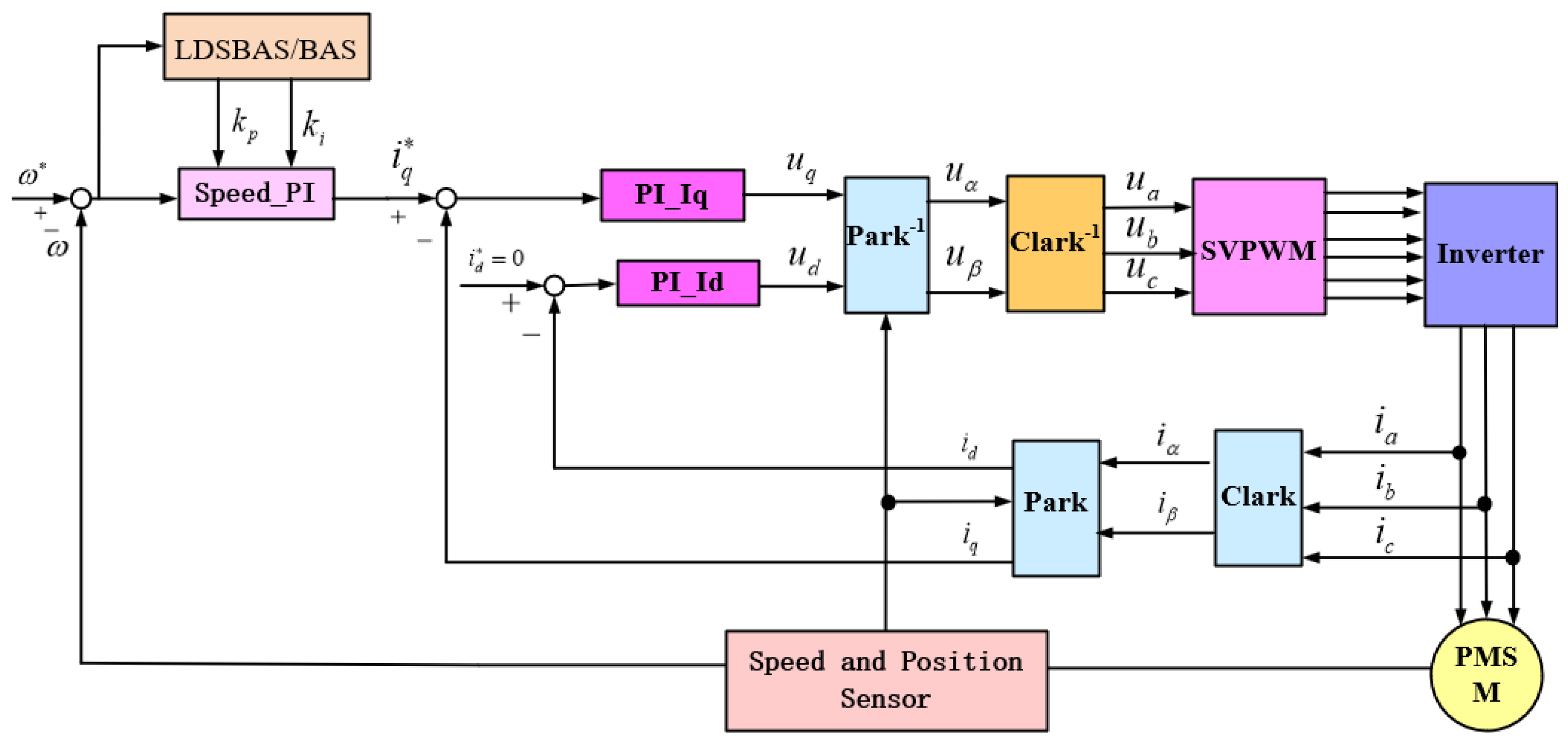
Figure 6 illustrates a schematic diagram of the PMSM control system based on the LDSBAS algorithm. To calculate the parameters of the PI controller, the parameters of the PMSM in the simulation are given in Table 1. According to [36,37], we obtain k p = 0.14 and k i = 7 by utilizing the parameters in Table 1 and Equation (24) as follows:
k p = α J 1.5 P n ψ f , k i = α k p ,
where α represents the speed loop bandwidth, P n represents the number of motor poles, ψ f represents the flux linkage, and J represents rotational inertia.
Table 2 provides the parameters of different controllers. The parameters of the BAS/ LDSBAS-PI controller are adjustable. Their initial ranges are determined based on the parameters of the PI controller. Then, according to the performance of the PMSM control system under three different disturbance conditions, we further provide the upper and lower bounds of the parameter variations.

6.1. No Load

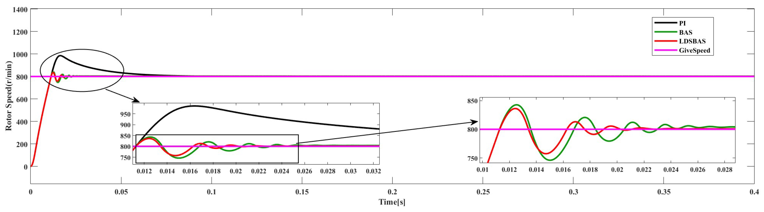
Figure 7 shows the simulation results under no-load conditions at a given speed of 800 r/min. The output of the PI controller exhibits a significant overshoot, surpassing 150 r/min as the maximum. In contrast, both the BAS-algorithm- and LDSBAS-algorithm-based speed controllers demonstrate notably reduced overshoots, each with a maximum of less than 50 r/min. By 0.025 s, the speed controllers of both optimization algorithms have reached the target speed, while the PI controller starts approaching it gradually at the same time. Clearly, these two algorithms significantly expedite the motor’s response speed. At around 0.02 s, the LDSBAS algorithm has already reached the target speed with a smaller error, indicating its enhanced motor response speed. Analyzing the simulation results of the PI controller, BAS-algorithm-based speed controller, and LDSBAS-algorithm-based speed controller confirms that the LDSBAS algorithm effectively reduces the overshoot in the PI controller’s output while enhancing the response speed of the PMSM control system.

6.2. Speed Transient

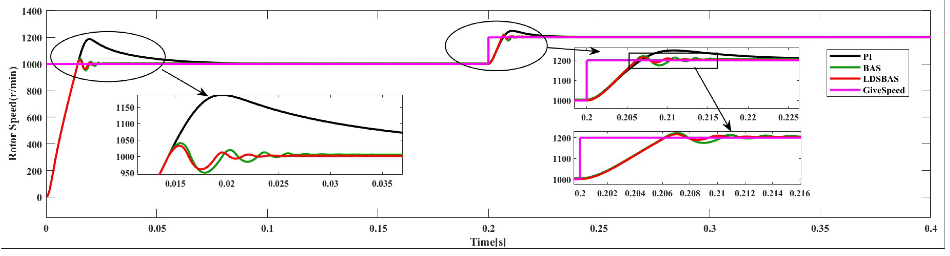
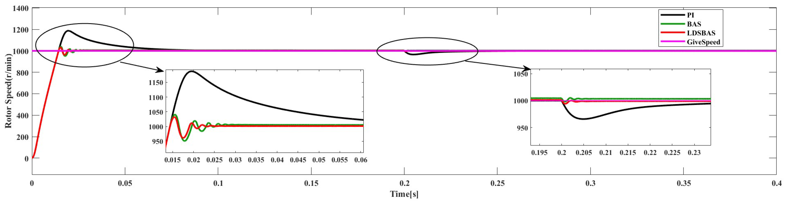
Figure 8 depicts the simulation results with speed transient variation without a load. Initially set at 1000 r/min, the speed abruptly changed to 1200 r/min at 0.2 s. The speed error indicated that the PI controller output had an overshoot exceeding 150 r/min. Conversely, both the BAS- and LDSBAS-algorithm-based speed controllers exhibited notably reduced overshoots. The LDSBAS-algorithm-based controller reached the target speed by 0.02 s, while the BAS algorithm required 0.025 s. The LDSBAS-algorithm-based speed controller demonstrated a faster response. At 0.2 s, during the speed change, the PI controller showed the most severe amplitude oscillations, followed by a slight improvement with the BAS algorithm. Comparatively, while the LDSBAS algorithm also exhibited amplitude oscillations, the maximum did not exceed 20 r/min. By 0.22 s, the PI controller was close to the target speed, exhibiting the maximum overshoot. The BAS algorithm approached the target speed at 0.215 s, whereas the LDSBAS algorithm had already done so by 0.21 s. The LDSBAS algorithm provided a system with a smaller overshoot and faster response during sudden speed variations. The comparative simulation results demonstrate that the PMSM control system using the LDSBAS algorithm maintains good stability and a faster response.

6.3. Load Transients

Figure 9 demonstrates the simulation results of the load torque transient from 0 N·m to 5 N·m at 0.2 s when the given speed is 1000 r/min. In this situation, the LDSBAS algorithm’s PI controller still has the smallest overshoot and fastest response time, while the PI controller still has the largest overshoot and takes 0.23 s to gradually approach the target speed. At 0.21 s, both the LDSBAS and BAS algorithms reach the target speed, but the BAS algorithm has a smaller error. Therefore, in dealing with the load torque transient of the PMSM control system, the LDSBAS algorithm performs better than the PI and the BAS algorithm.
Through simulations under three different scenarios, it can be observed that, compared to the traditional PI and BAS-based PI controllers, the LDSBAS-PI controller minimizes the overshoot and improves the motor response speed against load disturbances to some extent. Furthermore, the LDSBAS algorithm exhibits an inevitable overshoot and oscillations in the speed response curve during motor startup or in the presence of external forces. However, compared to PI control, the magnitude of the overshoot is much smaller, and the duration of oscillations is much shorter. Especially when external disturbances occur, the disturbance rejection capability of the LDSBAS algorithm is superior to PI control. This validates the effectiveness of the LDSBAS algorithm.

7. FPGA-Based PMSM Control System

Based on the structure of the PMSM control system in Figure 6, an approach based on a top-down design philosophy was implemented on an FPGA. The register transfer level design of each module is first described, followed by a description of closed-loop simulations conducted on the Modelsim simulation platform. Finally, the entire control system is evaluated for resources on multiple FPGA platforms.

7.1. Hardware Simulation of PMSM Control System

When implementing the PMSM control system on the FPGA, various crucial factors were primarily considered in this study. First, the design incorporated rational timing sequences to ensure that signal arrival and response times aligned with control requirements. Second, to ensure the accuracy of the hardware design, the efficient utilization of hardware resources and adherence to clock frequency limitations were taken into account. Lastly, hardware simulation scripts were developed to verify whether the functionality and timing of each module met the necessary criteria. Considering these factors, a testbench simulation script was written to validate the feasibility of the PMSM control system based on the LDSBAS algorithm in the FPGA implementation.
Figure 10a–c illustrate the simulation results of the beetle position update module for various iteration counts. When “iter_valid” was at a low logic level, indicating the completion of iterations, it indicated that the beetle had located food. Observations from Figure 10a–c reveal that when “sgn” equaled 1, the coordinate value decreased, while it increased when “sgn” equaled 0, aligning with the foraging behavior of beetles. Additionally, the beetle’s final position coordinates gradually stabilized, matching the implications of Equation (7). Hence, these outcomes substantiate the correct functionality of the beetle position updating module.
Figure 11a–c depict the simulation results of the PI controller outputs for 200, 100, and 50 iterations. Figure 11 shows the different levels of fluctuations corresponding to different iteration counts. Notably, at 100 iterations, the output waveform of the motor’s PI controller exhibits pronounced oscillations. As the iteration count is reduced to 50, there is a slight improvement in the oscillatory behavior. However, at the 200-iteration point, the PI controller’s output demonstrates the best performance. Given the presence of noise during the actual motor operation, it is reasonable for the speed controller’s output waveform to exhibit a certain degree of fluctuation. This can be minimized but not entirely eliminated. This observation aligns with real motor operation scenarios.
Considering the previous experiments on the PI controller, which had the best performance when there were 200 iterations, we chose an iteration number of 200 for the following closed-loop simulation of the control system.
Figure 12 depicts the results of the closed-loop test. The three duty cycles of all saddle waves are consistent with the theory, which indicates that the closed-loop simulation of the PMSM control system based on the LDSBAS algorithm is valid.
The simulation results indicate that each module of the PMSM control system based on the LDSBAS algorithm is correct, and the implemented hardware solution is feasible. Hardware resource evaluation is pivotal, especially for logic units, storage units, and clock resources.

7.2. FPGA Resource Evaluation

To evaluate the resource consumption of the PMSM control system, this study utilized Intel’s Quartus Prime 18.1 software and Xilinx’s Vivado 2019.2. The Intel device model EP4CE10F17C and the Xilinx device model Zynq series xc7z020clg400-1 were utilized for separate synthesis and layout processes, both operating at a clock frequency of 50 MHz. Table 3 and Table 4 illustrate the hardware resource consumption, indicating that operations involved in coordinate transformation and the LDSBAS algorithm necessitate multiple multiplications, resulting in excessive resource consumption in this area. The consumption rates for Intel (Multiplier) and Xilinx (DSP) series FPGAs stood at 39.13% and 7.13%, respectively. This discrepancy arises from Xilinx having a greater number of multiplier resources, approximately 4.7 times more than Intel, thereby resulting in a lower utilization rate of its multipliers. Through this analysis, this study determined that Intel (LE) series FPGAs occupied approximately 22.55% of logic resources, whereas Xilinx (LUT) series FPGAs consumed only 9.57%. This disparity in resource consumption stems from the differing structures of the two FPGA architectures. Additionally, the Xilinx series FPGA consumed a small portion of FF (3.95%) and BUFG (3.13%). Despite the additional hardware resources consumed during the design process, the utilization of an RTL design scheme throughout the entire system allows for the direct description of the underlying circuits, enhancing flexibility in design and meeting the demands to add functionalities at any time.

8. Conclusions

In this paper, we study the PMSM control system and tackle problems in the speed control strategy. The LDSBAS algorithm is proposed, and a speed control strategy is established. The combination of the LDSBAS algorithm and the PMSM control system was implemented on an FPGA platform, and the consumption of hardware resources was evaluated. Firstly, the proposed LDSBAS algorithm strengthens the beetle’s global and local search competence. Secondly, the LDSBAS algorithm enables adjustable parameters of the PI controller within a certain range. Applied to the PMSM speed control system, the simulation results demonstrate that when the system is subjected to external disturbances, the LDSBAS-PI control strategy exhibits superior performance by minimizing the overshoot and improving the motor response speed. Finally, an LFSR model capable of generating four random numbers is developed on an FPGA platform, and the LFSR model is utilized to implement the hardware design of a PMSM control system based on the LDSBAS algorithm. According to resource evaluation on various FPGA platforms, the intelligent optimization algorithms that we propose present a more feasible solution. In our future work, we intend to investigate the implementation of the BAS algorithm through a software–hardware co-design methodology. Our objective is to meticulously adjust the proportional and integral parameters of the current loop within PMSM control systems. At the same time, we will further investigate the algorithm to make it applicable to motors with unique characteristics.

Author Contributions

Conceptualization, C.W. and K.Z.; methodology, K.Z.; software, C.W.; validation, X.Z.; formal analysis, K.Z.; investigation, C.W.; resources, K.Z.; data curation, K.Z.; writing—original draft preparation, K.Z.; writing—review and editing, C.W.; visualization, C.W.; supervision, X.Z.; project administration, K.Z.; funding acquisition, C.W. and X.Z. All authors have read and agreed to the published version of the manuscript.

Funding

This work was supported by Basic Research Projects of Liaoning Provincial Department of Education of China (JYTMS20230207 and LG202107).

Data Availability Statement

Data are contained within the article.

Conflicts of Interest

The authors declare no conflicts of interest.

References

  1. Liu, J.; Yang, J.; Li, S.; Wang, X. Single-Loop Robust Model Predictive Speed Regulation of PMSM Based on Exogenous Signal Preview. IEEE Trans. Ind. Electron. 2023, 70, 12719–12729. [Google Scholar] [CrossRef]
  2. Wang, Y.; Yu, H.; Liu, Y. Speed-Current Single-Loop Control with Overcurrent Protection for PMSM Based on Time-Varying Nonlinear Disturbance Observer. IEEE Trans. Ind. Electron. 2022, 69, 179–189. [Google Scholar] [CrossRef]
  3. Li, Z.; Yang, X.; Zhao, S. Flux Linkage Observation Using an Improved MRAS Observer in Case of Uniform Demagnetization of IPMSM. IEEE Trans. Instrum. Meas. 2024, 73, 1–10. [Google Scholar] [CrossRef]
  4. Fuentes, E.; Silva, C.A.; Kennel, R.M. MPC Implementation of a Quasi-Time-Optimal Speed Control for a PMSM Drive, with Inner Modulated-FS-MPC Torque Control. IEEE Trans. Ind. Electron. 2016, 63, 3897–3905. [Google Scholar] [CrossRef]
  5. Sel, A.; Sel, B.; Coskun, U.; Kasnakoglu, C. Comparative Study of an EKF-Based Parameter Estimation and a Nonlinear Optimization-Based Estimation on PMSM System Identification. Energies 2021, 14, 6108. [Google Scholar] [CrossRef]
  6. Xie, T.; Xu, X.; Yuan, F.; Song, Y.; Lei, W.; Zhao, R.; Chang, Y.; Wu, X.; Gan, Z.; Zhang, F. Speed Estimation Strategy for Closed-Loop Control of PMSM Based on PSO Optimized KF Series Algorithms. Electronics 2023, 12, 4215. [Google Scholar] [CrossRef]
  7. Chen, H.; Wang, X.; Benbouzid, M.; Charpentier, J.-F.; At-Ahmed, N.; Han, J. Improved Fractional-Order PID Controller of a PMSM-Based Wave Compensation System for Offshore Ship Cranes. J. Mar. Sci. Eng. 2022, 10, 1238. [Google Scholar] [CrossRef]
  8. Baoyong, G.; Zhongjie, Z.; Pan, J.-S.; Chu, S.-C. Optimal Design and Simulation for PID Controller Using Fractional-Order Fish Migration Optimization Algorithm. IEEE Access 2021, 9, 8808–8819. [Google Scholar]
  9. Khudhair, M.; Ragab, M.; AboRas, K.M.; Abbasy, N.H. Robust Control of Frequency Variations for a Multi-Area Power System in Smart Grid Using a Novel Wild Horse Optimized Combination of PIDD2 and PD Controllers. Sustainability 2022, 14, 8223. [Google Scholar] [CrossRef]
  10. Obadina, O.O.; Thaha, M.A.; Althoefer, K.; Shaheed, M.H. Shaheed, Dynamic characterization of a master-slave robotic manipulator using a hybrid grey wolf-whale optimization algorithm. J. Vib. Control 2022, 28, 1992–2003. [Google Scholar] [CrossRef]
  11. Jiang, X.; Li, S. BAS: Beetle Antennae Search Algorithm for Optimization Problems. Int. J. Robot. Control 2017, 1, 1–10. [Google Scholar] [CrossRef]
  12. Gao, B.; Hu, X.; Peng, Z.; Yubo, S. Application of intelligent water drop algorithm in process planning optimization. Int. J. Adv. Manuf. Technol. 2020, 106, 5199–5211. [Google Scholar] [CrossRef]
  13. Zhang, Y.; Li, S.; Xu, B. Convergence analysis of beetle antennae search algorithm and its applications. Soft Comput. 2021, 25, 10595–10608. [Google Scholar] [CrossRef]
  14. Kou, B.; Ren, D.C.; Guo, S.J. Geometric Parameter Identification of Medical Robot Based on Improved Beetle Antennae Search Algorithm. Bioengineering 2022, 9, 58. [Google Scholar] [CrossRef] [PubMed]
  15. Wang, P.; Gao, Y.; Wu, M.; Zhang, F.; Li, G. In-Field Calibration of Triaxial Accelerometer Based on Beetle Swarm Antenna Search Algorithm. Sensors 2020, 20, 4947. [Google Scholar] [CrossRef] [PubMed]
  16. Deng, M.; Yang, Q.; Peng, Y. A Real-Time Path Planning Method for Urban Low-Altitude Logistics UAVs. Sensors 2023, 23, 7472. [Google Scholar] [CrossRef] [PubMed]
  17. Simos, T.E.; Mourtas, S.D.; Katsikis, V.N. Time-varying Black–Litterman portfolio optimization using a bio-inspired approach and neuronets. Appl. Soft Comput. 2021, 112, 107767. [Google Scholar] [CrossRef]
  18. Jiang, X.; Lin, Z.; Li, S.; Ji, Y.; Luan, Y.; Ma, S. Dynamical attitude configuration with wearable wireless body sensor networks through beetle antennae search strategy. Measurement 2021, 167, 108128. [Google Scholar] [CrossRef]
  19. Zhang, P.; Zhang, J. Lower limb exoskeleton robots’ dynamics parameters identification based on improved beetle swarm optimization algorithm. Robotica 2022, 40, 2716–2731. [Google Scholar] [CrossRef]
  20. Lin, M.; Li, Q.; Wang, F.; Chen, D. An improved beetle antennae search algorithm and its application on economic load distribution of power system. IEEE Access 2020, 8, 99624–99632. [Google Scholar] [CrossRef]
  21. Lojda, J.; Panek, R.; Sekanina, L.; Lukas, S.; Zdenek, K. Automated design and usage of the Fault-Tolerant dynamic partial reconfiguration controller for FPGAs. Microelectron. Reliab. 2023, 144, 114976. [Google Scholar] [CrossRef]
  22. Lin, J.; Wu, X. Optimized design and realization of storage array based on FPGA. Dianzi Jishu Yingyong 2023, 49, 111–116. [Google Scholar]
  23. Kumar, S.; Mahapatra, R.; Singh, A. Automatic Modulation Recognition: An FPGA Implementation. IEEE Commun. Lett. 2022, 9, 2062–2066. [Google Scholar] [CrossRef]
  24. Sun, A.; Qin, X. Multichannel ARINC429 bus test system based on FPGA. Dianzi Jishu Yingyong 2023, 49, 119–123. [Google Scholar]
  25. Sai, S.V.; Zinkevich, A.V. Computational methods to increase the speed of FPGA-based discrete wavelet transforms. Naučno-Teh. Vestn. Inf. Technol. 2023, 23, 79–87. [Google Scholar] [CrossRef]
  26. Yue, Z.; Li, G.; Jiang, X.; Li, S.; Cheng, J.; Ren, P. A Hardware Descriptive Approach to Beetle Antennae Search. IEEE Access 2020, 8, 89059–89070. [Google Scholar] [CrossRef]
  27. Damodaram, D.; Venkateswarlu, T. FPGA implementation of genetic algorithm to detect optimal user by cooperative spectrum sensing. ICT Express 2019, 5, 245–249. [Google Scholar] [CrossRef]
  28. Jdidia, S.B.; Belghith, F.; Sallem, A.; Maher, J.; Nouri, M. Hardware implementation of PSO-based approximate DST transform for VVC standard. J. Real-Time Image Process. 2022, 19, 87–101. [Google Scholar] [CrossRef]
  29. Issa, H.H.; Ahmed, S.M.E. FPGA Implementation of Floating Point Based Cuckoo Search Algorithm. IEEE Access 2019, 70, 134434–134447. [Google Scholar] [CrossRef]
  30. Ghith, E.S.; Tolba, F.A.A. Tuning PID Controllers Based on Hybrid Arithmetic Optimization Algorithm and Artificial Gorilla Troop Optimization for Micro-Robotics Systems. IEEE Access 2023, 11, 27138–27154. [Google Scholar] [CrossRef]
  31. Nie, Z.; Wang, Q.; Liu, R.; Lan, Y. Identification and PID control for a class of delay fractional-order systems. IEEE/CAA J. Autom. Sin. 2016, 3, 463–476. [Google Scholar] [CrossRef]
  32. Sadhika, P.; Thuraka, E.R.; Rao, R. Reduced complexity XOR trees for LDPC codes and BS-LFSR techniques to High-Speed memory applications. AEU Int. J. Electron. Commun. 2023, 169, 154754. [Google Scholar] [CrossRef]
  33. Zhao, W.; Dang, Q.; Xia, T.; Zhang, J.; Zheng, N.; Ren, P. Optimizing FPGA-Based DNN Accelerator with Shared Exponential Floating-Point Format. IEEE Trans. Circuits Syst. I Regul. Pap. 2023, 70, 4478–4491. [Google Scholar] [CrossRef]
  34. Qian, W.; Chen, K.; Liu, W.; Cheng, Z. LMM: A Fixed-Point Linear Mapping Based Approximate Multiplier for IoT. J. Comput. Sci. Technol. 2023, 38, 298–308. [Google Scholar]
  35. Liu, Z.; Li, B.; Wang, X.; Xiang, W.; Fei, L. A predictive control method for switching sequence selection based on SVPWM for five-level converter. IET Power Electron. 2023, 16, 990–1000. [Google Scholar] [CrossRef]
  36. Yuan, L.; Shen, J.Q.; Xiao, F.; Chen, M.-L. Nonsingular terminal sliding-mode observer design for interior permanent magnet synchronous motor drive at very low-speed. Acta Phys. Sin. 2013, 62, 030501. [Google Scholar] [CrossRef]
  37. Yuan, L. Modern Permanent Magnet Synchronous Motor Control Principle and MATLAB Simulation; Beihang University Press: Beijing, China, 2016. (In Chinese) [Google Scholar]
Figure 1. RTL model of four pseudo-random numbers from LFSR.
Energies 17 01870 g001
Figure 2. RTL model of right antenna update.
Energies 17 01870 g002
Figure 3. RTL model of right antenna update.
Energies 17 01870 g003
Figure 4. RTL model of beetle position update.
Energies 17 01870 g004
Figure 5. Three-phase SVPWM generator module.
Energies 17 01870 g005
Figure 6. Block diagram of PMSM control system based on LDSBAS/BAS algorithm.
Energies 17 01870 g006
Figure 7. Simulation results of speed response with no load.
Energies 17 01870 g007
Figure 8. Simulation results of speed response with speed transient.
Energies 17 01870 g008
Figure 9. Simulation results of speed response with load transients.
Energies 17 01870 g009
Figure 10. The position update results of the beetle with different numbers of iterations. (a) Simulation of beetle position with 200 iterations; (b) simulation results of beetle position with 100 iterations; (c) simulation results of beetle position with 50 iterations.
Energies 17 01870 g010
Figure 11. The simulation results for the PI controller with different numbers of iterations. (a) The output waveform of the PI controller with a speed loop with 200 iterations; (b) the output waveform of the PI controller with a speed loop with 100 iterations; (c) the output waveform of the PI controller with a speed loop with 50 iterations.
Energies 17 01870 g011
Figure 12. Closed-loop simulation results of PMSM control system.
Energies 17 01870 g012
Table 1. Parameters of PMSM in simulation.
DescriptionValueUnit
Rated speed ( n r a t e d )3000r/min
Number of poles ( P n )4-
Rated resistance ( R s )0.958 Ω
d -axis inductance ( L d )5.25mH
q -axis inductance ( L q )12mH
Flux linkage ( ψ f )0.1827Wb
Rotational inertia (J)0.003kg·m2
Speed loop bandwidth ( α )50Hz
Table 2. Parameters of different controllers.
DescriptionNameValue
BAS s t e p t 0.8
LDSBAS/BAS d t 0.95
LDSBAS/BAS r t [0    1]
LDSBAS i t e r m a x 200
LDSBAS s t e p m a x 0.8
LDSBAS s t e p m i n 0.4
PI k p 0.14
PI k i 7
BAS-PI k p [0.001    3]
BAS-PI k i [0.001    10]
LDSBAS-PI k p [0.001    3]
LDSBAS-PI k i [0.001    10]
Table 3. Intel FPGA resource consumption.
ResourceUtilizationAvailabilityPercent
LE232710,32022.55
Multiplie184639.13
Table 4. Xilinx FPGA resource consumption.
ResourceUtilizationAvailabilityPercent
LUT168517,6009.57
FF139135,2003.95
DSP178021.25
BUFG1323.13
Disclaimer/Publisher’s Note: The statements, opinions and data contained in all publications are solely those of the individual author(s) and contributor(s) and not of MDPI and/or the editor(s). MDPI and/or the editor(s) disclaim responsibility for any injury to people or property resulting from any ideas, methods, instructions or products referred to in the content.

