
Comparative Analysis of Energy Efficiency in High-Voltage Ozone Generators: Resonant Versus Non-Resonant Systems †


Abstract
1. Introduction
2. Materials and Methods
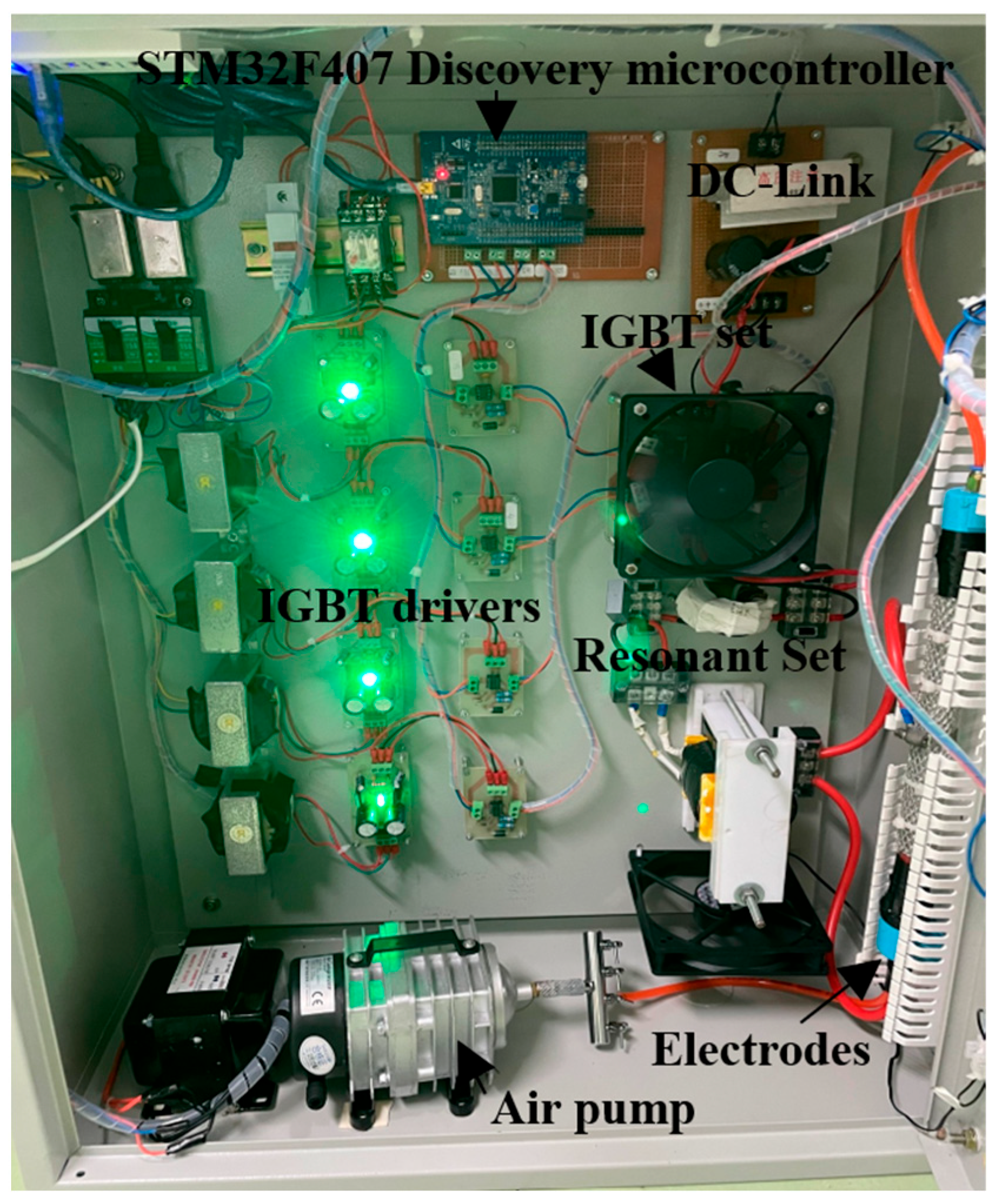
2.1. Power Frequency Converter
2.2. High-Frequency High-Voltage Transformer
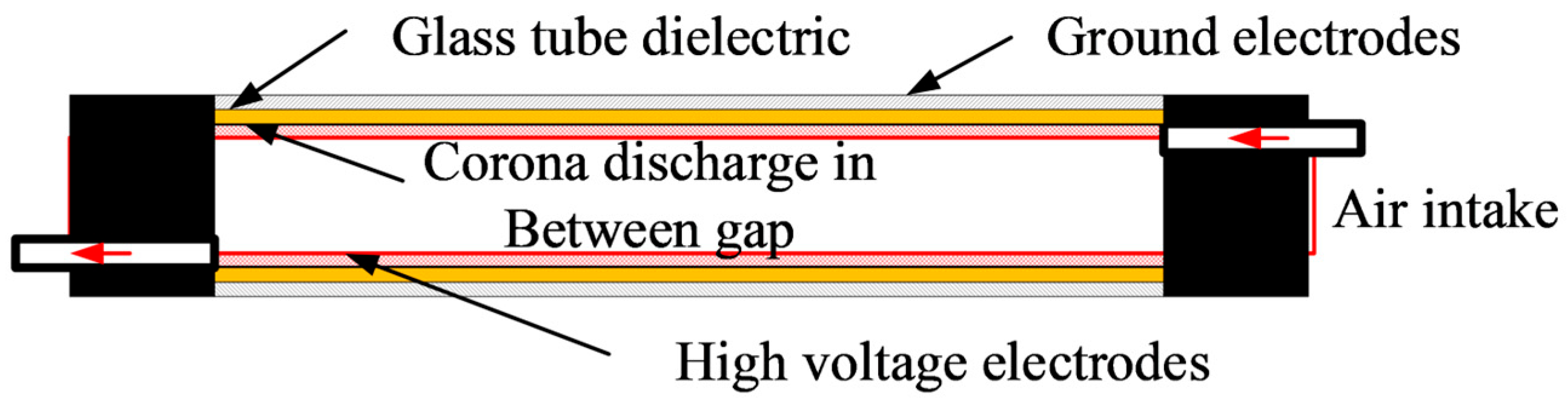
2.3. Ozone Generation
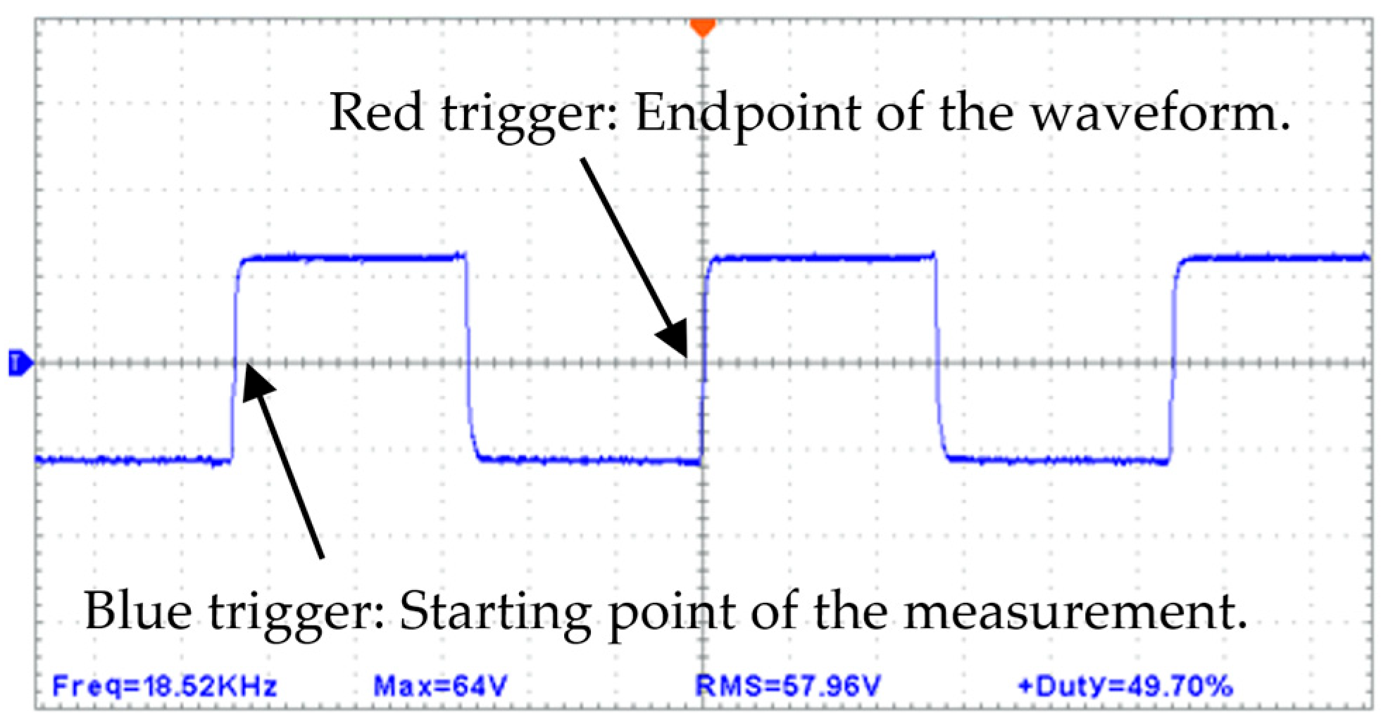
3. Results and Discussion
3.1. Power Frequency Converter with Non-Resonant Systems in an Ozone Generator
3.2. Power Frequency Converter with Resonant Systems in an Ozone Generator
4. Discussion
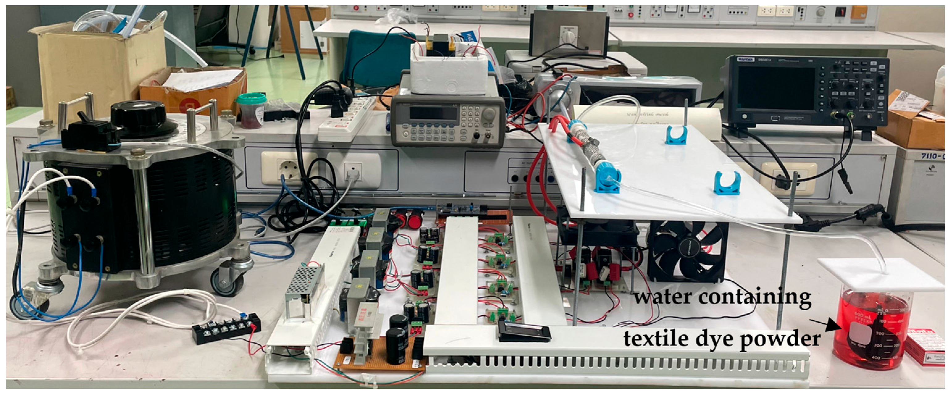
4.1. Resonant Systems in an Ozone Generator Test with Wastewater
4.2. Safety and Environmental Conditions in an Ozone Generator Test with Wastewater
5. Conclusions
Author Contributions
Funding
Data Availability Statement
Acknowledgments
Conflicts of Interest
References
- Liao, R.J.; Yang, L.J.; Li, J.; Grzybowski, S. Aging Condition Assessment of Transformer Oil-Paper Insulation Model Based on Partial Discharge Analysis. IEEE Trans. Dielectr. Electr. Insul. 2011, 18, 303–311. [Google Scholar] [CrossRef]
- Eliasson, B.; Kogelschatz, U. Modeling and applications of silent discharge plasmas. IEEE Trans. Plasma Sci. 1991, 19, 309–323. [Google Scholar] [CrossRef]
- Yutthagowith, P.; Prombud, T.; Leelachariyakul, B. Development of a resonant frequency converter for partial discharge tests on potential transformers. In Proceedings of the 2018 18th International Conference on Harmonics and Quality of Power (ICHQP), Ljubljana, Slovenia, 13–16 May 2018; pp. 1–5. [Google Scholar] [CrossRef]
- Huiskamp, T.; van Oorschot, J.J.; Pereira, M.T.; Redondo, L.M. Ozone Generation with a Flexible Solid-State Marx Generator. In Proceedings of the 2018 IEEE International Power Modulator and High Voltage Conference (IPMHVC), Jackson, CA, USA, 3–7 June 2018; pp. 147–150. [Google Scholar] [CrossRef]
- Pasupuleti, S.S.; Krishnamoorthy, H.S. Adaptive Pulse Power Converter using MagAmp for Bio-Medical Applications. In Proceedings of the IECON 2024—50th Annual Conference of the IEEE Industrial Electronics Society, Chicago, IL, USA, 3–6 November 2024; pp. 1–6. [Google Scholar] [CrossRef]
- Amri, D.; Fitria, S.; Nawawi, Z.; Kurnia, R.F.; Waringin, T.P.; Dewi, T.; Buntat, Z. Discharge Current Characteristics of Different Electrode Materials for Ozone Generation. In Proceedings of the 2024 International Conference on Electrical Engineering and Computer Science (ICECOS), Palembang, Indonesia, 25–26 September 2024; pp. 430–433. [Google Scholar] [CrossRef]
- Nacéra, H.; Said, N.; Kamel, N.; Amar, T. Realization of a High-Voltage High-Frequency Power Supply for Ozone Generation. Application to Water Traitement. In Proceedings of the 2024 3rd International Conference on Advanced Electrical Engineering (ICAEE), Sidi-Bel-Abbes, Algeria, 5–7 November 2024; pp. 1–7. [Google Scholar] [CrossRef]
- Murdiya, F.; Hamzah, A.; Andrio, D. The Application of Non-Sinusoidal Resonance Inverter on An Ozone Generator. In Proceedings of the 2019 IEEE Conference on Energy Conversion (CENCON), Yogyakarta, Indonesia, 16–17 October 2019; pp. 142–146. [Google Scholar] [CrossRef]
- Chen, F.; Chen, W.; Hu, B. Hybrid LLC and Full Bridge Paralleled Converter With Variable-Frequency Plus Phase-Shift Control for Wide Voltage Gain Range Application. IEEE Access 2025, 13, 1295–1306. [Google Scholar] [CrossRef]
- Abkenar, P.P.; Iman-Eini, H.; Samimi, M.H.; Emaneini, M. Design and Implementation of Ozone Production Power Supply for the Application of Microbial Purification of Water. IEEE Trans. Power Electron. 2020, 35, 8215–8223. [Google Scholar] [CrossRef]
- Kuldip, C.; Lakshminarasamma, N. An Energy-Based Analysis of High Voltage Resonant-Based Pulsed Low Power Converter for Water Treatment Application. IEEE Access 2024, 12, 49429–49448. [Google Scholar] [CrossRef]
- Primas, J.; Malík, M.; Pokorný, P.; Novák, J.; Parma, P.; Sanetrník, F.; Schovanec, P. Detailed Analysis of Airflow Generated by High Voltage on a Point-Tube Electrode Geometry. Fluids 2023, 8, 115. [Google Scholar] [CrossRef]
- Tandon, S.; Rathore, A.K. Current-Fed Full-Bridge Series LC Resonance Impulse ZCS Commutated DC-DC Converter. In Proceedings of the 2020 IEEE International Conference on Power Electronics, Smart Grid and Renewable Energy (PESGRE2020), Cochin, India, 2–4 January 2020; pp. 1–6. [Google Scholar] [CrossRef]
- Aslan, S.; Oktay, U.; Altintas, N. A Novel Non-Resonant Full-Bridge Multi-Output Topology for Domestic Induction Heating Applications. Electronics 2025, 14, 596. [Google Scholar] [CrossRef]
- Tial, M.-S.; Mitsugi, F. Characteristics of Water-Cooling Dielectric Barrier Discharge Spraying Nozzle. IEEE Trans. Plasma Sci. 2022, 50, 2972–2976. [Google Scholar] [CrossRef]
- Hocke, K. Oxygen in the Earth System. Oxygen 2023, 3, 287–299. [Google Scholar] [CrossRef]
- Ikonen, J.; Nuutinen, I.; Niittynen, M.; Hokajärvi, A.M.; Pitkänen, T.; Antikainen, E.; Miettinen, I.T. Presence and Reduction of Anthropogenic Substances with UV Light and Oxidizing Disinfectants in Wastewater—A Case Study at Kuopio, Finland. Water 2021, 13, 360. [Google Scholar] [CrossRef]
- Zoumpouli, G.A.; Baker, R.; Taylor, C.M.; Chippendale, M.J.; Smithers, C.; Ho, S.S.; Wenk, J. A Single Tube Contactor for Testing Membrane Ozonation. Water 2018, 10, 1416. [Google Scholar] [CrossRef]
- Prombud, T.; Wisassakwichai, C.; Anusurain, E.; Methavithit, W. Ozone Treatment Strategies for Efficient Color Removal in Wastewater. In Proceedings of the 2024 12th International Electrical Engineering Congress (iEECON), Hua Hin, Thailand, 6–8 March 2024; pp. 1–4. [Google Scholar] [CrossRef]
- Nassour, K.; Brahami, M.; Nemmich, S.; Hammadi, N.; Tilmatine, A.; Zouzou, N. A new hybrid surface-volume dielectric barrier discharge reactor for ozone generation. In Proceedings of the 2015 IEEE Industry Applications Society Annual Meeting, Addison, TX, USA, 18–22 October 2015; pp. 1–7. [Google Scholar] [CrossRef]
- Cui, H.; Wang, F.; Liang, Z.; Li, K. Current harmonics reduction of square wave inverter by using adjustable filter for high speed motor power supply. In Proceedings of the 2008 International Conference on Electrical Machines and Systems, Wuhan, China, 17–20 October 2008; pp. 954–957. [Google Scholar]
- Albatran, S.; Allabadi, A.S.; Khalaileh, A.-A.; Fu, Y. Improving the Performance of a Two-Level Voltage Source Inverter in the Overmodulation Region Using Adaptive Optimal Third Harmonic Injection Pulsewidth Modulation Schemes. IEEE Trans. Power Electron. 2021, 36, 1092–1103. [Google Scholar] [CrossRef]
- Li, S.; Zhou, S.; Li, H. Harmonic Suppression Strategy of LCL Grid-Connected PV Inverter Based on Adaptive QPR_PC Control. Electronics 2023, 12, 2282. [Google Scholar] [CrossRef]
- Kül, S.; Yildiz, B.; Tamyurek, B.; Iskender, I. Coreloss Estimation via Long Short-Term Memory Model (LSTM) of Dry-Type Transformer based on FEA. In Proceedings of the 2021 10th International Conference on Renewable Energy Research and Application (ICRERA), Ankara, Turkey, 26–29 September 2021; pp. 357–361. [Google Scholar] [CrossRef]
- Zeinali, R.; Ghanizadeh, A.J.; Asl, R.T.; Gharehpetian, G.B. Transformer high frequency modelling based on lumped parameter model by consideration of corelosses. In Proceedings of the 2014 22nd Iranian Conference on Electrical Engineering (ICEE), Tehran, Iran, 20–22 May 2014; pp. 763–767. [Google Scholar] [CrossRef]
- Roger, D.; Napieralska, E.; Komeza, K.; Napieralski, P. Design of High-Power Solid-State Transformers with Grain-Oriented Electrical Steel Cores. Electronics 2022, 11, 2398. [Google Scholar] [CrossRef]


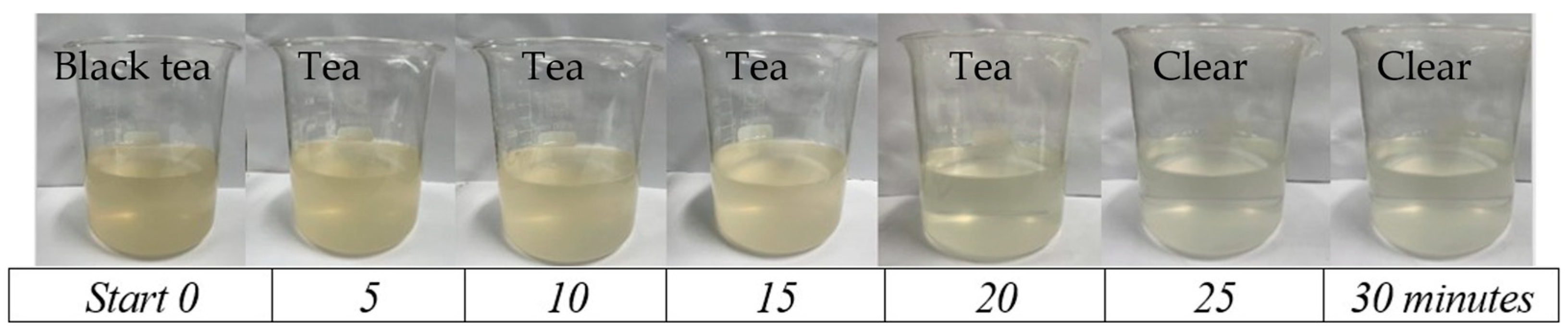
| Parameter | Treatment with Ozone for a Duration of 0–30 min | Quality Std. | ||||||
|---|---|---|---|---|---|---|---|---|
| Sample | 5 | 10 | 15 | 20 | 25 | 30 | ||
| pH | 7.66 | 8.32 | 8.34 | 8.35 | 8.37 | 8.38 | 8.38 | 5–9 |
| DO, mg/L | 2.78 | 6.46 | 6.70 | 6.75 | 6.82 | 6.88 | 6.91 | ≥6 |
| Color | Black tea | Tea | Tea | Tea | Tea | Clear | Clear | Clear |
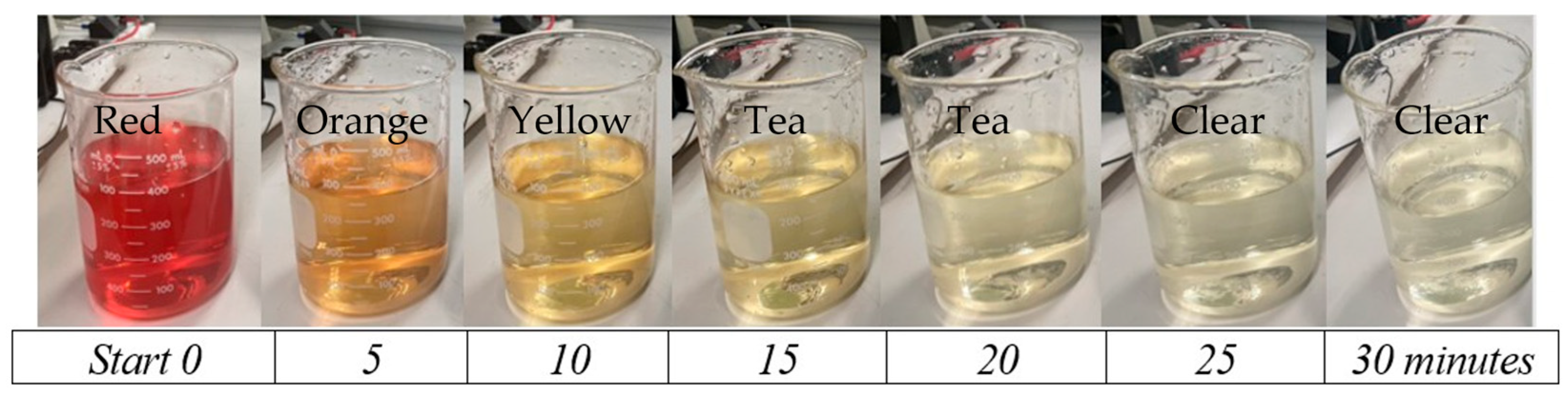
| Parameter | Treatment with Ozone for a Duration of 0–30 min. | Quality Std. | ||||||
|---|---|---|---|---|---|---|---|---|
| Sample | 5 | 10 | 15 | 20 | 25 | 30 | ||
| pH | 7.32 | 8.29 | 8.30 | 8.30 | 8.30 | 8.31 | 8.31 | 5–9 |
| DO, mg/L | 3.65 | 6.15 | 6.22 | 6.29 | 6.38 | 6.44 | 6.50 | ≥6 |
| Color | Black Tea | Tea | Tea | Tea | Clear | Clear | Clear | Clear |
Disclaimer/Publisher’s Note: The statements, opinions and data contained in all publications are solely those of the individual author(s) and contributor(s) and not of MDPI and/or the editor(s). MDPI and/or the editor(s) disclaim responsibility for any injury to people or property resulting from any ideas, methods, instructions or products referred to in the content. |
© 2025 by the authors. Licensee MDPI, Basel, Switzerland. This article is an open access article distributed under the terms and conditions of the Creative Commons Attribution (CC BY) license (https://creativecommons.org/licenses/by/4.0/).
Share and Cite
Prombud, T.; Anusurain, E.; Wisassakwichai, C.; Kamonkhantithorn, C. Comparative Analysis of Energy Efficiency in High-Voltage Ozone Generators: Resonant Versus Non-Resonant Systems. Energies 2025, 18, 2124. https://doi.org/10.3390/en18082124
Prombud T, Anusurain E, Wisassakwichai C, Kamonkhantithorn C. Comparative Analysis of Energy Efficiency in High-Voltage Ozone Generators: Resonant Versus Non-Resonant Systems. Energies. 2025; 18(8):2124. https://doi.org/10.3390/en18082124
Chicago/Turabian StylePrombud, Tongpian, Ekkapol Anusurain, Chainarong Wisassakwichai, and Choosak Kamonkhantithorn. 2025. "Comparative Analysis of Energy Efficiency in High-Voltage Ozone Generators: Resonant Versus Non-Resonant Systems" Energies 18, no. 8: 2124. https://doi.org/10.3390/en18082124
APA StylePrombud, T., Anusurain, E., Wisassakwichai, C., & Kamonkhantithorn, C. (2025). Comparative Analysis of Energy Efficiency in High-Voltage Ozone Generators: Resonant Versus Non-Resonant Systems. Energies, 18(8), 2124. https://doi.org/10.3390/en18082124