Article

Low Resistance TiO2/p-Si Heterojunction for Tandem Solar Cells

by
Steponas Ašmontas
*,
Maksimas Anbinderis
,
Jonas Gradauskas
,
Remigijus Juškėnas
,
Konstantinas Leinartas
,
Andžej Lučun
,
Algirdas Selskis
,
Laurynas Staišiūnas
,
Sandra Stanionytė
,
Algirdas Sužiedėlis
,
Aldis Šilėnas
and
Edmundas Širmulis
Center for Physical Sciences and Technology, Savanorių ave. 231, 02300 Vilnius, Lithuania
*
Author to whom correspondence should be addressed.
Materials 2020, 13(12), 2857; https://doi.org/10.3390/ma13122857
Submission received: 29 May 2020 / Revised: 17 June 2020 / Accepted: 18 June 2020 / Published: 25 June 2020

Abstract

:
Niobium-doped titanium dioxide (Ti1−xNbxO2) films were grown on p-type Si substrates at low temperature (170 °C) using an atomic layer deposition technique. The as-deposited films were amorphous and showed low electrical conductivity. The films became electrically well-conducting and crystallized into the an anatase structure upon reductive post-deposition annealing at 600 °C in an H2 atmosphere for 30 min. It was shown that the Ti0.72Nb0.28O2/p+-Si heterojunction fabricated on low resistivity silicon (10−3 Ω cm) had linear current–voltage characteristic with a specific contact resistivity as low as 23 mΩ·cm2. As the resistance dependence on temperature revealed, the current across the Ti0.72Nb0.28O2/p+-Si heterojunction was mainly determined by the band-to-band charge carrier tunneling through the junction.

1. Introduction

The successful development of a monolithic perovskite/silicon tandem solar cell has attracted considerable attention during past few years [1,2,3,4,5,6,7]. The interest in this field is motivated by the rapid development of power conversion efficiency of a perovskite solar cell, from less than 3.8% to above 22% during the last decade [8,9,10,11,12,13,14,15,16]. A monolithically integrated two-terminal (2-T) perovskite/silicon tandem solar cell consists of a top perovskite subcell being deposited onto a bottom silicon subcell. The two subcells are then electrically connected in a series through a recombination layer or a tunnel junction [5]. The tunnel junction consisting of two heavily doped p+ and n+ silicon regions was used in the first demonstration of a 2-T perovskite/silicon tandem solar cell [1]. However, the tunnel p+–n+ silicon junction can potentially contribute to parasitic optical absorption [7]. Aiming to lower the parasitic optical absorption, Shen et al. proposed to use a recombination junction formed between p-Si and atomically deposited TiO2, thus enabling to produce a high efficiency monolithic perovskite/silicon tandem solar cell [7].
The electrical properties of TiO2 thin films grown by atomic layer deposition (ALD) on crystalline silicon substrates were studied recently [17]. It was found that a heterojunction was formed between the deposited TiO2 and silicon substrate demonstrating nonohmic and asymmetric current–voltage characteristics. Usually, TiO2 is treated as an n-type semiconductor with a wide bandgap reaching 3.4 eV, 3.2 eV, 3.02 eV and 2.96 eV for amorphous, anatase, rutile and brookite phases, respectively [17,18]. Therefore, nondoped, high quality TiO2 has a high resistivity and may serve as an insulator for capacitors [19,20]. The electrical conductivity of nondoped TiO2 films can be changed by variations of oxygen concentration during the TiO2 reduction [17,18]. The O2 deficiency creates defects such as oxygen vacancies, titanium vacancies, and Ti3+ and Ti4+ interstitials, which may act either as acceptors or donors of electrons [21,22]. TiO2 is an amphoteric semiconductor, therefore creation of high conductivity nondoped TiO2 films is hindered.
High conductivity semiconductors are needed to produce low resistivity TiO2/p-Si contact. Furubayashi et al. showed that Nb-doped anatase TiO2 film is an optically transparent electrically conducting oxide [23]. The resistivity of TiO2 films with a Nb concentration exceeding 6% was less than 2.3 × 10⁻⁴ Ω·cm at room temperature. Furthermore, Ti1−xNbxO2 films with x ≥ 0.01 showed a metallic behavior. This paper deals with details of fabrication of a highly conducting TiO2/p-Si heterojunction. Transparent TiO2 films were grown by ALD and doped with Nb.

2. Materials and Methods

Thin Ti1−xNbxO2 (mixed titanium niobium oxide) layers were formed on glass, low resistivity p+-type and low conductivity p-type silicon substrates, using a “Fiji F200” atomic layer deposition reactor (Cambridge Nano Tech, Waltham, MA USA). A modular ALD system was used for layer formation in a moderate vacuum. First, glass and silicon substrates (University Wafer, Inc., Boston, MA, USA) were cleaned in ethanol and acetone in an ultrasonic bath for 20 min. Then the silicon surface was thermally oxidized in a quartz tube furnace “SDO-125/3“ (Termotron, Bryansk, USSR) at 1150 °C in air for 3 h. The thickness of the silicon oxide layer was measured by a profilometer “Dektak 6M” (Veeco Metrology LLC, Plainview, NY, USA); it was 150 nm. Round 100-µm diameter holes were formed in SiO2 by means of a photolithography technique. Thin Ti1−xNbxO2 layers were deposited using tetrakis dimethylamido titanium (TDMAT, 99.9%, STREM Chemicals Inc.) and niobium ethoxide (Nb(OEt)5, 99.9%, STREM Chemicals Inc.) as precursors for titanium and niobium oxides. Deionized water was used as an oxygen source for both processes. The reactions for both processes are presented below.
Partial surface reactions for TiO2:
||Ti-OH + Ti[N(CH3)2]4 → ||Ti-O-Ti -[N(CH3)2]3 + NH(CH3)2
||Ti-[N(CH3)2] + H2O → ||Ti-OH + NH(CH3)2
Full reaction for TiO2:
Ti[N(CH3)2]4 + 2 H2O → TiO2 + 4 NH(CH3)2
Partial surface reactions for Nb2O5:
||Nb-OH + Nb(OC2H5)5 → ||Nb-O-Nb -(OC2H5)4 + C2H5OH
||Nb -(OC2H5) + H2O → || Nb-OH + C2H5OH
Full reaction for Nb2O5:
2 Nb(OC2H5)5 + 5 H2O → Nb2O5 + 10 C2H5OH
The reaction chamber was evacuated up to 3 × 10⁻² mbar before the deposition process. The substrates and the reaction chamber were heated up to 170 °C. A constant flow of 100 sccm of pass-thru and 40 sccm of carrier gas (argon) was used during the deposition process. This kept the reaction chamber at ~0.18 mbar working pressure. To reach the desired vapor pressure, TDMAT and Nb(OEt)5 were heated up to 80 °C and 170 °C, respectively. According to the authors of the paper [24], Ti1−xNbxO2 films deposited at temperatures around 170 °C have maximum electrical conductivity. Deionized water, which was used as an oxidizer, was kept at room temperature. The mixed oxide was formed by inserting a monolayer of niobium oxide after a few consecutive monolayers of titanium oxide (number of TiO2 monolayers was selected depending on desired Ti:Nb ratio) and the process was repeated until the desired thickness was achieved. Fabrication of every monolayer consisted of four steps: precursor pulse/purge/water pulse/purge. Timings used for titanium oxide and niobium oxide were 0.2 s/10 s/0.06 s/5 s and 0.2 s/5 s/0.06 s/5 s, respectively. Four hundred monolayers were deposited to achieve an approximately 25 nm-thick coating.
Morphology and composition of Ti1−xNbxO2 layers were examined by a scanning electron microscope (SEM) “Helios NanoLab 650”(FEI, Hillsboro, OR, USA) equipped with energy dispersive X-ray spectrometer (EDX) “INCAEnergy” (Oxford Instruments, Abingdon, UK). Thin Film ID software (Oxford Instruments) was used to estimate the Ti/Nb ratio with a 3% relative error. A relatively low accelerating voltage (7 kV) was used to achieve higher surface sensitivity. For 5:1 titanium oxide and niobium oxide monolayers deposition the resulting atomic ratio was 72 at.% titanium and 28 at.% niobium. For 10:1 titanium oxide and niobium oxide monolayers deposition the ratio was 84 at.% Ti and 16 at.% Nb.
Crystallographic structure of Ti1−xNbxO2 layers was studied by X-ray diffraction (XRD) using SmartLab HR-XRD diffractometer (Rigaku, Tokyo, Japan) with an X-ray tube equipped with 9 kW Cu rotating anode. Grazing incidence diffraction geometry was used with the incidence angle of Cu Kα beam set to 0.5° which enabled investigation of thin films and reduced influence of the substrate. The resistivity of Ti1−xNbxO2 layers was measured using a four-point probe method.
The Si substrates with as-deposited films were divided into two parts, and one part was annealed in the tube furnace at 600 °C in H2 atmosphere for 30 min. 500 nm-thick aluminum layer was thermally evaporated using“VAKSIS PVD Vapor-5S_Th” (Vaksis, Ankara, Turkey) on the p-type Si immediately after its rear side treatment in HF to remove the unnecessary SiO2. To complete the heterojunction devices, ohmic contacts to the n-type TiO2 were fabricated by thermal evaporation of Ti:Au metal layers with respective thicknesses of 20 nm and: 500 nm onto a photo-resistive mask, and contact patterns were formed using the lift-off technique. Schematic cross-sections of the TiO2/p-Si heterojunction device and microphotograph of the contacts on the top of TiO2 are presented in Figure 1.
Measurements of direct current (DC) current–voltage characteristics of the point-contact TiO2/p-Si heterojunction were performed using a E5270B Precision IV Analyzer (Keysight Technologies, Inc., Santa Rosa, CA, USA). The point-contact electrical resistance dependence on temperature was measured in a liquid nitrogen vapor atmosphere from 78 K up to 350 K. The temperature of the sample was controlled using K-type Nickel-Chromium/Nickel-Aluminum thermocouple (Thermometrics Corporation, Northridge, CA, USA).
Optical transmission spectra of the Ti1−xNbxO2 films were measured in the 300–1300 nm wavelength range using AvaSpec ULS2048XL spectrometer and AvaLight-DH-S deuterium-halogen light source (both from Avantes, Apeldoorn, the Netherlands). A 50 ms integration time and an averaging of 100 measured spectra were used for the measurements.

3. Results and Discussion

Figure 2 presents the XRD patterns of the Ti0.72Nb0.28O2 film before (as-deposited) and after annealing in an H2 atmosphere. It was seen that the as-deposited film had an amorphous structure (a broad feature with maxima at 2Θ angle of about 21.6°) along with a crystalline TiO2 of anatase structure. The lattice parameters of anatase tetragonal structure of the film (a = 0.3819 nm and c = 0.9541 nm) were increased in comparison to those presented in ICDD data base card #01-075-2545 (a = 0.3799 nm and c = 0.9509 nm). The increase in lattice parameters should be a result of insertion of Nb ions into crystalline lattice of anatase. After the annealing, the XRD peaks of anatase became sharper as a result of an increase in a crystallite size. The XRD pattern of the annealed film presented one additional peak at 2Θ angle of 27.17°, which could be attributed to niobian rutile Ti0.712Nb0.288O2 (#01-072-7371).
During the annealing, the amorphous phase transformed into an anatase crystalline phase, as XRD measurements confirmed. No characteristic peaks of Nb2O5 were observed in the Nb-doped TiO2 thin film as indicated previously [25].
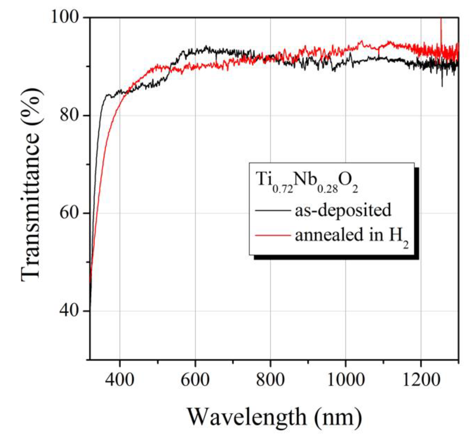
Annealing of the Ti0.72Nb0.28O2 films in H2 atmosphere also resulted in a substantial decrease of its electrical resistivity from 5.0 × 10² to 1.2 × 10⁻³ Ω cm. In spite of high conductivity, the annealed Ti0.72Nb0.28O2 film was highly transparent in the measured 400–1300 nm spectral region (Figure 3) with more than 93% transmittance within the 800–1000 nm range. Transmittance of the annealed and as-deposited Ti0.72Nb0.28O2 films was significantly higher than that of Ti0.8Nb0.2O2 film [23]. High conductivity and transmittance values suggest the annealed Ti0.72Nb0.28O2 film is a suitable candidate for transparent electrical interconnection for perovskite/silicon tandem solar cells.
The current–voltage (I–V) characteristics of TiO0.72Nb0.28O2/p+-Si heterojunction device on the base of 10−3 Ω cm resistivity silicon substrate measured at room and liquid nitrogen temperatures are shown in Figure 4.
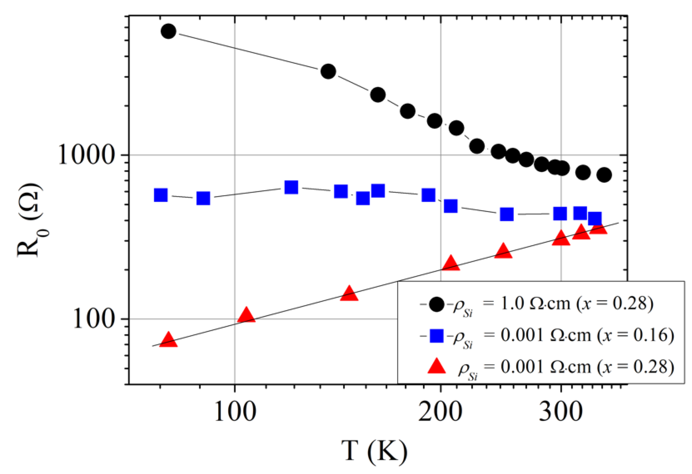
It is worth noting that the I–V characteristics were linear; it was another valuable property for the above-mentioned application. The resistance of such TiO0.72Nb0.28O2/p+-Si heterojunction device decreased as the sample was cooled down. Dependencies resistance-vs.-temperature for TiO1-xNbxO2/p-Si heterojunction devices with different content of x and formed on different Si substrates are depicted in Figure 5. It was seen that the resistance of TiO0.72Nb0.28O2/p+-Si heterojunction (substrate ρSi = 10−3 Ω cm) linearly increased with temperature. Such linear dependence was an inherent feature of the tunnel diode at small bias voltage.
In general, when the interband carrier tunneling takes place, the tunnel current across a p-n junction can be expressed as [26,27]:
It = AeU(EvEc)2/4kT,
where A is a constant, Ec and Ev represent the conduction and the valence band edges, respectively, and k is the Boltzmann constant. Expression (7) shows that the resistance of a tunnel p-n junction at low bias was a linear function of temperature. The Hall effect measurements indicate that electron density in TiO0.72Nb0.28O2 is 3.5 × 1021 cm−3 and therefore it can be regarded as a degenerate semiconductor [24,28,29]. Low resistivity p+-Si (ρ = 10−3 Ω cm) is also a degenerate semiconductor. The hole concentration determined from Hall effect measurements in p+-Si was 1.3 × 1020 cm−3. The energy band diagram of mutually heavily doped n+-TiO2/p+-Si heterojunction in equilibrium condition is shown in Figure 6. It is seen that electrons from TiO2 conduction band could tunnel through the gap to the empty sites of the p+-Si valence band under a small forward bias. Linear dependence of the resistance on temperature supports the assumption that the interband tunneling current took place in the investigated TiO0.72Nb0.28O2/p+-Si heterojunction. The specific contact resistivity of TiO0.72Nb0.28O2/p+-Si heterojunction was 23 mΩ·cm2 at room temperature which was better than 30 mΩ·cm2 achieved in [7].
As a rule, there are three main components of current in a tunnel diode: the tunnel current (It), the excess current (Ix) and the diffusion current (Id). The diffusion current is responsible for the current rise under high forward biases [26]. Therefore, Id should be negligible in comparison with the tunnel current at low bias. The excess current at low bias was mainly determined by the multistep tunneling recombination process via surface states at the TiO2/p+-Si interface [7,30]. Substantial density of localized surface states was determined by a large number of defects, Ns ~ 7.0 × 1013 cm−2, at the TiO2/p+-Si interface resulting from significant lattice mismatch between the heterojunction components [30]. These interfacial states can facilitate the band to band tunneling and act as generation-recombination centers at all bias voltages [7,31]. As the generation-recombination centers, the interface states had substantial influence on charge transport through TiO2/p+-Si tunnel heterojunction. At reverse bias, every recombination center becomes a source of carrier generation, and high electrical conductivity can be reached by thermally generated carriers [7]. Since the carrier generation–recombination strongly depends on the thermal energy, the multistep tunneling recombination process via surface states resulted in a substantial increase of the heterojunction resistance at lower lattice temperature. Such dependence of the resistance on temperature was observed in TiO0.72Nb0.28O2/p-Si heterojunction on low conductivity (ρSi = 1 Ω cm) p-type silicon substrate (see Figure 5, black circles). The band-to-band tunneling was impossible in this case, therefore the current through the TiO0.72Nb0.28 O2/p-Si heterojunction was mainly determined by the multistep tunneling recombination process via the surface states.
I–V characteristic of the TiO0.72Nb0.28O2/p-Si heterojunction was not linear (see Figure 7, solid black line) with forward current larger than the reverse one, as observed in other works [7,17,30]. Similar character demonstrated the I–V dependence of the TiO0.84Nb0.16O2/p+-Si device formed on the low resistivity substrate (Figure 7, blue long-dotted line). Electron density in the TiO0.84Nb0.16O2 film as determined from the Hall effect measurements was 1.9 × 1021 cm−3. Therefore, the TiO0.84Nb0.16O2 film could be also regarded as a degenerate semiconductor [24,28,29], and the band to band tunnel current could be present in the investigated TiO0.84Nb0.16O2/p+-Si heterojunction. Since electron density in the TiO0.84Nb0.16O2 was less than in the TiO0.72Nb0.28O2 layer, the tunnel current in TiO0.84Nb0.16O2/p+-Si heterojunction became of the same order of magnitude as the excess current due to multistep tunneling recombination process via the surface states at the TiO2/p+-Si interface. This consideration was supported by the dependence of the resistance of the TiO0.72Nb0.28O2/p-Si heterojunction device on temperature depicted in Figure 5 (blue squares). Very weak temperature dependence of the resistance was an inherent feature of the tunnel current consisting of two components, It and Ix [32].
Figure 7 also shows the I–V characteristic of the TiO0.84Nb0.16O2/p+-Si heterojunction device with as-deposited titanium oxide layer (red short-dotted line). As mentioned above, the as-deposited TiO0.84Nb0.16O2 film had an amorphous structure and therefore its conductivity was low. As a result, the I–V characteristic of the TiO0.84Nb0.16O2/p+-Si heterojunction device was nonohmic and asymmetric, as observed in other works [7,30].

4. Conclusions

Two different (x = 0.16 and x = 0.28) niobium composition containing heavily doped Ti1-xNbxO2 thin films were ALD-deposited on p-type Si substrates. Reductive post-deposition annealing was required to crystallize amorphous titanium dioxide into the anatase structure and to increase its electrical conductivity. The current-voltage characteristic of the TiO0.72Nb0.28O2/p+-Si heterojunction device is found to be ohmic, and the junction resistance linearly depends on temperature. In this case the current across the heterojunction is mainly stipulated by the interband charge carrier tunneling. When the highly conductive titanium dioxide is deposited on low conductivity (ρSi = 1 Ω cm) p-Si substrate, the current across the TiO0.72Nb0.28O2/p-Si heterojunction is mainly determined by the multistep tunneling recombination process via the surface states. The contact resistivity of the TiO0.72Nb0.28O2/p-Si heterojunction is higher than that of the TiO0.72Nb0.28O2/p+-Si heterojunction. The formed titanium dioxide films also demonstrate excellent transparency with absorption less than 10% in the visible region. Therefore, the TiO0.72Nb0.28O2/p+-Si heterojunction could be a suitable candidate as transparent interconnection in 2-T perovskite/silicon tandem solar cells.

Author Contributions

Conceptualization, S.A.; methodology, S.A., K.L. and A.S. (Algirdas Sužiedėlis); validation, A.S. (Algirdas Selskis), R.J., A.S. (Algirdas Sužiedėlis) and A.Š.; investigation, M.A., A.S. (Algirdas Selskis), L.S., S.S., A.L., R.J., A.Š. and E.Š.; resources, M.A., A.L., K.L., L.S. and A.Š.; writing—original draft preparation, J.G. and S.A.; writing—review and editing, J.G. and A.S. (Algirdas Sužiedėlis); visualization, A.S. (Algirdas Sužiedėlis); supervision, S.A.; project administration, S.A.; funding acquisition, S.A. All authors have read and agreed to the published version of the manuscript.

Funding

This work was funded by Research Council of Lithuania (Grant No 01.2.2-LMT-K-718-01-0050).

Acknowledgments

This work was supported by Research Council of Lithuania (Grant No 01.2.2-LMT-K-718-01-0050). The authors are grateful to Angelė Steikūnienė and Gytis Steikūnas for technical assistance in sample preparation.

Conflicts of Interest

The authors declare no conflict of interest.

References

  1. Mailoa, J.P.; Bailie, C.D.; Johlin, E.C.; Hoke, E.T.; Akey, A.J.; Nguyen, W.H.; McGehee, M.D.; Buonassisi, T. A 2-terminal perovskite/silicon multijunction solar cell enabled by a silicon tunnel junction. Appl. Phys. Lett. 2015, 106, 121105. [Google Scholar] [CrossRef] [Green Version]
  2. Asadpour, R.; Chavali, R.V.K.; Khan, M.R.; Alam, M.A. Bifacial Si heterojunction-perovskite organic-inorganic tandem to produce highly efficient (η*T ~33%) solar cell. Appl. Phys. Lett. 2015, 106, 243902. [Google Scholar] [CrossRef]
  3. Albrecht, S.; Saliba, M.; Baena, J.P.C.; Lang, F.; Kegelmann, L.; Mews, M.; Steier, L.; Abate, A.; Rappich, J.; Korte, L.; et al. Monolithic perovskite/silicon-heterojunction tandem solar cells processed at low temperature. Energy Environ. Sci. 2015, 9, 81–88. [Google Scholar] [CrossRef]
  4. Werner, J.; Weng, C.H.; Walter, A.; Fesquet, L.; Seif, J.P.; De Wolf, S.; Niesen, B.; Ballif, C. Efficient monolithic perovskite/silicon tandem solar cell with cell area > 1 cm2. Phys. Chem. Lett. 2016, 7, 161–166. [Google Scholar] [CrossRef] [PubMed]
  5. Werner, J.; Niesen, B.; Ballif, C. Perovskite/silicon tandem solar cells: Marriage of convenience or true love story?—An overview. Adv. Matter. Interf. 2017, 1700731. [Google Scholar] [CrossRef]
  6. Zheng, J.H.; Lau, C.F.J.; Mehrvarz, H.; Ma, F.J.; Jiang, Y.J.; Deng, X.F.; Soeriyadi, A.; Kim, J.; Zhang, M.; Hu, L.; et al. Large area efficient interface layer free monolithic perovskite/homo-junction-silicon tandem solar cell with over 20% efficiency. Energy Environ. Sci. 2018, 11, 2432–2443. [Google Scholar] [CrossRef] [Green Version]
  7. Shen, H.P.; Omelchenko, S.T.; Jacobs, D.A.; Yalamanchili, S.; Wan, Y.; Yan, D.; Phang, P.; Duong, T.; Wu, Y.; Yin, Y.; et al. In situ recombination junction between p-Si and TiO2 enables high-efficiency monolithic perovskite/Si tandem cells. Sci. Adv. 2018, 4, eaau9711. [Google Scholar] [CrossRef] [Green Version]
  8. Kojima, A.; Teshima, K.; Shirai, Y.; Miyasaka, T. Organometal halide perovskites as visible-light sensitizers for photovoltaic cells. J. Am. Chem. Soc. 2009, 131, 6050–6051. [Google Scholar] [CrossRef]
  9. Lee, M.M.; Teuscher, J.; Miyasaka, T.; Murakami, T.N.; Snaith, H.J. Efficient hybrid solar cells based on meso-superstructured organometal halide perovskites. Science 2012, 338, 643–647. [Google Scholar] [CrossRef] [Green Version]
  10. Burschka, J.; Pellet, N.; Moon, S.J.; Humphry-Baker, R.; Gao, P.; Nazeeruddin, M.K.; Grätzel, M. Sequential deposition as a route to high-performance perovskite-sensitized solar cells. Nature 2013, 499, 316–319. [Google Scholar] [CrossRef]
  11. Liu, M.; Johnston, M.B.; Snaith, H.J. Efficient planar heterojunction perovskite solar cells by vapour deposition. Nature 2013, 501, 395–398. [Google Scholar] [CrossRef] [PubMed]
  12. Wojciechowski, K.; Stranks, S.D.; Abate, A.; Sadoughi, G.; Sadhanala, A.; Kopidakis, N.; Rumbles, G.; Li, C.Z.; Friend, R.H.; Jen, A.K.Y.; et al. Heterojunction modification for highly efficient organic-inorganic perovskite solar cells. ACS NANO 2014, 8, 12701–12709. [Google Scholar] [CrossRef] [PubMed]
  13. Yang, B.; Dyck, O.; Poplawsky, J.; Keum, J.; Puretzky, A.; Das, S.; Ivanov, I.; Rouleau, C.; Duscher, G.; Geohegan, D.; et al. Perovskite Solar Cells with Near 100% Internal quantum efficiency based on large single crystalline grains and vertical bulk heterojunctions. J. Am. Chem. Soc. 2015, 137, 9210–9213. [Google Scholar] [CrossRef] [PubMed]
  14. Li, X.; Bi, D.; Yi, C.; Decoppet, J.D.; Luo, J.; Zakeeruddin, S.M.; Hagfeldt, A.; Grätzel, M. A vacuum flash-assisted solution process for high-efficiency large-area perovskite solar cells. Science 2016, 353, 58–62. [Google Scholar] [CrossRef]
  15. Yang, W.S.; Park, B.W.; Jung, E.H.; Jeon, N.J.; Kim, Y.C.; Lee, D.U.; Shin, S.S.; Seo, J.; Kim, E.K.; Noh, J.H.; et al. Iodide management in formamidinium-lead-halide-based perovskite layers for efficient solar cells. Science 2017, 356, 1376–1379. [Google Scholar] [CrossRef] [Green Version]
  16. Gao, X.-X.; Xue, D.-J.; Gao, D.; Han, Q.; Ge, Q.-Q.; Ma, J.-Y.; Ding, J.; Zhang, W.; Zhang, B.; Feng, Y.; et al. High-mobility hydrophobic conjugated polymer as effective interlayer for air-stable efficient perovskite solar cells. Sol. RRL 2018, 3, 1800232. [Google Scholar] [CrossRef] [Green Version]
  17. Ahiboz, D.; Nasser, H.; Aygün, E.; Bek, A.; Turan, R. Electrical response of electron selective atomic layer deposited TiO2-x heterocontacts on crystalline silicon substrates. Semicond. Sci. Technol. 2018, 33, 045013. [Google Scholar] [CrossRef]
  18. Anitha, V.C.; Banerjee, A.N.; Joo, S.W. Recent developments in TiO2 as n- and p-type transparent semiconductors: Synthesis, modification, properties, and energy-related applications. J. Mater. Sci. 2015, 50, 7495–7536. [Google Scholar] [CrossRef]
  19. Dueñas, S.; Castán, H.; García, H.; San Andrés, E.; Toledano-Luque, M.; Mártil, I.; González-Díaz, G.; Kukli, K.; Uustare, T.; Aarik, J. A comparative study of the electrical properties of TiO2 films grown by high-pressure reactive sputtering and atomic layer deposition. Semicond. Sci. Technol. 2005, 20, 1011–1051. [Google Scholar] [CrossRef]
  20. Nabatame, T.; Ohi, A.; Chikyo, T.; Kimura, M.; Yamada, H.; Ohishi, T. Electrical properties of anatase TiO2 films by atomic layer deposition and low annealing temperature. J. Vac. Sci. Technol. B 2014, 32, 03D121. [Google Scholar] [CrossRef]
  21. Nowotny, M.K.; Bak, T.; Nowotny, J. Electrical properties and defect chemistry of TiO2 single crystal. I. Electrical conductivity. J. Phys. Chem B 2006, 110, 16270–16282. [Google Scholar] [CrossRef] [PubMed]
  22. Bak, T.; Nowotny, J.; Nowotny, M.K. Defect disorder of titanium dioxide. J. Phys. Chem. B 2006, 110, 21560–21567. [Google Scholar] [CrossRef] [PubMed]
  23. Furubayashi, Y.; Hitosugi, T.; Yamamoto, Y.; Inaba, K.; Kinoda, G.; Hirose, Y.; Shimada, T.; Hasegawa, T. A transparent metal: Nb–doped anatase TiO2. Appl. Phys. Lett. 2005, 86, 252101. [Google Scholar] [CrossRef]
  24. Niemelä, J.-P.; Hirose, Y.; Shigematsu, K.; Sano, M.; Hasegawa, T.; Karppinen, M. Suppressed grain-boundary scattering in atomic layer deposited Nb:TiO2 thin films. Appl. Phys. Lett. 2015, 107, 192102. [Google Scholar] [CrossRef]
  25. Potlog, T.; Dimitriu, P.; Dobromir, M.; Manole, A.; Luca, D. Nb-doped TiO2 thin films for photovoltaic applications. Mater. Des. 2015, 85, 558–563. [Google Scholar] [CrossRef]
  26. Seeger, K. Semiconductor Physics, 2nd ed.; Springer: Berlin/Heidelberg, Germany, 1982; p. 462. [Google Scholar]
  27. Ašmontas, S.; Gradauskas, J.; Petkun, V.; Seliuta, D.; Sužiedėlis, A.; Urbelis, A. Hot electron effect in degenerate semiconductor tunnel junction. Acta Phys. Pol. 2005, 107, 198–202. [Google Scholar] [CrossRef]
  28. Nogawa, H.; Chikamatsu, A.; Hirose, Y.; Nakao, S.; Kumigashira, H.; Oshima, M.; Hasegawa, T. Carrier compensation mechanism in heavily Nb-doped anatase Ti1-xNbxO2+δ epitaxial thin films. J. Phys. D Appl. Phys. 2011, 44, 365–404. [Google Scholar] [CrossRef]
  29. Niemelä, J.-P.; Marin, G.; Karppinen, M. Titanium dioxide thin films by atomic layer deposition: A review. Semicond. Sci. Technol. 2017, 32, 093005. [Google Scholar] [CrossRef]
  30. Mostovyi, A.I.; Brus, V.V.; Maryanchuk, P.D. Charge transport mechanisms in anisotype n-TiO2/p-Si heterostructures. Semiconductors 2013, 47, 799–803. [Google Scholar] [CrossRef]
  31. Zide, J.M.O.; Kleiman-Shwarsctein, A.; Standwitz, N.C.; Zimmerman, J.D.; Steenblock-Smith, T.; Gossard, A.C.; Forman, A.; Ivanovskaya, A.; Stucky, G.D. Increased efficiency in multijunction solar cells through the incorporation of semimetallic ErAs nanoparticles into tunnel junction. Appl. Phys. Lett. 2006, 88, 162103. [Google Scholar] [CrossRef] [Green Version]
  32. Björk, M.T.; Schmid, H.; Bessire, C.D.; Moselund, K.E.; Ghoneim, H.; Karg, S.; Lörtscher, E.; Riel, H. Si-InAs heterojunction Esaki tunnel diodes with high current densities. Appl. Phys. Lett. 2010, 97, 163501. [Google Scholar] [CrossRef]
Figure 1. (a) Schematic cross-section of the TiO2/p-Si heterojunction device. (b) Microphotograph top view of TiO2/p-Si (∅ 100 μm) and Au/TiO2 (∅ 600 μm) contacts (b).
Materials 13 02857 g001
Figure 2. XRD patterns of the Ti0.72Nb0.28O2 film before (dark line) and after annealing in H2 atmosphere (red line).
Materials 13 02857 g002
Figure 3. Transmittance of the annealed and as-deposited Ti0.72Nb0.28O2 film on a glass substrate.
Materials 13 02857 g003
Figure 4. Current–voltage characteristics of TiO0.72Nb0.28O2/p+-Si heterojunction device formed on the 10−3 Ω cm resistivity silicon substrate at room (red solid line) and liquid nitrogen (blue dashed) temperatures.
Materials 13 02857 g004
Figure 5. Dependence of the low bias resistance of TiO1−xNbx O2/p+-Si heterojunction devices on temperature. The devices differ in the amount of Nb in the TiO2 layer (x = 0.28 and 0.16) and in conductivity of the silicon substrate (ρSi = 10−3 Ω cm and 1 Ω cm).
Materials 13 02857 g005
Figure 6. Energy band diagram of n+–TiO2/p+-Si tunnel heterojunction in an equilibrium condition.
Materials 13 02857 g006
Figure 7. Current–voltage characteristics of TiO1−xNbx O2 /p-Si heterojunction device measured at room temperature. Solid curve is for x = 0.28 and low conductivity p-Si.
Materials 13 02857 g007