Article

Stability Analysis of Plate—Screw Fixation for Femoral Midshaft Fractures

by
Izzawati Basirom
1,
Ruslizam Daud
1,
Muhammad Farzik Ijaz
2,*,
Mohd Afendi Rojan
1 and
Khairul Salleh Basaruddin
1
1
Fracture and Damage Mechanics (FDM), Faculty of Mechanical Engineering Technology, University Malaysia Perlis, Arau 02600, Perlis, Malaysia
2
Mechanical Engineering Department, College of Engineering, King Saud University, P.O. Box 800, Riyadh 11421, Saudi Arabia
*
Author to whom correspondence should be addressed.
Materials 2023, 16(17), 5958; https://doi.org/10.3390/ma16175958
Submission received: 15 June 2023 / Revised: 25 July 2023 / Accepted: 4 August 2023 / Published: 30 August 2023
(This article belongs to the Special Issue Material, Design and Biological Studies of Bones & Implants)

Abstract

:
An understanding of the biomechanical characteristics and configuration of flexible and locked plating in order to provide balance stability and flexibility of implant fixation will help to construct and promote fast bone healing. The relationship between applied loading and implantation configuration for best bone healing is still under debate. This study aims to investigate the relationship between implant strength, working length, and interfragmentary strain (εIFM) on implant stability for femoral midshaft transverse fractures. The transverse fracture was fixed with a fragment locking compression plate (LCP) system. Finite element analysis was performed and subsequently characterised based on compression loading (600 N up to 900 N) and screw designs (conventional and locking) with different penetration depths (unicortical and bicortical). Strain theory was used to evaluate the stability of the model. The correlation of screw configuration with screw type shows a unicortical depth for both types (p < 0.01) for 700 N and 800 N loads and (p < 0.05) for configurations 134 and 124. Interfragmentary strain affected only the 600 N load (p < 0.01) for the bicortical conventional type (group BC), and the screw configurations that were influenced were 1234 and 123 (p < 0.05). The low steepness of the slope indicates the least εIFM for the corresponding biomechanical characteristic in good-quality stability. A strain value of ≤2% promotes callus formation and is classified as absolute stability, which is the minimum required value for the induction of callus and the maximum value that allows bony bridging. The outcomes have provided the correlation of screw configuration in femoral midshaft transverse fracture implantation which is important to promote essential primary stability.

1. Introduction

Orthopaedic bridge-plating fixation has been studied extensively. Bone-healing studies have highlighted the complications involved in the delayed union, non-unions, fracture after device removal, and infection, mostly in the diaphysis and meta-diaphyseal fractures [1,2]. Subsequently, the complication risks were minimised by utilising biomechanical behaviour knowledge of the implant fixation and tissue vascularity. In recent years, the development of improved implant fixation has provided reliable stability for orthopaedic surgeon applications and has been of considerable interest [3,4,5]. Current biomechanical improvement efforts have been focused on to enhance the bone–intramedullary nail system stability [6]; for example, the exploration of using additive manufacturing and the finite element (FE) method for the design, diagnosis, and planning of a locked intramedullary nail used in the diaphyseal femoral fractures mainly to simulate the osseointegration bone implant [7]. Based on statistical data, implant failure that occurred on the plate (42.4%) was more common than unlocked nails (33.3%) and subsequently locked nails (24.2%); occurrences of this failure were reported that were the result of fatigue failure (42.4%), bending (27.27%), loosening (18.8%), and infection (5.5%) [8]. In addition, researchers also revealed that implant failure was caused by the stress-shielding effect and overloading condition in the implant [9,10]. Subsequently, implant loosening may influence the bone remodelling process, whereas bone loss around screws leads to fixation failure. Thus, it is essential to consider the implant stability and the critical stress of implant fixation.
Among all the implant fixations, the locking compression plate was improved to achieve better fracture union compared with conventional plating which was stiffer in allowing bone healing. Moreover, flexibilities of the locking characteristic were necessary to enable interfragmentary motion (IFM) to directly stimulate a new bone bridge at the fracture site [11]. The rigid engagement of the locking screw to the plate provides fixed-angle stabilisation compared with the plate–bone compression of the conventional screw [12]. A few studies suggested that fixed-angle stabilisation with a unicortical locking screw provides distinct advantages over the conventional screw. However, the advantages remain inadequate for both screw types.
The function of a bridge plating with a screw construct was developed in advance based on a stability requirement of a particular fracture. These implants act as load-sharing or load-bearing devices, depending on the fracture reduction and fragment interference [13]. Implant instability and mechanical failure are related to poor stress-sharing loads and implant loosening [14,15]. Despite the high flexural strength, implant fixation can distribute the induced stresses. The effect of the screw types and configuration on the stress sharing, however, has been mentioned less. In addition, implant stability is influenced by such factors as the type of loading, the implant connection, the type of material, and the bone–implant interfaces [16,17,18,19]. It is necessary to analyse the bone properties, structure, and load resistance in biomechanics analysis [20]. A similar factor to be considered is the implant contact pressure between the femur and tibia [20]. To date, the finite element (FE) approach that employs structural analysis is the most successful approach for simulating the bone–implant interface.
Different designs of bone geometry have shown different results for stress and subsequent deformations. Two-dimensional FE modelling representing the bone–implant structure is based on the assumption that the load is axially symmetrical [21]. Most of the 2D-model studies give satisfactory insight into the behaviour of the bone–implant interface. However, the stress analysis of bone predicted by the 2D model is also known to be less accurate compared with the 3D model [22,23]. This is because the assumptions of the 2D model only consider a cross section view to represent the information in bone tissue around the implant. However, a 3D-modelling technique must be adopted first to determine the external loading in order to show the overall deformation and stress distribution.
In one study, the stability spectrum was scaled as a quantitative condition of implant stability [24]. Micromotion is essential to improve the osseointegration processes in broken bones and indirectly provides biological or secondary stability [25,26,27,28,29]. However, excessive movements can reduce the stability of the implant and the healing of the bones. Therefore, knowledge of both primary and secondary stability and the spectrum is emphasised in this study.
Some studies suggest that optimal screw configuration can minimise healing time and also surgical costs [30]. Researchers established that the number of screws increased the rigidity of the implant structure. Instead, one fundamental concept found throughout the literature is that more screws do not mean more stability [31]. It can be concluded that, for a diaphysis fracture, three or four screws are sufficient [32]. This study aims to evaluate the mechanical behaviour of a fragment locking compression plate (LCP) system as a function of screw type, screw configuration, and penetration depth using a finite element model (FEM). The literature on the subject has contrasting recommendations on optimal screw numbers and configurations, mostly based on empirical evidence.

2. Materials and Methods

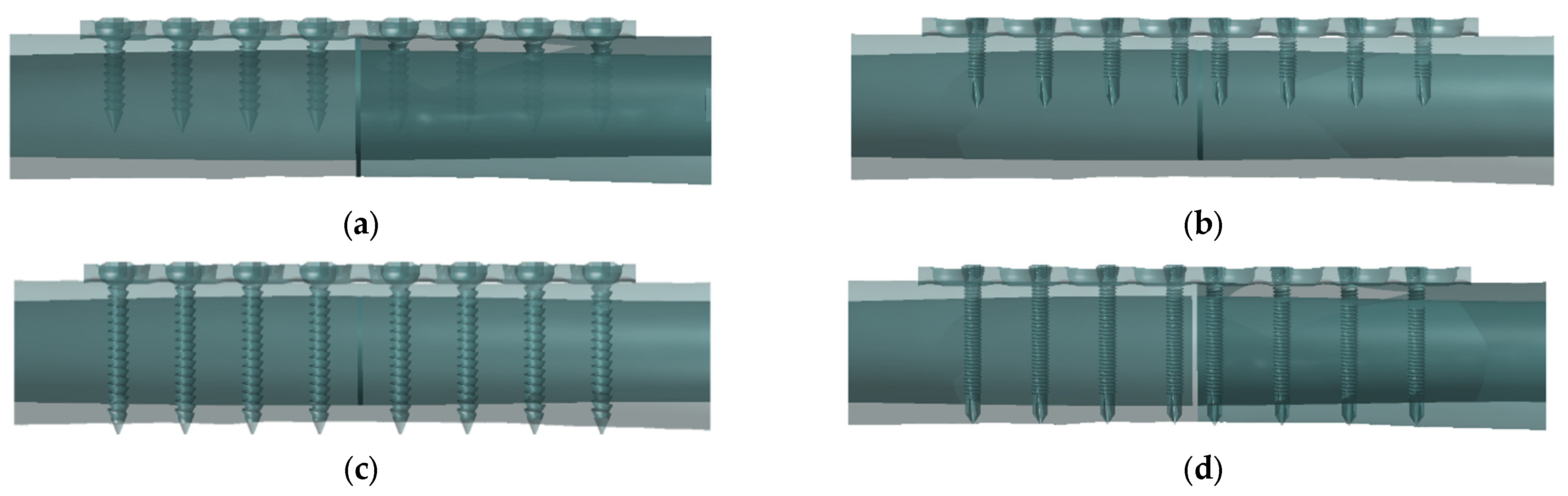
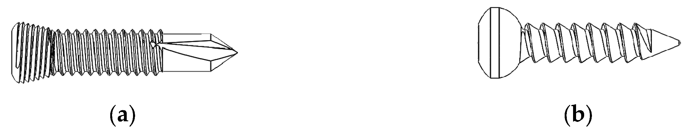
2.1. Implant–Bone Fixation System

In this study, the three stages of internal implant fixation are involved which are implant–bone fixation, implant–bone loading condition, and implant–bone screw penetration. Implant fixation was studied based on the mechanical response: (i) when implant placement is performed on the femur, (ii) when the compression loading is applied on the femur bone, and (iii) there is a different type of screw and penetration depth. The four surgical fixation groups—unicortical conventional screw (UC), unicortical locking screw (UL), conventional bicortical screw (BC), and bicortical locking screw (BL)—are shown in Figure 1.

2.2. 3D Model of Implant–Bone Configuration

Three parts of the fixation system were constructed: screws, a compression plate, and an intact femur bone. The intact femur model was applied before mimicking the actual bone from CT scan through the computer-aided design (CAD) model library [33]. The models were a modified cortex thickness averaging approximately 5 mm in thickness, and the midsection of the femur bone was the focus. The screw and a fragment compression plate were designed using SolidWorks version 2020, Mechanical Design Lab, Faculty of Mechanical Engineering Technology (Dassault, MA, USA). All implants were designed according to the Synthes product [34]. Reverse engineering has been defined for obtaining the geometry of implant parts. An adaptive reconstruction method used by enclosing the original point creates a point set by recursively subdividing each point into a sub-point. In addition, the resulting mesh is obtained by subdividing the coarser mesh and adapting the topology at the location where points have been removed. Final mapping locally constraining the mesh toward the concentrated point will often influence accuracy and results. In this study, conventional screw lengths of 18 mm (product number: 204.818) and 36 mm (product number: 204.821) were used. Subsequently, locking screws of 18 mm (product number: 212.112) and 36 mm (product number: 212.105) and a compression plate with eight holes were used (product number: 223.581). Both types of screw models were designed as shown in Figure 2. ANSYS Design Modular v18 was used to assemble the bone and implant using Boolean operation. In this study, the static structural module was used to simulate the bone implant fixation. Figure 3a shows that eight holes in the LCP were numbered from Position 1 to 8 (P1–P8), and the four configurations are shown in Figure 3b–e.
In accordance with the Arbeitsgemeinschaft für Osteosynthesefragen/Association of the Study of Internal Fixation (AO/ASIF) procedure [35], the plate is located on the lateral side of the femur. This study involved the locking conventional screw construction with LCP. Four groups were categorized—group UC, group UL, group BC, and group BL—and then followed by the number of configurations. These configurations were selected as the control group based on current configurations in clinical practice [31]. A 1 mm fracture gap was used between bone fragments as suggested by the previous study that the gap should not exceed 2 mm for osseointegration [36].

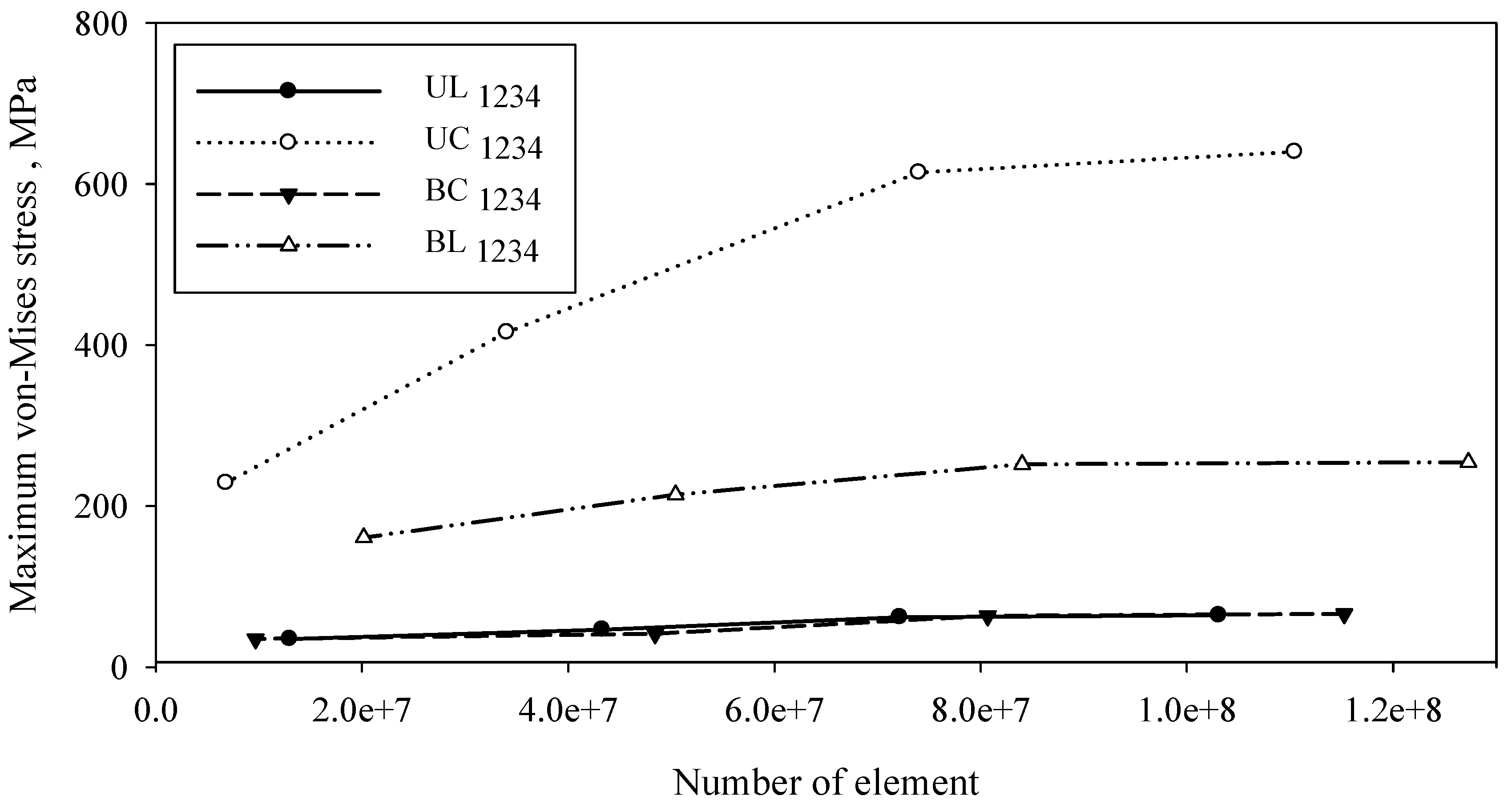
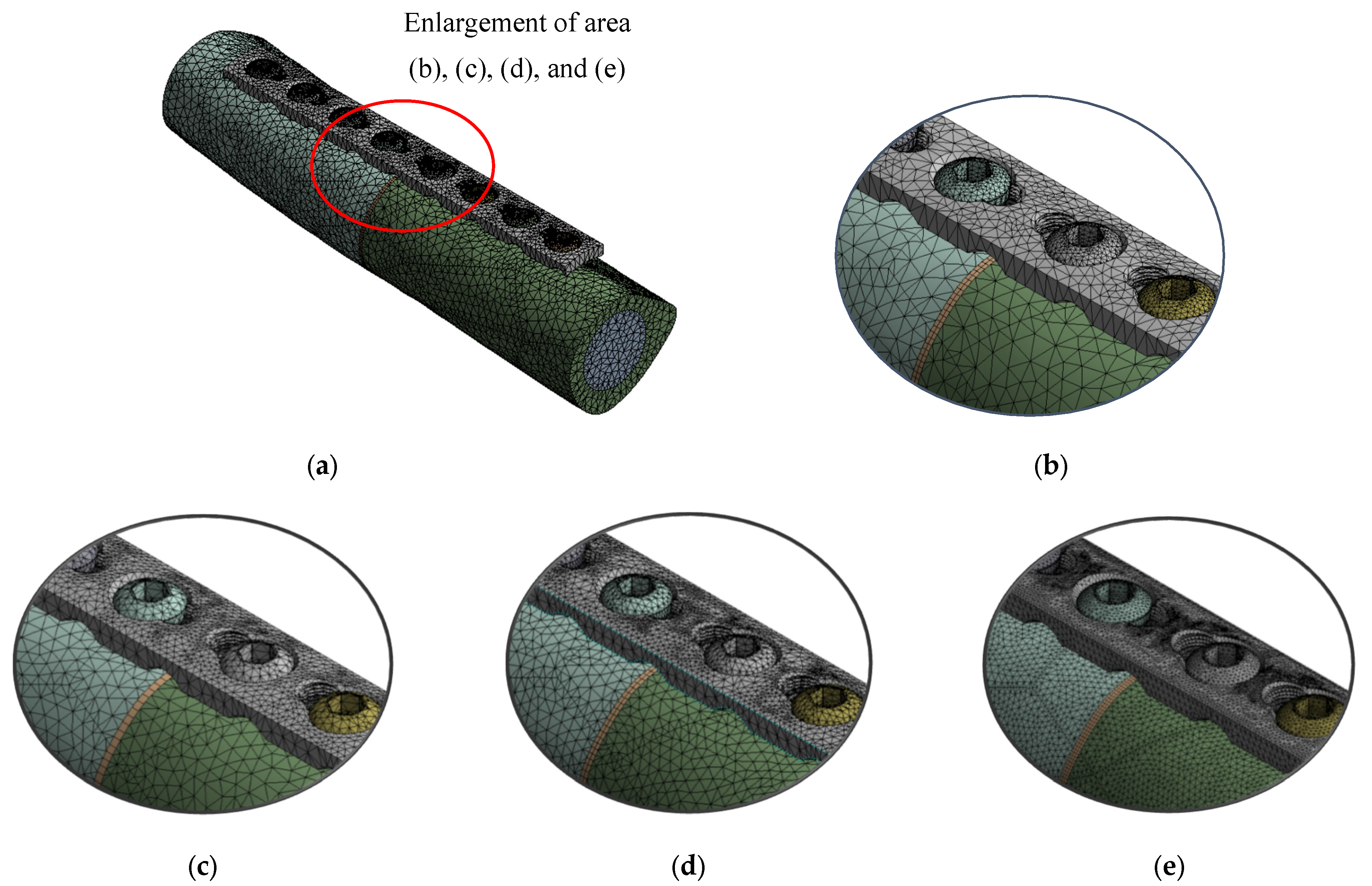
2.3. Mesh and Validation

Tetrahedron element mesh was used for all models. Table 1 shows the statistics of mesh with nodes and elements of the level of element sizes for different types of implant configuration. The model validation is based on internal FE validation through convergence analysis. Figure 4 shows a convergence test performed for 16 types of configuration according to groups UC, UL, BC, and BU. Figure 5 shows the meshed model with an enlargement area for four variations of mesh: default, coarse, medium, and fine size. An element size of 0.4 mm with a transition ratio of 0.272 and a growth rate of 1.2 was used.

2.4. Fixation Interface Condition

The interaction approach between contact pair is classified as bone–screw, implant–screw, and implant–bone. The fixation system model employed the interaction as a simple contact that was frictionless between the implant and bone surface. The friction coefficients between 0.1 and 0.3 were compared [24], and the result shows that friction has a less significant effect on bone–implant stress results [37]. The implant is assembled as a model of tightening to define it in such a way that it describes complete bone healing surrounding the implant. Despite the minimal effect of friction on the result, it can be clarified as a rigid or contact pair between bone–implant interfaces. The different interaction properties are summarised in Table 2.

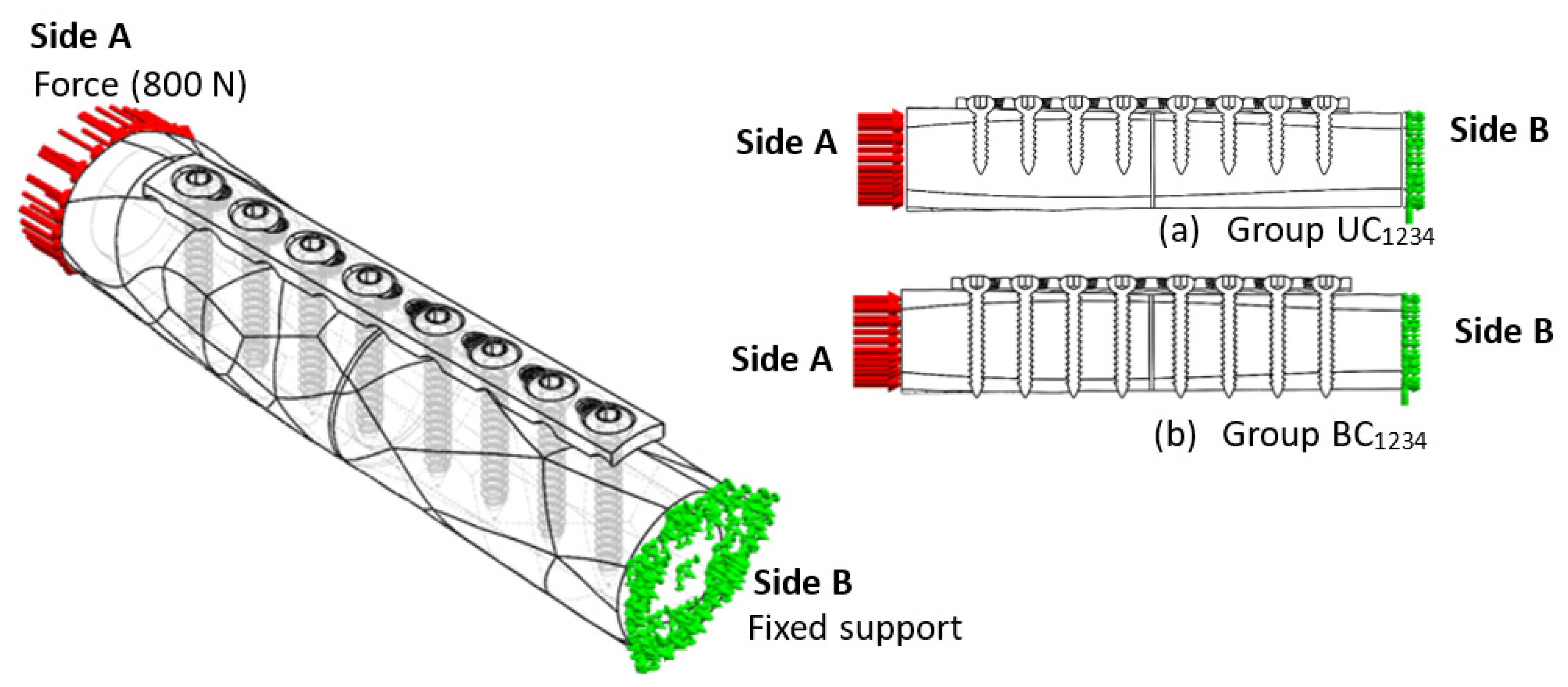
2.5. FE Simulation of Compression Load

A constant load of 800 N was applied once the preliminary steps were achieved. It has been demonstrated to correspond to the load on the femur during regular activities such as standing up. The rationale relation between dynamic and static loading demonstrated that the average dynamic force applied on the femur is representative of the constant load based on human weight (i.e., 600 N, 700 N, 800 N, 900 N). Sides A and B represent the compression loading and constraint, respectively, and the schematic of these four loading conditions is illustrated in Figure 6a,b. This assumption approximates the actual condition of the anterior and posterior regions of the femur shaft. A simplified model was used to provide information about the screw–plate configuration affecting the mechanical behaviour of the bone–implant system [38]. This simplified model allows the parametric study of bone–implants involving stress distribution and stress shielding that influence the construct’s stability. The assembly force used in this study was applied as a compression rather than an impact, as is the case during surgery. A dynamic impact load can be replaced by compression as it results in a similar strength [39].

2.6. Identification of Material Properties

Table 3 shows the mechanical properties of the bone–implant model. The femur bone consists of two sections: cortical and trabecular bone. The orthotropic elastic behaviour was used for the cortical bone, whereas the other parts are assumed to behave as the isotropic elastic behaviour. Orthotropic elasticity can represent actual bone properties because it can show the bone structure composition [40,41]. Additionally, simplified biological information was used, such as a 1% formed callus representative of 0.2 GPa of Young’s modulus in the 1 mm fracture gap. The compression plate and screw parts and their material properties were measured [42].

2.7. Stability Characterisation

The primary stability of implant fixation is related to the implant’s micromotion, which is defined as a displacement that refers to a small movement of bone fragments at the fracture site. It can be characterised by the implant’s stress analysis, working length analysis, interfragmentary strain measurement, and stability classification.

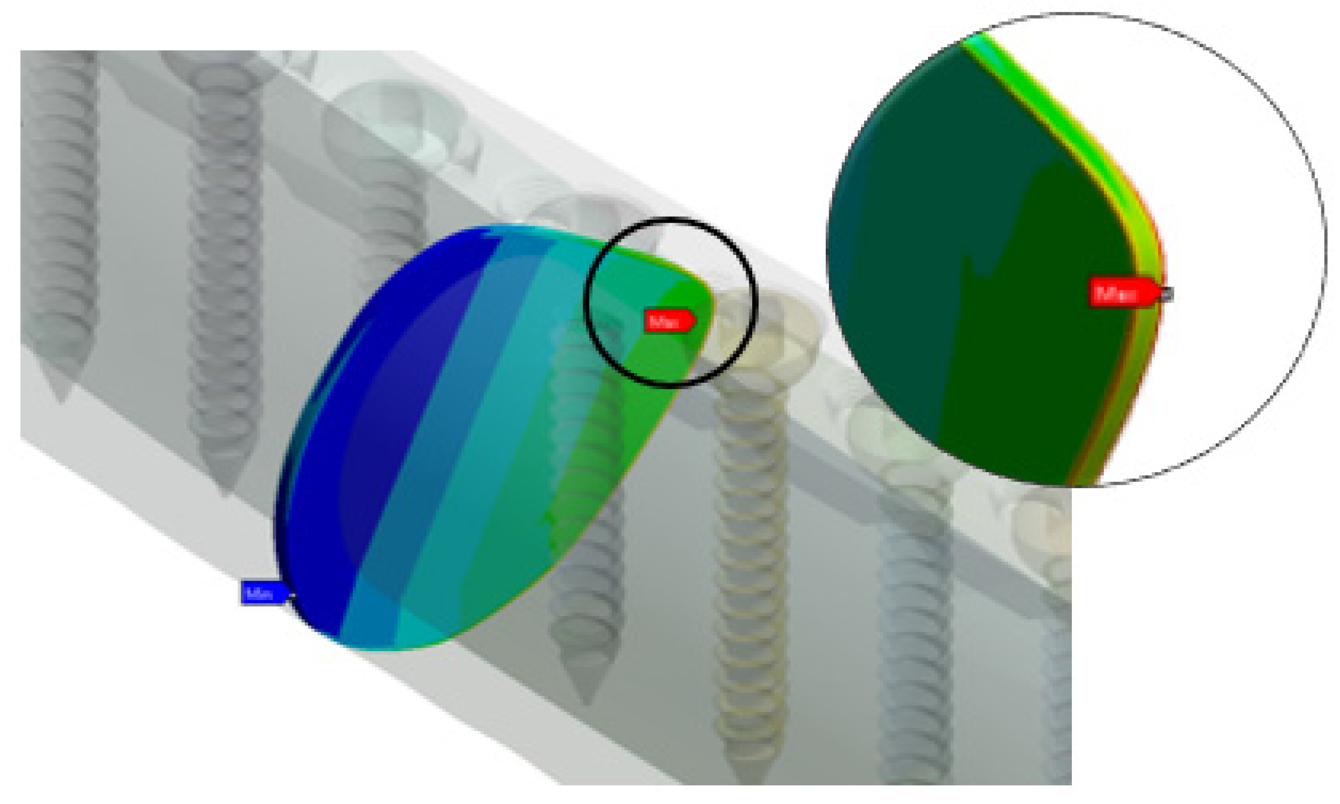
2.7.1. Implant Stress Analysis

The implant fixation with two screw types was modelled; subsequently, the implant strength was appropriately computed. The four screw types were simulated by four configurations at various penetration depths. The overall results were determined using the maximum von Mises stress of the implant. The mechanical properties of stainless steel were used to estimate the stress required to initiate the crack and to cause implant loosening and failure. The changing stress value affects Young’s modulus bone neighbour and causes jumps in stress values in the bone.

2.7.2. Working Length Measurement

Further investigation was carried out in simulating a relationship between working length and maximum von Mises stress by taking the average of the implant equivalent of stress for each working length. Working length refers to the distance between the two innermost screws. By omitting one screw hole on either side of the fracture, the construct became flexible in both compression and torsion. The relationship between working length and implant stress was determined, in order to differentiate the rigidity and flexibility based on screw configurations.

2.7.3. Interfragmentary Strain Measurement

Interfragmentary strain at the fracture gap filled by the callus was calculated using the comparison of the initial length of the fracture gap and the gap size under stress based on the end point of both bone fragment connectors with the callus. Perren’s strain theory was used for observing the implant stability. Strain values up to 2% promoted the formation of lamella tissue and at this stage can be classified as absolute stability. In addition, up to 10% are tolerated by the woven bone formation, and for between 10% and 30%, induction of resorption prevails. The interfragmentary of each construct was determined using the following equation:
ε I F = L / L
where ε I F is interfragmentary strain, ∆L is changing between initial length and length under stress, and L is the initial length = 1 mm.

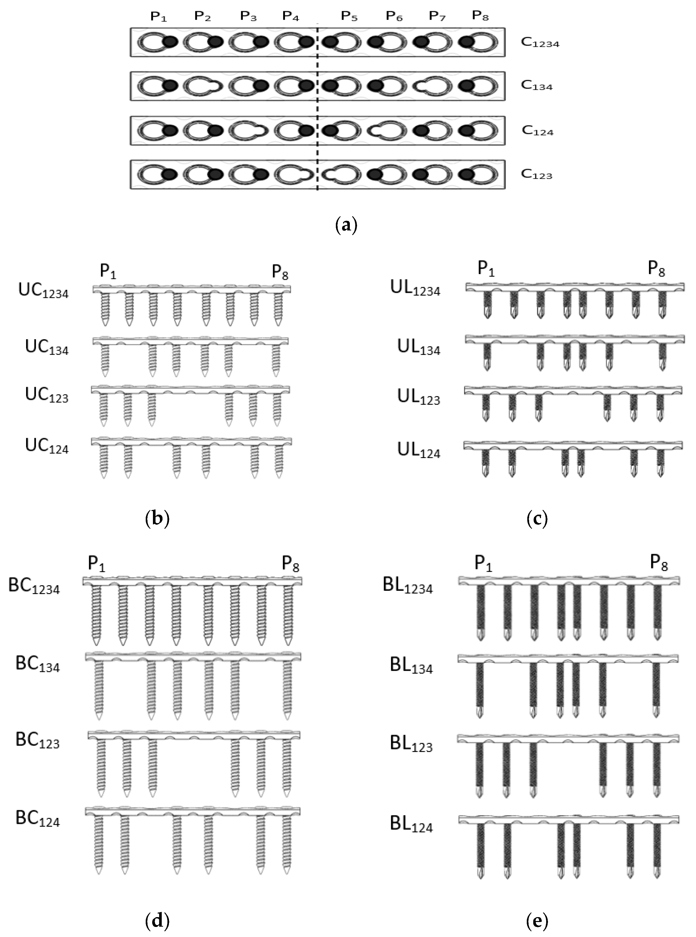
2.7.4. Stability Classification

Implant stability was evaluated based on screw type and its configuration. Absolute stability was achieved by compression load at the fracture site, where small gaps of 1 mm are bridged by bone growth. The stabilisation at the fracture site determined the further course of bone healing [43]. Stability is divided into three scales: absolute stability (2%), relative stability (range 2% to 10%), and instability (greater than 10%); interfragmentary strain can be utilised to account for bone healing rate. The stability of interfragmentary strain was determined using the following conditions:
ε I F 2 % Absolute   stability
2 % ε I F 10 % Relative   stability
ε I F 10 % Instability

3. Results and Discussion

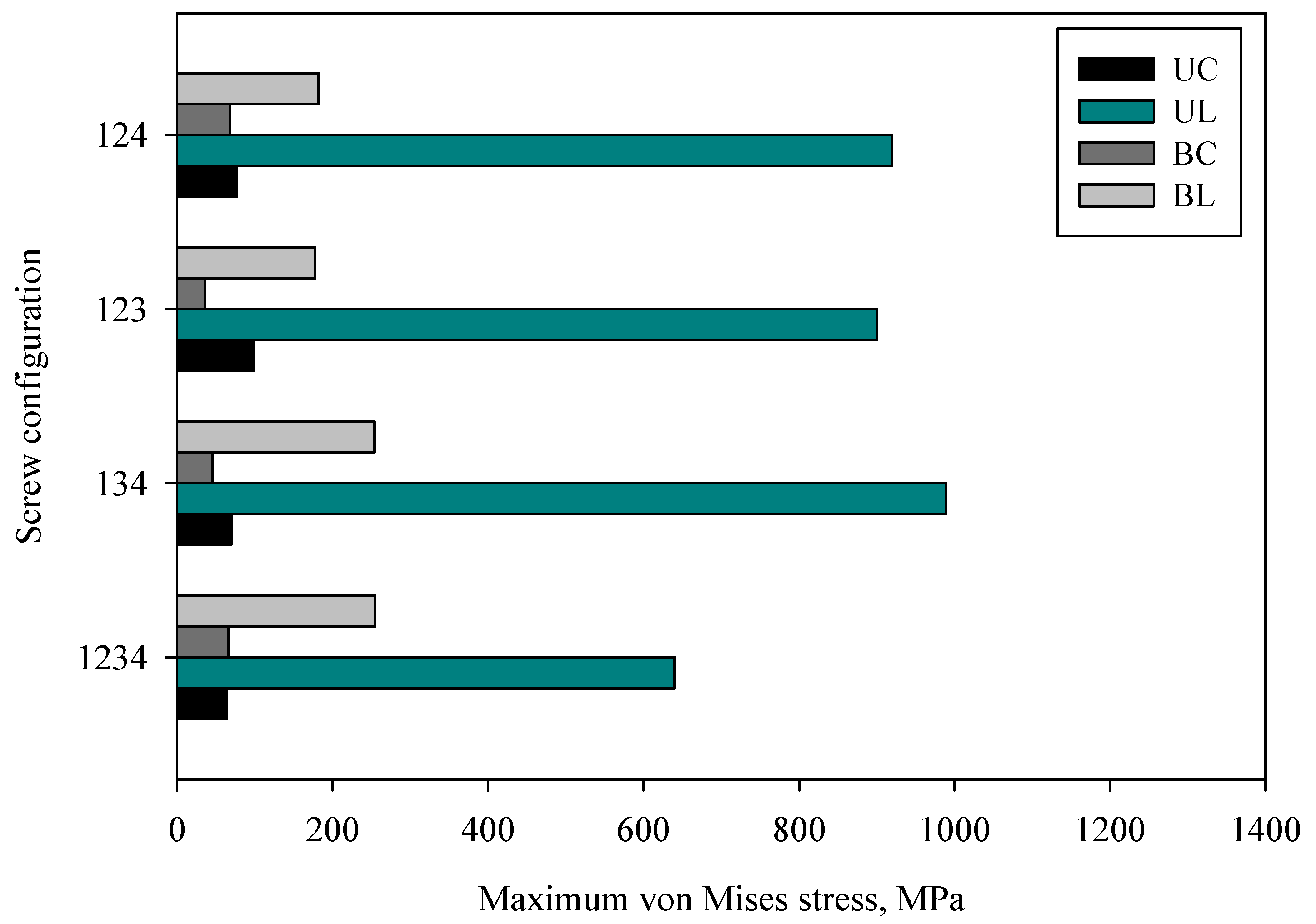
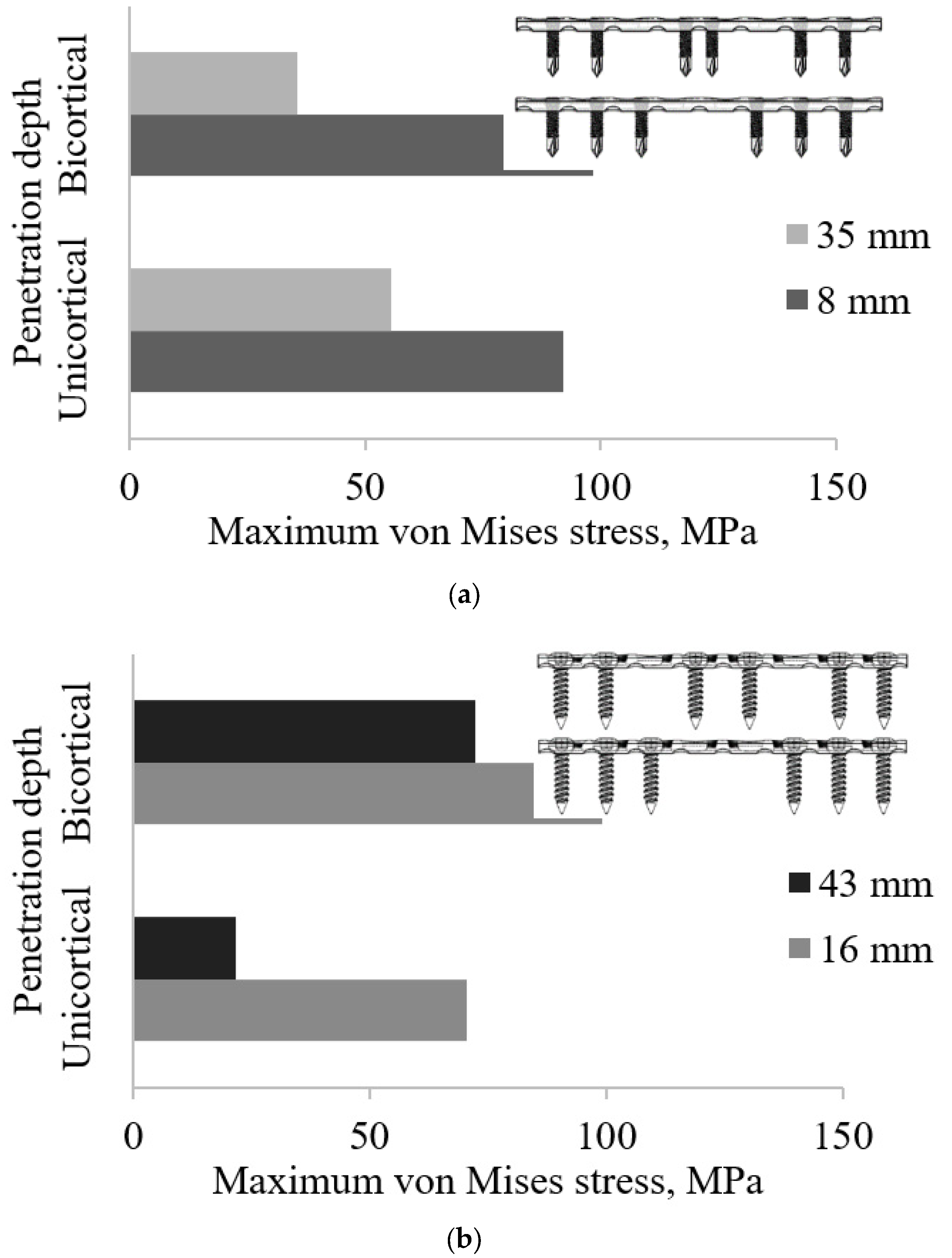
3.1. Effect of Screw Types and Penetration Depth Configuration

Figure 7 shows the effects of screw configuration on the implant stress for different screw types. In general, the different screw types and configurations yield a different stress distribution threshold. The results obtained for the Groups UL and BL were superior to those of Groups UC and BC. The implant strengths of Groups UC and BC were relatively lower and uniform. On the contrary, the strength of Groups UL and BL was rough and irregular. As the screw configurations changed, the implant strengths of both penetration depths were reduced, indicating optimal stability for bone–implant fixation.
When the configurations of screw types were compared, group UC showed the highest strength of UC123 with a maximum of 99.24 MPa, followed by the UC124, which had a maximum stress of 76.78 MPa. The most stable construct was observed for UC1234, with a minimum stress of 64.48 MPa; moreover, this configuration had considerably larger stability than those seen for UC134, UC123, and UC124. The high stress of the implant leads to mechanical failure. However, the low stresses may cause stress shielding, which could lead to bone resorption and implant loosening [44].
Considering the locking screw construction with various screw configurations, all exhibit high values concerning the penetration depth. The maximum strength (989.26 MPa) was determined in group UL134. Groups UL1234, UL123, and UL124 yielding average strengths of 639.77 MPa, 900.65 MPa, and 919.59 MPa, respectively. The implant strength of Groups UC and UL was relatively higher for Configuration 1234. Subsequently, UC1234 shows the least stress value compared with UL1234. This is due to the exceeding resistive strength of cortical bone, whereas bone resorption and screw loosening occurred. This loosening occurred because of the high interfragmentary strain, which can increase micro movement at the fracture gap and subsequently change the implant stability level [45].
Compared with group UL, critical stress was found at UL134 with a maximum of 989.26 MPa, followed by UL124, which had maximum stress of 919.59 MPa. The most stable group UL construct was found to be UL1234, which had a maximum stress value of 639.77 MPa. In hindsight, group UC and group UL for C1234 were the most stable, while the UC1234 construct yielded lower stress than UL1234. This is because of an axial load exceeding the frictional force and producing a high-stress transfer to the bones and neighbouring interfaces.
Group UL123 showed the least strength (177.75 MPa), while the configurations of UL1234, UL134, and UL124 had strengths of 254.41 MPa, 254.23 MPa, and 182 MPa, respectively. In addition, for group BL, BL123 experienced the maximum stress of 99.24 MPa, which is similar to the stress experienced by the BL1234 (64.48 MPa), BL134 (70.12 MPa), and BL123 (76.78 MPa) configurations. Groups BC and BL exhibit that C123 was the most stable. This attests to an earlier suggestion that the number of screws does not necessarily equate to an increase in stability. The fewer-screw predictably will increase the load sharing for individual screws; however, the stability also can be controlled by changing the working length. A similar observation was also reported by Stoffel [46].
Groups BC and BL were very stable compared with groups UC and UL because both groups penetrate through the two stiff layers of the bone cortex. Shortening of the screw length results in a substantial increase in the compressive stress [14], whereas the screw diameter influenced the strength or holding power [35]. The load sharing to the bone was higher for the conventional screw compared with the locking screw. The stress distributes from the plate to the screw head through locking threads. This is caused by the high wear rate for the bone, as the bone cortex creates counteracting forces under axial loading, mainly at the implant interface. These changing stress values affect the consistency of Young’s modulus bone neighbouring and cause jumps in stress values in the bone. Thus, major jumps in stress occur in bone. The reason behind these jumps is the nature of bone remodelling and changing values of Young’s modulus bone during the healing process. The highlighted finding was that the high stress of implants provides a less stable bone–implant system. This can be observed from group UC123 (35.78 MPa) being the most stable group. The strength and deformation of the implant depend on the bending moment of plating the bridge. This bending condition varies based on the screw position and the distance between the two innermost screws.
The desired yield stress is in the range of 400 MPa. The stress variation has to initiate and propagate a crack with the screw and implant being estimated whereas the stress raisers will lead to the implant failure. The standing load itself (applied on the distal extremity) needed to be representative of the minimum strength of the human activity performed by the patient between surgery and implant failure. In addition, implant stress becomes relevant to determine the amount of transfer stress from the implant to the neighbouring bone which may affect the implant stability in terms of micro movement. The presence of the two innermost screws acts as a lever or fulcrum. These changes in distance are known as the ‘working length’. Further factors considered in the internal fixation of bone plate fixation include the implant working length.

3.2. Effect of Implant Type (Unicortical) on the Stress Distribution of Screw and LCP Plate

Figure 8 shows the maximum von Mises stress on the implant screws and plate for locking the unicortical screw; it had a uniform stress distribution. Configuration UL1234 had high stress concentrated at position P5, which focused on the threaded head, while the plate concentrated on the hole threaded for screws and plate. Configuration UL134 had high stress concentrated at position P8, which focused on the end of the threaded head, while the plate concentrated on the hole threaded for the screws and plate.
Configuration UL123 showed the critical stress concentrated on the P1 screw position, and it was located on the screw head and neck. Similar observations were found at position P1, where critical stress was found in the threaded hole. The failure stress of UL1234 was higher than that for UC1234, the screw failure was shown based on the type of screw. Stress riser initiates the locking mechanism of the UL screw. Similarly, Configuration UL124 showed the critical stress concentrated on the P8 screw position, and it was located on the screw head and neck. Matching to the plate, position P8 indicated critical areas for the fracture of the thread conjunctions and screw holes. The same observations were found in UL134 and UL124. Overall observations found that the critical failure stress occurred on the screw head with the thread and the screw threaded hole. This was because critical stress transfer occurred as the locking head screw engaged and locked into the threaded plate hole.

3.3. Effect of Implant Type (Bicortical) on the Stress Distribution of Screw and LCP Plate

Figure 9 shows the maximum von Mises stress on the implant screws and plate for group BC. Configuration BC1234 showed the critical stress concentrated on the screw at position P8, and it was located on the proximal thread. Similar findings were observed for BC134 and BC123. The results are in good agreement with those reported by Lofaj et al. [14]. Unlike the screws, the plates showed P4 to have critical pressure at the bottom of the plates near the threaded hole. Configuration BC134 showed the critical stress concentrated on the position P5 screw position and was located on the screw head and neck. Similar to the plate, position P6 showed a critical area located at the screw hole with thread conjunction and screw holes near the fracture site. Similar plate stress concentrations were also observed for UC1234, UC134, and UC123.
Position P3 of BC123 showed that critical stress occurred on the screw and neck. For the plates, the critical stress concentrated on position P6 in the conjunctions of screw holes with thread and screw holes near the fracture site. A similar observation was made for BC124, where greater stress was obtained on position P1 for both implants. This is caused by a load transfer from the proximal fragment to the distal fragment through the plate. Most of the critical stress occurred on the distal fragment and concentrated on the screws innermost from the fracture site.

3.4. Effect of Working Length as a Function of Screw Configurations on Plate Stress

Figure 10a shows the plate strength of the locking screw at different levels of working length. The configurations of the unicortical and bicortical screws for C1234, C134, and C124 generated an 8 mm working length compared with C123 of both types of penetration, which provided a 16 mm working length. The working length and screw configuration were more important than the number of screws [42], whereas the rigidity and flexibility of the implant were key to implant stabilisation.
The average of maximum von Mises plate strengths of Groups UL and BL showed that the bicortical screw had more significant changes in plate stress. Increasing the working length from 8 mm to 35 mm reduced the plate stress by 98.33 MPa to 35.78 MPa, respectively. Under axial loading, the reduction for 35 mm was approximately 60% of 8 mm. For the unicortical screw, 8 mm of working length (91.99 MPa) showed a higher stress value compared with 35 mm (55.42 MPa), as shown in Figure 10b. The working length can make the plate overly flexible and can result in plate breakage [47,48].
Figure 10b shows the screw strength of Groups UC and BC at both penetration depths. It seems that the average equivalent stress of 16 mm for the unicortical screw was higher than that of the bicortical screw; however, it was the contrary for 43 mm. As the innermost screws increased from 16 mm to 43 mm, the plate stresses of bicortical (99.24 MPa to 72.3 MPa) and unicortical (70.46 MPa to 21.51 MPa) types were reduced. The pull-out strength variance between unicortical and bicortical screws was between 26% and 44% [49]. Unlike unicortical screws, which experience high stress, it is inversely proportional to the working length. It also provides higher stress on the 16 mm compared with the 43 mm screws, on top of having different stress distributions. In general, both types of screw show that the unicortical was most affected by the plate stress compared with the bicortical screws for the working length range.
The wider working length decreases the equivalent stress in the implant. The working length enables early mobilisation and bone bridges in the fracture gap to occur [50], whereas the small working length minimises plate strain [50]. This relates to the rigidity and flexibility of the implant; however, an unexpected finding was that implant stress was reduced by reducing the working gap of the unicortical locking. The wider working length was found to decrease the plate stress. As expected, reduced plate rigidity increases the εIFM, and thus the bone strain also increased.

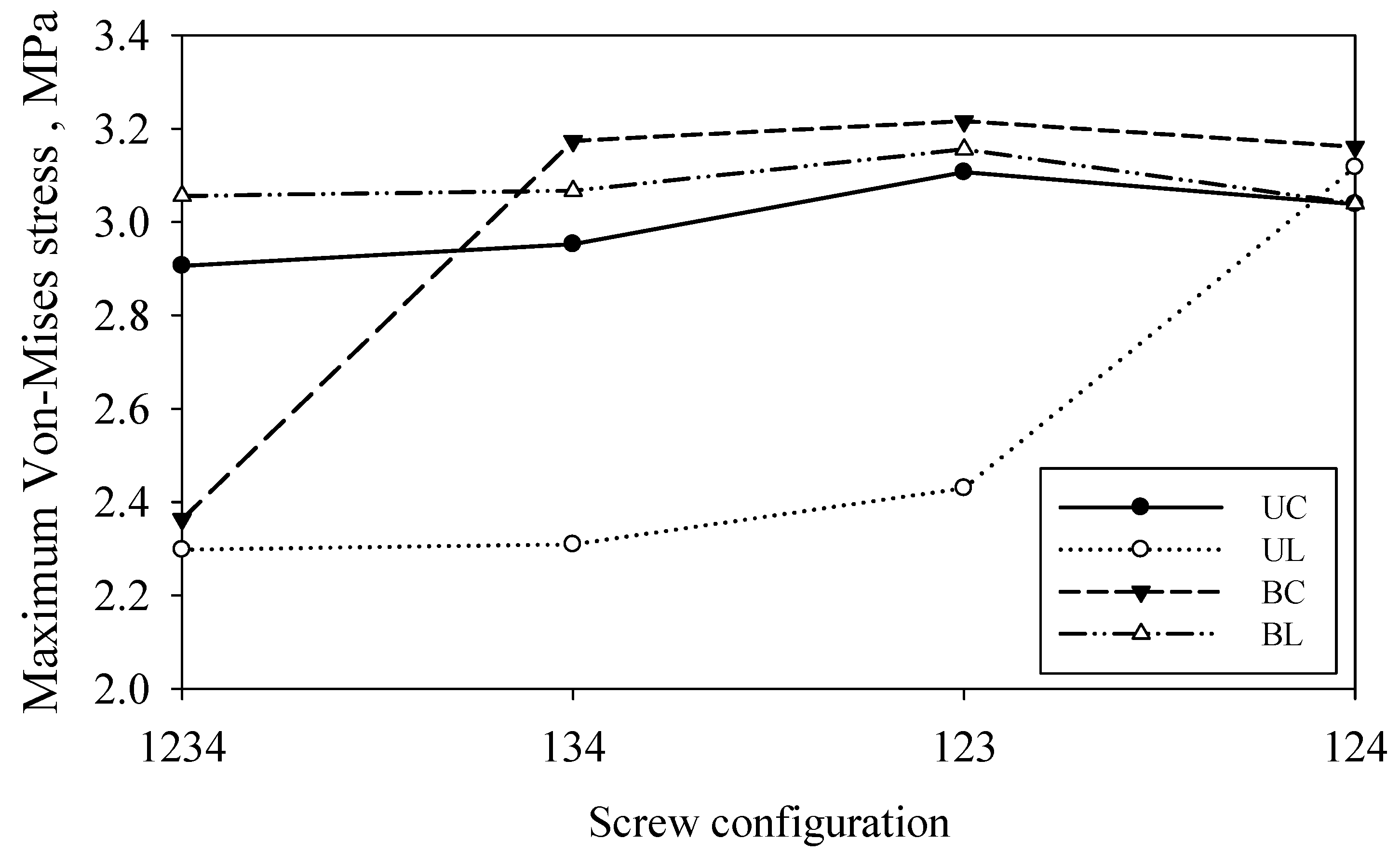
3.5. Effect of Screw Configuration on the Callus Stress

Figure 11 shows the maximum stress of the callus for both screw types and the penetration depth. Overall, the data show callus stress in the range of approximately 2.2 MPa to 3.2 MPa. The results obtained show good agreement with those reported by Froud et al. They found that the callus stress ranges between 2 MPa and 3 MPa [51]. This supports the hypothesis that bone remodelling after fracture healing is mainly pressure driven with the differentiation of compression structure. It can be correlated between the mechanical strain of callus and bone remodelling and is supported by Wolff’s law [52]. Figure 12 demonstrates that the maximum stress occurred on the fracture site or callus bone at different group screws. Group BL yielded the highest stress for all configuration ranges while group UL had the lowest stress in callus.

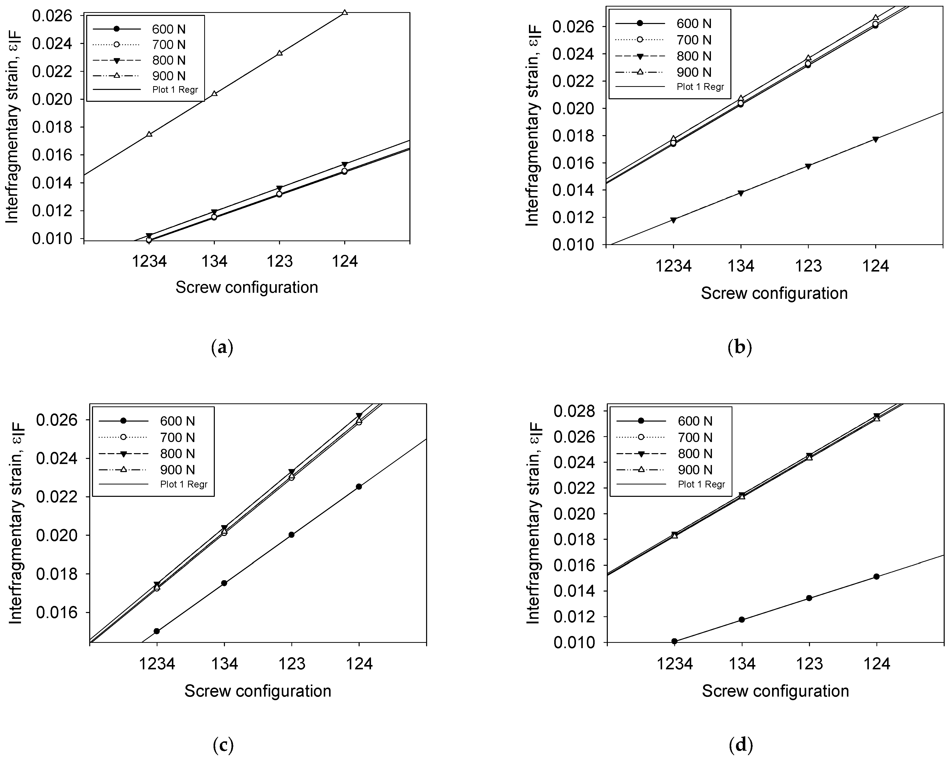
3.6. Interfragmentary Strain as a Function of Screw Configuration

Table 4 shows the relationship between screw configurations and the interfragmentary strain at a fracture gap with 800 N of compression load. The obtained interfragmentary strain was more significant than 0.01 for all configurations. The correlation between screw configurations and the interfragmentary strain was obtained to examine the implant stability. In a unicortical group, screw configuration had a small and marginal effect on the interfragmentary strain.
In bicortical groups, the amount of strain gradually increased as the pattern of screw configuration changed from C1234 to C124. Absolute stability was achieved in all configurations of bicortical screws compared with the unicortical group. In addition, relative stability was obtained for both types of unicortical screw groups for all configurations except C1234, where it showed a value of less than 2% strain. This result was not reported as a strategy for optimising fixation stability for these types of screws, for screw position relative to the fractured bone.
Compression applied to the fracture produced preloaded continuous contact and, thus, minimised interfragmentary strain. This enabled the osteons to cross the fracture at the compressed surfaces. The osteons may also cross small gaps stabilised by neighbouring compressed areas of contact. However, the minimal strain did not induce the formation of callus. The displacement of the implant micromotion affected the net resorption that begins to bond the gap, while its tension depended on the tolerable limit of soft tissue formed. This can lead to a reduction in the stress-shielding effect. The closer of the innermost screws to the fracture site resulted in a more significant impact on the interfragmentary strain εIFM rather than the number of screws itself. The findings are supported by Lee et al. [49]. They revealed that the appropriate selection of the types of screw and configuration is essential in achieving bone healing, and fewer screws consequently yield less damage to the soft and hard tissues, thus reducing the surgery costs.

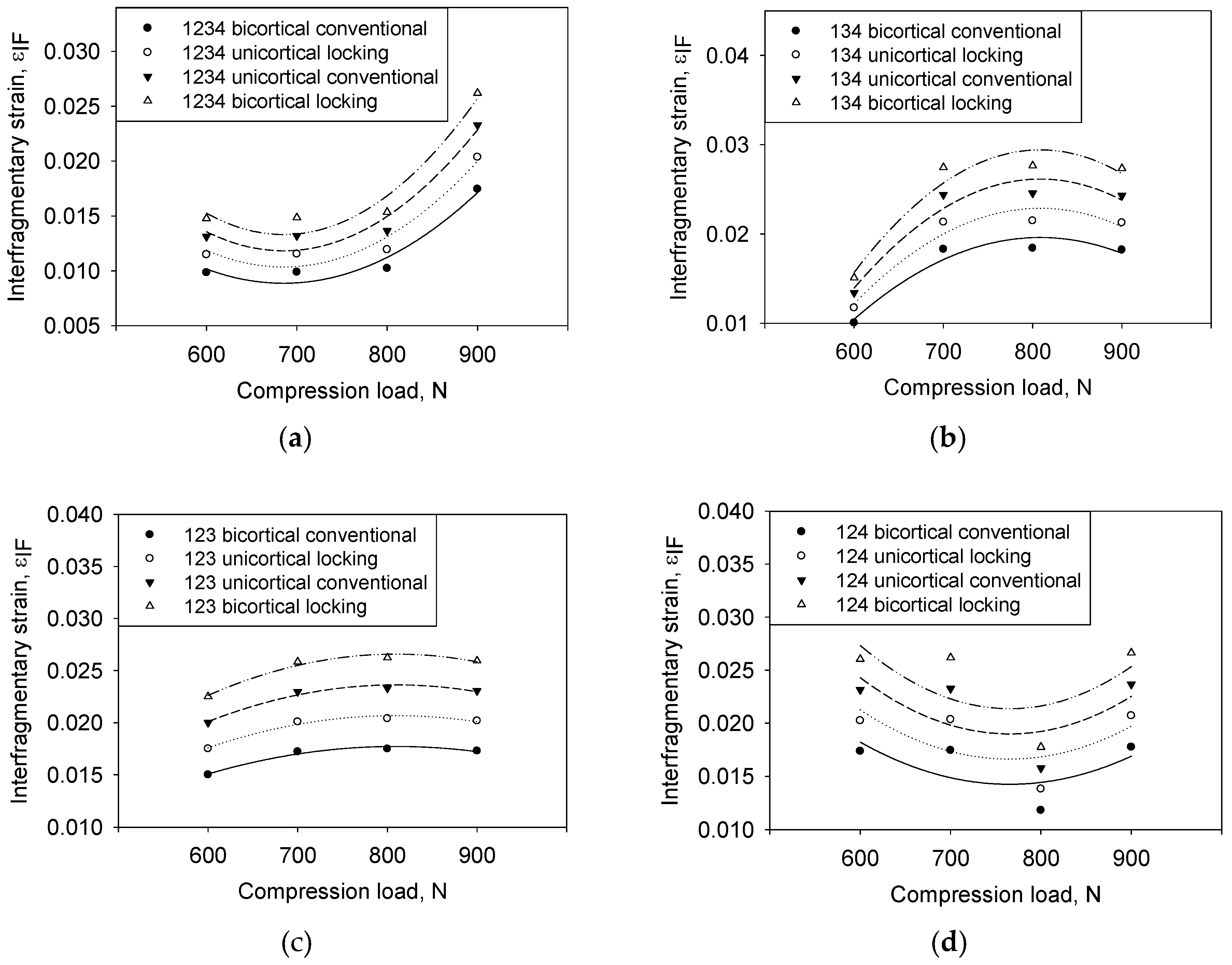
3.7. Interfragmentary Strain as a Function of Compression Loading

Figure 13 shows the relationship between configurations and interfragmentary strain for all compression loads. In general, the interfragmentary strain increases with increasing loads for all types of screws and configurations. The non-linear regression line was compared to determine the most stable implant of screw type and screw configurations. Figure 13a-d show the responses of εIFM properly fit the curvatures, whereas all data adequately cover the entire range of loads. The effect of increasing loads on the callus strain also gradually increases. However, the effect of changing the screw configuration on load increment cannot be easily summarized. Thus, the correlation of the distribution data was simplified by using regression analysis, as shown in Table 5.
The effects of each type of screw and their configuration were estimated using the residual sum of squares by using 95% of the confidence interval for the parameters. Table 5 shows group BC was the least value for all types of configurations. The small value of the residual sum of squares indicates a more stable implant. The variance shows the effect of εIFM highly depends on the screw type and screw configuration with an increment of loads.
As shown in Table 6, the model specifies the relationship between εIFM and loads, which were compared by the p-value obtained from the normality test and shows a significant level fitting to assess the null hypothesis. The screw configuration of C1234, C134, and C123 concluded the model is statistically significant based on non-linear regression as the p-value obtained (p ≤ 0.05) compared to the configuration 124 (p ≥ 0.05). The value of εIFM is statistically significantly different between the screw configurations and compression loads. In these results, the normality of distribution also performed by Shapiro–Wilk indicates a p-value > 0.1. Thus, the null hypothesis is accepted for all screw configurations and loads for all input response influence on εIFM.
The constant variance test results show the εIFM passed the test of the assumption that the variance of loads in the screw configuration takes a small variance. The p-value computed for the C1234 and C124 shows an uneven spreading of residual across the fitted line, indicating a non-constant variance as it is far away from a zero value, 0.7048 and 0.9432, respectively.

3.8. Interfragmentary Strain as a Function of Compression Loading

Figure 14 shows a linear relationship between the load and the interfragmentary strain for all different screw configurations. Based on Perren’s theory, the compression load ranges between 700 N and 800 N; this is most critical for changing the tissue phenotype [48]. The increasing pattern of εIFM follows a linear function concerning the compression loading. The steeper slope indicates lesser stability of bone–implant, such as BL compared with group UL, of which the latter is more stable. Researchers have stated that the distance of the fracture gap and loads can quantify the implant stability [50]. However, varying the screw type and configuration also can be the most significant factor contributing to stability. The most stable screw type was group BC, and the most unstable screw type of group UC could be identified as the slope of the regression line, as shown in Figure 14. This result implies that the change in load exertion has a more significant impact on the interfragmentary strain [51] in comparison with changing the screw type.
From the regression analysis, the relationship between interfragmentary strain and compressive load can be linearised as Equation (5):
ε I F = a + b L
where a and b are constants, while L is compression load. The values of a and b are shown in Equation (2). L is the independent variable, and ε I F is the dependent variable.
Equation (2) and Table 7 shows that good linear relationships between variables were obtained, as shown in Figure 14a–d. Unexpected, distributed data found in group BC and UC show a high influence on εIFM compared with other groups. The probability of the regression line was used to elucidate the behaviour of variable parameters. This is because the comparison slope of the line can show stability behaviour [52]. At this stage, the stimulation of tissue differentiation during fracture healing after the granulation tissue is initiated [53]. Group BC was less steep (slope = 1.64 × 10⁻³) compared with other configurations, which indicates the least interfragmentary strain and the most-stable construct. It also explains that replacing locked with nonlocked diaphyseal screws does not significantly decrease construct stiffness and does not enhance interfragmentary motion [54].

3.9. Correlation between the Controllable Parameters on Interfragmentary Strain as Stability Determination

Table 8 presents the correlation between the screw configuration and screw type. Based on the Pearson correlation analysis, Groups UC and UL have significant values (p < 0.01) for 700 N and 800 N of load. The screw configuration for 134 and 124 had a substantial effect on the result of the interfragmentary strain (p < 0.05) for both configurations. Moreover, group BC indicated that interfragmentary strain had an effect only for 600 N (p < 0.01), and the screw configurations influenced were 1234 and 123 with a significant value (p < 0.05). This relationship is related to the location of bone formation and resorption which explained the high and low local mechanical strain [55].
Table 9 shows a correlation between compression load and screw type for the interfragmentary strain. Based on the statistical data, the correlation between 600 N and group BC has a significant effect on the interfragmentary strain. However, an unexpected response was obtained with 700 N and 800 N; this shows the significant impact on the interfragmentary strain (p < 0.05), indicating a favourable correlation with screw configuration mainly for group UC (p < 0.01). Moreover, the screw configuration under the load is not significant (p > 0.05) for 900 N.

4. Conclusions

In summary, a bone–implant fixation system consisting of different types of screws with different penetration depths (groups UC, UL, BC, and BL) was developed and investigated. The regression slope of compression was found to be the lowest for group BC (slope = 1.64 × 10⁻³) and highest for group UC, suggesting appropriate sampling distributions for the hypothesis for the strain result. Under compression loading, screw type shows a significant effect (p < 0.01) on the interfragmentary strain. The correlation of screw configuration with screw type shows a noteworthy impact on group UC and UL, having a significant value (p < 0.01) for 700 N and 800 N of the load and p < 0.05 for the configurations of C134 and C124. The interfragmentary strain had an effect only for 600 N (p < 0.01) for group BC and the screw configurations that were influenced were C1234 and C123 (p < 0.05). Moreover, the slope response of ε against the load was steeper, owing to the less stable bone–implant model. The amount of strain optimally ranged between the minimum required for the induction of callus and the maximum that allows bony bridging. Strain values ≤ 2% promote the callus formation and were classified as absolute stability. The correlation between εIFM and the type of screw showed scattered data of low quality for all types of screws mainly for bicortical conventional or group BC. Thus, the obtained determination coefficient was higher to achieve a reliable prediction of stability. If it is desirable to use group BC and C134 or BC134, it is recommended. This is important to address the biomechanical characteristics of flexible and locked plating to provide a balance between the stability and flexibility of implant fixation constructs and directly promote secondary bone healing. There is an excellent linear correlation between compression loading and screw type. For future research, a similar study can be conducted for different dynamic loading which can medically explain the more actual condition of a fracture. New exploration on the effect of screw configuration at microscale levels that concentrates on the area of the bone–implant interface is highly recommended.

Author Contributions

Conceptualization, I.B., R.D., M.F.I., M.A.R. and K.S.B.; methodology, I.B., R.D., M.F.I., M.A.R. and K.S.B.; software, I.B., R.D., M.A.R. and K.S.B.; validation, I.B., R.D., M.F.I., M.A.R. and K.S.B.; formal analysis, I.B., R.D., M.F.I., M.A.R. and K.S.B.; investigation, I.B., R.D., M.F.I., M.A.R. and K.S.B.; resources, I.B., R.D., M.F.I., M.A.R. and K.S.B.; data curation, I.B., R.D., M.F.I., M.A.R. and K.S.B.; writing—original draft preparation, I.B., R.D., M.F.I., M.A.R. and K.S.B.; writing—review and editing, I.B., R.D., M.F.I., M.A.R. and K.S.B.; visualization, I.B., R.D., M.F.I., M.A.R. and K.S.B.; supervision, I.B., R.D., M.F.I., M.A.R. and K.S.B.; project administration, M.F.I.; funding acquisition, M.F.I. All authors have read and agreed to the published version of the manuscript.

Funding

The authors extend their appreciation to the Deputyship for Research and Innovation, “Ministry of Education” in Saudi Arabia for funding this research through project no. (IFKSUOR3–584–1).

Institutional Review Board Statement

Not applicable.

Informed Consent Statement

Not applicable.

Data Availability Statement

The data obtained in this study are available from the corresponding author upon request.

Conflicts of Interest

The authors declare no conflict of interest.

References

  1. Alemdar, C.; Azboy, I.; Atiç, R.; Özkul, E.; Gem, M.; Kapukaya, A. Management of infectious fractures with ‘Non-Contact Plate’ (NCP) method. Acta Orthop. Belg. 2015, 81, 523–529. [Google Scholar]
  2. Ito, K.; Perren, S.M. Biology of fracture healing. J. Trauma Orthop. 2017, 5, 48–52. [Google Scholar]
  3. Hammarstedt, J.E.; Redshaw, J.T., Jr.; Schimoler, P.J.; Westrik, E.R.; Andreini, D.; Kharlamov, A.; Miller, M.C. Biomechanical analysis of stability of joint depression calcaneal fractures:Fixation with locking compression plate alone compared with addition of supplemental oblique screw. J. Clin. Orthop. Trauma 2022, 33, 101998. [Google Scholar] [CrossRef]
  4. Kuan, F.; Hsu, K.; Hong, C.; Chen, Y.; Chiang, C.; Chang, H.; Su, W. Biomechanical comparisons of hook plate and screw fixations in split-type greater tuberosity fractures of the humerus. J. Shoulder Elb. Surg. 2021, 31, 1308–1315. [Google Scholar] [CrossRef]
  5. Jang, Y.; Kim, D. Biomechanical study of Proximal humeral fracture fixation: Locking plate with medial support screw vs. locking plate with intramedullary fibular graft. Clin. Biomech. 2021, 90, 105510. [Google Scholar] [CrossRef]
  6. Rosa, N.; Marta, M.; Vaz, M.; Tavares, S.M.O.; Simoes, R.; Magalhaes, F.D.; Marques, A.T. Intramedullary nailing biomechanics: Evolution and challenges. Proc. Inst. Mech. Eng. Part H J. Eng. Med. 2019, 233, 295–308. [Google Scholar] [CrossRef]
  7. Fernandes, M.G.; Alves, J.L.; Fonseca, E.M.M. Diaphyseal femoral fracture: 3D biomodel and intramedullary nail created by additive manufacturing. Int. J. Mater. Eng. Innov. 2016, 7, 130–142. [Google Scholar] [CrossRef]
  8. Kumar, S.; Kumar, D.; Gill, S.P.S.; Singh, P.; Raj, M.; Gupta, A. Evaluation of Implant Failure in Long Bones Fractures—A Retrospective Study. Indian J. Orthop. Surg. 2016, 2, 64–68. [Google Scholar] [CrossRef]
  9. Eberle, S.; Gerber, C.; von Oldenburg, G.; Hogel, F.; Augat, P. A biomechanical evaluation of orthopaedic implants for hip fractures by finite element analysis and in-vitro tests. J. Eng. Med. 2010, 224, 1141–1152. [Google Scholar] [CrossRef]
  10. Gefen, A. Computational simulations of stress shielding and bone resorption around existing and computer-designed orthopaedic screws. Med. Biol. Eng. Comput. 2002, 40, 311–322. [Google Scholar] [CrossRef]
  11. Stephan, M. Internal Fixation of Long Bone Fractures: The Scientific Basis of Biological Internal Fixation. J. Bone Jt. Surg. 2007, 84, 1–24. [Google Scholar]
  12. Fitzpatrick, D.C.; Doornink, J.; Madey, S.M.; Bottlang, M. Relative stability of conventional and locked plating fixation in a model of the osteoporotic femoral diaphysis. Clin. Biomech. 2009, 24, 203–209. [Google Scholar] [CrossRef]
  13. Niemeyer, P.; Südkamp, N.P. Principles and clinical application of the locking compression plate (LCP). Acta Chir. Orthop. Traumatol. Cech. 2006, 73, 221–228. [Google Scholar] [CrossRef] [PubMed]
  14. Lofaj, F.; Kucera, J.; Nemeth, D.; Kvetkova, L. Finite element analysis of stress distributions in mono- and bi-cortical dental implants. Mater. Sci. Eng. C 2015, 50, 85–96. [Google Scholar] [CrossRef]
  15. Marsico, V.d.S.; Lehmann, R.B.; Claro, C.A.d.A.; Amaral, M.; Vitti, R.P.; Neves, A.C.C.; Concilio, L.R.d.S. Three-dimensional finite element analysis of occlusal splint and implant connection on stress distribution in implant–supported fixed dental prosthesis and peri-implantal bone. Mater. Sci. Eng. C 2017, 80, 141–148. [Google Scholar] [CrossRef] [PubMed]
  16. Tschegg, E.K.; Herndler, S.; Weninger, P.; Jamek, M.; Stanzl-Tschegg, S.; Redl, H. Stiffness analysis of tibia-implant system under cyclic loading. Mater. Sci. Eng. C 2008, 28, 1203–1208. [Google Scholar] [CrossRef]
  17. Gepreel, M.A.-H.; Niinomi, M. Biocompatibility of Ti-alloys for long-term implantation. J. Mech. Behav. Biomed. Mater. 2013, 20, 407–415. [Google Scholar] [CrossRef]
  18. Berger, L.; Fischerauer, S.; Weiß, B.; Celarek, A.; Castellani, C.; Weinberg, A.-M.; Tschegg, E. Unlocked and locked elastic stable intramedullary nailing in an ovine tibia fracture model: A biomechanical study. Mater. Sci. Eng. C 2014, 40, 267–274. [Google Scholar] [CrossRef]
  19. Shah, F.A.; Trobos, M.; Thomsen, P.; Palmquist, A. Commercially pure titanium (cp-Ti) versus titanium alloy (Ti6Al4V) materials as bone anchored implants—Is one truly better than the other? Mater. Sci. Eng. C 2016, 62, 960–966. [Google Scholar] [CrossRef]
  20. Nareliya, R.; Kumar, V. Biomechanical Analysis of Human Femur: A Review. J. Biomed. Bioeng. 2012, 3, 67–70. [Google Scholar]
  21. Hoskins, W.; Bingham, R.; Griffin, X.L. Distal femur fractures in adults. Orthop. Trauma 2017, 31, 93–101. [Google Scholar] [CrossRef]
  22. Lin, D.; Li, Q.; Li, W.; Ichim, I.; Swain, M. Evaluation of dental implant induced bone remodelling by using 2D Finite element. Proceeding of the 5th Australasian Congress on Applied Mechanics, ACAM 2007, Brisbane, Australia, 10–12 December 2007. [Google Scholar]
  23. Cheng, H.; Peng, B.; Chen, M.; Huang, C.; Lin, Y.; Shen, Y. Influence of Deformation and Stress between Bone and Implant from Various Bite Forces by Numerical Simulation Analysis. BioMed Res. Int. 2017, 2017, 2827953. [Google Scholar] [CrossRef]
  24. Norris, B.L.; Lang, G.; Russell, T.A.T.; Rothberg, D.L.; Ricci, W.M.; Borrelli, J. Absolute Versus Relative Fracture Fixation: Impact on Fracture Healing. J. Orthop. Trauma 2018, 32, S12–S16. [Google Scholar] [CrossRef] [PubMed]
  25. Khader, B.A.; Towler, M.R. Common treatments and procedures used for fractures of the distal radius and scaphoid: A review. Mater. Sci. Eng. C 2017, 74, 422–433. [Google Scholar] [CrossRef] [PubMed]
  26. Piotrowski, B.; Baptista, A.A.; Patoor, E.; Bravetti, P.; Eberhardt, A.; Laheurte, P. Interaction of bone-dental implant with new ultra low modulus alloy using a numerical approach. Mater. Sci. Eng. C 2014, 38, 151–160. [Google Scholar] [CrossRef]
  27. Dantas, T.A.; Abreu, C.; Costa, M.; Miranda, G.; Silva, F.; Dourado, N.; Gomes, J. Bioactive materials driven primary stability on titanium biocomposites. Mater. Sci. Eng. C 2017, 77, 1104–1110. [Google Scholar] [CrossRef]
  28. Didier, P.; Piotrowski, B.; Fischer, M.; Laheurte, P. Mechanical stability of custom-made implants: Numerical study of anatomical device and low elastic Young’s modulus alloy. Mater. Sci. Eng. C 2017, 74, 399–409. [Google Scholar] [CrossRef]
  29. Revathi, A.; Borrás, A.D.; Muñoz, A.I.; Richard, C.; Manivasagam, G. Degradation mechanisms and future challenges of titanium and its alloys for dental implant applications in oral environment. Mater. Sci. Eng. C 2017, 76, 1354–1368. [Google Scholar] [CrossRef]
  30. Pater, T.J.; Grindel, S.I.; Schmeling, G.J.; Wang, M. Stability of unicortical locked fixation versus bicortical non-locked fixation for forearm fractures. Bone Res. 2014, 2, 14014. [Google Scholar] [CrossRef]
  31. Erani, P.; Baleani, M. Achievable accuracy of hip screw holding power estimation by insertion torque measurement. Clin. Biomech. 2018, 52, 57–65. [Google Scholar] [CrossRef]
  32. Gautschi, O.P.; Schatlo, B.; Schaller, K.; Tessitore, E. Clinically relevant complications related to pedicle screw placement in thoracolumbar surgery and their management: A literature review of 35,630 pedicle screws. Neurosurg. Focus 2011, 31, E8. [Google Scholar] [CrossRef]
  33. Femur 3D CAD Model Library, GrabCAD. Available online: https://grabcad.com/library/femur--1 (accessed on 8 August 2018).
  34. Stainless Steel Small Fragment Locking Compression Plate (LCP) System. 2013, p. 1. Available online: http://synthes.vo.llnwd.net/o16/LLNWMB8/US%20Mobile/Synthes%20North%20America/Product%20Support%20Materials/Technique%20Guides/DSUSTRM10161165%20Rev%20C.pdf (accessed on 20 April 2018).
  35. Meinberg, E.; Agel, J.; Roberts, C. Fracture and Dislocation Classification Compendium 2018. J. Orthop. Trauma 2018, 32, S1–S10. [Google Scholar] [CrossRef]
  36. Ahmad, M.; Nanda, R.; Bajwa, A.S.; Candal-Couto, J.; Green, S.; Hui, A.C. Biomechanical testing of the locking compression plate: When does the distance between bone and implant significantly reduce construct stability? Injury 2007, 38, 358–364. [Google Scholar] [CrossRef]
  37. Oh, J.-K.; Sahu, D.; Ahn, Y.-H.; Lee, S.-J.; Tsutsumi, S.; Hwang, J.-H.; Jung, D.-Y.; Perren, S.M.; Oh, C.-W. Effect of Fracture Gap on Stability of Compression Plate Fixation: A Finite Element Study. J. Orthop. Res. 2010, 462–467. [Google Scholar] [CrossRef] [PubMed]
  38. Chung, C. A simplified application (APP) for the parametric design of screw-plate fi xation of bone fractures. J. Mech. Behav. Biomed. Mater. 2017, 77, 642–648. [Google Scholar] [CrossRef] [PubMed]
  39. Bitter, T.; Khan, I.; Marriott, T.; Lovelady, E.; Verdonschot, N.; Janssen, D. Finite element wear prediction using adaptive meshing at the modular taper interface of hip implants. J. Mech. Behav. Biomed. Mater. 2018, 77, 616–623. [Google Scholar] [CrossRef]
  40. Geraldes, D.M.; Phillips, A.T.M. A comparative study of orthotrophic and isotropic bone adaptation in the femur. Int. J. Numer. Methods Biomed. Eng. 2014, 30, 873–889. [Google Scholar] [CrossRef] [PubMed]
  41. Robinson, A.F.; Quinn, S. Stress analysis of implant-bone fixation at different fracture angle. J. Phys. Conf. Ser. 2017, 908, 012019. [Google Scholar]
  42. Weiss, D.B.; Kaar, S.G.; Frankenburg, E.P.; Karunakar, M.A. Locked versus unlocked plating with respect to plate length in an ulna fracture model. Bull. NYU Hosp. Jt. Dis. 2008, 66, 5–8. [Google Scholar]
  43. Moazen, M.; Mak, J.H.; Jones, A.C.; Jin, Z.; Wilcox, R.K.; Tsiridis, E. Evaluation of a new approach for modelling the screw-bone interface in a locking plate fixation: A corroboration study. Proc. Inst. Mech. Eng. Part H J. Eng. Med. 2013, 227, 746–756. [Google Scholar] [CrossRef]
  44. Bagheri, Z.S.; Bougherara, H.; Zdero, R. Thermographic Stress Analysis of Whole Bones and Implants. In Experimental Methods in Orthopaedic Biomechanics; Elsevier: Amsterdam, The Netherlands, 2017; pp. 49–64. [Google Scholar]
  45. Egol, K.A.; Kubiak, E.N.; Fulkerson, E.; Kummer, F.J.; Koval, K.J. Biomechanics of locked plates and screws. J. Orthop. Trauma 2004, 18, 488–493. [Google Scholar] [CrossRef]
  46. Stoffel, K.; Dieter, U.; Stachowiak, G.; Gächter, A.; Kuster, M.S. Biomechanical testing of the LCP—How can stability in locked internal fixators be controlled? Injury 2003, 34, B11–B19. [Google Scholar] [CrossRef]
  47. MacLeod, A.R.; Simpson, A.H.R.W.; Pankaj, P. Age-related optimization of screw placement for reduced loosening risk in locked plating. J. Orthop. Res. 2016, 34, 1856–1864. [Google Scholar] [CrossRef] [PubMed]
  48. Chao, P.; Conrad, B.P.; Lewis, D.D.; Horodyski, M.; Pozzi, A. Effect of plate working length on plate stiffness and cyclic fatigue life in a cadaveric femoral fracture gap model stabilized with a 12-hole 2.4 mm locking compression plate. BMC Vet. Res. 2013, 9, 125. [Google Scholar] [CrossRef] [PubMed]
  49. Shea, T.M.; Laun, J.; Gonzalez-Blohm, S.A.; Doulgeris, J.J.; Lee, W.E.; Aghayev, K.; Vrionis, F.D. Designs and techniques that improve the pullout strength of pedicle screws in osteoporotic vertebrae: Current status. Biomed Res. Int. 2014, 2014, 748393. [Google Scholar] [CrossRef] [PubMed]
  50. Fouad, H. Effects of the bone-plate material and the presence of a gap between the fractured bone and plate on the predicted stresses at the fractured bone. Med. Eng. Phys. 2010, 32, 783–789. [Google Scholar] [CrossRef] [PubMed]
  51. Lee, C.H.; Shih, K.S.; Hsu, C.C.; Cho, T. Simulation-based particle swarm optimization and mechanical validation of screw position and number for the fixation stability of a femoral locking compression plate. Med. Eng. Phys. 2014, 36, 57–64. [Google Scholar] [CrossRef]
  52. Perren, S.M. Fracture healing—The evolution of our understanding. Acta Chir. Orthop. Traumatol. Cech. 2008, 75, 241–246. [Google Scholar] [CrossRef]
  53. Lacroix, D.; Prendergast, P.J. A mechano-regulation model for tissue differentiation during fracture healing: Analysis of gap size and loading. J. Biomech. 2002, 35, 1163–1171. [Google Scholar] [CrossRef]
  54. Henschel, J.; Tsai, S.; Fitzpatrick, D.C.; Marsh, J.L.; Madey, S.M.; Bottlang, M. Comparison of 4 Methods for Dynamization of Locking Plates: Differences in the Amount and Type of Fracture Motion. J. Orthop. Trauma 2017, 31, 531–537. [Google Scholar] [CrossRef]
  55. Schulte, F.A.; Ruffoni, D.; Lambers, F.M.; Christen, D.; Webster, D.J.; Kuhn, G.; Müller, R. Local Mechanical Stimuli Regulate Bone Formation and Resorption in Mice at the Tissue Level. PLoS ONE 2013, 8, e62172. [Google Scholar]
Figure 1. Configuration of plate–screw implant–bone fixation: (a) unicortical conventional (UC), (b) unicortical locking (UL), (c) bicortical conventional (BC), and (d) bicortical locking (BL).
Materials 16 05958 g001
Figure 2. Types of plating screws: (a) locking screw and (b) conventional screw.
Materials 16 05958 g002
Figure 3. Screw configurations based on implant group (a) screw position, (b) unicortical conventional (UCn), (c) unicortical locking (ULn), (d) bicortical conventional (BCn), and (e) bicortical locking (BLn) where n is the screw configuration.
Materials 16 05958 g003
Figure 4. Effect of element number on the von-Mises stress based on different screw types of C1234.
Materials 16 05958 g004
Figure 5. Meshed model with the enlargement area. (a) Meshed implant model (1.0 mm), (b) default, (c) 1.0 mm (coarse), (d) 0.6 mm (medium), (e) 0.4 mm (fine).
Materials 16 05958 g005
Figure 6. Boundary condition of compression load: (a) unicortical and (b) bicortical conventional screw setup.
Materials 16 05958 g006
Figure 7. The effect of screw configuration on the implant stress.
Materials 16 05958 g007
Figure 8. Maximum von Mises stress on implant screws and plate for group UL (locking unicortical) based on standing loading.
Materials 16 05958 g008
Figure 9. Maximum von Mises stress on implant screws and plate for group BC (bicortical conventional) based on standing loading.
Materials 16 05958 g009
Figure 10. Effect of working length on the plate stress: (a) locking screws (Groups UL and BL) and (b) conventional screws (Groups UC and BC).
Materials 16 05958 g010
Figure 11. Maximum callus stress under compression load at different screw configurations.
Materials 16 05958 g011
Figure 12. Maximum von Mises stress on the fracture site for different groups of screws.
Materials 16 05958 g012
Figure 13. Effect of compression load on the interfragmentary strain at different screw configurations: (a) 1234, (b) 134, (c) 123, and (d) 134.
Materials 16 05958 g013
Figure 14. Effect of different screw configurations on interfragmentary strain at different compression loads: (a) bicortical conventional, (b) bicortical locking, (c) unicortical conventional, and (d) bicortical locking.
Materials 16 05958 g014
Table 1. Statistic mesh node and element of the level of size element for different types of implant.
Type of ConfigurationSize ElementMesh NodeMesh Element
UC12340.41,749,3651,030,853
UL12341,897,6521,104,719
BC12341,954,0781,152,557
BL12342,171,3121,272,999
UC12340.6975,134572,176
UL12341,010,747582,995
BC12341,215,571717,126
BL12341,448,019847,188
UC12340.8647,338379,441
UL1234674,924388,894
BC1234811,360477,850
BL12341,054,827616,522
UC12341490,809290,207
UL1234524,384129,887
BC1234648,844385,956
BL1234900,669527,306
Table 2. Type of interaction in the bone–implant model.
ComponentRelationshipRemark
Screw–bone
(i.e., screw threads)
Rigid
(bonded contact)
Fixed all degrees of freedom
Plate–boneContact pairInitially bonded
Fracture surfaceContact pairInitially bonded
Plate–screw
(conventional)
Contact pairProvide a universal connection between the screw control node and nodes on the bearing surface of the plate.
Plate–screw (locked)RigidProvide a rigid connection between the screw control node and nodes on the bearing surface of the plate.
Table 3. Mechanical properties of bone structure and implant materials in FE analysis.
MaterialYoung’s Modulus,
E (GPa)
Poisson’s Ratio (ʋ)Shear
Modulus (GPa)
TrabecularETb = 1.1ʋTb = 0.3-
CallusEcallus = 0.2ʋcallus = 0.3-
Cortical bone
(Longitudinal transverse)
E3 = 20.0ʋ12 = 0.376G12 = 4.53
E1 = 12.0ʋ23 = 0.235G23 = 4.53
E2 = 12.0ʋ23 = 0.376G13 = 4.53
Stainless steel Es.s = 200ʋS.S = 0.3-
Table 4. Effect of screw configuration on the interfragmentary strain of callus at 800 N.
Implant TypeScrew Configuration
1234134123124
Group UC* 0.01750.02040.02330.0262
Group UL* 0.01840.02150.02460.0276
Group BC* 0.0102* 0.0119* 0.0136* 0.0154
Group BL* 0.0118* 0.0138* 0.0158* 0.0178
* absolute stability.
Table 5. Residual sum of squares is calculated for each screw design using screw configuration.
Screw TypeScrew Configuration
1234134123124
Group UC3.87 × 10−65.39 × 10−62.00 × 10−72.64 × 10⁻⁵
Group UL2.96 × 10−64.12 × 10−61.53 × 10−72.02 × 10⁻⁵
Group BC2.18 × 10−63.03 × 10−61.12 × 10−71.49 × 10⁻⁵
Group BL4.90 × 10−66.82× 10−62.53 × 10−73.35 × 10⁻⁵
Table 6. Normality analysis on εIFM and the screw configuration.
Screw Configuration1234134123124
Regression0.02560.02640.00030.6632
Normality test (Shapiro–Wilk)* 0.4186* 0.4186* 0.4183* 0.4186
Constant variance test0.70480.00590.00720.9432
Standard error estimation0.00190.00220.00040.0049
* Significant level 0.1.
Table 7. Slopes εIFM calculated for each screw configuration using compression load.
Implant TypeCompression Load (N)
600700800900
Group UC2.50 × 10−33.05 × 10−33.07 × 10−33.04 × 10⁻³
Group UL1.68 × 10−32.91 × 10−31.97 × 10−32.96 × 10⁻³
Group BC1.64 × 10−31.65 × 10−31.71 × 10−32.91 × 10⁻³
Group BL2.89 × 10−32.91 × 10−31.97 × 10−32.96 × 10⁻³
Table 8. Correlations between screw type and interfragmentary strain between regression slopes calculated for compression loads as a control variable.
Screw TypeUCULBCBL
Correlation1.000 **−0.997 **−0.3710.338
Significant value0.0000.0030.6290.662
** Correlation is significant at α = 0.01 level (two-tailed).
Table 9. Correlations between compression load and interfragmentary strain between regression slopes calculated for screw type as a control variable.
Compression Load600 N700 N800 N900 N
Correlation−0.371−0.997 **−1.000 **0.338
Significant value0.6290.0030.0000.662
** Correlation is significant at α = 0.01 level (two-tailed).
Disclaimer/Publisher’s Note: The statements, opinions and data contained in all publications are solely those of the individual author(s) and contributor(s) and not of MDPI and/or the editor(s). MDPI and/or the editor(s) disclaim responsibility for any injury to people or property resulting from any ideas, methods, instructions or products referred to in the content.

