1. Introduction
The agricultural industry is one of the most strategically important branches of modern society. As global environment awareness is rising, to reduce their dependencies on fossil fuels, countries around the world are actively promoting the transition to green energy and mobility. Although the market for green agricultural vehicles is not on the same level as conventional electric vehicles, the need for such vehicles is increasing every day. The feasibility of hybrid and all-electric agricultural machines was discussed in [
1], and a comparison between the electric tractor and the diesel tractor was presented in [
2], stating that electric tractors are less expensive for long-term use. Key actors of the electric tractor market were presented in commercial studies [
3,
4], while a scientific presentation [
5] stated that, in some European countries, the awareness of farmers and the needs of farms for electric tractors is inconsistent, for the moment.
One of the most basic pieces of equipment for mechanized agriculture is the tractor. The versatility of the tractor can be seen in the several agricultural functions it can perform. A modern tractor can be used for the following:
Pulling or pushing agricultural machinery or trailers;
Plowing, tilling, and discing;
Harrowing;
Planting;
Other similar tasks.
As the need for electric tractors increases, it is important to be aware of some of the advantages, as well as some of the limitations, of such technology [
6]. Some of the advantages of electric tractors are as follows:
They have reduced emissions;
They are powered by electricity, rather than diesel which means lower fuel costs;
They are also less noisy than diesel tractors, reducing noise pollution;
They come with advanced technologies such as autonomous driving;
Power management can be performed easily resulting in higher efficiency;
They can use renewable energy sources for battery charging;
There is no need for a complicated gear-box;
ABS and ASR control is easier to implement compared to a mechanical clutch.
Some of the disadvantages of electric tractors are the following:
Higher initial cost compared to diesel tractor;
Limited by their battery capacity, which can pose a problem for large fields;
Access to an electrical grid is required;
Lack of technological maturity which can lead to a lack the reliability when compared to traditional diesel tractors.
The study of electric tractors and the different aspects of the technology of such vehicles have been the subject of various papers [
7,
8,
9,
10,
11,
12,
13]. The authors of [
7] designed a small autonomous electric tractor with induction motors powered by Li-ion batteries. A total power of 15 kW, with a mass of 101 kg led to an autonomy of 3.5 h. Moreover, structural analysis of the body frame was presented in detail. In [
8], a detailed design procedure was presented for a 320 kg, 3 kW tractor; the experimental result confirmed an autonomy of 6 to 8 h for a plowing depth of 5–6 cm with 30 min of operation. The authors of [
9] presented the design procedure for the drive system of an electric tractor. The authors of [
10] presented an in-depth analysis of what farmers think about transitioning to battery-powered tractors, with interesting results, as most seem to be more interested in the environmental benefits of battery-powered tractors rather than the performance of such vehicles. This further reinforces the need for a transition to green agriculture. The authors of [
11] presented a detailed look at the actual conversion of a tractor to an electric tractor. Examples of electric motors, power converters, and battery management systems were presented, along with recommendations and guidelines. The authors of [
12] presented a detailed study of the problems that come with the conversion from diesel to hybrid or electric tractors. General requirements for a modern tractor were presented, such as high autonomy, low battery charge time, and easy maintenance. Some of the problems that have to be addressed are environmental conditions for the operation of the tractor (dust, moisture, humidity) or the large size and mass of battery and fuel cells. Another interesting paper [
13] presented a path-planning algorithm for an electric tractor that increases energy efficiency, by reducing the energy losses and optimizing the work path of the tractor. They claimed that, compared to other algorithms present in the literature, their method reduces the energy loss by 18% to 28%. The same issue of energy saving for a mechanic–electronic–hydraulic powertrain system was analyzed in [
14].
An electric-powered tractor was described in [
15], where the clutch and the hydraulics of the ICE tractor were maintained, while adding the electric motor powered from electric storage using a dedicated inverter. This vehicle’s energy consumption has to be managed using regenerative braking, but does not address the response time of the power train, as the maintained clutch is a natural limiter of the instantaneous load and efficiency.
The current study’s importance comes from its contribution to the control and operation of agricultural vehicles powered by electric batteries, as this aspect is poorly covered by the literature, while also considering the interest in electric tractors and electric vehicles in general. The purpose of the research is the implementation of an electronic control unit for an electric tractor, a control unit that is of a different type than those present in conventional electric vehicles because of independent powering of hydraulic and additional auxiliary equipment specific to agricultural applications, with specific hardware and software solutions.
On the basis of previous work [
16,
17], the authors present the design and optimization of an electronic control unit for the full-electric tractor, emphasizing the software design described using logical diagrams. The integration of devices such as GPS, modern communication interfaces such as the universal asynchronous receiver–transmitter (UART), serial bus complying with RS485 hardware standards, controller area network (CAN bus), drive train and battery monitoring, real-time monitoring of hydraulic operating parameters, and trace memory functionality for diagnosis, parameters, commands, and operating statuses is also presented. Relevant performances with respect to response time are presented using graphics based on the electronic data stored in diagnosis files, backed up with real-time oscilloscope captions.
2. Materials and Methods
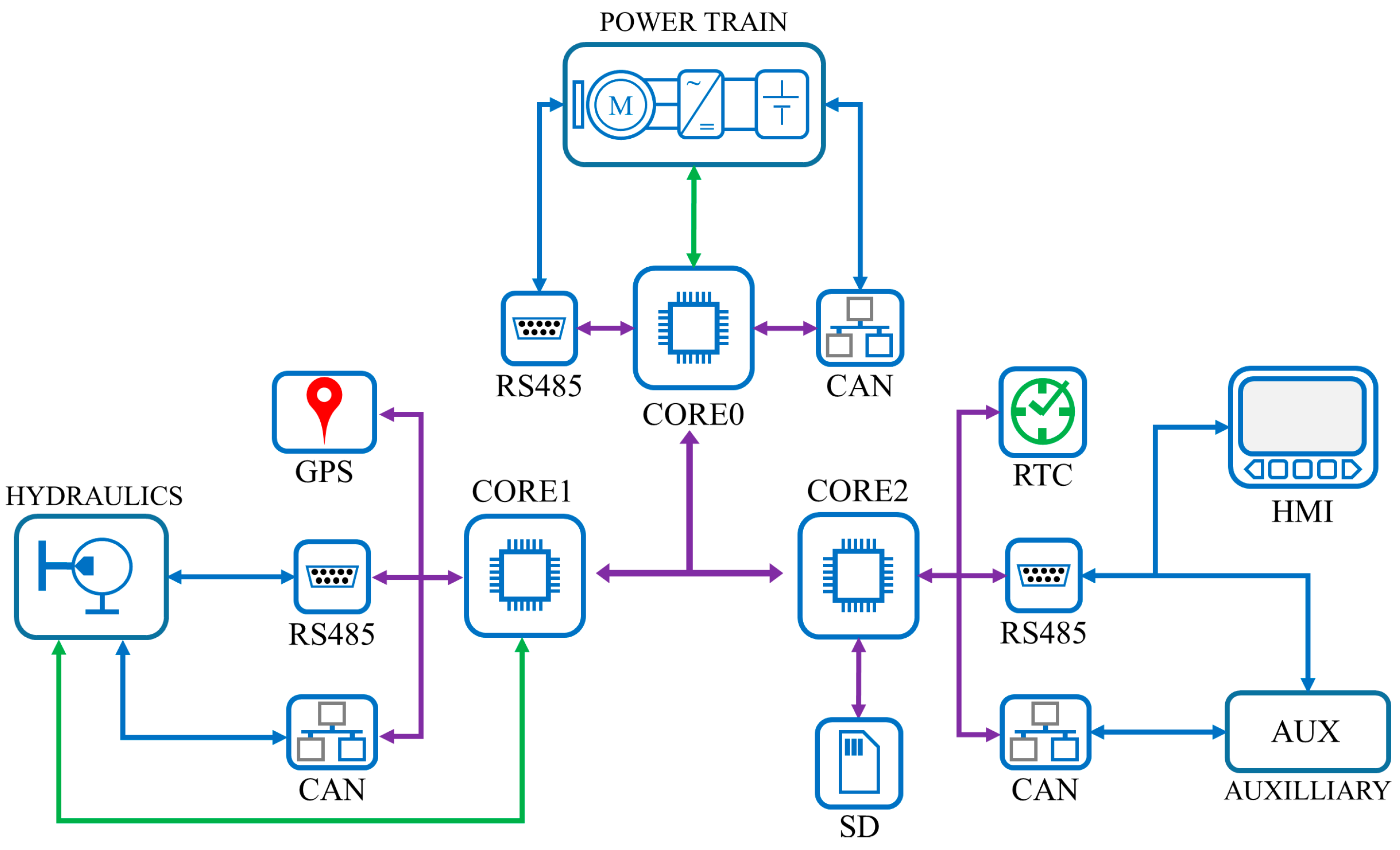
An electronic control unit (ECU) is responsible for managing all the subsystems of specific electrical equipment. An electric tractor is a complex machine with many systems requiring different regimes of operation. At a basic level, an electric tractor can be divided into three major subsystems, individually operated, as presented in
Figure 1:
Power train—composed of the battery or fuel cell, the power converter, the electric motor, and the battery management system (BMS);
Hydraulic system—composed of the hydraulic pump, control valves, hydraulic actuators, proportional valves, oil tank, and cooling system;
Auxiliary systems—composed of the security system, GPS, trip memory, the human–machine interface (HMI), window and climate control, computer interface, and/or Wi-Fi connectivity.
Each subsystem is monitored and controlled by a different microprocessor (identified in the figure as CORE0-2) that implements software-specific procedures. The three microprocessors and the specific interfaces are the basis for the electric tractor ECU. Internal and external ECU communication is provided by a series of RS485 and CAN serial buses. In addition, an internal high-speed serial peripheral interface (SPI) and inter-integrated circuit (I2C) interface connect different hardware devices to the different microprocessors. External input/output connections are also present to control specific equipment, along with analog inputs that are used to connect the various sensors aboard the electric tractor.
Furthermore, these three systems working independently provide better operation, and tasks will produce less of an influence on others; for example, an obstacle for the traction system will not affect the hydraulic system or the auxiliaries.
This architecture gives the ECU great flexibility when it comes to hardware compatibility, the multitude of communication, and input–output connections, making it so that new functions can be added or removed from the tractor with ease; the only element requiring adjustment is the software interface for the newly added component.
The three-core architecture allows for simpler software design since the functions that govern a certain system can be grouped; this also allows for better computational loading of the ECU.
2.1. ECU Software Architecture
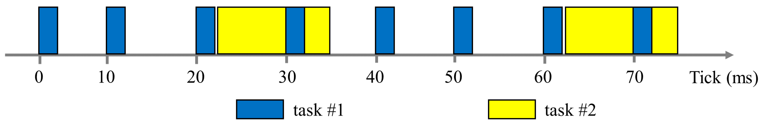
The three microprocessors share a common software architecture which is a cooperative multitasking system [
18,
19,
20], with task priority assignment. The operation of this type of task system is shown in
Figure 2.
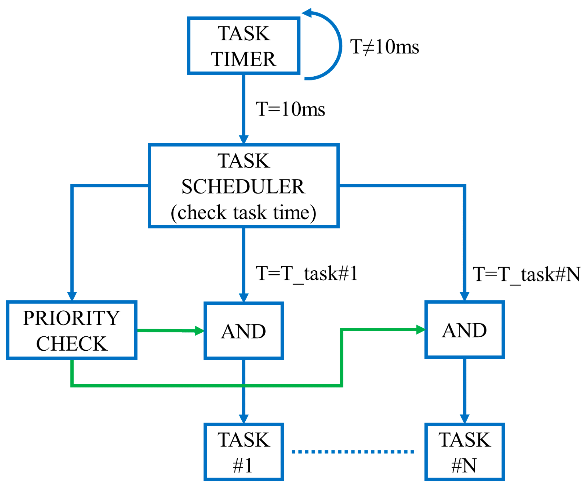
In
Figure 3, the main state diagram of the cooperative multitask system is presented, where every time the task timer reaches 10 ms, it signals the task scheduler to execute the tasks based on the priority check.
The cooperative multitask system has a tick rate of 10 ms; at each tick, a task scheduler decides what tasks are to be executed and in what order. At every tick, task #1 is executed and completed since its duration is less than 10 ms. Task #2 is executed at every five ticks, but it takes more than 10 ms to complete its execution; on the next tick, there will be a conflict as to which task to execute first, task #1 or task #2. In this case, the scheduler determines the priority of each task and executes the one with the highest priority.
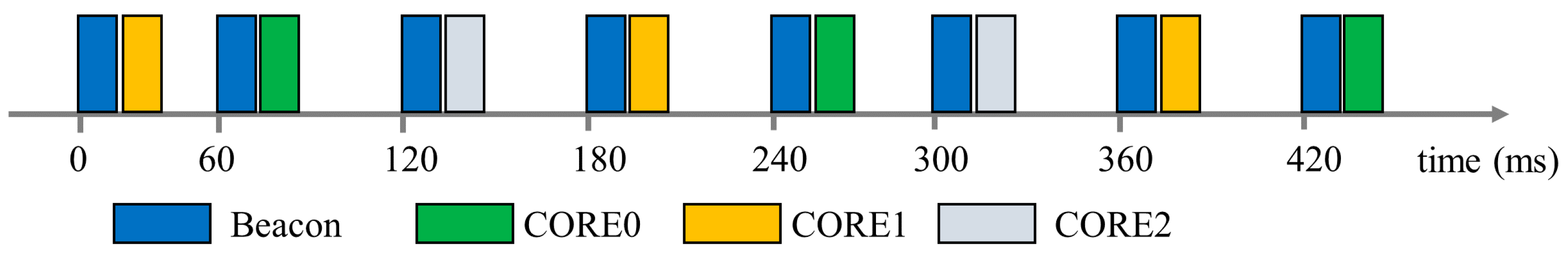
Communication between processors and/or external equipment is realized by an RS485 serial network. The communication protocol is implemented as a beacon protocol where only one device is actively communicating at any given time. The basic diagram of this type of protocol is given in
Figure 4.
Each 60 ms period, a beacon data packet is sent on the RS485 network which indicates which one of the microprocessors is allowed to communicate its data. This ensures organized communication and avoids data conflict on the serial network.
The communication is realized in hierarchy levels as follows:
L1 is the base level, where the data packet is sent across the communication cable; it consists of UART interrupts that transmit and receive data.
L2 is the level where data is assembled into a serial packet; checks are also performed here to establish if the system has permission to communicate.
L3 is the highest level and consists of a state machine that controls at what times the different processors can communicate with each other.
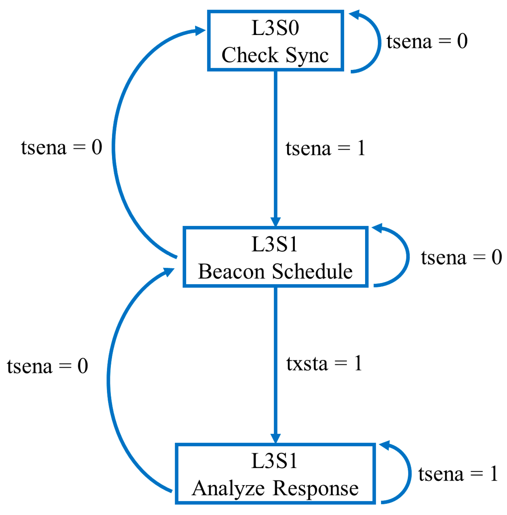
The diagram for the L3 level is presented in
Figure 5.
In
Figure 5, the L3 diagram has three states:
L3S0 is the state in which confirmation of the beacon synchronization mechanism is acknowledged.
L3S1 is the state in which the beacon data packet is generated, which is used as a pointer inside a predefined table that indicates which processor is allowed to communicate its data on the RS485 bus. After each beacon, a bit flag called txsta (transmission status) is set to 1, to indicate that a response is coming up next so no other communication can be initiated on the bus.
L3S2 is the state in which the response from each processor is acknowledged and analyzed.
In each state, the flag tsena (time slot enabled) is checked to confirm if the beacon synchronization is working properly. This is a safety mechanism that guards against undesired data on the serial bus.
2.2. Power Train Control
The power train is the system responsible for powering and moving the entire electric tractor; its main components are as follows:
Li-ion batteries;
Battery management system;
Electric motor with permanent magnets;
Power inverter;
External battery charger.
In the case of the electric tractor, the battery is of the Li-ion type with 144 V DC rated voltage, 120 A DC peak current, and 18 kWh capacity. The battery is monitored by an Orion BMS that performs cell balancing and thermal monitoring. This BMS has a built-in CAN bus for communicating with a battery charger and with other external devices, and it can be configured to communicate a wide range of parameters, such as cell voltages, pack current, state of charge (SOC), cell temperature, and cell resistance.
The power inverter is a Curtis converter with a rated voltage of 144 V DC and 500 A AC maximum output current; it has advanced algorithms for the efficient control of induction motors or permanent magnet motors and is equipped with a CAN bus interface. The converter supplies power to an AME200 permanent magnet motor with 16 kW rated power, 170 A AC phase current, and a rated speed of 3000 rpm, which comes equipped with an encoder with 64 teeth and a temperature sensor that can measure a maximum of 300 °C.
The battery charge is type 6.6 HK-J OBC, which has a rated power of 6.6 kW and is supplied from a 230 V AC, 32 A AC power outlet. The charger is also equipped with a CAN bus for communicating with the BMS.
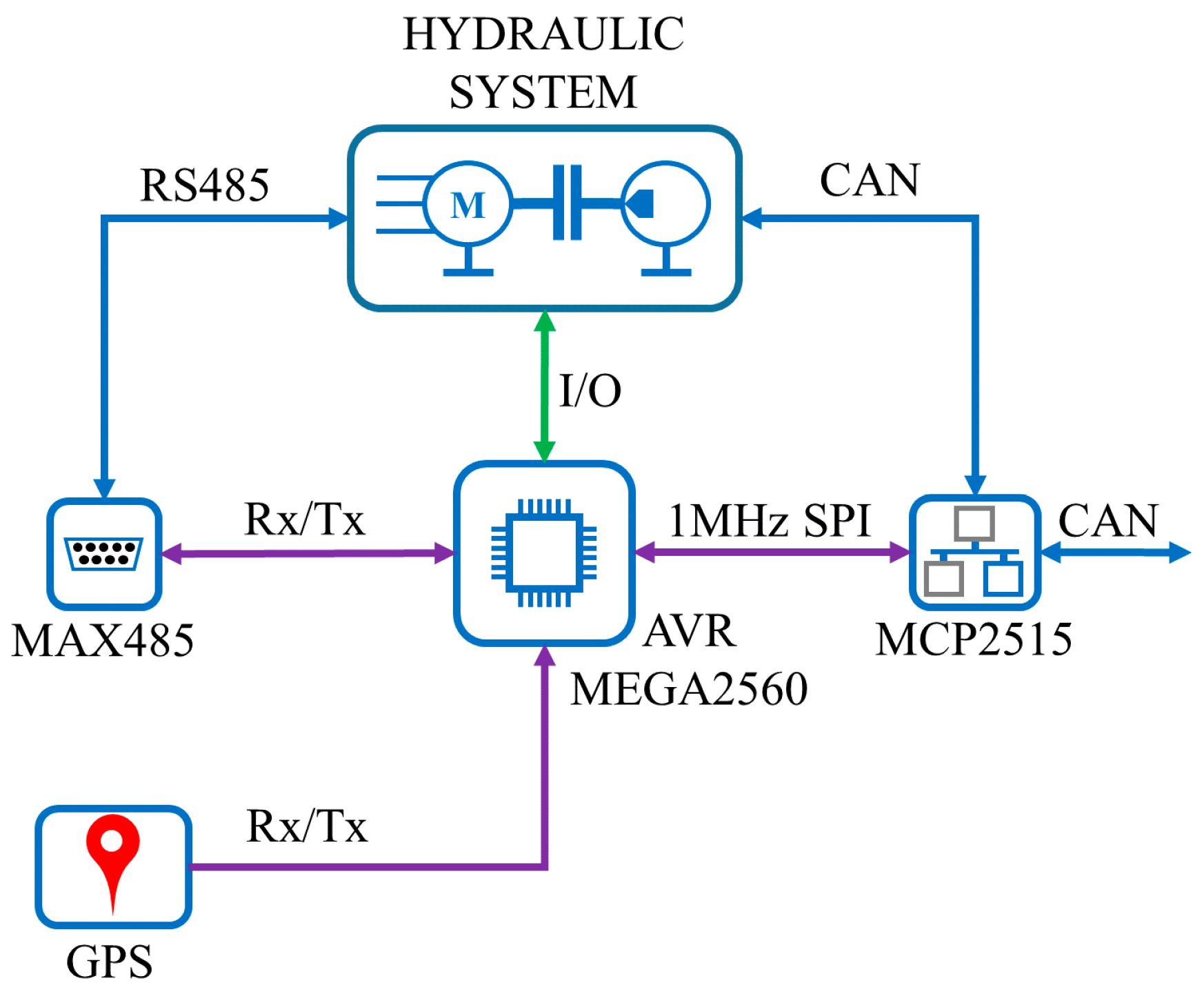
The hardware of CORE0 is responsible for interfacing with the power train and consists of an AVR Mega2560 microprocessor, an MCP2515 CAN bus transceiver with an SPI interface, a MAX485 serial interface, and a 12 V DC to 9 V DC power supply. The basic connections are presented in
Figure 6.
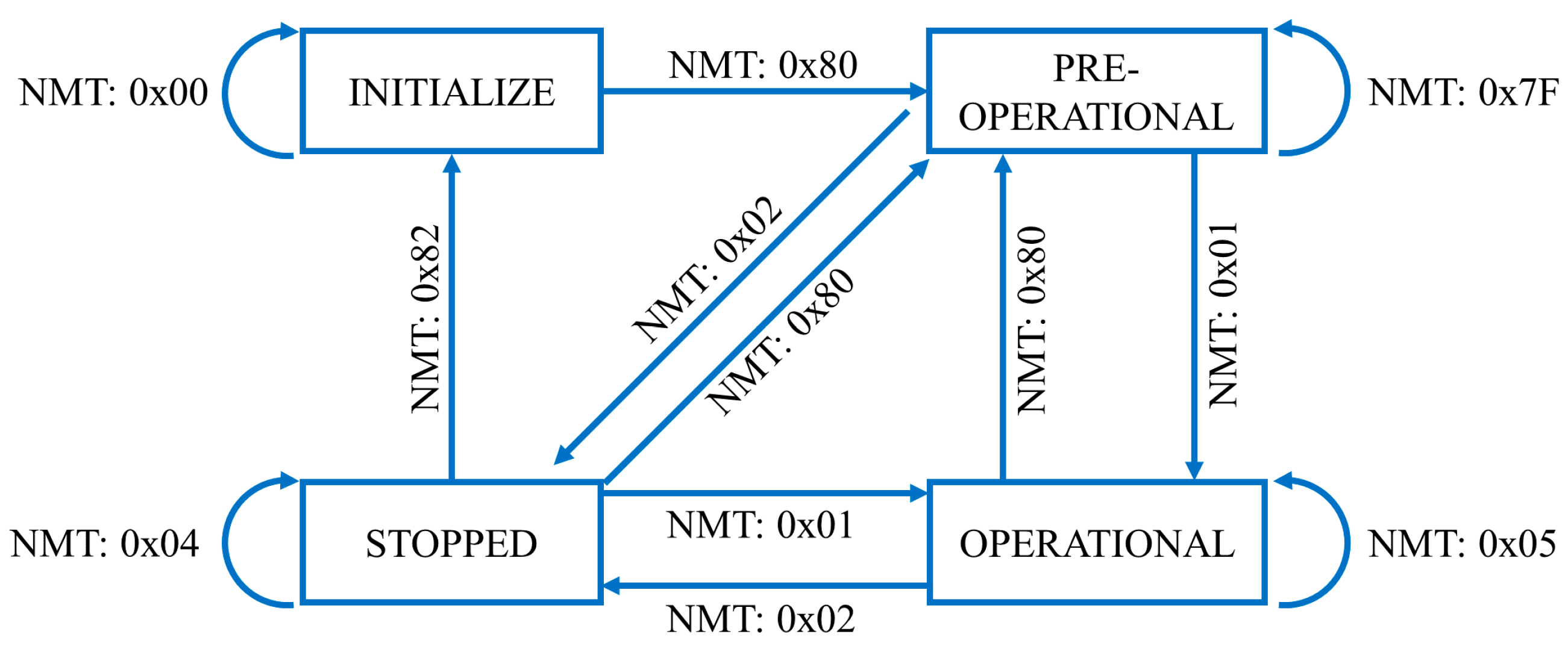
The protocol used by the inverter is CANOpen, [
21], which is a CAN bus communication protocol and device profile specification for embedded systems used in automation, and consists of an addressing scheme, several small communication protocols, and an application layer defined by a device profile. CANOpen uses network management protocols (NMTs) to issue state change commands to start, stop, and detect devices on the network. The CANOpen state machine is presented in
Figure 7.
The state machine in
Figure 7 has to be in the operational state so that the microprocessor has access to the object dictionary of the inverter. To enable the operational state, the software has to perform the following steps:
From pre-operational to operational state—send NMT command code 0x01; the NMT data packet has the structure: COB_ID D0 D1, where COB_ID: 0x000, D0: 0x01—command byte to switch to operational state, D1: 0x26—inverter identifier;
Check for NMT state code 0x05 on the heartbeat data packet, where the heartbeat is a special CANopen protocol, and has the structure COB_ID D0, with COB_ID: 0x700 + inverter identifier, D0: 0x05—current state (operational).
After receiving confirmation of the operational state code, data exchange is possible with the inverter using service data object (SDO) messages. The relevant parameters monitored are summarized in
Table 1.
The description of the command Byte 0 is given in the CAN in Automation CiA-301 specification [
21]. As an example, the CAN message that requests the DC voltage has the following structure:
CAN id: 0x626,
Byte0: 0x47 (ccs = 010—request data from inverter),
Byte1,2: SDO index with little endian notation—0x4C, 0x32,
Byte3: SDO sub-index = 0x00,
Full CAN message to request DC voltage: 0x626 0x47 0x4C 0x32 0x00.
The acceleration command and brake command come from external pedals that have analog signal outputs which are sampled by the microprocessor and modified according to imposed acceleration and deceleration limits to produce the necessary throttle command for the inverter.
The protocols used by the BMS and the battery charger are both generic CAN with the possibility to configure which data are sent to the ECU. The BMS is configured with the proprietary Orion BMS2 Utility application to send a CAN message with the following format:
CAN message time: 104 ms,
CAN id: 0x6B0,
Byte0,1: Pack Current—16-bit value, with 0.1 A/bit scaling factor,
Byte2,3: Pack Voltage—16-bit value, with 0.1 V/bit scaling factor,
Byte4: State of Charge SOC—8-bit value, with 0.5 scaling factor,
Byte5,6: Maximum pack temperature—16-bit value, with 1 °C/bit scaling factor,
Byte7: Checksum for data integrity.
The BMS is also configured to communicate with the charger by sending the maximum charge voltage and current, in addition to a start/stop charging signal. The charger itself sends a CAN data packet at 1-s intervals, with the output voltage and current, as well as its internal state. In
Table 2, the messages exchanged among the BMS, the charger, and the ECU are presented.
In
Table 2, the bytes of the BMS to ECU packet have the following meaning:
IBAT(H), IBAT(L)—high and low bytes of the battery pack current;
VABT(H), VBAT(L)—high and low bytes of battery pack voltage;
SOC—state of charge of the battery;
TMAX(H), TMAX(L)—high and low bytes of the maximum pack temperature;
CS—checksum for data integrity.
The BMS to charger packet bytes have the following meaning:
VCM(H), VCM(L)—high and low bytes of the maximum charging voltage;
ICM(H), ICM(L)—high and low bytes of the maximum charging current;
CHG—0—start charging, 1—stop charging.
The charger to ECU packet bytes has the following meaning:
VO(H), VO(L)—high and low bytes of charger output voltage;
IO(H), IO(L)—high and low bytes of output charger current;
STATE—charger state.
Through the digital I/O, the microprocessor controls the contactors of the battery and the inverter on the basis of the data it receives from both equipment. In this way, separation in the case of faults or other errors can be quickly achieved.
2.3. Hydraulic Control
The hydraulic system of an electric tractor consists of actuators and proportional valves that control different agricultural equipment such as forks or plows.
The hardware of CORE1 is responsible for interfacing with the hydraulic system and consists of an AVR Mega2560 microprocessor, an optional MCP2515 CAN bus transceiver with an SPI interface, and a MAX485 serial interface. Moreover, because the update speed of the GPS signals is slow compared to the other systems, it was decided that the receiver would also be connected to this processor; the basic connections are presented in
Figure 8.
The hydraulic systems can be controlled in several ways depending on the current equipment on board the tractor. The ECU is equipped with both I/O lines and serial communication that facilitate the interconnection of this external equipment.
The hydraulic inputs are represented by five digital input signals:
hydraulic pump START/STOP—which activates the hydraulic pump;
hydraulic actuator UP—controls an actuator moving up;
hydraulic actuator DOWN—controls an actuator mowing down;
hydraulic motor ON/OFF—enables a hydraulic motor;
hydraulic motor throttle—controls the speed of the hydraulic motor.
The pump is driven by a separate electric motor at a constant speed, while the actuators are controlled with solenoid valves, and the hydraulic motor is controlled by a proportional valve. The solenoids can be powered from 12 V DC or 24 V DC.
The GPS receiver is a Digilent PmodGPS (Pullman, WA, USA) which features the GlobalTop FGPMMOPA6H GPS (Tainan, Taiwan) antenna module and utilizes the MediaTek GPS MT3329 (Hsinchu, Taiwan), this receiver follows the NMEA-0183 standard [
22] by default. Communication with the processor is realized through a TTL UART interface, and the receiver is powered from 5 V DC.
For our purposes, the only output message of interest is the GPRMC message [
22], which contains the universal time counter UTC, date, position, course, and speed data in one single message. The description of this message is presented in
Table 3.
The symbols
$, *, and /r/n from
Table 3, are representing, according to the NMEA standard, the GPRMC message,
$ being used as Start_of_frame character, * used to indicate the start of checksum, and /r/n are the End_of_Message characters for the GPRMC messages.
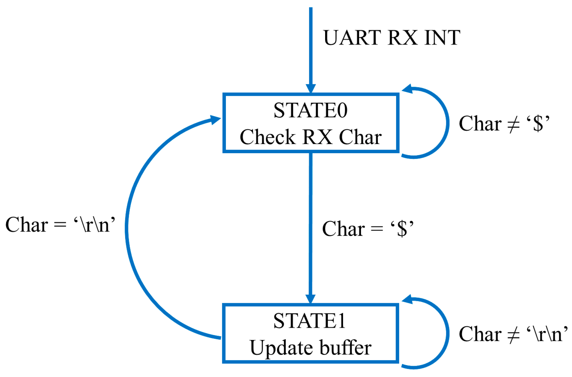
The microprocessor reads the GPS message on a separate UART interrupt, using a state machine. The state diagram is presented in
Figure 9.
The GPS state machine consists of two states:
STATE0—a character is read and, if it is equal to the $, which is the start character of a GPS packet, it will change to STATE1; otherwise, it remains in STATE0;
STATE1—a buffer is set up and characters received are loaded in this buffer. A running count of the number of charters received is also updated. According to
Table 3, if the sequence \r\n is received, which indicates the end of the GPS data packet, the buffer will be validated, and the state will change back to STATE0.
The GPS buffer will then get passed to the multitasking system for processing and extraction of data. The information is used for localization, as well as timekeeping or real-time clock corrections.
2.4. Auxiliary Systems Control
The auxiliary system of the electric tractor consists of the headlights and taillights, cabin AC control, the human–machine interface HMI, the event memory, and other such auxiliary devices.
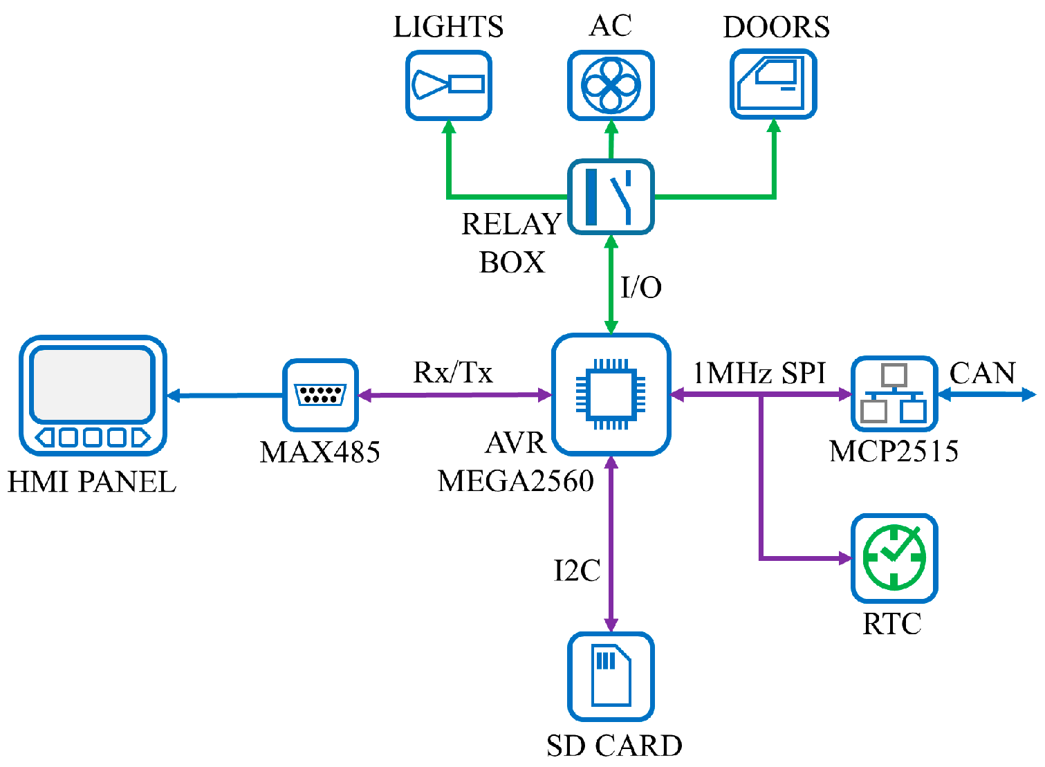
The hardware of CORE2 is responsible for interfacing with the auxiliary systems and consists of an AVR Mega2560 microprocessor (Houston, TX, USA), an optional MCP2515 CAN bus transceiver with an SPI interface, a MAX485 serial interface, a real-time clock circuit, (RTC), an SD card interface, and a 12 V DC to 9 V DC power supply. The basic connections are presented in
Figure 10.
The HMI consists of a 7-inch touch panel, supplied from a 24 V DC, 10 W power supply, that displays the data received from the power train, the hydraulic system, and the auxiliary systems. It can also be used to configure various parameters of the tractor. In the case of the used HMI, the programming was conducted using the proprietary software supplied by the manufacturer.
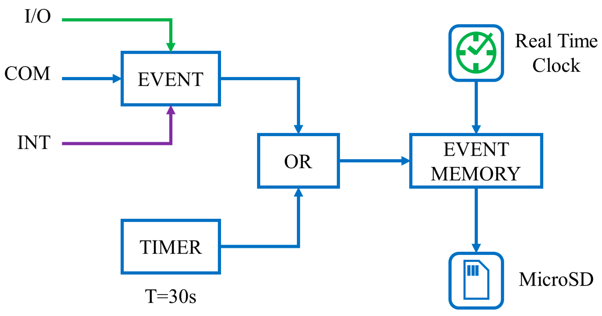
The event memory is used to help with the diagnostic of the tractor. It is a software-implemented function that saves data to a local SD card, as seen in
Figure 11.
The event memory is set up so that it will record any event from the I/O, from the communication interface COM, or from internal memory INT. Furthermore, at an interval of 30 s, a record is saved even if nothing has changed in the event memory. When one of these conditions is met, a recording is saved on the SD card containing the time stamp of the event, the event itself, and a list of other variables considered important. The time stamp is generated by an RTC type DS3231 that comes equipped with a 3.3 V DC battery backup. The RTC communicates with the processor by using a 400 kHz I2C interface, while the SD card uses a 1 MHz SPI interface. Both circuits are powered from 5 V DC.
Other devices such as headlights, taillights, external cameras, door locks, or cabin AC can be controlled with standard relays with the I/O lines.
4. Discussion
An electronic control unit for a fully electric tractor is a control unit that is of a different type than those present in conventional electric vehicles because of additional auxiliary equipment specific to agricultural applications, based on specific hardware and software.
The authors presented the design and optimization of an electronic control unit for the electric tractor, emphasizing software design. The integration of devices such as GPS, modern communication interfaces like UART/RS485 and CAN, drive train and battery monitoring, real-time monitoring of hydraulic operating parameters, trace memory functionality for diagnosis, and modern human–machine interface HMI was also presented.
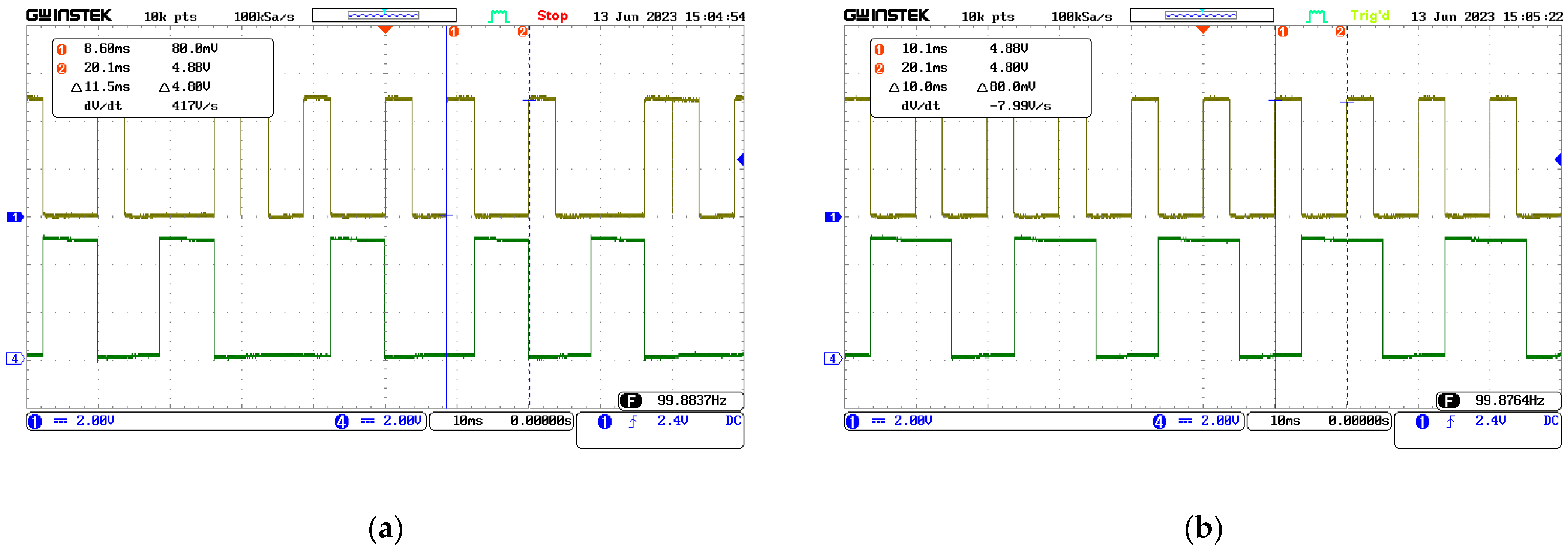
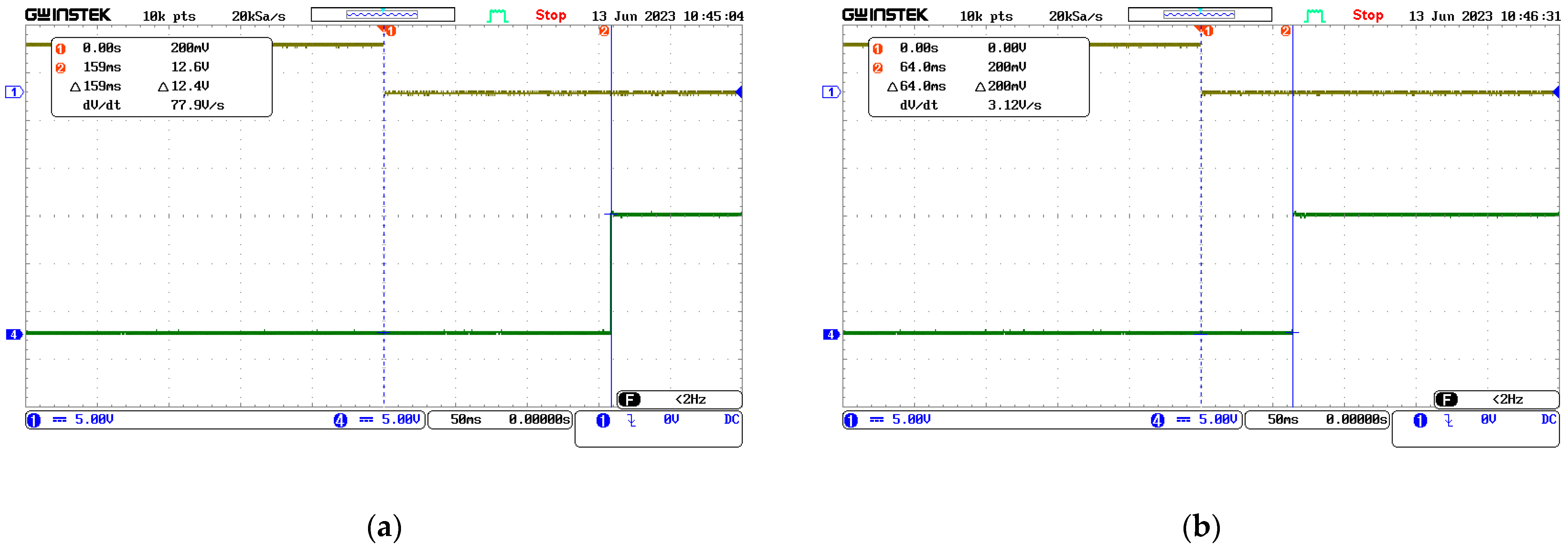
The experiment was focused on electronic control optimization, aiming at a faster and more reliable control loop for the power train, simple and predictable control of the hydraulic pump, and a simpler interaction with the auxiliaries. The optimization of the control system ensures different control loop timings for the major tasks, as the power train has a 60 ms control loop, the hydraulic system is operated at 180 ms, and the auxiliary systems are monitored at 960 ms. As shown in
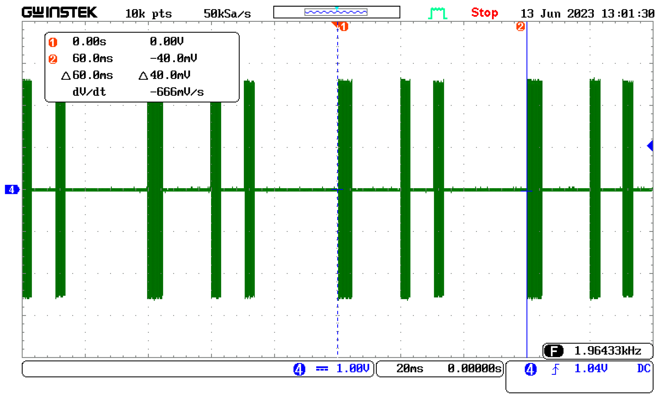
Figure 13a, software optimization allows a reduction in the loop from 11.7 ms to 10 ms, and assigning a higher priority to task 1 over task 2 permits the correct execution of both tasks while keeping the communications synchronous with the system tick. Regarding predictable delays in executing low-speed commands for the hydraulics, a solution was presented, consisting of improving the communication protocol by including the hydraulic unit command in the beacon message itself, and ensuring that the maximum delay time for the command is below 100 ms, as presented in
Figure 14. Another improvement using software measures is presented in
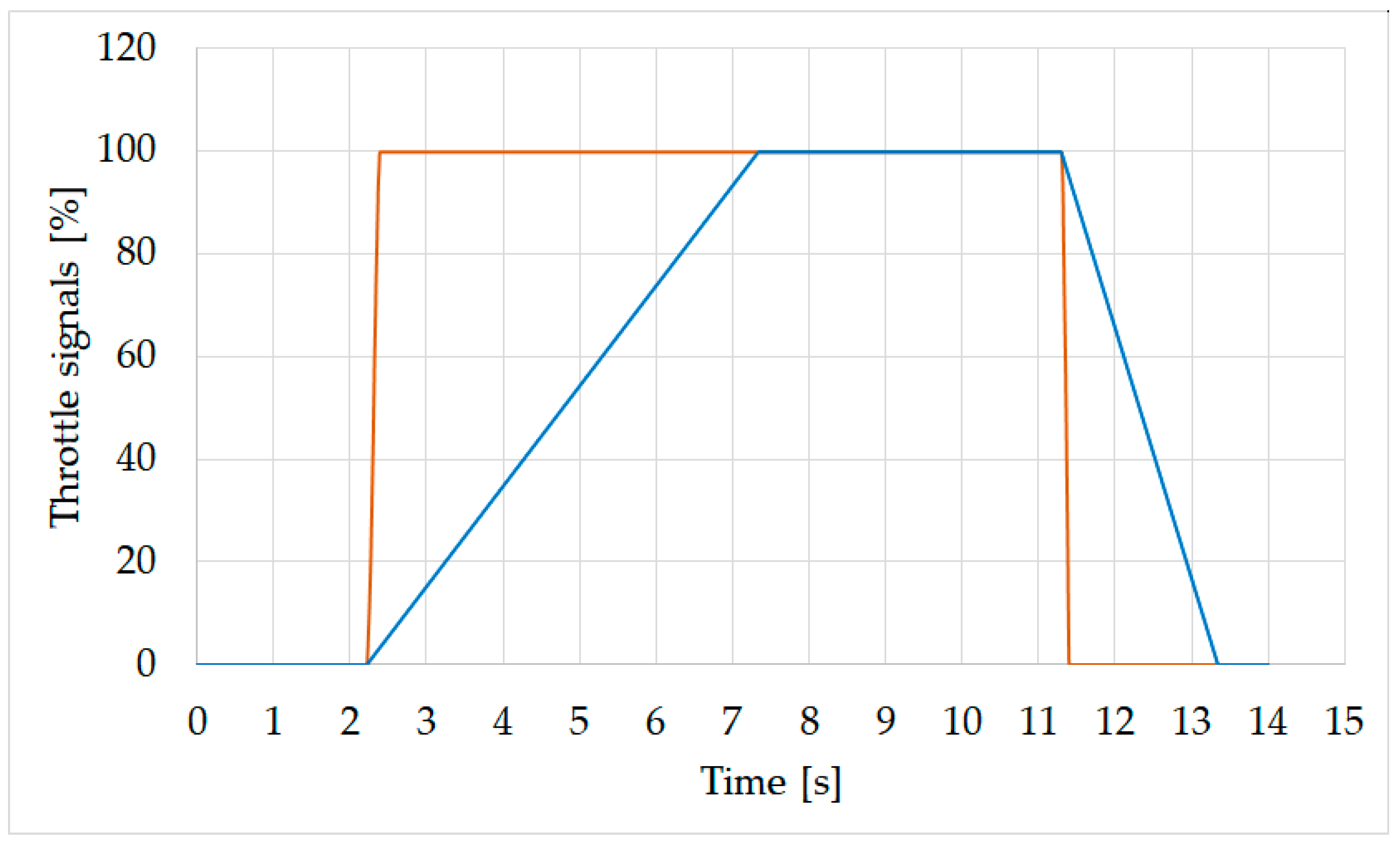
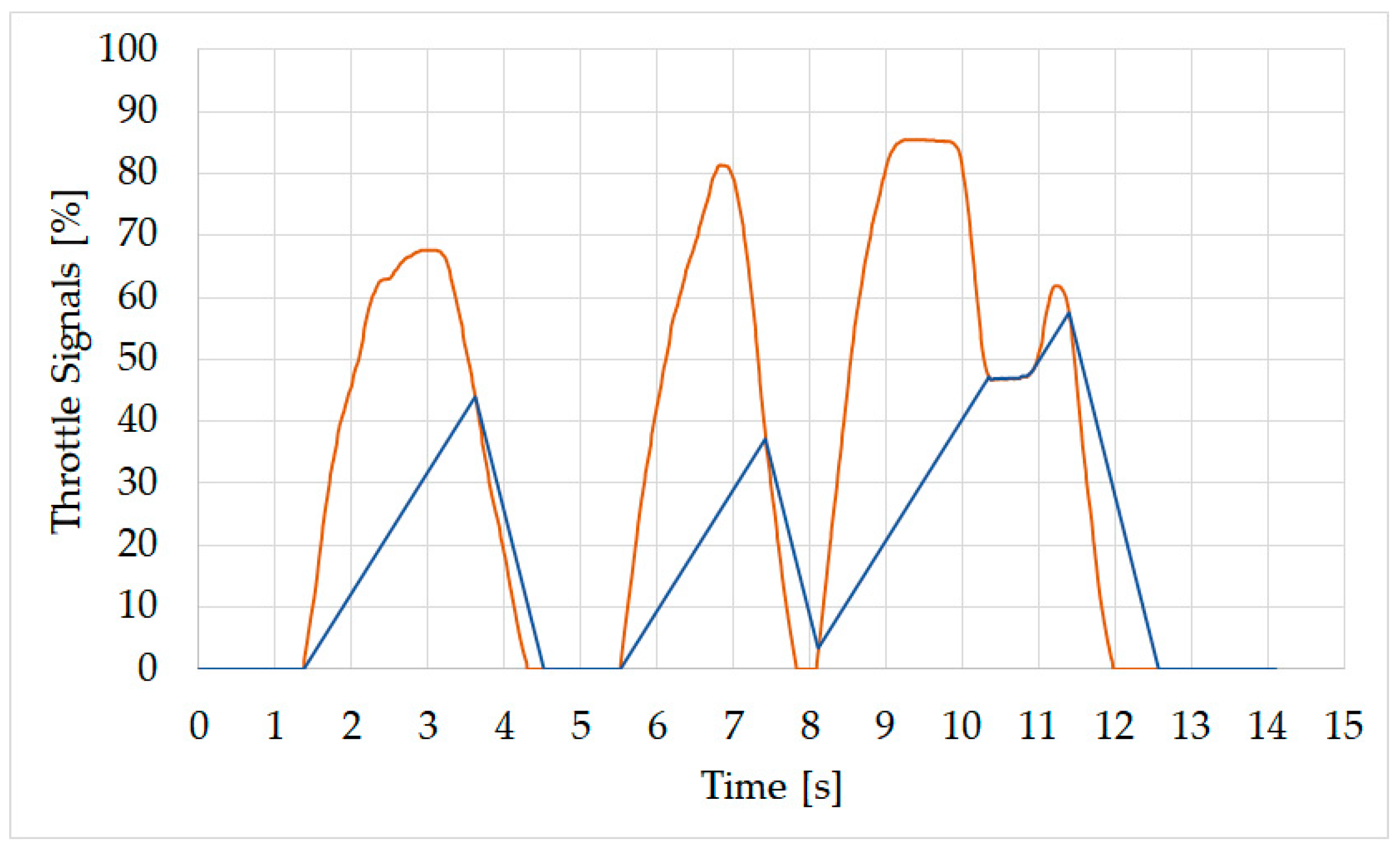
Figure 16, where the throttle of the vehicle is smoothed by a particular type of integration which ensures a throttle rise from 0% to 100% in 5.07 s and a deceleration from 100% to 0% in 2.1 s, for the protection of the mechanical transmission parts and the comfort of the driver.
Future research can be directed at developing a new electronic control system with two microcontrollers on the same electronic board, having multiple I/O, and providing serial communication channels for mitigation of the timing of the inter-microprocessor communications, thus making possible the reduction of the tick rate of the system and the improvement of diagnosis capabilities.
The final experimental model of such a control electronic unit can be used for other complex vehicles, such as harvesters and combines. Another possible application can be refurbishments applied to ICE buses to obtain electric buses and trolleybuses.
5. Conclusions
Agricultural vehicles, such as tractors, combines, and harvesters, seen as integrated systems, are complex machines with many systems that have to be interconnected for efficient functionality; thus, the need for a central control unit arises. This article presented an electronic control unit that interconnects the powertrain, the hydraulic systems, and the auxiliary systems of an electric tractor, with an emphasis on optimization through software design.
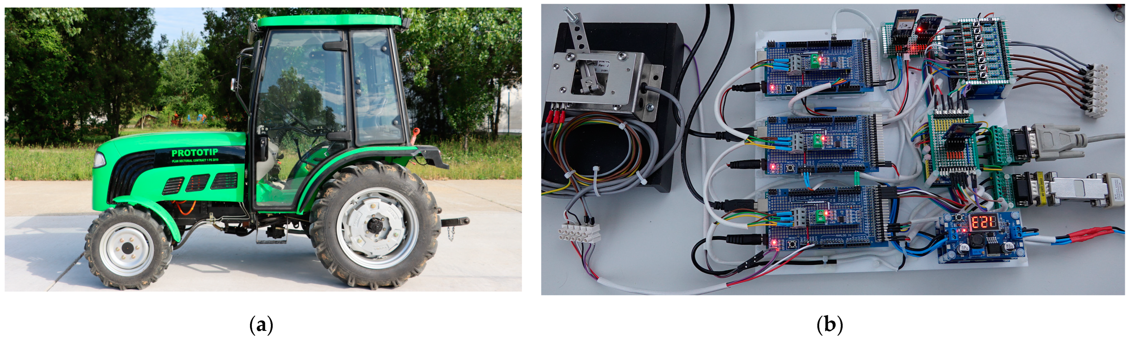
The article described, in brief, the hardware of the electronic control unit and details of the software state diagrams that are necessary to implement the functions required by the electric tractor. The experimental work was not performed on a real electric tractor, but we created the inputs on the electronic test system.
The results of this article showed how, through software optimization, the performances of the tractor can be improved, with parameters such as the response time of the various equipment being a useful indicator of such an improvement.


 ,
, 


