Article

Sinkhole Risk-Based Sensor Placement for Leakage Localization in Water Distribution Networks with a Data-Driven Approach

by
Gabriele Medio
,
Giada Varra
,
Çağrı Alperen İnan
,
Luca Cozzolino
* and
Renata Della Morte
Department of Engineering, University of Naples Parthenope, 80143 Naples, Italy
*
Author to whom correspondence should be addressed.
Sustainability 2024, 16(12), 5246; https://doi.org/10.3390/su16125246
Submission received: 15 May 2024 / Revised: 15 June 2024 / Accepted: 18 June 2024 / Published: 20 June 2024

Abstract

:
Leakages from damaged or deteriorated buried pipes in urban water distribution networks may cause significant socio-economic and environmental impacts, such as depletion of water resources and sinkhole events. Sinkholes are often caused by internal erosion and fluidization of the soil surrounding leaking pipes, with the formation of soil cavities that may eventually collapse. This in turn causes road disruption and building foundation damage, with possible victims. While the loss of precious water resources is a well-known problem, less attention has been paid to anthropogenic sinkhole events generated by leakages in water distribution systems. With a view to improving urban smart resilience and sustainability of urban areas, this study introduces an innovative framework to localize leakages based on a Machine learning model (for the training and evaluation of candidate sets of pressure sensors) and a Genetic algorithm (for the optimal sensor set positioning) with the goal of detecting and mitigating potential hydrogeological urban disruption due to water leakage in the most sensitive/critical locations. The application of the methodology on a synthetic case study from literature and a real-world case scenario shows that the methodology also contributes to reducing the depletion of water resources.

1. Introduction

Nowadays, the strategic management of water resources is imperative to meet the escalating demands of a continuously growing global population, a challenge exacerbated by the alarming reduction of water availability [1]. Ensuring uninterrupted and safe water provision is paramount for the sustainable management of drinking water distribution networks (WDNs) [2,3]. WDN pipes are required to convey water with appropriate quality, quantity, and pressure, from available sources to end-users [2], but the subsurface placement of pipes makes them highly susceptible to progressive deterioration due to ageing and incorrect junction execution. This is a major concern, since many water supply infrastructures were installed more than 50 years ago [4]. Damaged or deteriorated pipes may lead to water leakage, with water escaping and flowing into the surrounding soil from the pipe joints and through longitudinal/circumferential cracks along the pipe [5,6]. Consequences of water pipe failures extend beyond WDN damage, leading to significant economic losses and broader societal or environmental impacts [2,7]. It has been estimated that the annual volume of water losses by water utilities worldwide amounts to about 126 billion m3, with a related cost of about 39 billion USD per year [8]. In Italy, the National Institute of Statistics (ISTAT) estimated that, in 2020, the total volume of water losses during the distribution to end users amounted to 3.4 billion m3, representing 42.2% of the water introduced into the network [9], with the most critical situations concentrated in the Central and Southern areas. Leakages in buried water pipelines may cause multiple additional problems, such as health-related issues (water contamination due to pathogen intrusion [10]) and the formation of sinkholes [11].
A very hazardous form of sinkhole is the cover-collapse sinkhole, which occurs by the sudden downward movement of soil, leaving an upward erosion behind [12,13]. The risk of Hydrogeological Disruption due to Leakage (HDL) in populated areas is well-documented. Among the causes that trigger anthropogenic sinkhole formation, we may find groundwater level fluctuations due to groundwater extraction [14,15], or roof failure of existing man-made cavities, such as catacombs, aqueducts, ancient quarries of bedrock materials [16,17,18], and extraction of minerals from underground coal mines [19,20]. However, urban sinkholes commonly originate from leaking WDNs, due to internal soil erosion and washing off of fine-sized sediments, or fluidization around the defective pipe [21,22]. These mechanisms can later result in the development of cavities and the collapse of the soil layer above the cavity [23,24].
Urban ground collapse incidents and sinkhole formation, attributed to water leakage from unexpected pipe failure, have been increasingly documented worldwide [24,25,26]. These phenomena are insidious because they often remain undetected until the final failure, i.e., until it is too late to intervene. Since the sinkhole usually occurs with no or few precursory signs, threats to human safety are possible (traffic accidents on the streets and human injuries on the sidewalks), leading also to capital losses from damage to buildings and utilities [26]. Given the ageing WDNs, issues related to water leakages from defective pipes are expected to aggravate [6]. For this reason, reducing, detecting, and locating, water losses due to leakage in underground pipes have become significant challenges for water management companies [11]. Sustainable water resources’ management requires an integrated approach encompassing different activities, such as infrastructure revamping, regular maintenance, and pressure management [5]. In addition to this, the implementation of monitoring and control systems for the timely identification of water pipe leaks is essential.
Optimal sensor placement (OSP) for leakage detection within a WDN is a major engineering issue. Casillas et al. [27] proposed a sensor placement that minimized the number of non-isolatable leaks. Steffelbauer and Fuchs-Hanusch [28] optimized the placement of pressure sensors for improved leak detection under uncertain user demands. In Cugueró-Escofet et al. [29], the deployment of the best sensor set for leak detection was based on a sensitivity matrix. To prioritize the detection of leakage events at nodes with higher leakage potential, Forconi et al. [30] proposed a risk-based method for optimal sensor placement in which a higher leakage probability was assigned to leakage events that can result in a greater leakage. For leak detection, Li et al. [31] used an OSP based on a semi-supervised strategy, i.e., they considered that some leak positions were unknown. Hu et al. [32] proposed an improved hierarchical algorithm for optimizing sensor placement that considered various failure scenarios to ensure that information loss is minimal when sensor failure occurs. Hu et al. [33] proposed a multi-objective optimization method for sensor placement that relied on risk-based leakage functions, aiming to minimize the various negative effects of a leak on the water distribution network. Cheng and Li [34] used a heuristic algorithm for OSP that took advantage of feature selection and graphical signal processing theory.
From this short literature review, it is evident that the researchers have devoted much attention to leakage reduction problems by considering the intrinsic characteristics of the WDN while neglecting extrinsic aspects, such as the leakage impact on the urban fabric due to sinkhole formation. The effect of leakages on the environment should not be underestimated, given the current standards of sustainability and resilience required by urban settlements [35,36].
For many years, the attention of researchers has mainly focused on the hazard, susceptibility and risk assessment of natural sinkhole formation with different approaches, including GIS (Geographic Information System) environment and machine learning techniques [37,38,39]. However, significantly less attention has been devoted to risk prediction and the formation of anthropogenic sinkholes, especially when caused by leaks in underground water pipelines in urban areas [40]. In some experimental studies [40,41], small-scale physical model tests have been performed to investigate soil erosion and ground collapse mechanisms due to leakage from sewer and/or water pipelines, with the aim of evaluating the risk of man-made sinkhole occurrence under different conditions. However, to the best of the writers’ knowledge, the existing literature seems to lack a comprehensive framework for the optimal positioning of monitoring sensors for the reduction of hydrogeological disruption risk (sinkhole formation and ground collapse due to leakages from urban WDNs).
The implementation of a monitoring system across the WDN of an entire municipality can be expensive and complex. Therefore, it is crucial to first identify the areas with a higher risk of sinkhole occurrence and ground subsidence due to water leaks. Monitoring these high-risk areas could optimize resource allocation, with saving of time, energy, and costs. In this paper, we present a novel methodology for OSP for leakage localization where the potential hydrogeological impact of leaks on the urban environment is considered. In the proposed framework, a Genetic Algorithm (GA) is used for the optimization of a set of sensors whose ability to localize the leakage is ensured by the application of a Machine Learning (ML) approach. During the optimization process, the impact of leakages on the urban fabric is considered based on the position of critical infrastructures and the population density distribution. The methodology is demonstrated through its application to (i) a case study from literature and (ii) a real-world case study involving the water distribution network of a municipality in Southern Italy.
The rest of the paper is structured as follows. Section 2 presents the proposed sinkhole risk-based methodology for the localization of leaks. In Section 3, two applicative examples are shown, and the corresponding computational results are discussed. Finally, the study conclusions are outlined in Section 4. Appendix A, which demonstrates the benefits of Principal Component Analysis, and a Nomenclature, reporting the symbols’ meaning, complete the paper.

2. Materials and Methods

In this section, we present the methodology used to find the optimal set of pressure sensors able to minimize the hydrogeological risk caused by leaks in WDNs (see Figure 1). In detail, this process is based on four elements:
  • WDN zoning based on the risk from Hydrogeological Disruption due to Leakage (HDL) (Figure 1, step 1);
  • Use of a hydraulic simulator to generate WDN pressure data under different demand conditions and different leakage scenarios (Figure 1, step 2);
  • Use of a GA for the approximate solution of the OSP problem, aiming at maximizing the likelihood of detecting leakages in areas at higher risk from HDL (Figure 1, step 3);
  • During the GA application, use of an ML model to train and evaluate the sets of sensors, i.e., the candidate solutions of the OSP problem (Figure 1, steps 3–4).
The risk evaluation approach is discussed in Section 2.1, while the data generation process is presented in Section 2.2. Finally, the approximate solution to the OSP problem is discussed in Section 2.3.

2.1. Risk Evaluation of Hydrogeological Disruption Due to Water Leaks

The WDN pipes flank and cross structures and infrastructures with different economic and strategic values. For this reason, the risk associated with sinkholes caused by leaks in WDNs depends on the leak location itself.
The risk quantification should consider:
-
the hazard H: the likelihood of occurrence of the dangerous event, i.e., the hydrogeological disruption caused by a non-detected leak with a given magnitude at a given location, ranging from 0 (null likelihood) to 1 (maximum likelihood);
-
the vulnerability V: the expected degree of damage due to the impact of the hazardous event (hydrogeological disruption due to leakage) on the system (soil, urban infrastructures and human elements), ranging from 0 (no damage) to 1 (total disruption) [39];
-
the exposure E: the socio-economic importance of goods, structures, and infrastructures, as well as the presence of people in the at-risk area.
Based on these factors [42], risk can be quantified using the following product:
R = H   · V ·   E  
In the present study, the risk is ranked on a scale of NR levels from R1 (lower risk) to RNR (maximum risk). If Ω = 1,2 , , N N   is the set of the NN junction nodes in the WDN, the function R(i) = Rj, with i ∈ Ω and j 1,2 , , N R , associates the level of risk Rj to the node i.
From the definition of Equation (1), the risk assessment of sinkholes related to possible leakage must be conducted through a detailed study of the characteristics of the WDN, soil, sinkhole formation mechanism, and urban elements exposed to potential disruption. Regarding natural sinkholes induced in urban areas by unstable travertine, an example of such a procedure is available in the literature [39]. We briefly comment on some difficulties that can be encountered in the case of leakage from damaged pipes in medium-large WDNs.
Vulnerability. The vulnerability, whose evaluation is often uncertain and complex, depends on the magnitude of the hazardous phenomenon and the resistance of the different elements at risk [39]. In our case, the vulnerability evaluation requires detailed information on the hydrogeological characteristics of the areas exposed to leakage, which is possible only if detailed identification of soil layers is available. This type of study mostly concerns limited areas, being hardly representative of the entire WDN vulnerability. On the other hand, geological maps provided by regional and national agencies do not have a resolution sufficient to derive detailed zoning.
Hazard. Hazard estimation can be carried out when historical information about the location and frequency of leaks, and the topological and hydraulic characteristics of the WDN, are available to derive correlations. This information is generally more readily available than vulnerability information.
Exposure. The exposure is the most easily calculable component of risk, regardless of the network under consideration, as it is related to the value of the elements prone to potential hydrogeological instability phenomena due to water leakage. Knowledge about the WDN topology and the analysis of the exposed element value in its immediate vicinity are sufficient to evaluate this risk component
In the present paper, without loss of conceptual generality, we adopt a numerical simplification by assuming that hazard H and vulnerability V are uniform over the territory. This implies that R = c·E, where c = H·V is a spatially uniform constant. Note that the assumption of uniform V is not unusual in the literature of sinkhole risk assessment [43] and risk evaluation of leakages in WDNs [30]. On the other hand, the assumption of uniform H may apply in the case that the information about the spatial distribution of pipe damage probability is absent or uncertain. For the sake of simplicity, H = 1 and V = 1 are assumed in the following, leading to R = E. The procedure for the evaluation of the j-th class of risk Rj is outlined in Section 3 considering two case study applications.

2.2. Pressure Data

This study utilizes synthetic hydraulic data generated with the open-source hydraulic simulation software EPANET 2.2 [44], developed by the U.S. Environmental Protection Agency (EPA). The availability of a dedicated library, Toolkit Python EPANET (EPyT), originally developed by the KIOS Research and Innovation Center of Excellence (University of Cyprus), allows the use of the Python programming language for the customized simulation of the various leakage scenarios and the creation of the corresponding dataset.
In the present study, the following simplifying assumptions are made for the scenarios:
-
leakages are considered at junction nodes only;
-
each scenario is characterized by a single leaking node;
-
the total number of leakage scenarios is equal to the number NN of junction nodes;
-
each leakage scenario is evaluated over a simulation time of T = 50 days.
For each leakage scenario, the generated dataset consists of the pressure values at junction nodes during the entire simulation time.

2.2.1. Demand Modelling

To produce the hydraulic simulations, we assume that each network junction node is characterized by variable demand during the day. The demand qi(t) (l/s) at the junction node i ∈ Ω and time t is given by the product of the node’s base demand qBi (l/s) by the demand pattern coefficient DC(t), which is variable during the day:
q i t = D C t   · q B i
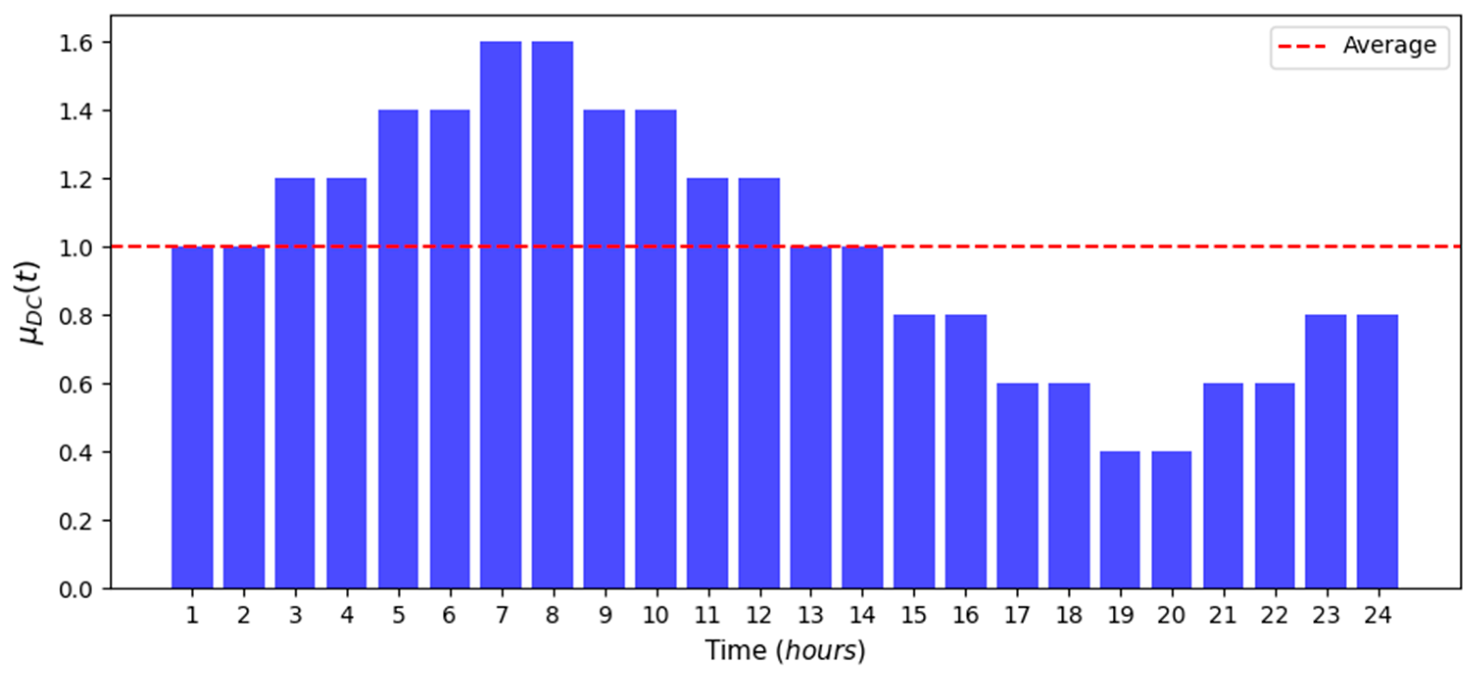
To consider the random component of the demand, the coefficient DC(t) has a log-normal distribution with a constant coefficient of variation CV = 0.2 [45], while the mean µDC(t) is variable during the day, as represented in Figure 2.

2.2.2. Water Leakage Modelling

The EPANET software does not exhibit a native function to simulate leakages. For this reason, emitters are often used in the literature to approximate the behavior of leakages at junction nodes [46]. The flow rate Qi (l/s) through the emitter at the junction node i ∈ Ω is a function of the piezometric head hi (m) at the same node, according to the following equation:
Q i = E C i · h i 0.5
where ECi (l/(s·m0.5) is the emitter coefficient of the i-th node [44,46]. In the literature, several works discuss the values of the emitter coefficient to be used for leak simulation [46,47,48,49].

2.3. Pressure Sensor Training and Optimal Positioning

The precise localization of leakages is a difficult task, due to the intrinsic uncertainties (demand, pipe roughness, network topology skeletonization) and the limited number of sensors that can be deployed in real-world cases. It is reasonable that leakage is localized when a sufficiently narrow set of junction nodes is correctly individuated as a possible origin of leakage. After the individuation of the interested area, the exact position of the leakage can be finally found by using on-field approaches, such as geophysical methods [50,51,52]. For this reason, the set Ω of the WDN junction nodes is usually subdivided into NC non-overlapping subsets Ωk called localization clusters, which are defined based on relative proximity, network topology, and level of risk. Given a set P = P 1 , P 2 , . . , P N S   of NS pressure sensors, with Pk ∈ Ω, we assume that the scenario leakage from the node i ∈ Ω is correctly localized when the set P of sensors detects a leakage originating from the cluster Ωk containing the node i. In the present paper NC = NN, meaning that no node clustering is assumed.

2.3.1. Data Pre-Processing

To improve the Machine learning model performance, the pressure data must undergo a series of pre-processing steps before being used in the training phase [53]. In the present case, the pre-processing steps include data partitioning into test and training sets, data scaling, and Principal Component Analysis (PCA).
Machine learning models construct the relationships between input and output data using the training set, while the test set, not involved in the training phase, is applied to evaluate the accuracy of model predictions. For the present study, a stratified partitioning was performed, with 20% of the data used as a test set and 80% as a training set, to ensure that both the test and training sets have a balanced representation of all target classes under consideration.
Data scaling aims at improving the performance of machine learning algorithms. In this study, the standardization technique is used to constrain the features to have a null mean and a unitary standard deviation, using the following equation:
h s t , i = h i μ h i σ h i
where μ h i and σ h i are the mean and standard deviation of non-standardized nodal pressure hi and hst,i is the corresponding standardized value.
Finally, Principal Component Analysis (PCA) is applied. The goal of PCA is to construct a meaningful basis to reformulate the data [54], disclosing the hidden structure of the dataset by reducing its dimensions and filtering data noise. The reader is addressed to Appendix A for further details. In the present application, the process is carried out using the Singular Value Decomposition (SVD) [55,56,57].

2.3.2. Decision Tree Classifier

An appropriate algorithm must be used to enable the detection and the localization of leakages. To this aim, different classification algorithms (Random Forest, Support Vector Machine, Neural Networks, etc.) have been used in the literature [58,59,60,61,62,63,64,65]. In this study, the Decision Tree (DT) is applied. The DT model used for the leak localization performs supervised learning, which requires a data set containing both features and corresponding labels (desired output). In the present case, the labels represent the leaking node, while the features related to a given label are the pressures recorded at the sensor nodes in the presence of the leakage (see Section 2.2).
The DT approach is based on the use of three logical elements, nodes, branches, and leaves. The nodes represent the decision points, while the branches represent the outcome of a decision by connecting the tree nodes. Finally, the leaves represent the output of the model. In the present work, the DT training uses the Gini criterion to partition the training set and find the features that better separate the target classes (the leakage scenarios). The partitioning of the dataset is carried out until all the leaves are pure, i.e., when they contain pressure values belonging to only one class, or the number of samples per leaf is less than a given threshold (assumed equal to 2). Finally, each leaf is associated, based on its content, with one of the leakage scenarios. Once the DT is trained, it can be used to make leakage location predictions based on the pressure values belonging to the test set.
The localization accuracy Mk(P)
M k P = N A k ( P ) N k
is used in the following to approximate the probability that the set P of sensors correctly identifies leakages originating from the nodes of the localization cluster Ωk in the test dataset. In Equation (5), NAk(P) is the number of accurate predictions made by the set of sensors P regarding the leakages originated from nodes of the cluster Ωk and Nk is the total number of leakage scenarios from the nodes of cluster Ωk.

2.3.3. Sensor Position Optimization

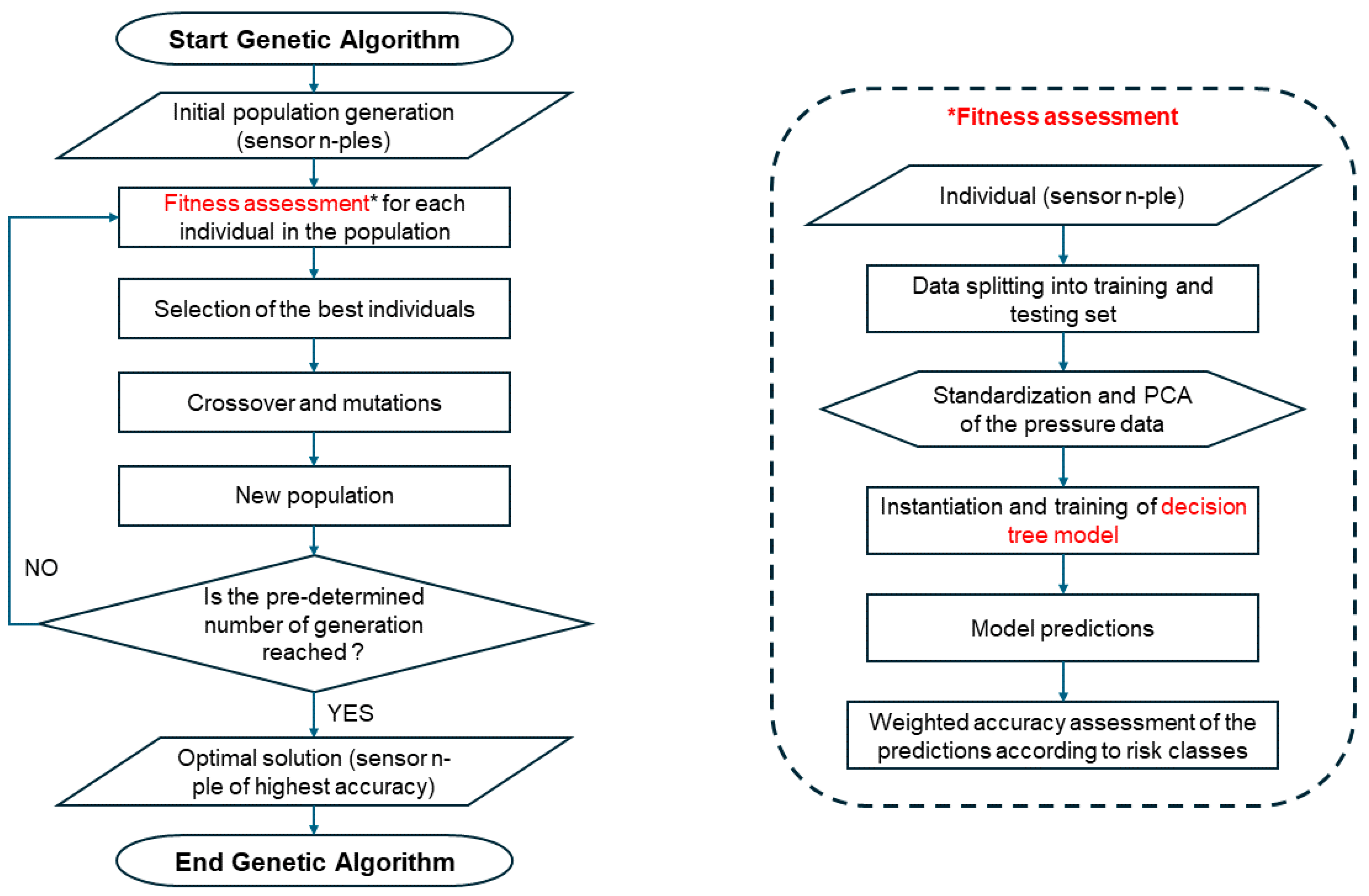
The Genetic Algorithm (GA) is a popular optimization approach inspired by Charles Darwin’s theory of biological evolution through mutation and natural selection [66]. The algorithm starts with a population of potential solutions (called individuals) that are evaluated in terms of their fitness; at each generation, the algorithm selects the best individuals and forms a new generation of individuals through crossover and mutation operators, improving the average fitness of the population and the fitness of the best individual. The process is repeated until no additional improvement is obtained because the fitness of the best individual stagnates.
In the present work, the generic individual is a set P of NS sensors whose fitness Mp(P) is defined as
M p P = k = 1 N C R Ω k · M k P k = 1 N C R Ω k ,
i.e., as the risk-averaged localization accuracy. For each generation, and for each individual, the cluster localization accuracy values Mk(P) are evaluated using the test dataset after training of the individual P within the process described in Section 2.3.2.
In Equation (6), the cluster risk Rk) attributed to the cluster Ωk is the averaged value of the nodal risks R(i) with i ∈ Ωk. The cluster risks act as weights, allowing the GA to optimize the position of the sensors by increasing the probability of localizing leaks in areas with high hydrogeological risk. The proposed formula is very generic and does not place any constraints on how the nodal risks R(i) and the metric Mk(P) are defined.
The GA process is outlined in Figure 3 (left column). The DT process used for training and evaluation of individuals is outlined in the right column of the same figure.

3. Results and Discussion

In this section, the methodology is demonstrated using a simplified WDN from the literature, the Hanoi network, and a real-world WDN of a municipality in Southern Italy, called Real Network 1. Risk assessment of water distribution networks to HDL requires the determination of hazard H, exposure E, and vulnerability V (see Section 2.1). Usually, the factors H and V are not readily available, while the exposure information is more easily collected based on census information and infrastructure delineation. Therefore, the procedure is demonstrated, in a preliminary way, by assuming that the hazard and the vulnerability are uniform over the territory taking H = 1, V = 1, and R = E (see Section 2.1). The procedure outlined in Section 2 is applied to the two case studies using the GA parameters of Table 1.

3.1. Hanoi Network

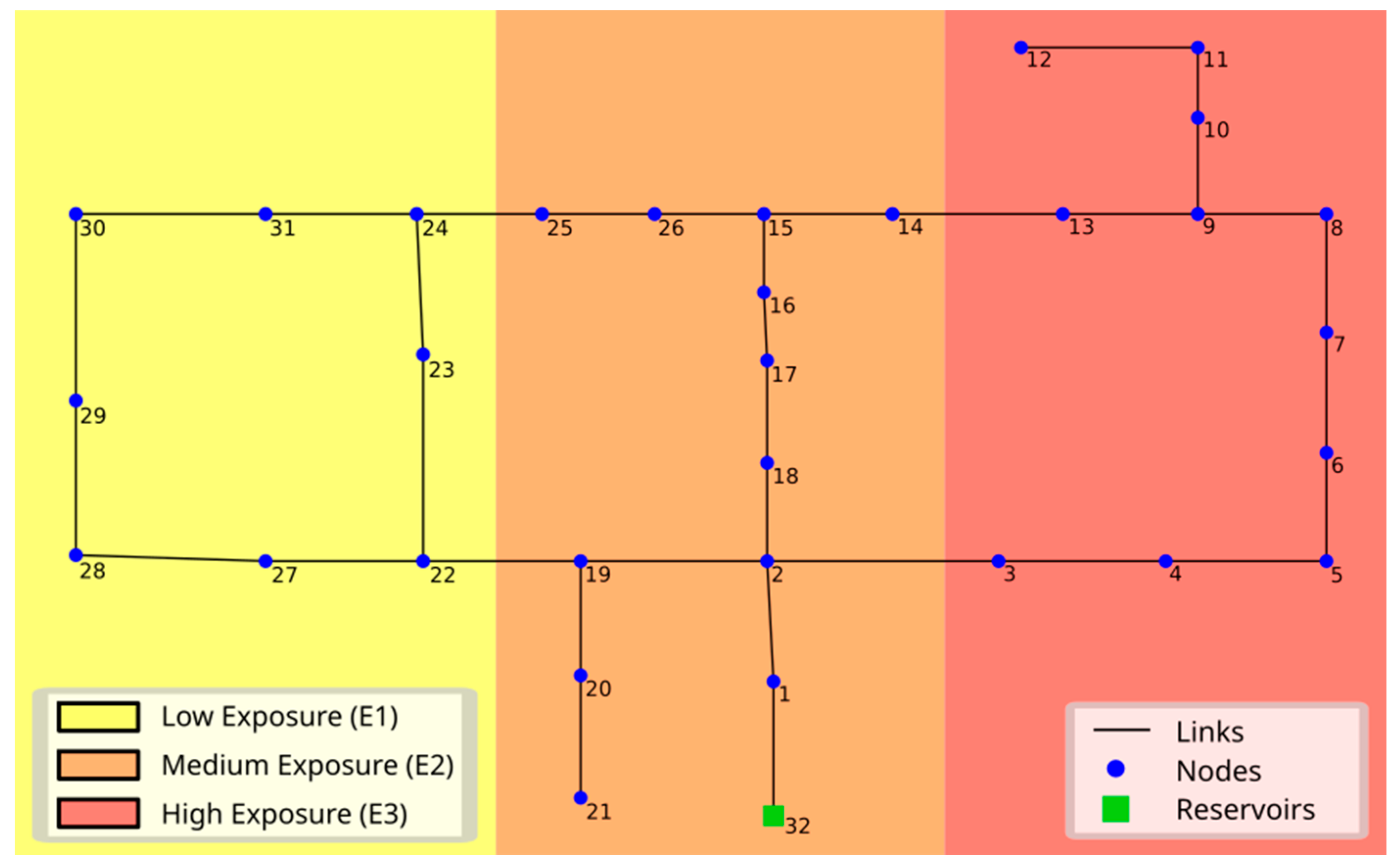
The first case study is the Hanoi WDN, often used in the literature to validate algorithms (see reference [67] for a description of the network). The network is characterized as follows (see Figure 4):
-
32 junction nodes;
-
34 pipes (links);
-
1 inlet point (reservoir);
-
pipe diameters from 304.8 to 1016 mm.
For demonstration purposes, it is assumed that the nodes 1, 10, 11, 12, 20, 21, and 32, are not origins of leakage. The value used for the emitter coefficient is EC = 0.1 L/(s·m0.5). The risk zoning based on exposure to Hydrogeological Disruption due to Leakage (HDL) is totally idealized (as we have no information about the WDN position and the exposure of the surrounding territory) and is simply used to test the proposed risk-based optimal sensor placement (OSP) methodology. Therefore, a fictitious zoning of the surrounding area with three exposure classes, ranging from the lowest E1 to the highest E3, is created (see Figure 4). A weight is assigned to each exposure class, which is inherited by the WDN junction nodes falling in it. Using the exposure values (E1, E2, E3) = (1, 3, 5), the corresponding risk classes (R1, R2, R3) = (1, 3, 5) are obtained (see Section 2.1).
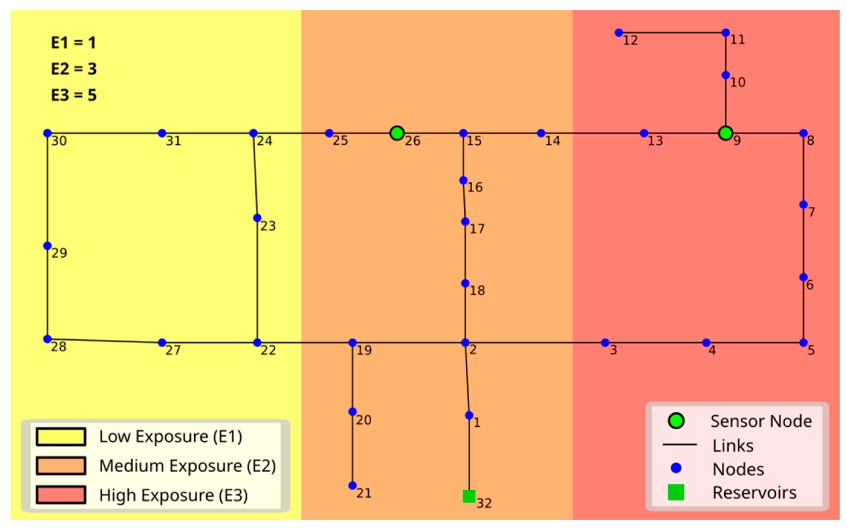
With these risk classes, the procedure of Section 2 is applied using NS = 2 sensors and the GA parameters of Table 1, under the assumption that the number of clusters equals the number of junction nodes where a leakage can be originated (NC = NN). The corresponding results are reported in Table 2 (second column), while the position of the sensors of the optimal set are represented in Figure 5 with green dots.
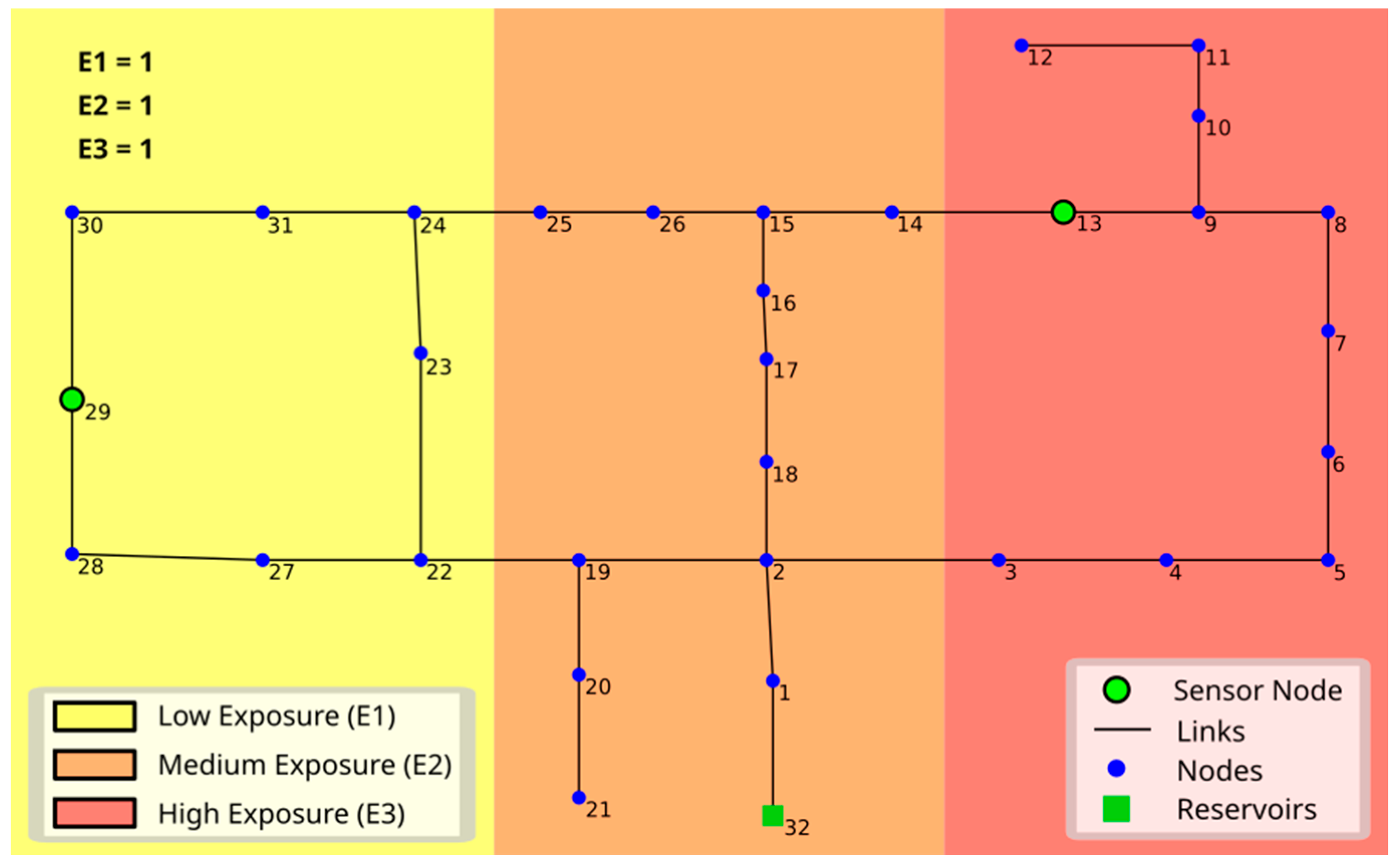
The exercise is repeated with homogeneous exposure parameters (E1, E2, E3) = (1, 1, 1), corresponding to the risk classes (R1, R2, R3) = (1, 1, 1). This condition corresponds to the case that no risk zoning is made, implying that the objective is the simple maximization of the localization likelihood aiming at the reduction of the water resource depletion, without regard to the leakage origin. The results of the optimization procedure are reported in Table 2 (third column), while the position of the sensors of the optimal set are represented in Figure 6 with green dots.
The comparison between Figure 5 and Figure 6 shows that the optimal sensor position for the case of inhomogeneous risk (Figure 5) is different from that of homogeneous risk (Figure 6). In the latter case, the sensors are evenly distributed through the WDN, while their positions concentrate in the higher-risk areas in the former case. The inspection of Table 2 shows that the localization accuracy in the higher-risk areas increases for the inhomogeneous risk case of Figure 5, while the average localization accuracy is slightly reduced with respect to the homogeneous risk case (Figure 6).
The results demonstrate the ability of the proposed methodology to deploy the sensors in configurations that lead to increased leak localization accuracy in higher risk areas.

3.2. Real Network 1

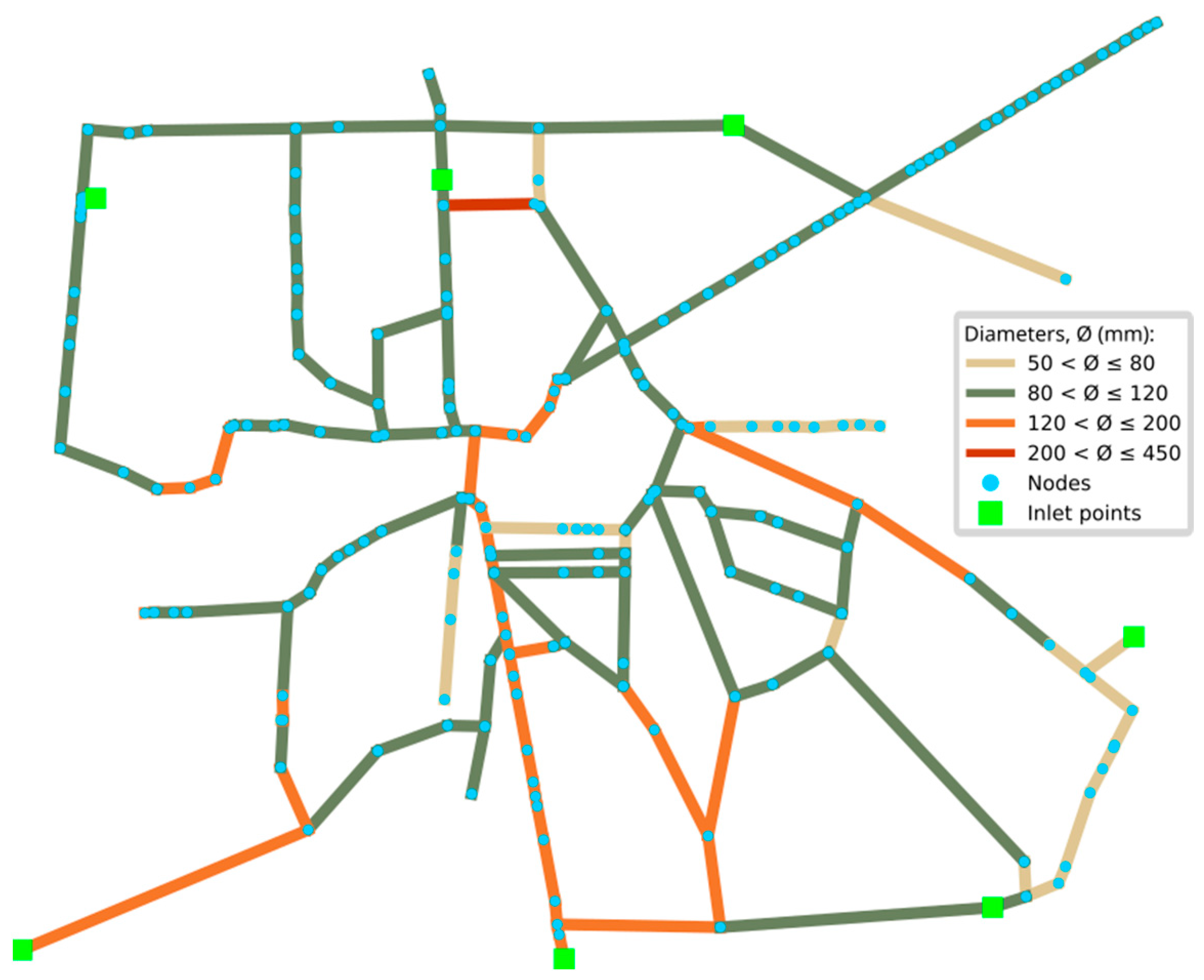
The second case study consists of a real-world WDN, here called Real Network 1, consisting of a medium-sized municipality in Southern Italy. The municipality covers a surface of nearly 5 km2 and consists of approximately 35,000 inhabitants, with an average population density of about 6600 inhabitants per km2. The town is located on a structural depression dominated by alluvial and marine deposits, pyroclastics and pyroclastic surge deposits derived from ignimbrites and tuffs or ignimbrite and tuff-forming eruptions. The altitude of the territory ranges between 101 and 146 m above sea level. The climate is Mediterranean, significantly influenced by tropical conditions. Summers are long and hot, while winters are short, relatively mild, with intense precipitation from October to February. The water utility of the considered municipality delivers drinking water to consumers through a network of pipes with a total length of nearly 23 km, 74.9% of which is made of cast iron, 17.3% of gray cast iron, 4.3% of iron, 2.8% of steel, and 0.7% of polyethylene. The main features of Real Network 1 (see Figure 7) are as follows:
-
206 junctions;
-
231 links;
-
7 inlet points with almost constant piezometric head;
-
pipe diameters from 53.6 to 406.4 mm.
The inspection of Figure 7 shows that Real Network 1 is characterized by a certain degree of central topological symmetry, with loops evenly developing around the city center. To derive a reasonable value of the emitter coefficient EC in Equation (3), it is assumed in this case study that the leakage discharge equals 1% of the total discharge entering the network [40].

3.2.1. Risk Zoning Based on Exposure to HDL

The evaluation of the network exposure component (Section 2.1) is carried out as follows:
(1)
The census information (available at https://www.istat.it/, accessed on 15 January 2024) is used to evaluate the distribution of the population density through the municipality.
(2)
Information levels on structures and infrastructure at the municipality scale are collected (from https://www.istat.it/, accessed on 15 January 2024).
(3)
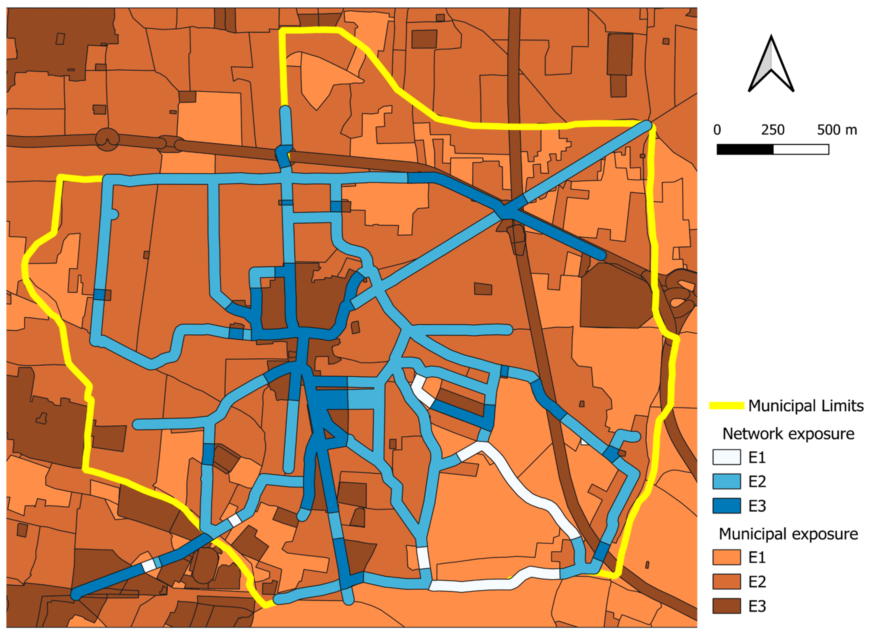
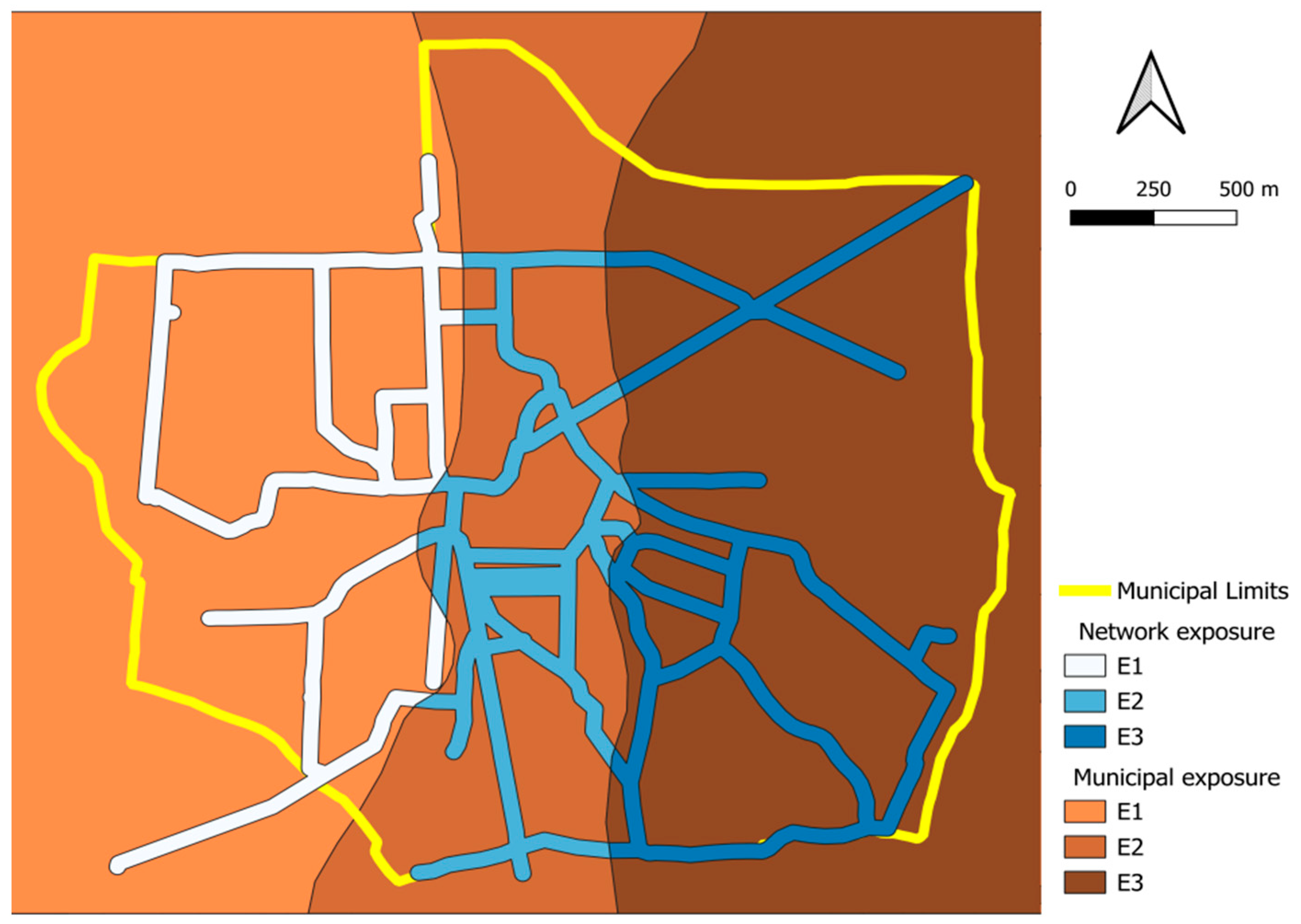
Three municipality exposure classes are introduced as follows (see the brown areas in Figure 8):
(a)
class E1 groups areas with low population density, where strategic infrastructures are absent, and areas with agricultural land uses;
(b)
class E2 represents areas with medium population density and buildings, mostly residential, with modest public or strategic functions;
(c)
class E3 applies to areas with significant population density, or areas with infrastructure, industries and buildings that have important public or strategic functions.
(4)
A buffer area whose width is W = 25 m is constructed along the WDN pipe. The buffer area individuates the municipality elements that can be potentially impacted by HDL because they are adjacent to the WDN pipes. The exposure class of the municipality elements is attributed also to homogeneous buffer sections (white and blue areas in Figure 8).
(5)
The exposure class of the buffer section is inherited by WDN junction nodes falling in it.
Based on the procedure above, the WDN zoning of Figure 8 is obtained. We observe that, like the topological characteristics of the WDN, the network zoning exhibits a certain degree of symmetry, where greater exposure E3 is attributed to the central part of the network, while a quite homogeneous exposure E2 is attributed around the centre.
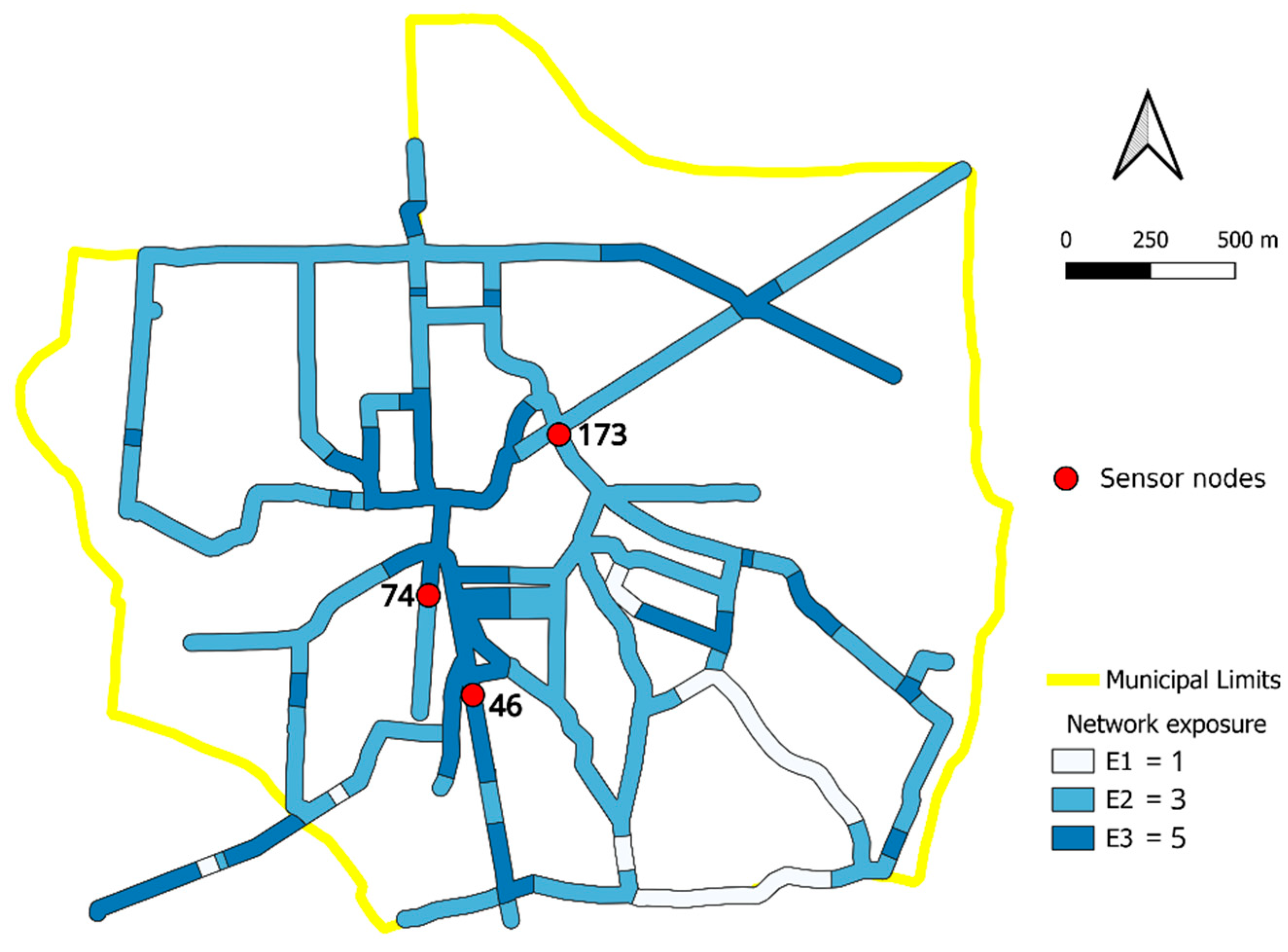
Using the exposure values (E1, E2, E3) = (1, 3, 5), the corresponding risk classes (R1, R2, R3) = (1, 3, 5) are obtained under the assumptions H = 1 and V = 1 (see Section 2.1). With these risk classes, the procedure of Section 2 is applied to Real Network 1 using NS = 3 sensors and the GA parameters of Table 1, under the assumption that the number of clusters equals the number of junction nodes (NC = NN). The corresponding results are reported in Table 3 (second column), while the position of the sensors of the optimal set are represented in Figure 9 with red dots.
The inspection of Table 3 shows that the accuracy of leakage localization from the generic node of the WDN (average localization accuracy) is equal to 0.740. If the focus is on the localization accuracy on the zones with higher exposition (E3), the localization accuracy increases to 0.837. The comparison confirms that the procedure is effective in biasing the sensor positions towards a configuration where the likelihood to localize leakages originated in zones with higher risk is increased. The inspection of Figure 9 shows that the sensor positions of the optimal set are close to the central part of the WDN, where the exposition is higher.
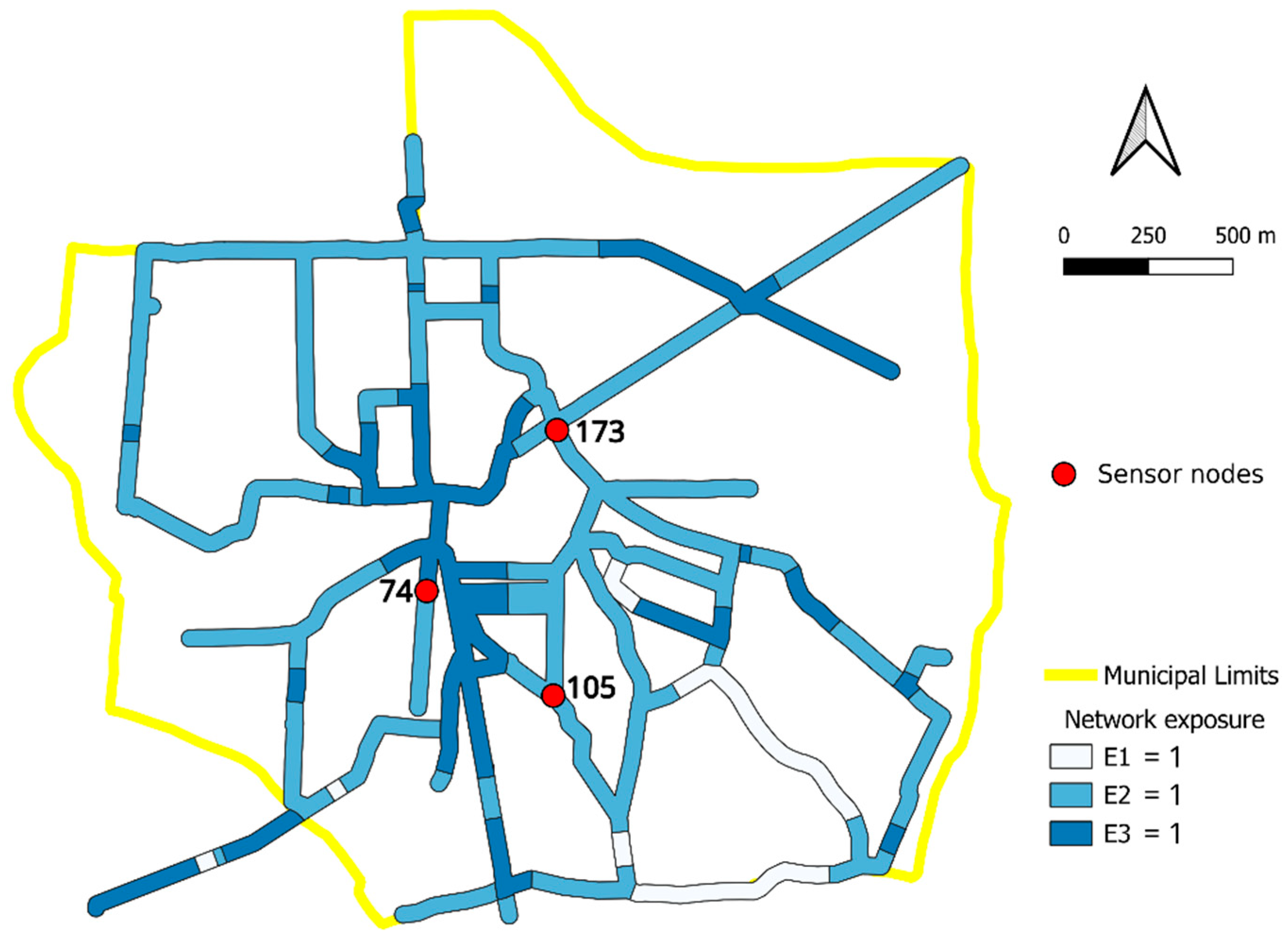
The exercise is repeated with fictious exposure parameters (E1, E2, E3) = (1, 1, 1), corresponding to the risk classes (R1, R2, R3) = (1, 1, 1). This condition corresponds to the case that no risk zoning is made, implying that the objective is the simple maximization of the localization likelihood aiming at the reduction of the water resource depletion, without regard to the leakage origin. The results of the optimization procedure are resumed in Table 3 (third column), while the sensor positions of the optimal set are represented in Figure 10.
The comparison between the second and third column of Table 3 shows that the average localization accuracy slightly increases from 0.740 to 0.743 in the homogeneous risk case, as expected. Nonetheless, the increase is very small, implying that, for the example of Real Network 1 with NS = 3 sensors, the optimal positioning of the leakage localization sensors aiming at the reduction of the risk from HDL (Figure 9) does not significantly affects the objective of localizing the generic leakage without reference to the risk (Figure 10).
With reference to the homogeneous risk case, the localization accuracy in the central part of the network, where E3 is predominant, only slightly decreases from 0.837 to 0.829 (third column of Table 3). Again, the optimal sensor positions cluster around the central part of the network, showing that the topological symmetry of Real Network 1 plays a role in constraining the sensor positions.

3.2.2. Fictious Risk Zoning

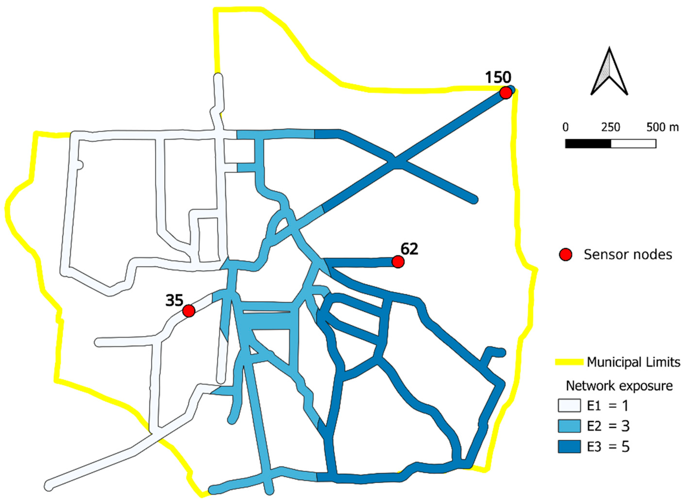
To better characterize the proposed method, an ad hoc fictitious exposure zoning is represented in Figure 11. Contrary to Figure 8, Figure 11 is characterized by strong asymmetry of the exposure distribution, with high exposure areas in the eastern part of the settlement and low exposure areas to the west. In this case also, the exposure values (E1, E2, E3) = (1, 3, 5), corresponding to risk classes (R1, R2, R3) = (1, 3, 5) and NS = 3 sensors, are used. The results of the optimization procedure are resumed in Table 4 (second column), while the sensor positions of the optimal set are represented in Figure 12.
The comparison between Table 3 and Table 4 shows that a strong asymmetry of the exposure distribution influences the average localization accuracy throughout the water distribution network, as expected. Nonetheless, the accuracy reduction is very mild (0.735), confirming that the objective of reducing the risk from HDL has no negative influence on the objective of increasing WDN sustainability by reducing the water resource depletion.
Interestingly, the comparison between Figure 9 and Figure 12 shows that the strong asymmetry of the exposure contributes to break the symmetry of the optimal sensor set positions. Indeed, two of the tree sensors (nodes 62 and 150 in Figure 8) are now in the zone with higher exposure (E3), while the last sensor (node 35) falls in the area with lower exposure (E1). This implies that the disposition of the sensors to the east and to the west of the urban area is sufficient to monitor the leakages originating also from the zone with middle exposure E2 in the central part of the network.

4. Conclusions

Global estimates of water losses from water distribution networks, mainly caused by faulty joints and damaged or deteriorated pipelines, are incompatible with sustainable development goals, and have major environmental, economic, and social implications. Leakages can cause not only water resource depletion but also the formation of cavities in the urban soil that can subsequently collapse (sinkholes), with possible victims and infrastructure destruction.
Leak detection and localization in water pipelines is an expanding research field and industry, driven by the critical need to save a precious resource and mitigate the consequences of leaks. Early leak detection can prevent significant water losses, soil infiltration leading to sinkholes, minimize infrastructure damage, protect the surrounding environment and people, and reduce costs. However, implementing a monitoring system across the water distribution network of an entire city can be expensive and complex. Therefore, it is crucial to first identify the areas with a higher risk of sinkholes and ground subsidence due to water leaks. Monitoring high-risk areas can optimize resource allocation by water network companies, thereby saving time, energy, and costs.
In this paper, we have proposed a novel framework for the optimal positioning of pressure sensors aiming at reducing the risk of hydrogeological disruption due to leakages from water distribution networks. The methodology is based on the use of a Genetic algorithm for the optimal positioning of the sensors and a Machine learning model for their training and evaluation.
The results show that:
-
the proposed risk-based methodology that accounts for the adverse impact due to hydrogeological disruption from undetected leaks is advantageous over conventional non-risk-based methods (that treat all elements at risk equally), since it prioritizes monitoring locations where more people and critical infrastructure could be potentially affected in the event of a leak, increasing the likelihood of leakage localization in higher risk zones due to sinkhole formation;
-
the ability of the proposed methodology to detect generic leakage is not adversely affected, facilitating the additional goal of reducing water resource depletion.
The model developed in this study can assist urban water management authorities in predicting the urban areas that require urgent monitoring against adverse impacts caused by leakages from underground pipelines, representing a valuable tool to strategically deploy the sensors in the network, meeting hydraulic, socio-economic, environmental and safety requirements.
Future research will focus on the broader utilization of real-world data at various stages of the presented process. Efforts will be made to implement the proposed framework using actual sensor pressure and flow data. Additionally, the different components of risk will be assessed in a more comprehensive and detailed manner. Furthermore, class weights will be analyzed and evaluated extensively to achieve more accurate characterizations tailored to the specific case of interest.

Author Contributions

Conceptualization, G.M., G.V. and L.C.; methodology, G.M., G.V. and L.C.; software, G.M.; validation, G.M.; formal analysis, G.M., G.V. and L.C.; investigation, G.M.; resources, G.M. and L.C.; data curation, G.M. and L.C.; writing—original draft preparation, G.M., G.V., Ç.A.İ. and L.C.; writing—review and editing, G.M., G.V., Ç.A.İ., L.C. and R.D.M.; visualization, G.M.; supervision, L.C. and R.D.M. All authors have read and agreed to the published version of the manuscript.

Funding

This research received no external funding.

Data Availability Statement

The data used for evaluating the network exposure (census data, information levels on structures and infrastructure at the municipality scale) are from publicly sourced databases available at https://www.istat.it/, accessed on 15 January 2024. The Version 2.2 of the open-source hydraulic simulation software EPANET is preserved at https://www.epa.gov/water-research/epanet, accessed on 9 October 2023, available via public access conditions. The library Toolkit Python EPANET (EPyT) is available at https://pypi.org/project/epyt/, accessed on 15 January 2024. Due to WDN security reasons, the data concerning the real-world WDN used in this study are available in anonymized and non-georeferenced form on reasonable request.

Acknowledgments

The writers want to acknowledge the three anonymous reviewers who contributed to improving the original version of the paper with their constructive comments.

Conflicts of Interest

The authors declare no conflicts of interest.

Nomenclature

CVcoefficient of variation
DC(t)demand pattern coefficient at time t
DTDecision Tree
EExposure
ECiemitter coefficient of the i-th node
GAGenetic Algorithm
GISGeographic information systems
HHazard
HDLHydrogeological Disruption due to Leakage
hipiezometric head at the i-th node
hst,istandardized value of hi
ISTATItalian National Institute of Statistics
Mk(P)localization accuracy of the set of sensors P referred to the leakages from the cluster Ωk
MLMachine Learning
Mp(P)fitness of the set of senors P
NAk(P)number of accurate predictions made by the set of sensors P regarding the leakages from the nodes of Ωk
NCnumber of localization clusters
Nknumber of leakage scenarios from the nodes of Ωk
NNnumber of junction nodes in the WDN
NRnumber of risk levels
NSnumber of pressure sensors
OSPOptimal sensor placement
Pset of NS pressure sensors
PCAPrincipal component analysis
Qiflow rate through the emitter at the i-th node
qBibase demand at the i-th node
qi(t)demand at the i-th node at time t
RRisk
Tsimulation time
ttime
USDUnited States dollar
Wbuffer area width
WDNwater distribution network
VVulnerability
σ h i standard deviation of hi
ΩkSubset (localization cluster) of Ω
μ h i mean of hi
µDC(t)Average demand coefficient at time t
Subscripts
iSubscript for nodes
kSubscript for the generic localization cluster

Appendix A

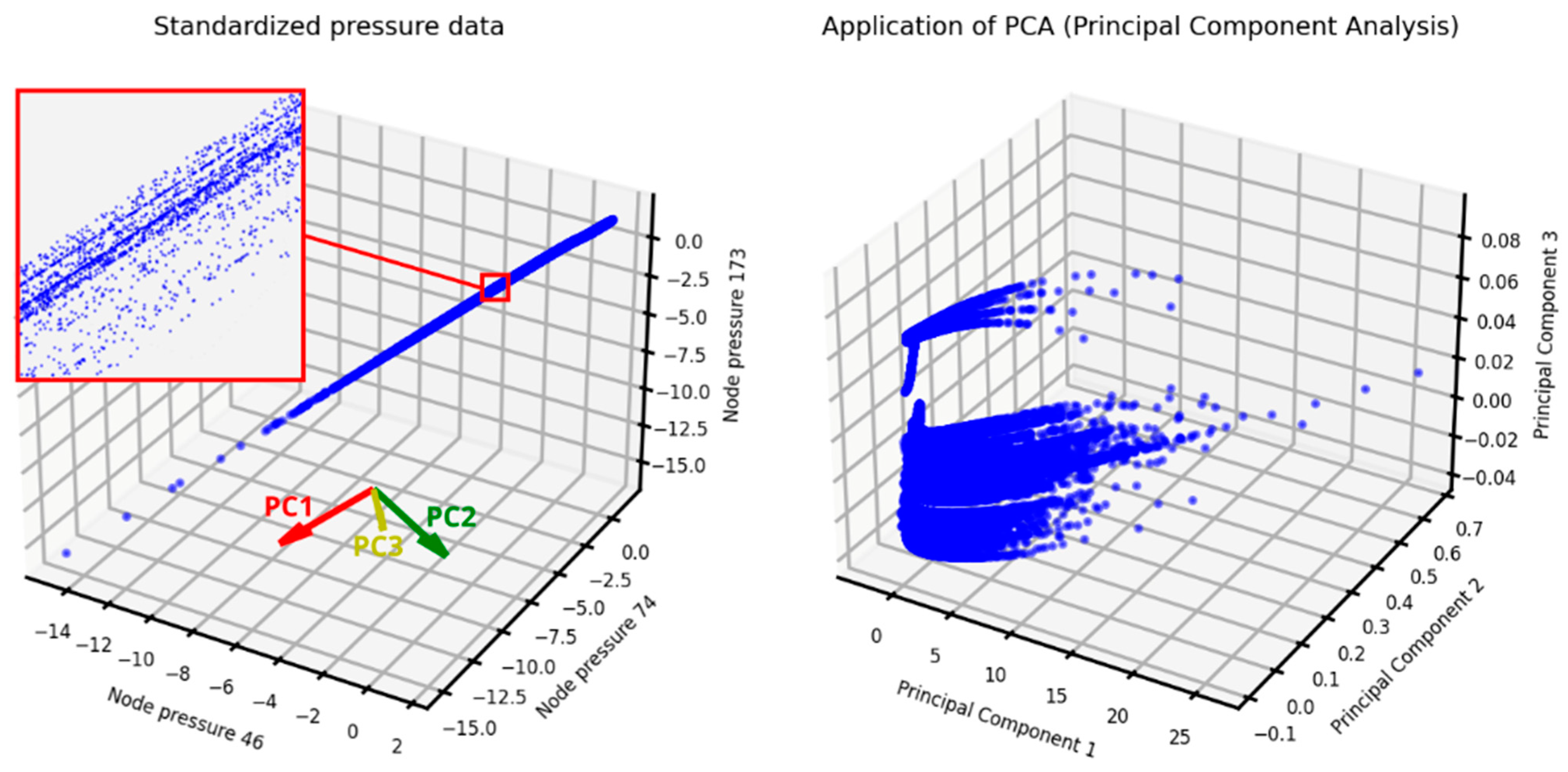
Figure A1 illustrates the transformation of standardized pressure data through the application of Principal Component Analysis (PCA). PCA enabled the emergence of the hidden structure within the dataset while simultaneously filtering out noise. Principal Component 1 (PC1) is prominently identifiable as the direction along which the data exhibit the most arrangement and dispersion, representing the maximum variance. In contrast, Principal Component 2 (PC2) and Principal Component 3 (PC3) exhibit significantly lower variance, as evidenced by the axis intervals in the PCA graph of Figure A1, right panel. To preserve a substantial amount of the original data’s variance, all principal components were retained, maintaining the original three dimensions corresponding to the number of sensors, even after PCA application.
Figure A1. Transformation of standardized pressure data by applying Principal Component Analysis (PCA): standardized pressure data with the identification of the PCA components (left panel), and transformed data (right panel).
Sustainability 16 05246 g0a1

References

  1. Gosling, S.N.; Arnell, N.W. A global assessment of the impact of climate change on water scarcity. Clim. Chang. 2016, 134, 371–385. [Google Scholar] [CrossRef]
  2. Fan, X.; Wang, X.; Zhang, X.; Yu, X. Machine learning based water pipe failure prediction: The effects of engineering, geology, climate and socio-economic factors. Reliab. Eng. Syst. Saf. 2022, 219, 108185. [Google Scholar] [CrossRef]
  3. Zaman, D.; Gupta, A.K.; Uddameri, V.; Tiwari, M.K.; Ghosal, P.S. Hydraulic performance benchmarking for effective management of water distribution networks: An innovative composite index-based approach. J. Environ. Manag. 2021, 299, 113603. [Google Scholar] [CrossRef] [PubMed]
  4. Robles-Velasco, A.; Cortés, P.; Muñuzuri, J.; De Baets, B. Prediction of pipe failures in water supply networks for longer time periods through multi-label classification. Expert. Syst. Appl. 2023, 213 Pt B, 119050. [Google Scholar] [CrossRef]
  5. Covelli, C.; Cozzolino, L.; Cimorelli, L.; Della Morte, R.; Pianese, D. Optimal location and setting of PRVs in WDS for leakage minimization. Water Resour. Manag. 2016, 30, 1803–1817. [Google Scholar] [CrossRef]
  6. Dastpak, P.; Sousa, R.L.; Dias, D. Soil Erosion Due to Defective Pipes: A Hidden Hazard Beneath Our Feet. Sustainability 2023, 15, 8931. [Google Scholar] [CrossRef]
  7. Alzarooni, E.; Ali, T.; Atabay, S.; Yilmaz, A.G.; Mortula, M.M.; Fattah, K.P.; Khan, Z. GIS-Based Identification of Locations in Water Distribution Networks Vulnerable to Leakage. Appl. Sci. 2023, 13, 4692. [Google Scholar] [CrossRef]
  8. Liemberger, R.; Wyatt, A. Quantifying the Global Non-Revenue Water Problem. Water Supply 2019, 19, 831–837. [Google Scholar] [CrossRef]
  9. ISTAT. Le Statistiche dell’ISTAT Sull’acqua—Anni 2020–2022. Report. 2023. Available online: https://www.istat.it/it/files//2023/03/GMA-21marzo2023.pdf (accessed on 19 April 2024). (In Italian).
  10. Karim, M.R.; Abbaszadegan, M.; LeChevallier, M. Potential for pathogen intrusion during pressure transients. J. Am. Water Work. 2003, 95, 134–146. [Google Scholar] [CrossRef]
  11. Ali, H.; Choi, J.-h. A Review of Underground Pipeline Leakage and Sinkhole Monitoring Methods Based on Wireless Sensor Networking. Sustainability 2019, 11, 4007. [Google Scholar] [CrossRef]
  12. Tharp, T.M. Mechanics of upward propagation of cover-collapse sinkholes. Eng. Geol. 1999, 52, 23–33. [Google Scholar] [CrossRef]
  13. Nisio, S.; Caramanna, G.; Ciotoli, G. Sinkholes in Italy: First results on the inventory and analysis. Geol. Soc. Lond. Spec. Publ. 2007, 279, 23–45. [Google Scholar] [CrossRef]
  14. Guo, S.; Shao, Y.; Zhang, T.; Zhu, D.Z.; Zhang, Y. Physical modeling on sand erosion around defective sewer pipes under the influence of groundwater. J. Hydraul. Eng. 2013, 139, 1247–1257. [Google Scholar] [CrossRef]
  15. Rodriguez-Espinosa, P.F.; Ochoa-Guerrero, K.M.; Milan-Valdes, S.; Teran-Cuevas, A.R.; Hernandez-Silva, M.G.; San Miguel-Gutierrez, J.C.; Caracheo-Gonzalez, J.J.; Creuheras Diaz, S. Impacts on groundwater-related anthropogenic activities on the development of sinkhole hazards: A case study from Central Mexico. Environ. Earth Sci. 2023, 82, 358. [Google Scholar] [CrossRef]
  16. Lee, E.J.; Shin, S.Y.; Ko, B.C.; Chang, C. Early sinkhole detection using a drone-based thermal camera and image processing. Infrared Phys. Technol. 2016, 78, 223–232. [Google Scholar] [CrossRef]
  17. Guarino, P.M.; Santo, A.; Forte, G.; De Falco, M.; Niceforo, D.M.A. Analysis of a database for anthropogenic sinkhole triggering and zonation in the Naples hinterland (Southern Italy). Nat. Hazards 2018, 91, 173–192. [Google Scholar] [CrossRef]
  18. Tufano, R.; Guerriero, L.; Annibali Corona, M.; Bausilio, G.; Di Martire, D.; Nisio, S.; Calcaterra, D. Anthropogenic sinkholes of the city of Naples, Italy: An update. Nat. Hazards 2022, 112, 2577–2608. [Google Scholar] [CrossRef]
  19. Sahu, P.; Lokhande, R.D. An Investigation of Sinkhole Subsidence and its Preventive Measures in Underground Coal Mining. Procedia Earth Planet. Sci. 2015, 11, 63–75. [Google Scholar] [CrossRef]
  20. Zou, Q.; Chen, Z.; Cheng, Z.; Liang, Y.; Xu, W.; Wen, P.; Zhang, B.; Liu, H.; Kong, F. Evaluation and intelligent deployment of coal and coalbed methane coupling coordinated exploitation based on Bayesian network and cuckoo search. Int. J. Min. Sci. Technol. 2022, 32, 1315–1328. [Google Scholar] [CrossRef]
  21. Zhang, D.-M.; Du, W.-W.; Peng, M.-Z.; Feng, S.-J.; Li, Z.-L. Experimental and numerical study of internal erosion around submerged defective pipe. Tunn. Undergr. Space Technol. 2020, 97, 103256. [Google Scholar] [CrossRef]
  22. Tan, Y.; Long, Y.Y. Review of cave-in failures of urban roadways in China: A database. J. Perform. Constr. Facil. 2021, 35, 04021080. [Google Scholar] [CrossRef]
  23. Indiketiya, S.; Jegatheesan, P.; Rajeev, P.; Kuwano, R. The influence of pipe embedment material on sinkhole formation due to erosion around defective sewers. Transp. Geotech. 2019, 19, 110–125. [Google Scholar] [CrossRef]
  24. Tan, F.; Tan, W.; Yan, F.; Qi, X.; Li, Q.; Hong, Z. Model Test Analysis of Subsurface Cavity and Ground Collapse Due to Broken Pipe Leakage. Appl. Sci. 2022, 12, 13017. [Google Scholar] [CrossRef]
  25. Guarino, P.M.; Nisio, S. Anthropogenic sinkholes in the territory of the city of Naples (Southern Italy). Phys. Chem. Earth Parts A/B/C 2012, 49, 92–102. [Google Scholar] [CrossRef]
  26. Kim, K.; Kim, J.; Kwak, T.Y.; Chung, C.K. Logistic regression model for sinkhole susceptibility due to damaged sewer pipes. Nat. Hazards 2018, 93, 765–785. [Google Scholar] [CrossRef]
  27. Casillas, M.; Puig, V.; Garza-Castañón, L.; Rosich, A. Optimal Sensor Placement for Leak Location in Water Distribution Networks Using Genetic Algorithms. Sensors 2013, 13, 14984–14985. [Google Scholar] [CrossRef]
  28. Steffelbauer, D.B.; Fuchs-Hanusch, D. Efficient Sensor Placement for Leak Localization Considering Uncertainties. Water Resour. Manag. 2016, 30, 5517–5533. [Google Scholar] [CrossRef]
  29. Cugueró-Escofet, M.À.; Puig, V.; Quevedo, J. Optimal Pressure Sensor Placement and Assessment for Leak Location Using a Relaxed Isolation Index: Application to the Barcelona Water Network. Control Eng. Pract. 2017, 63, 1–12. [Google Scholar] [CrossRef]
  30. Forconi, E.; Kapelan, Z.; Ferrante, M.; Mahmoud, H.; Capponi, C. Risk-based sensor placement methods for burst/leak detection in water distribution systems. Water Supply 2017, 17, 1663–1672. [Google Scholar] [CrossRef]
  31. Li, J.; Wang, C.; Qian, Z.; Lu, C. Optimal Sensor Placement for Leak Localization in Water Distribution Networks Based on a Novel Semi-Supervised Strategy. J. Process Control 2019, 82, 13–21. [Google Scholar] [CrossRef]
  32. Hu, Z.; Chen, W.; Chen, B.; Tan, D.; Zhang, Y.; Shen, D. Robust Hierarchical Sensor Optimization Placement Method for Leak Detection in Water Distribution System. Water Resour. Manag. 2021, 35, 3995–4008. [Google Scholar] [CrossRef]
  33. Hu, Z.; Chen, W.; Tan, D.; Chen, B.; Shen, D. Multi-Objective and Risk-Based Optimal Sensor Placement for Leak Detection in a Water Distribution System. Environ. Technol. Innov. 2022, 28, 102565. [Google Scholar] [CrossRef]
  34. Cheng, M.; Li, J. Optimal Sensor Placement for Leak Location in Water Distribution Networks: A Feature Selection Method Combined with Graph Signal Processing. Water Res. 2023, 242, 120313. [Google Scholar] [CrossRef] [PubMed]
  35. Zeng, X.; Yu, Y.; Yang, S.; Lv, Y.; Sarker, M.N.I. Urban Resilience for Urban Sustainability: Concepts, Dimensions, and Perspectives. Sustainability 2022, 14, 2481. [Google Scholar] [CrossRef]
  36. United Nations. General Assembly Resolution A/RES/70/1. In Transforming Our World, the 2030 Agenda for Sustainable Development; United Nations: New York, NY, USA, 2015; Available online: https://sdgs.un.org/2030agenda (accessed on 15 January 2024).
  37. Gao, Y.; Alexander, E.C. Sinkhole hazard assessment in Minnesota using a decision tree model. Environ. Geol. 2008, 54, 945–956. [Google Scholar] [CrossRef]
  38. Taheri, K.; Shahabi, H.; Chapi, K.; Shirzadi, A.; Gutiérrez, F.; Khosravi, K. Sinkhole susceptibility mapping: A comparison between Bayes-based machine learning algorithms. Land. Degrad. Dev. 2019, 30, 730–745. [Google Scholar] [CrossRef]
  39. Bianchini, S.; Confuorto, P.; Intrieri, E.; Sbarra, P.; Di Martire, D.; Calcaterra, D.; Fanti, R. Machine learning for sinkhole risk mapping in Guidonia-Bagni di Tivoli plain (Rome), Italy. Geocarto Int. 2024, 37, 16687–16715. [Google Scholar] [CrossRef]
  40. Ali, H.; Choi, J.-h. Risk Prediction of Sinkhole Occurrence for Different Subsurface Soil Profiles due to Leakage from Underground Sewer and Water Pipelines. Sustainability 2020, 12, 310. [Google Scholar] [CrossRef]
  41. Karoui, T.; Jeong, S.-Y.; Jeong, Y.-H.; Kim, D.-S. Experimental Study of Ground Subsidence Mechanism Caused by Sewer Pipe Cracks. Appl. Sci. 2018, 8, 679. [Google Scholar] [CrossRef]
  42. Crichton, D. The Risk Triangle. In Natural Disaster Management; Ingleton, J., Ed.; Tudor Rose: London, UK, 1999; pp. 102–103. [Google Scholar]
  43. Intrieri, E.; Confuorto, P.; Bianchini, S.; Rivolta, C.; Leva, D.; Gregolon, S.; Buchignani, V.; Fanti, R. Sinkhole risk mapping and early warning: The case of Camaiore (Italy). Front. Earth Sci. 2023, 11, 1172727. [Google Scholar] [CrossRef]
  44. Rossman, L.; Woo, H.; Tryby, M.; Shang, F.; Janke, R.; Haxton, T. EPANET 2.2 User Manual; EPA/600/R-20/133; U.S. Environmental Protection Agency: Washington, DC, USA, 2020. [Google Scholar]
  45. Cozzolino, L.; Della Morte, R.; Palumbo, A.; Pianese, D. Stochastic approaches for sensors placement against intentional contaminations in water distribution systems. Civ. Eng. Environ. Syst. 2011, 28, 75–98. [Google Scholar] [CrossRef]
  46. Gupta, G. Monitoring Water Distribution Network Using Machine Learning. Master’s Thesis, KTH Royal Institute of Technology, Stockholm, Sweden, 2017. [Google Scholar]
  47. Ares-Milián, M.J.; Quiñones-Grueiro, M.; Verde, C.; Llanes-Santiago, O. A Leak Zone Location Approach in Water Distribution Networks Combining Data-Driven and Model-Based Methods. Water 2021, 13, 2924. [Google Scholar] [CrossRef]
  48. Alves, D.; Blesa, J.; Duviella, E.; Rajaoarisoa, L. Robust Data-Driven Leak Localization in Water Distribution Networks Using Pressure Measurements and Topological Information. Sensors 2021, 21, 7551. [Google Scholar] [CrossRef] [PubMed]
  49. Quiñones-Grueiro, M.; Bernal-de Lázaro, J.M.; Verde, C.; Prieto-Moreno, A.; Llanes-Santiago, O. Comparison of classifiers for leak location in water distribution networks. IFAC-Pap. Line 2018, 51, 407–413. [Google Scholar] [CrossRef]
  50. Mukunoki, T.; Kumano, N.; Otani, J.; Kuwano, R. Visualization of three dimensional failure in sand due to water inflow and soil drainage from defective underground pipe using X-ray CT. Soils Found. 2009, 49, 959–968. [Google Scholar] [CrossRef]
  51. El-Zahab, S.; Zayed, T. Leak detection in water distribution networks: An introductory overview. Smart Water 2019, 4, 5. [Google Scholar] [CrossRef]
  52. Jena, J.; Mahed, G.; Chabata, T.; Doucoure, M.; Gibbon, T. Monitoring and early warning detection of collapse and subsidence sinkholes using an optical fibre seismic sensor. Cogent Eng. 2024, 11, 2301152. [Google Scholar] [CrossRef]
  53. Maharana, K.; Mondal, S.; Nemade, B. A Review: Data Pre-Processing and Data Augmentation Techniques. Glob. Transit. Proc. 2022, 3, 91–99. [Google Scholar] [CrossRef]
  54. Kurita, T. Principal Component Analysis (PCA). In Computer Vision; Springer: Cham, Switzerland, 2020; pp. 1–4. [Google Scholar] [CrossRef]
  55. Tipping, M.E.; Bishop, C.M. Mixtures of Probabilistic Principal Component Analyzers. Neural Comput. 1999, 11, 443–482. [Google Scholar] [CrossRef]
  56. Halko, N.; Martinsson, P.G.; Tropp, J.A. Finding Structure with Randomness: Probabilistic Algorithms for Constructing Approximate Matrix Decompositions. SIAM Rev. 2011, 53, 217–288. [Google Scholar] [CrossRef]
  57. Martinsson, P.G.; Rokhlin, V.; Tygert, M. A Randomized Algorithm for the Decomposition of Matrices. Appl. Comput. Harmon. Anal. 2011, 30, 47–68. [Google Scholar] [CrossRef]
  58. Aydogdu, M.; Firat, M. Estimation of Failure Rate in Water Distribution Network Using Fuzzy Clustering and LS-SVM Methods. Water Resour. Manag. 2015, 29, 1575–1590. [Google Scholar] [CrossRef]
  59. Kang, J.; Park, Y.J.; Lee, J.; Wang, S.H.; Eom, D.S. Novel leakage detection by ensemble CNN-SVM and graph-based localization in water distribution systems. IEEE Trans. Ind. Electron. 2017, 65, 4279–4289. [Google Scholar] [CrossRef]
  60. Quiñones-Grueiro, M.; Ares Milián, M.; Sánchez Rivero, M.; Silva Neto, A.J.; Llanes-Santiago, O. Robust Leak Localization in Water Distribution Networks Using Computational Intelligence. Neurocomputing 2021, 438, 195–208. [Google Scholar] [CrossRef]
  61. Sousa, D.P.; Du, R.; Mairton Barros Da Silva, J., Jr.; Cavalcante, C.C.; Fischione, C. Leakage Detection in Water Distribution Networks Using Machine-Learning Strategies. Water Supply 2023, 23, 1115–1126. [Google Scholar] [CrossRef]
  62. Shen, Y.; Cheng, W. A Tree-Based Machine Learning Method for Pipeline Leakage Detection. Water 2022, 14, 2833. [Google Scholar] [CrossRef]
  63. Ayati, A.H.; Haghighi, A. Multiobjective Wrapper Sampling Design for Leak Detection of Pipe Networks Based on Machine Learning and Transient Methods. J. Water Resour. Plan. Manag. 2023, 149, 04022076. [Google Scholar] [CrossRef]
  64. Warad, A.A.M.; Wassif, K.; Darwish, N.R. An ensemble learning model for forecasting water-pipe leakage. Sci. Rep. 2024, 14, 10683. [Google Scholar] [CrossRef] [PubMed]
  65. Fan, X.; Zhang, X.; Yu, X. Machine Learning Model and Strategy for Fast and Accurate Detection of Leaks in Water Supply Network. J. Infrastruct. Preserv. Resil. 2021, 2, 10. [Google Scholar] [CrossRef]
  66. Alhijawi, B.; Awajan, A. Genetic algorithms: Theory, genetic operators, solutions, and applications. Evol. Intel. 2023, 17, 1245–1256. [Google Scholar] [CrossRef]
  67. Fujiwara, O.; Khang, D.B. A two-phase decomposition method for optimal design of looped water distribution networks. Water Res. Res. 1990, 26, 539–549. [Google Scholar] [CrossRef]
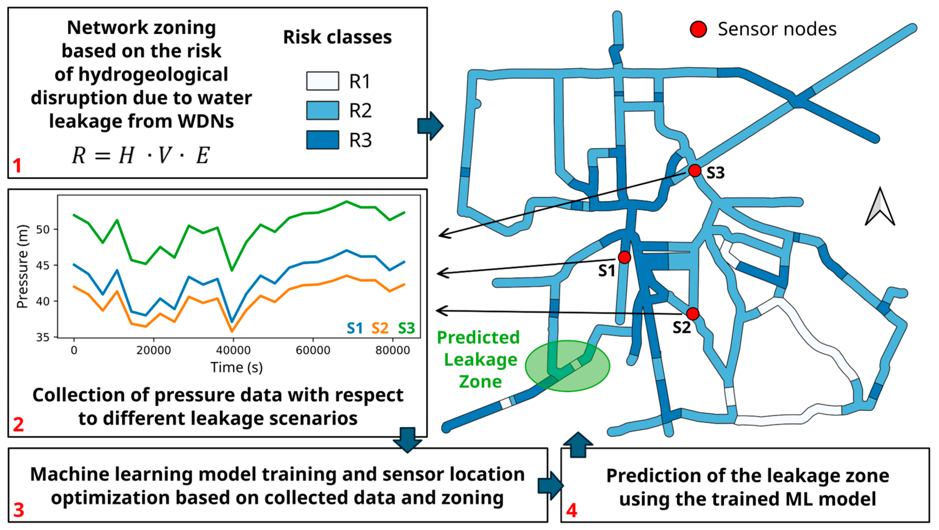
Figure 1. Summary representation of the employed methodology. R = risk, H = hazard, V = Vulnerability, E = exposure. Risk classes range from the lowest (R1) to the highest (R3).
Sustainability 16 05246 g001
Figure 2. Variability of µDC(t). The averaged value of µDC(t) is represented with a red broken line.
Sustainability 16 05246 g002
Figure 3. Flowchart of the GA process (left column), with the call to the fitness function evaluation of the right column (DT model). The asterisk symbol (*) in the left column indicates that the routine described in the right column must be executed.
Sustainability 16 05246 g003
Figure 4. Hanoi network. Fictitious zoning of the surrounding area with three exposure classes E1 (yellow), E2 (orange), E3 (red).
Sustainability 16 05246 g004
Figure 5. Hanoi network. Optimal position of NS = 2 sensors based on fictitious zoning with different exposure weights (E1 = 1, E2 = 3, E3 = 5).
Sustainability 16 05246 g005
Figure 6. Hanoi network. Optimal position of NS = 2 sensors based on fictitious zoning with homogeneous exposures (E1 = 1, E2 = 1, E3 = 1).
Sustainability 16 05246 g006
Figure 7. Layout of the real-world water distribution network, Real Network 1. The pipe diameter classes are denoted with different colors.
Sustainability 16 05246 g007
Figure 8. Real network 1. WDN zoning (white and blue areas) based on the municipality exposure to HDL (brown areas).
Sustainability 16 05246 g008
Figure 9. Real Network 1. Optimal position of NS = 3 sensors based on the municipality exposure to HDL with different exposures weights (E1, E2, E3) = (1, 3, 5).
Sustainability 16 05246 g009
Figure 10. Real Network 1. Optimal position of NS = 3 sensors based on the municipality exposure to HDL with homogeneous exposures weights (E1, E2, E3) = (1, 1, 1).
Sustainability 16 05246 g010
Figure 11. Real network 1. WDN zoning (white and blue areas) based on fictitious municipality exposure to HDL (brown areas).
Sustainability 16 05246 g011
Figure 12. Real Network 1. Optimal position of NS = 3 sensors based on fictitious exposures to HDL (Figure 11) with different exposures weights (E1, E2, E3) = (1, 3, 5).
Sustainability 16 05246 g012
Table 1. Genetic algorithm parameters.
GA ParameterDescription
CrossoverOne point
Crossover probability100%
Mutation probability5%
Population size 60
Number of generations500
Table 2. Hanoi network. Optimization results with fictitious risk zoning. Inhomogeneous exposure weights (E1, E2, E3) = (1, 3, 5) (second column) and homogeneous exposure weights (E1, E2, E3) = (1, 1, 1) (third column).
E1, E2, E31, 3, 51, 1, 1
Optimal sensor set9, 2613, 29
Average localization accuracy0.8900.896
Localization accuracy in E2–E30.896–0.8900.895–0.857
Table 3. Real Network 1. Optimization results with reference to risk zoning based on the municipality exposure to HDL (Figure 8) with different exposure weights (E1, E2, E3) = (1, 3, 5) (second column) and with homogeneous exposure weights (E1, E2, E3) = (1, 1, 1) (third column).
E1, E2, E31, 3, 51, 1, 1
Optimal sensor set46, 74, 17374, 105, 173
Average localization accuracy0.7400.743
Localization accuracy in E2–E30.700–0.8370.707–0.829
Table 4. Real Network 1. Optimization results with reference to risk zoning based on fictitious municipality exposure to HDL (Figure 11) with different exposure weights (E1, E2, E3) = (1, 3, 5).
E1, E2, E31, 3, 5
Optimal sensor positions35, 62, 150
Average localization accuracy0.735
Localization accuracy in E2–E30.723–0.867
Disclaimer/Publisher’s Note: The statements, opinions and data contained in all publications are solely those of the individual author(s) and contributor(s) and not of MDPI and/or the editor(s). MDPI and/or the editor(s) disclaim responsibility for any injury to people or property resulting from any ideas, methods, instructions or products referred to in the content.