Abstract
In order to address the problems of range ambiguity and azimuth ambiguity in the wide-swath imaging of synthetic aperture radar (SAR), this paper proposes a multi-beam SAR two-dimensional ambiguity suppression method based on azimuth phase coding (APC). The scheme employs an elevation simultaneous multi-beam transmission system with azimuth under-sampling, transmitting different APC waveforms to various range-ambiguous sub-regions. After receiving the echoes, the azimuth digital beamforming (DBF) is used to separate the APC waveform echoes with multi-order Doppler ambiguity, achieving azimuth reconstruction and range ambiguity suppression simultaneously. Finally, the elevation nulling DBF is used to further suppress range ambiguity and obtain the SAR wide-swath image. The superiority of this scheme is reflected in the following aspects: the azimuth DBF simultaneously suppresses azimuth and range ambiguity, the influence of height fluctuations on the ability to suppress range ambiguity is weakened, the use of elevation nulling DBF further enhances the level of range ambiguity suppression, and different range sub-regions can adopt different range resolutions and working modes. The feasibility of this scheme is verified through theoretical analysis and simulation.
1. Introduction
In the application of synthetic aperture radar (SAR), a larger swath width favors lessening the number of flights and ameliorating the efficiency of information acquisition [1]. Constrained by the minimum antenna size, traditional single-input single-output (SISO) SAR cannot simultaneously solve the problems of range ambiguity and Doppler ambiguity [2,3,4,5]. Single-input multiple-output (SIMO) SAR utilizes multiple receiving channels to obtain additional degrees of freedom (DOF), and the methods such as multiple azimuth beams and multiple elevation beams have been proposed to address issues of range ambiguity and azimuth ambiguity [6,7,8,9,10,11]. The azimuth multi-beam technology divides the whole synthetic aperture length into multiple azimuth sub-beams, abating the requirement for pulse repetition frequency (PRF) [6,7,8,9,10]. The elevation multi-beam method divides the range swath into multiple sub-regions, with each sub-beam pointing towards the incoming direction of echo from its corresponding sub-region, effectively suppressing range ambiguity [11].
Multiple-input multiple-output (MIMO) SAR incorporates transmission DOF into SIMO–SAR. By designing orthogonal waveforms and separating the corresponding echoes of transmission waveforms at the receiving end, equivalent transmission beamforming is achieved, greatly enhancing system DOF. This provides insights into high-resolution and wide-swath (HRWS) imaging, ground moving target indication (GMTI), and other applications [12,13,14,15]. The code-division orthogonal waveform echoes can be separated by matching filter [16,17]. However, the non-orthogonal energy between waveforms is dispersed rather than eliminated, making it unsuitable for range ambiguity suppression in huge scenes. The orthogonal frequency division multiplexing (OFDM) waveform proposed in [18,19] improves the echo separation effect. The literature [20,21] put forward a HRWS method for frequency diversity array (FDA) MIMO–SAR, introducing additional transmission DOF to achieve range ambiguity suppression in the spatial frequency domain. However, the above orthogonal waveform schemes have significant performance degradation in distributed scene imaging.
In order to solve the orthogonality problem of the same frequency waveforms, slow-time phase-coded waveforms were explored in references [22,23,24,25,26,27,28,29,30,31] and used for range ambiguity suppression [22,23,24,25,26,29,30,31]. Ref. [25] proposed the pulse phase coding (PPC) method, incorporating phases of and − into the transmitted pulses at different azimuth times. The echo from the ambiguous area will undergo a frequency shift in the Doppler domain, and using a Doppler domain filter can effectively suppress range ambiguity. However, this method can only result in a frequency shift of PRF/2 and cannot distinguish continuous order ambiguity. Ref. [26] combined the azimuth phase coding (APC) waveform with two orthogonal nonlinear frequency modulation waveforms to achieve the separation of continuous order ambiguity. However, it only discussed one APC waveform. In [27], a space time coding (STC) waveform was proposed. STC waveform echoes differ from Doppler shifts, and echoes of different STC waveforms can be separated through the band-pass filter in the Doppler domain. However, the requirement of PRF of several times the Doppler bandwidth severely limits the practical application of this method. Ref. [28] applied azimuth digital beamforming (DBF) technology to MIMO–SAR of APC waveforms, using azimuth DBF to separate echoes of different APC waveforms. In this scheme, the system PRF only needs to be slightly larger than the Doppler bandwidth. In [29], a MIMO–SAR extended APC scheme for suppressing range ambiguity was proposed, using azimuth DBF to separate APC waveform echoes and suppress clutters in different ambiguity areas. However, it excluded further reduction of system PRF. Ref. [30] put forward an improved reconstruction method based on a quadratic constraint optimization model for multi-channel SAR systems with non-uniform sampling in the azimuth direction of APC waveforms. Although this method achieves APC waveform echo reconstruction when the PRF is lower than the Doppler bandwidth, it merely discusses the range ambiguity suppression of a single APC waveform. The researchers in [31] constructed a method for reconstructing and separating APC waveform echoes with non-uniform sampling in azimuth. The separated APC waveform echoes can be used to realize multiple SAR modes or improve image signal-to-noise ratio (SNR). However, it only includes the reconstruction methods of two APC waveforms, and the Doppler ambiguity components of each order of various APC waveforms cannot be separated simultaneously.
With the increasing demand for wide-swath imaging in practical applications, when performing range ambiguity suppression, the maximum unambiguous range should be as large as possible. Therefore, in the presence of range ambiguity and Doppler ambiguity, designing new SAR systems to improve two-dimensional ambiguity suppression capability and achieve wide-swath non-ambiguity imaging of scenes is an urgent exploration direction.
This article investigates the two-dimensional ambiguity suppression problem in APC–MIMO–SAR. In the modeling phase, a simultaneous multi-beam transmission system in the elevation direction is adopted, a two-dimensional array receives echoes, and slow-time phase modulation is incorporated into each transmitting beam. In addition, azimuth DBF is performed on the received echoes with range ambiguity and azimuth ambiguity. At the same time, as each APC waveform echo is separated, the multi-order Doppler ambiguity components of each APC waveform echo are separated, and the APC waveform echoes are reconstructed. Moreover, demodulation and elevation nulling DBF are conducted on the reconstructed APC waveform echoes to further suppress range ambiguity. It needs to be clarified that the azimuth ambiguity and Doppler ambiguity in this article have the same meaning.
In the analysis phase, the feasibility of the proposed two-dimensional ambiguity suppression scheme was verified through the simulation of point-like targets and distributed targets.
The structure of this article is as follows: Section 2 designs a signal model for APC–MIMO–SAR. Section 3 introduces the simultaneous separation method for each APC waveform echo and each order Doppler ambiguity component, as well as the wide-swath imaging process under two-dimensional ambiguity. Section 4 presents the numerical experimental results. Finally, the conclusions are drawn in Section 5.
2. MIMO–SAR System Signal Model Based on APC Waveform
2.1. APC Waveform
This section takes four APC waveforms as examples to reveal the generation of APC waveforms and the Doppler orthogonality of their echoes. Then, the MIMO–SAR system used in this article is introduced. A linear array in the elevation direction simultaneously transmits multiple orthogonal waveforms, and the echoes are received by a two-dimensional array. Finally, the reasons for the range ambiguity and azimuth ambiguity of the system are theoretically analyzed, laying the foundation for the subsequent proposing of the two-dimensional ambiguity suppression scheme.
The APC waveform is a type of Doppler domain orthogonal linear frequency modulation (LFM) waveform that has been extensively used in MIMO–SAR. It adds a phase that varies linearly with azimuth slow time to the transmission signal, causing the corresponding echo to generate a fixed Doppler shift in the Doppler domain. The slope of the linear phase directly determines the magnitude of this Doppler shift. Therefore, the echoes of different APC waveforms can be separated in the Doppler domain.
In this article, multiple APC waveforms are transmitted to different range-ambiguous sub-regions. The expression for the APC waveform corresponding to the -th range sub-region is
where , representing the imaginary number symbol; represents a window function, which is equal to one for or zero if otherwise; is the number of sub-regions (waveforms); denotes the range sub-region index; represents the azimuth slow time; is the range fast time; stands for the PRF of SAR; represents the carrier frequency; denotes the duration of a LFM signal; and is the frequency modulation rate of the -th LFM signal. It is worth noting that the transmission waveforms corresponding to different range sub-regions can adopt different to achieve multiple range resolutions.
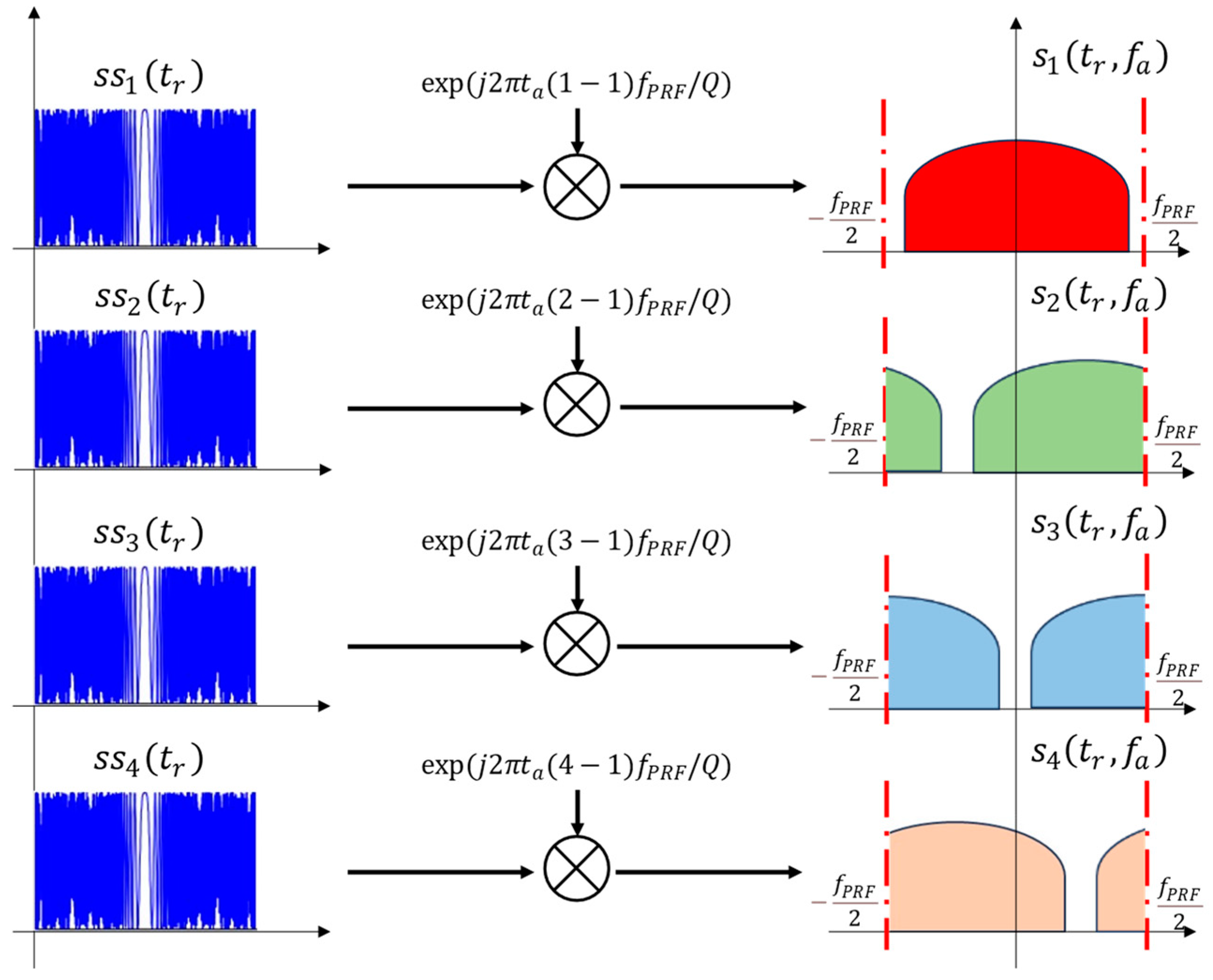
For the APC waveform of Equation (1), Figure 1 shows its corresponding generation method and its echo in the Doppler domain when , where denotes the Doppler frequency. It can be seen that the four APC waveform echoes have different performances in the Doppler domain. In this article, the transmission DBF technology is used to send APC waveforms to multiple range-ambiguous sub-regions for subsequent range ambiguity suppression.

Figure 1.
APC waveform generation.
2.2. MIMO–SAR System and the Principle of Two-Dimensional Ambiguity
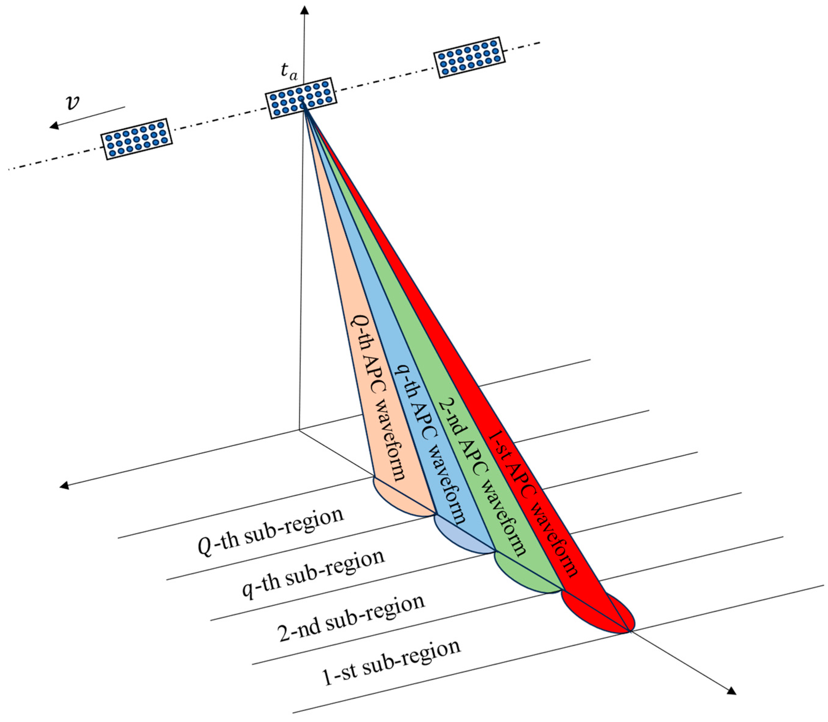
The MIMO–SAR system in this article adopts a two-dimensional array in the elevation and azimuth directions. The linear array in the elevation direction transmits signals, and the two-dimensional array receives echoes. The number of elements in the elevation direction is , and the spacing between them is ; the number of elements in the azimuth direction is , and the spacing between them is . As shown in Figure 2, SAR moves along the azimuth direction at a speed of and simultaneously transmits multiple beams using the linear array in the elevation direction at each azimuth moment. Each beam corresponds to an APC waveform and points toward a range-ambiguous sub-region.
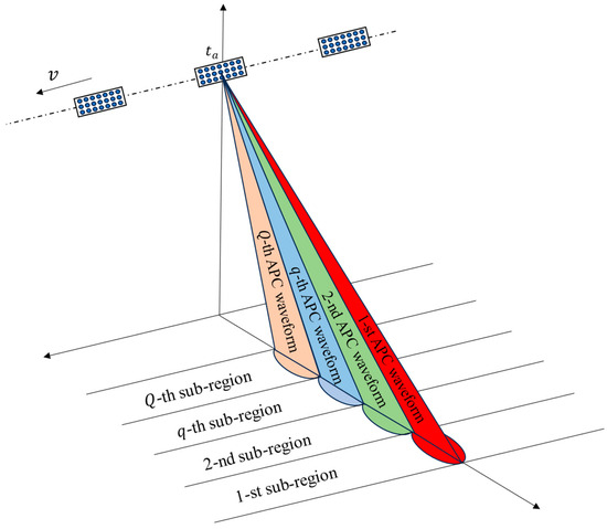
Figure 2.
The MIMO–SAR elevation multi-beam system.
According to Equation (1), the transmitted waveform of the -th element in the elevation direction toward the -th range sub-region can be expressed as
where ; denotes the angle between the center of the -th range sub-region and the normal direction of the elevation linear array; and represents the wavelength.
If the Doppler bandwidth of the SAR echo exceeds the designed PRF, direct imaging of the echo will lead to azimuth ambiguity in the SAR image due to azimuth under-sampling. This can be addressed by using azimuth multi-channel methods [6,7,8]. The maximum unambiguous range determined by the PRF of the SAR system can be expressed as
where represents the speed of light. As can be seen, a lower PRF will result in a larger unambiguous range. This article digs into the issue of range ambiguity suppression with insufficient PRF to achieve two-dimensional ambiguity suppression and further augment imaging swath.
Figure 3 presents the principle of range ambiguity of echoes in different range subregions of the proposed scheme. Specifically, in the absence of range ambiguity, echoes will be received in the current receiving window after transmitting signals. When the imaging area is far from the radar, the echoes will be received after several pulse repetition intervals (PRI). At this time, multiple echoes from different sub-regions are received in the same receiving window, resulting in range ambiguity. In this scheme, the APC waveform echoes of different range sub-regions are received in the same receiving window after different numbers of PRIs. The nearest range sub-region is numbered as , and the range ambiguity can be expressed as
where is the slant range between the -th range sub-region and radar, and represents the range ambiguity order of the -th range sub-region. The difference in range ambiguity orders between adjacent sub-regions is 1.
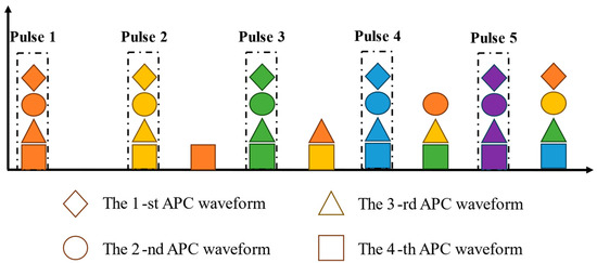
Figure 3.
The principle of range ambiguity of the proposed scheme.
Transmitted waveforms are received by the receiving elements after being reflected by the ground. Due to the coherent synthesis of the transmitted signals in space by transmitting DBF, there is no need to separately consider the echoes corresponding to each transmitting element. According to Equation (4), the range-ambiguous echo received by the -th azimuth element () in the -th elevation direction can be expressed as
where represents the amplitude of the target in the -th range sub-region. Echo delay refers to the two-way delay of the corresponding waveform transmitted to the ground and returned, which can be expressed as
where represents the direction of arrival (DOA) of echo in the azimuth direction; represents the DOA of echo in the range direction; and represents the shortest slant range from the target in the -th range sub-region to the radar. represents the slant range from the target in the -th range sub-region to the radar at , which can be expressed as
It is worth noting that, in this article, the in Equation (5) is designed to be smaller than the Doppler bandwidth of each sub-region echo. When azimuth ambiguity exists, the different Doppler components of the echo will be superimposed on the same Doppler frequency, which is analyzed in Section 3.
3. Wide-Swath Imaging under Two-Dimensional Ambiguity
3.1. Azimuth DBF Simultaneously Suppresses Azimuth Ambiguity and Range Ambiguity
When the SAR images of LFM waveforms obtain azimuth ambiguity due to insufficient PRF, azimuth multi-channel reconstruction can be used for ambiguity suppression. However, the APC waveforms used in this article have different Doppler shifts added to their echoes in the Doppler domain, and the azimuth ambiguity suppression algorithm needs further exploration.
In order to meet the Doppler bandwidth for the echo of each range-ambiguous sub-region, the echo of each receiving element is alternately padded with zero in the azimuth direction to achieve up-sampling. Assuming the Doppler ambiguity order of each APC waveform echo is , the echoes need to be up-sampled to ( + 1) times the original in the azimuth direction. This article uses azimuth DBF to simultaneously separate multiple APC waveforms under multi-order Doppler ambiguity, obtaining APC waveform echoes that are separated and reconstructed. The relationship between the Doppler frequency and azimuth DOA of APC waveform echoes can be expressed as
where represents the azimuth DOA of , represents the -th order Doppler ambiguity component of the -th APC waveform, and denotes the Doppler shift of .
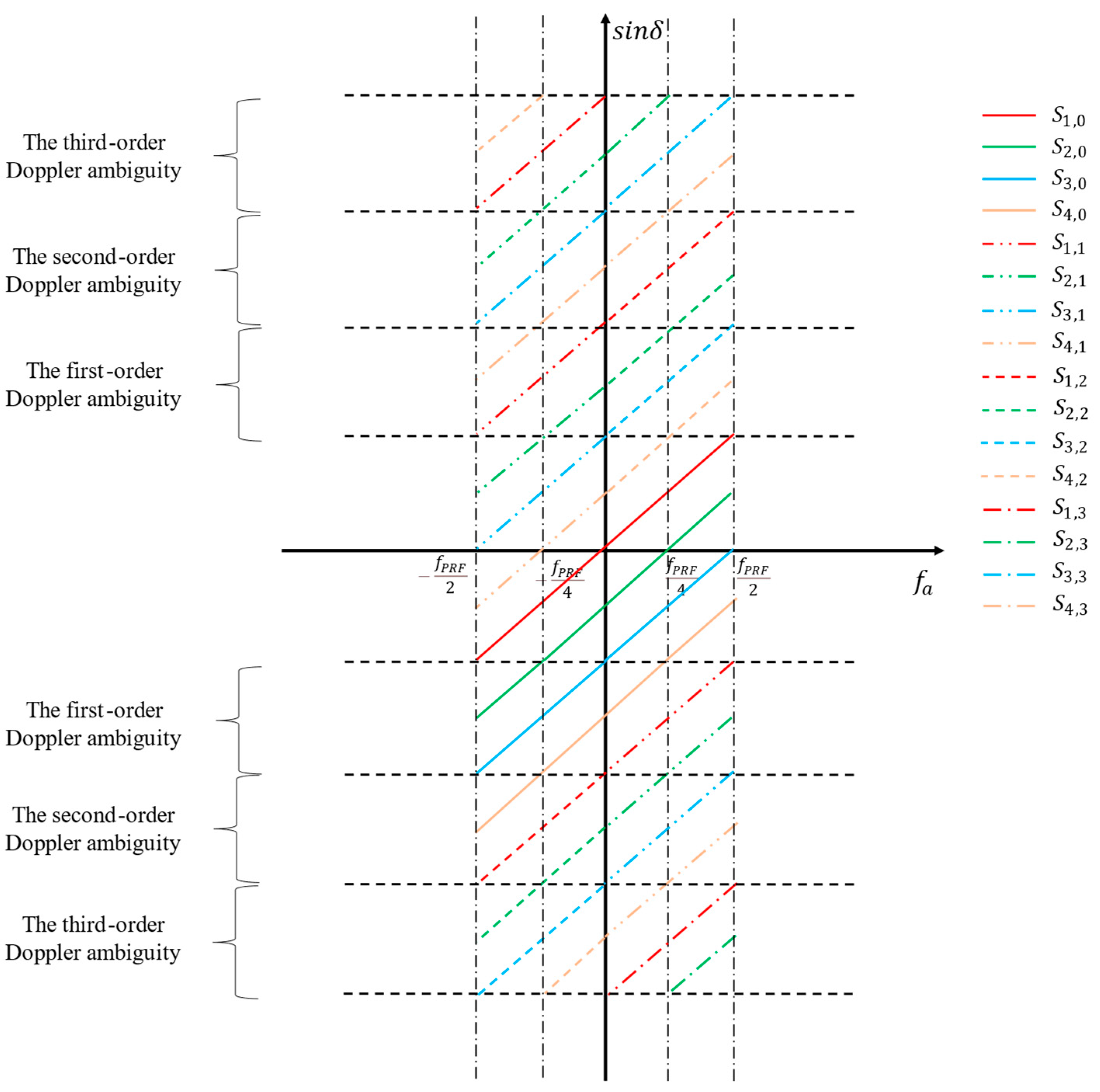
Taking and as an example, Figure 4 depicts the relationship between the four APC waveforms with third-order Doppler ambiguity in the Doppler domain.
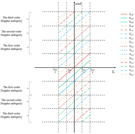
Figure 4.
The schematic diagram of APC waveform echoes with multi-order Doppler ambiguity in the Doppler domain.
Due to the presence of azimuth ambiguity, there are 16 azimuth DOAs for each Doppler frequency in Figure 4, and the relationship between the directions of different APC waveform Doppler ambiguity components constantly changes with . To simultaneously separate multiple order Doppler ambiguity components of APC waveforms, it is necessary to perform azimuth DBF on the up-sampled echoes at each Doppler frequency, and the beams point to the desired Doppler ambiguity component of the desired APC waveform while achieving null at other Doppler ambiguity components and waveforms. Notably, to realize sufficient null directions for azimuth DBF, the number of azimuth elements needs to meet .
Under multi-order Doppler ambiguity, the azimuth steering vector corresponding to the -th order Doppler ambiguity component of the -th APC waveform can be represented as
where denotes the matrix transpose operation. The weight of the azimuth DBF can be expressed as
where represents the matrix inverse or pseudo-inverse operation; denotes the null vector with elements, and only the -th element is 1. The matrix can be represented as
The process of azimuth DBF in the Doppler domain after up-sampling the echo received by each azimuth element can be expressed as
where represents the reconstructed -th APC waveform echo obtained from the separation of azimuth DBF; denotes the azimuth slow time after up-sampling; is the echo received by the -th azimuth element through azimuth up-sampling; stands for the azimuth slow-time Fourier transform; and represents the azimuth slow-time inverse Fourier transform.
According to Figure 3, due to range ambiguity, the APC waveform echoes will be received after multiple PRIs. From Equation (1), APC incorporates a phase that varies linearly with azimuth slow time, generating modulated phase related to range ambiguity order in the reconstructed APC waveform echoes after azimuth DBF. Phase demodulation cannot be uniformly performed on different APC waveform echoes. The demodulation process of the reconstructed -th APC waveform echo can be expressed as
where represents the echo of the -th APC waveform without Doppler ambiguity after demodulation.
3.2. Further Suppression of Range Ambiguity with Elevation Nulling DBF
After azimuth DBF, this scheme achieves the simultaneous suppression of range ambiguity and azimuth ambiguity. The suppression ability depends on the nulling ability of azimuth DBF in unexpected directions. In order to enhance the ability of range ambiguity suppression, this article adopts elevation nulling DBF after range compression, forming nulls in the corresponding range ambiguity direction to realize suppression. From Figure 2 and Figure 3, it can be seen that, due to the different DOAs in the elevation direction of the echoes in different sub-regions, the elevation nulling DBF can be used to retain the energy of required DOAs and suppress the ambiguous energy of unwanted DOAs. Notably, when the number of elevation elements meets , sufficient nulls can be achieved to generate a satisfying suppression effect.
Through Equation (13), range compression is performed on the echoes in each elevation element, expressed as
where represents the range fast-time Fourier transform; stands for the range fast-time inverse Fourier transform; represents the matched filter of the -th APC waveform; and denotes the result of the range compression of .
According to Equation (5), the elevation steering vector corresponding to the echo of the -th APC waveform can be expressed as
The elevation nulling DBF weight of the -th range sub-region can be expressed as
where represents the null vector with elements, of which only the -th element is 1. The matrix can be represented as
Based on Equation (14), elevation nulling DBF is conducted on the echo of each APC waveform after range compression, expressed as
where represents the echo of the -th APC waveform after elevation nulling DBF, and denotes the echo of the -th APC waveform after the range compression of the -th element in the elevation direction.
After elevation nulling DBF, the echoes of the APC waveforms without two-dimensional ambiguity are obtained. The azimuth compression algorithm can be used to derive range sub-region images without ambiguity. The azimuth compression methods include the range-Doppler algorithm (RDA) and chirp scaling algorithm (CSA). This article adopts RDA in the simulation.
3.3. Algorithm Flow
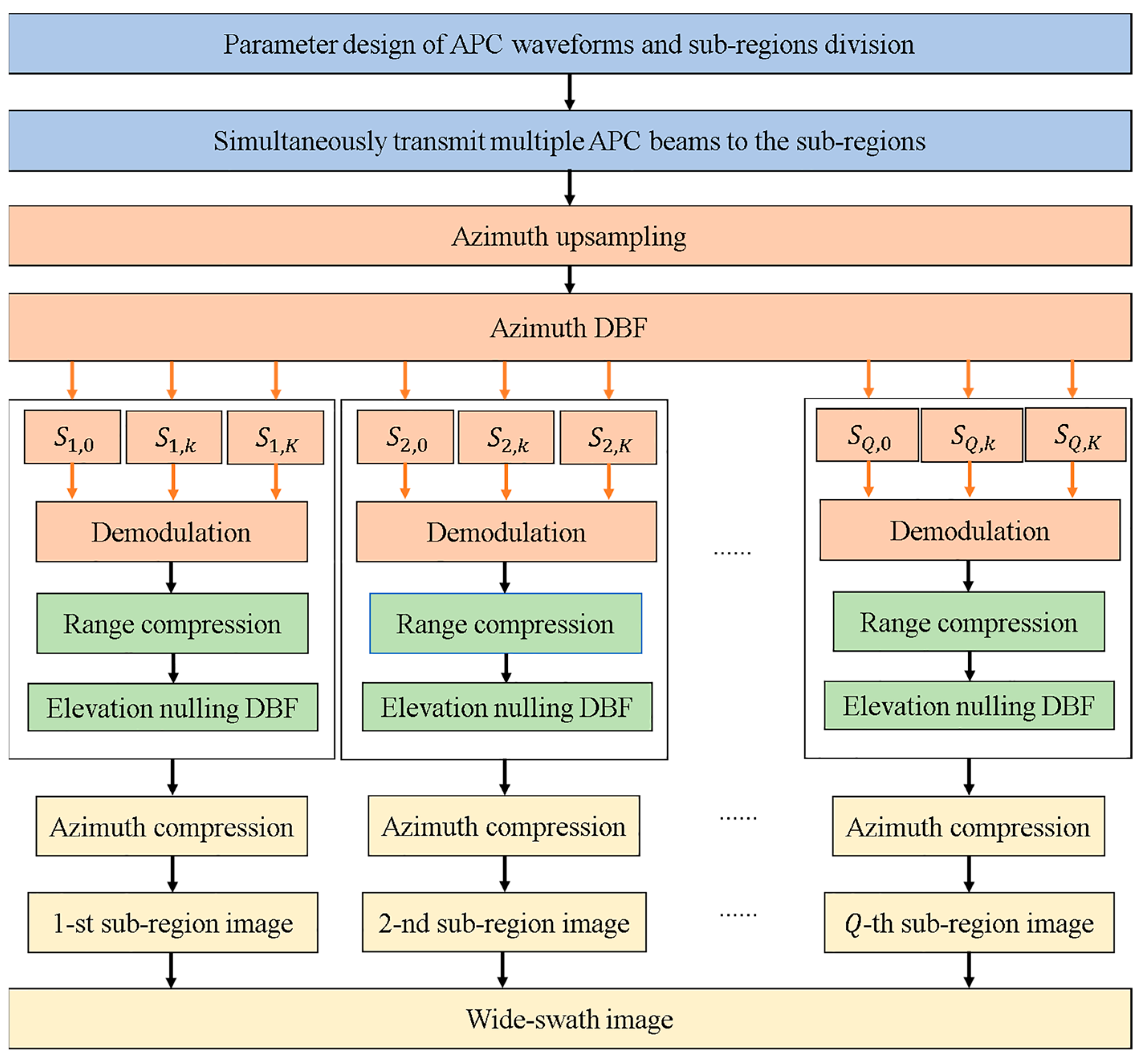
This article proposes a multi-beam SAR two-dimensional ambiguity suppression scheme based on APC. In order to further describe the proposed scheme, Figure 5 illustrates a flowchart of the ambiguity suppression scheme, and the specific steps are described below.
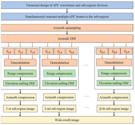
Figure 5.
The flowchart of the proposed scheme.
Step 1: Parameter design for APC waveforms and range sub-region division. Based on the imaging swath, design the number of range sub-regions, the range ambiguity order of the echo of each sub-region, the Doppler ambiguity order, the number of elements in the elevation and azimuth direction, and the APC waveforms.
Step 2: Based on the designed APC waveforms, multiple beams are simultaneously transmitted in the elevation direction to ambiguous sub-regions.
Step 3: After the echoes of APC waveforms are received by the receiving elements, up-sampling is carried out on the echo of each receiving element through spaced null-padding in the azimuth direction. The azimuth DBF separates APC waveform echoes with multi-order Doppler ambiguity to achieve simultaneous suppression of azimuth ambiguity and range ambiguity.
Step 4: Based on the designed encoding phase form and the range ambiguity order, after azimuth DBF and reconstruction, the APC waveform echoes are demodulated to eliminate Doppler modulation.
Step 5: By sequentially performing range compression and elevation nulling DBF on the echoes of APC waveforms, nulls are formed in the direction of range ambiguity to further suppress it.
Step 6: Azimuth compression is employed for the azimuth focusing of echoes of range sub-regions to obtain unambiguous images of range sub-regions.
Step 7: The imaging results of sub-regions are spliced to fulfill SAR wide-swath imaging under two-dimensional ambiguity.
The proposed scheme in this article utilizes azimuth multi-channel DBF to simultaneously suppress range ambiguity and azimuth ambiguity, enlarging the maximum unambiguous range, realizing range ambiguity suppression, and diminishing the impact of height fluctuations in the range direction on range ambiguity suppression. Meanwhile, the use of elevation nulling DBF further improves the ability to suppress ambiguity. In addition, in this scheme, the transmission power and bandwidth of different range sub-regions can be controlled flexibly, ensuring the feasibility of multiple range resolutions for various range sub-regions.
4. Experiment
This section conducts experiments using simulated point-like target data and distributed target data, respectively. The effectiveness of the multi-beam SAR two-dimensional ambiguity suppression scheme based on APC is verified. The experimental parameters are listed in Table 1. Particularly, the selected PRF is about a quarter of the Doppler bandwidth of the echo in each range sub-region, so the echo is azimuth ambiguous. Four APC waveforms that are orthogonal to each other in the Doppler domain are simultaneously transmitted into four range-ambiguous sub-regions. When using any sub-region as the reference, the other three observed sub-regions are range ambiguous.

Table 1.
Simulation system parameters.
4.1. Simulation with Point-like Targets
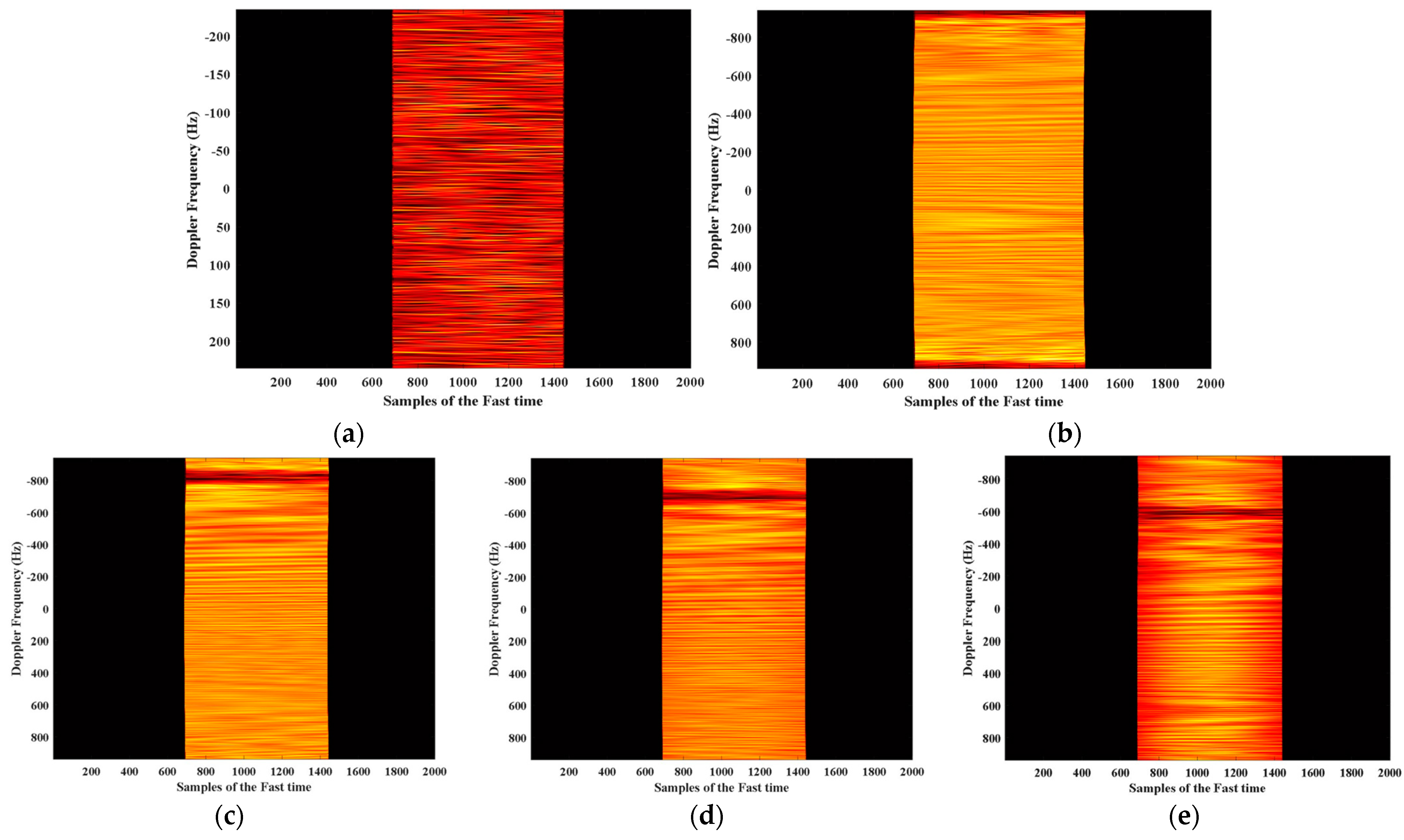
In Figure 6, one static point-like target is set within each range sub-region. Figure 6a shows the range-Doppler domain result of the echo with two-dimensional ambiguity. Figure 6b–e presents four APC waveform echoes after azimuth reconstruction and waveform separation using azimuth DBF. The echoes of different waveforms have different shifts in the Doppler domain, resulting in different APC waveform echoes within the same Doppler frequency unit having different azimuth DOAs. Therefore, while conducting azimuth reconstruction, it is possible to extract the multi-order Doppler ambiguity components of each APC waveform echo. Noticeably, after azimuth up-sampling and DBF, the equivalent PRF increases by three times compared to before.
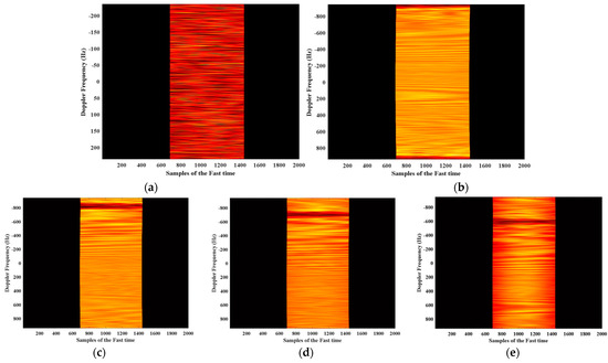
Figure 6.
The echoes in range-Doppler domain of different APC waveforms before and after azimuth DBF. (a) The two-dimensional ambiguous echo. (b) The 1-st APC waveform echo after azimuth DBF. (c) The 2-nd APC waveform echo after azimuth DBF. (d) The 3-rd APC waveform echo after azimuth DBF. (e) The 4-th APC waveform echo after azimuth DBF.
In order to further demonstrate the two-dimensional ambiguity suppression ability of the proposed scheme, a comparative experiment with the same parameters as Table 1 is designed. The difference is that LFM signals without phase coding are adopted in the comparative experiment. Therefore, four azimuth elements are used to suppress azimuth ambiguity in the comparative experiment.
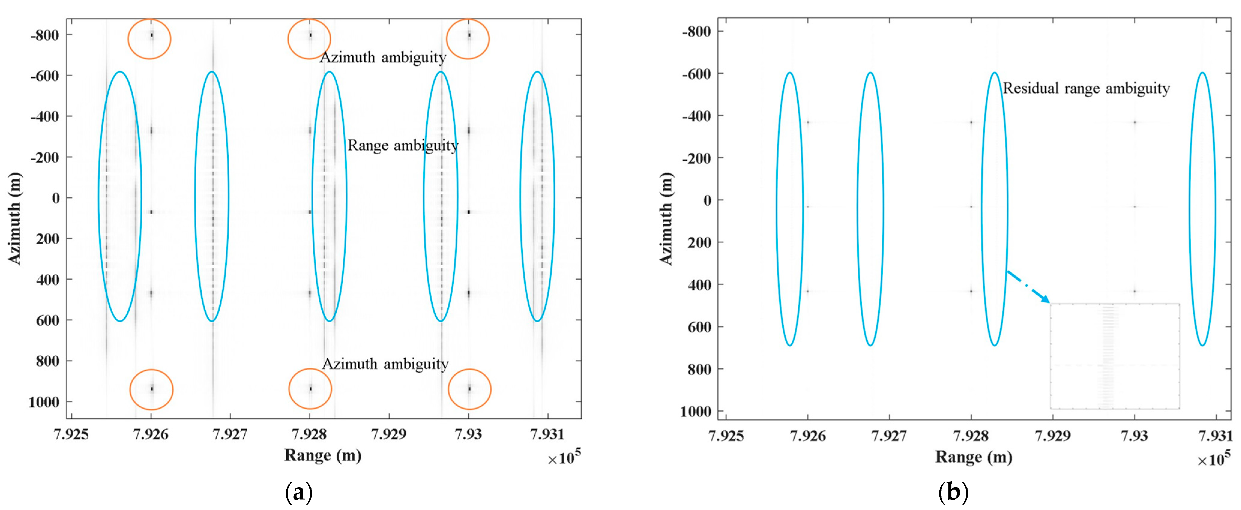
Figure 7a depicts the direct imaging result of two-dimensional ambiguous echo in the comparative experiment. It indicates that the traditional imaging method cannot directly image two-dimensional ambiguous echo, leading to azimuth ambiguity and range ambiguity. This article takes the nearest range sub-region as an example to compare the effects of ambiguity suppression. Figure 7b shows the suppression result of azimuth ambiguity and range ambiguity after azimuth DBF using the proposed scheme. It can be seen that the proposed scheme converts range ambiguity suppression into azimuth ambiguity suppression. By separating the echoes of APC waveforms through azimuth DBF, the azimuth reconstruction of APC waveform echoes is achieved while suppressing azimuth ambiguity and massive range ambiguity.
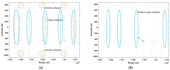
Figure 7.
The imaging result of the comparative experiment and the proposed scheme after azimuth DBF. (a) The comparative experiment. (b) The proposed scheme after azimuth DBF.
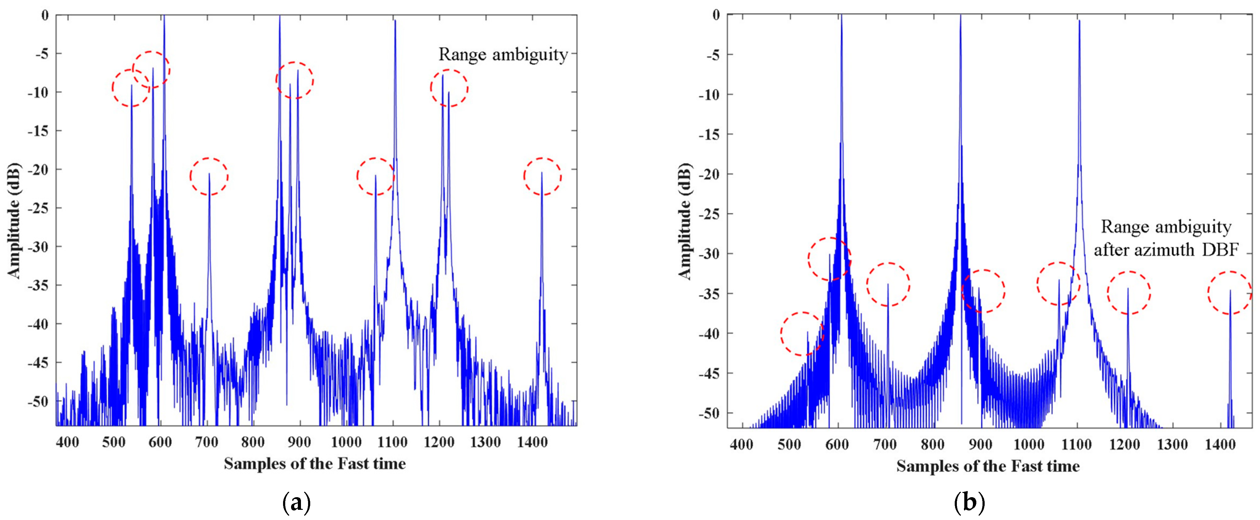
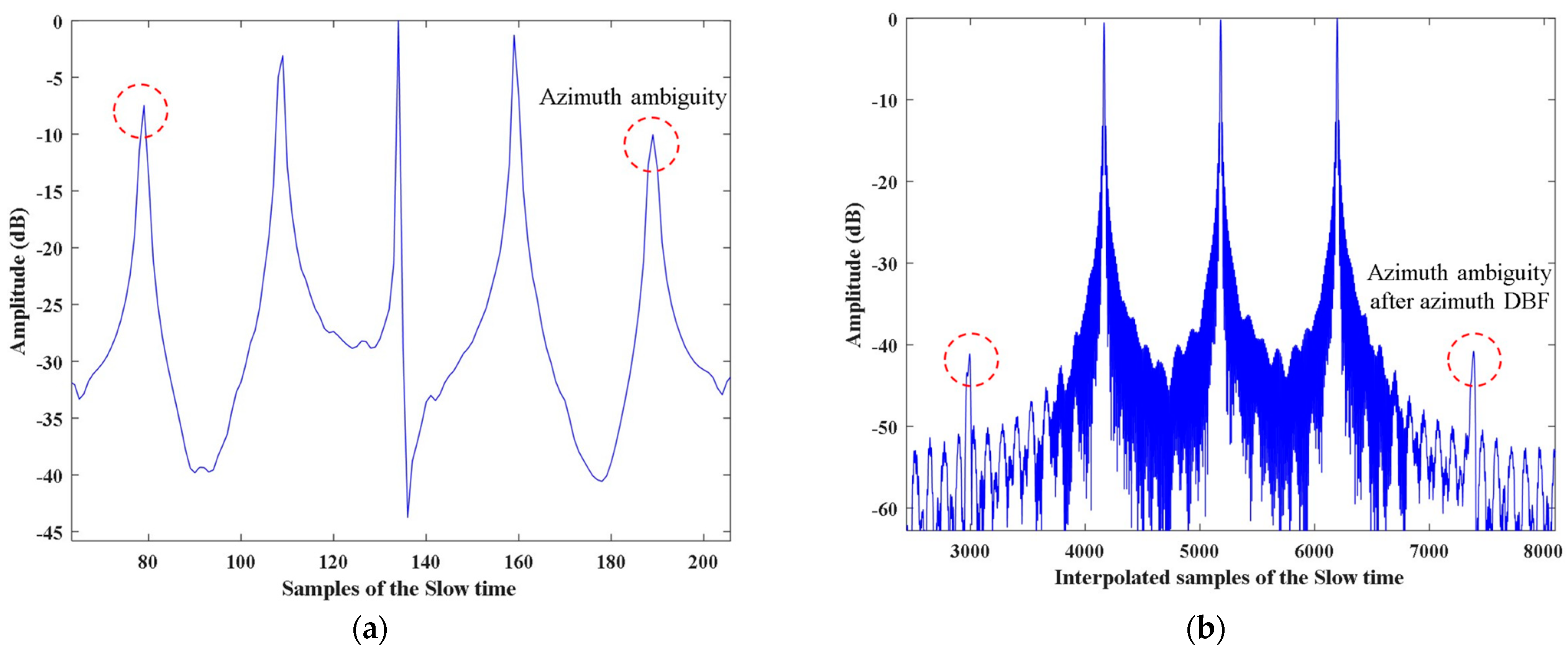
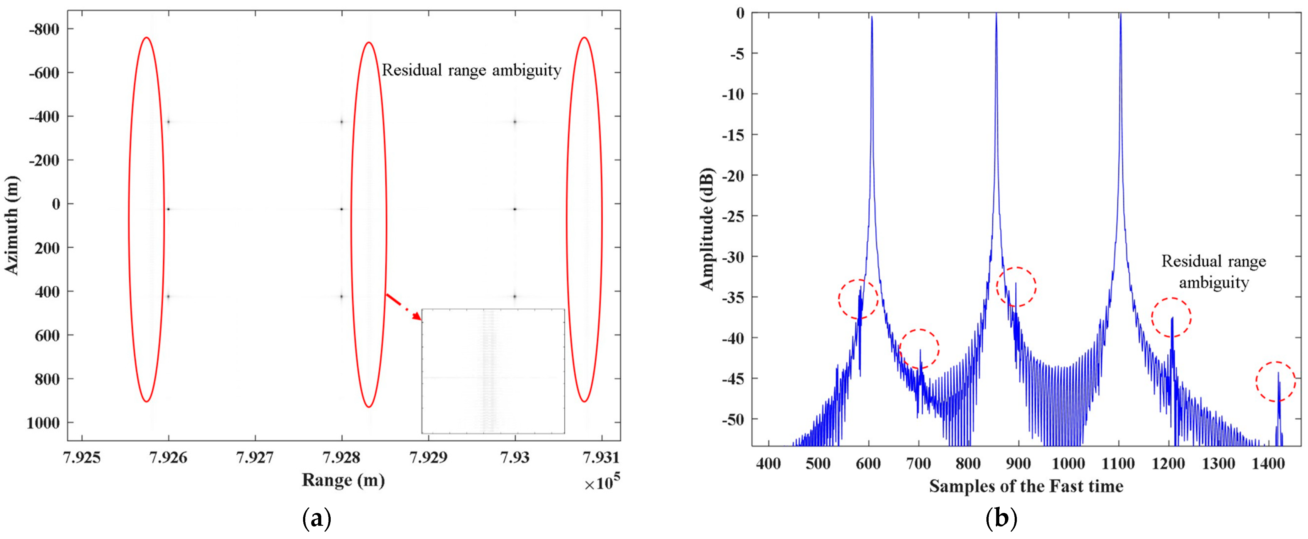
The numerical analysis results of the two-dimensional ambiguity suppression ability in Figure 7 are shown in Figure 8 and Figure 9. Figure 8a,b analyzes the range ambiguity suppression ability of the azimuth DBF. Compared to two-dimensional ambiguous echo, the azimuth DBF proposed in this article achieves about 25 dB of range ambiguity suppression effect. However, there is still minor residual range ambiguity. Figure 9a,b exhibits the analysis of the azimuth ambiguity suppression ability of azimuth DBF. After azimuth reconstruction, azimuth DBF yields about 35 dB of azimuth ambiguity suppression effect, basically achieving the goal of two-dimensional ambiguity suppression.
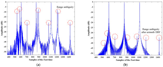
Figure 8.
The numerical analysis of the range ambiguity suppression ability of azimuth DBF of the proposed scheme. (a) The range profile of the two-dimensional ambiguous echo imaging result. (b) The range profile of the imaging result after azimuth DBF.
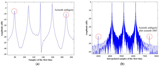
Figure 9.
The numerical analysis of the azimuth ambiguity suppression ability of azimuth DBF of the proposed scheme. (a) The azimuth profile of the two-dimensional ambiguous echo imaging result. (b) The azimuth profile of the imaging result after azimuth DBF.
To solve the problem of residual range ambiguity in Figure 8b, this article applies elevation nulling DBF to further suppress range ambiguity. Figure 10a displays the imaging result of the nearest range sub-region after elevation nulling DBF. It can be seen that the elevation nulling DBF further suppresses the residual range ambiguity based on azimuth DBF, achieving wide-swath imaging. Figure 10b illustrates the range profile of the point-like targets in Figure 10a. Elevation nulling DBF provides about 10 dB of range ambiguity suppression effect.
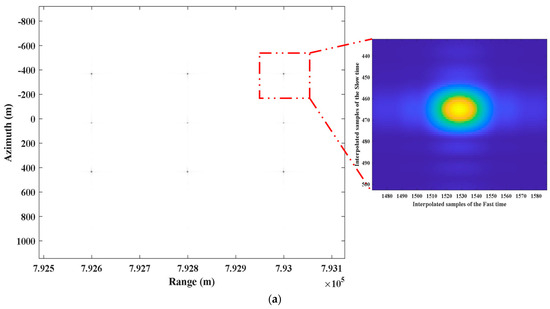
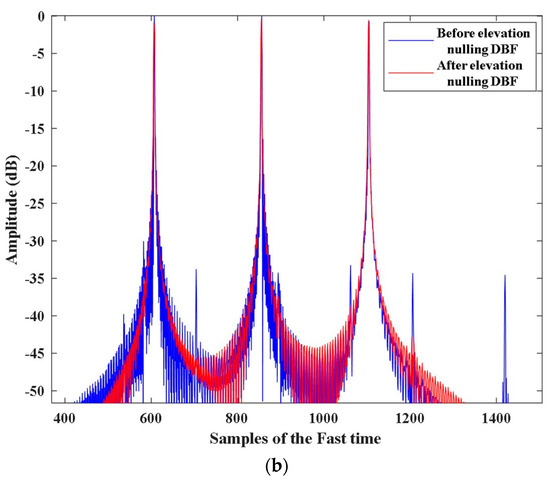
Figure 10.
The imaging result of the proposed scheme in this article. (a) The imaging result of two-dimensional ambiguous echo after two-dimensional DBF. (b) The range profile.
4.2. Simulation with Distributed Targets
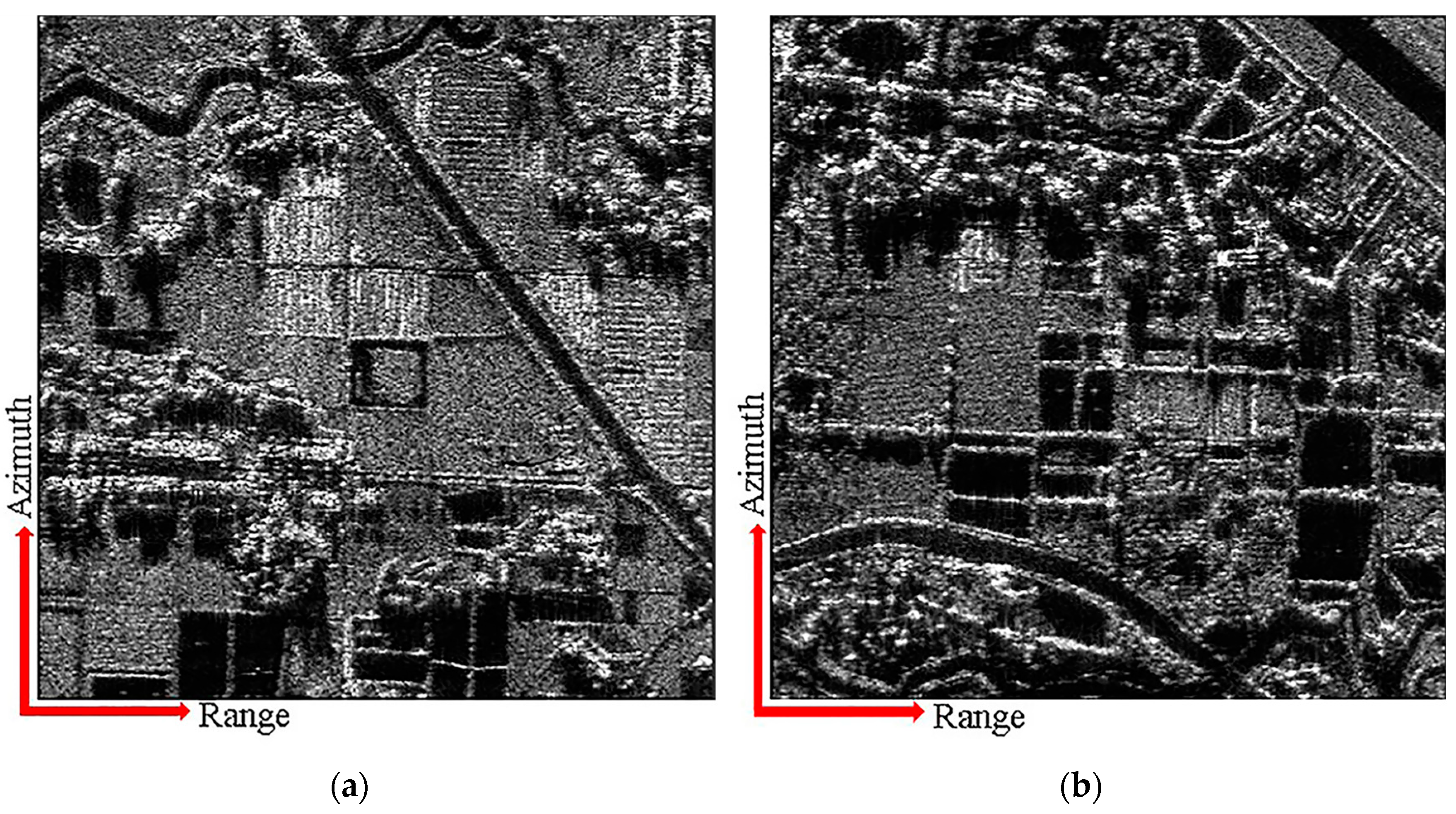
This section employs a complex scenario containing distributed targets to demonstrate the effectiveness of the proposed scheme, with the same parameters in Table 1. The distributed scene consists of four sub-regions with mutual range ambiguity, and the echoes have two-dimensional ambiguity. The proposed scheme is used to separate and reconstruct the APC waveform echo of each sub-region. Elevation nulling DBF is adopted to further suppress range ambiguity. Finally, RDA is employed to obtain imaging results of various range-ambiguous sub-regions. Figure 11 exhibits the imaging results of range-ambiguous sub-regions after azimuth DBF. Plenty of range ambiguity is suppressed by azimuth DBF, and only a little remains in range sub-regions.
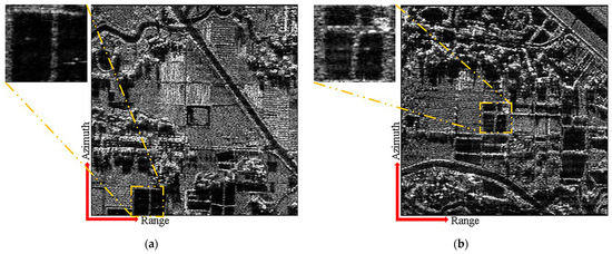
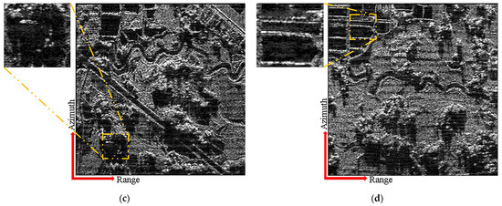
Figure 11.
The imaging results of two-dimensional ambiguous sub-regions after azimuth DBF. (a) The 1-st sub-region. (b) The 2-nd sub-region. (c) The 3-rd sub-region. (d) The 4-th sub-region.
Figure 12 shows the imaging results of range-ambiguous sub-regions after two-dimensional DBF. Comparing with Figure 11, it can be seen that, after two-dimensional DBF, the ambiguous energy in the four images almost completely disappears. After azimuth DBF, the elevation nulling DBF of the proposed scheme in this article further suppresses residual range ambiguity and improves wide-swath imaging capability.
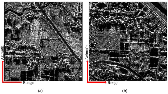
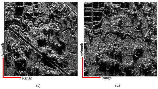
Figure 12.
The imaging results of two-dimensional ambiguous sub-regions after two-dimensional DBF. (a) The 1-st sub-region. (b) The 2-nd sub-region. (c) The 3-rd sub-region. (d) The 4-th sub-region.
4.3. Advantages Compared to Conventional Scheme
The conventional scheme mentioned in Section 4.1 is used as a comparative experiment to demonstrate the advantages of the proposed scheme in range ambiguity suppression. The conventional scheme uses azimuth DBF to achieve azimuth reconstruction and suppress azimuth ambiguity, while range ambiguity is suppressed solely through elevation nulling DBF. Figure 13a depicts the imaging result of point-like targets after two-dimensional ambiguity suppression using the conventional scheme, and Figure 13b presents the range profile of point-like targets in Figure 13a. The conventional scheme and the proposed scheme after azimuth DBF exhibit similar range ambiguity suppression capabilities, both of which have about −35 dB of residual range ambiguity.
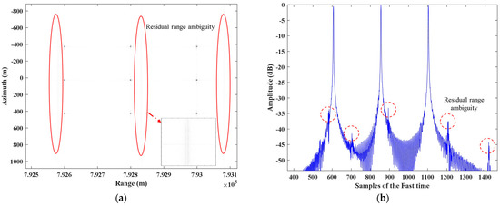
Figure 13.
The imaging result of two-dimensional ambiguous sub-region using the conventional scheme. (a) The imaging result of the conventional scheme. (b) The range profile.
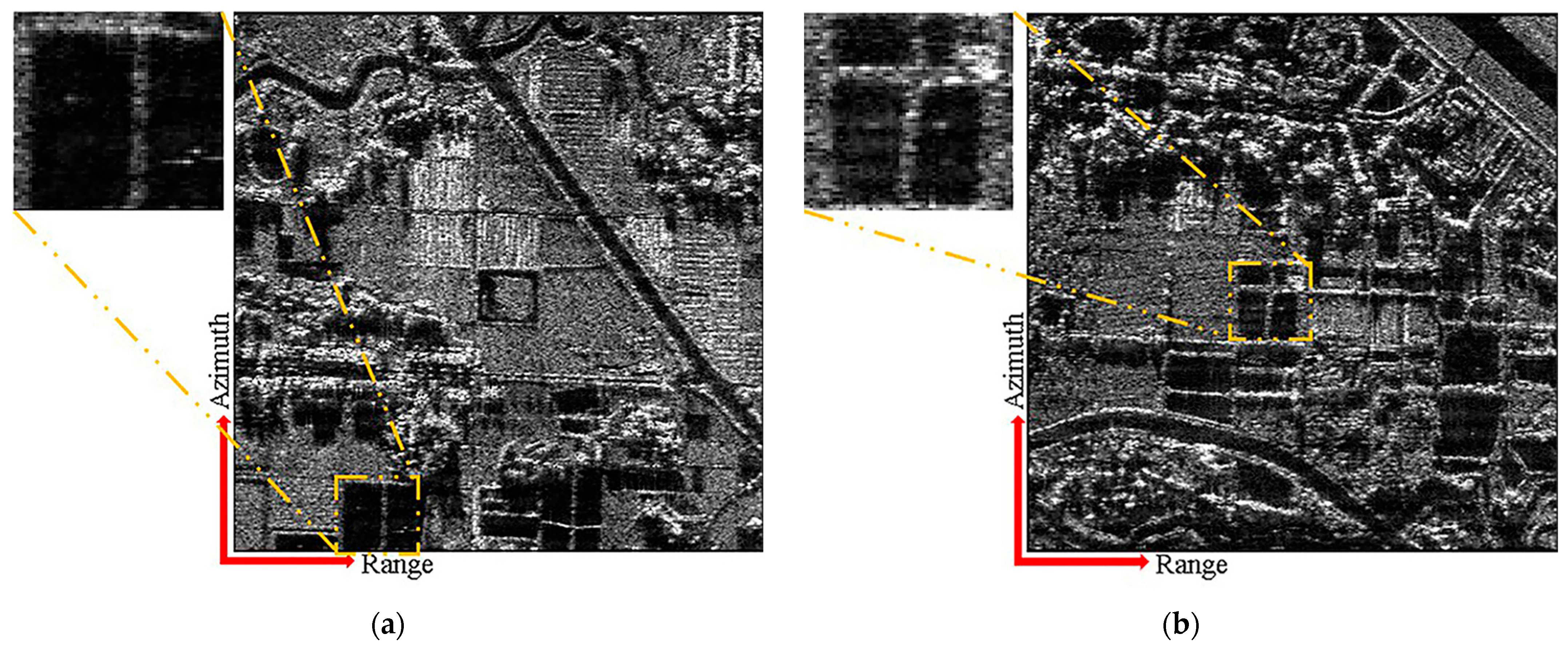
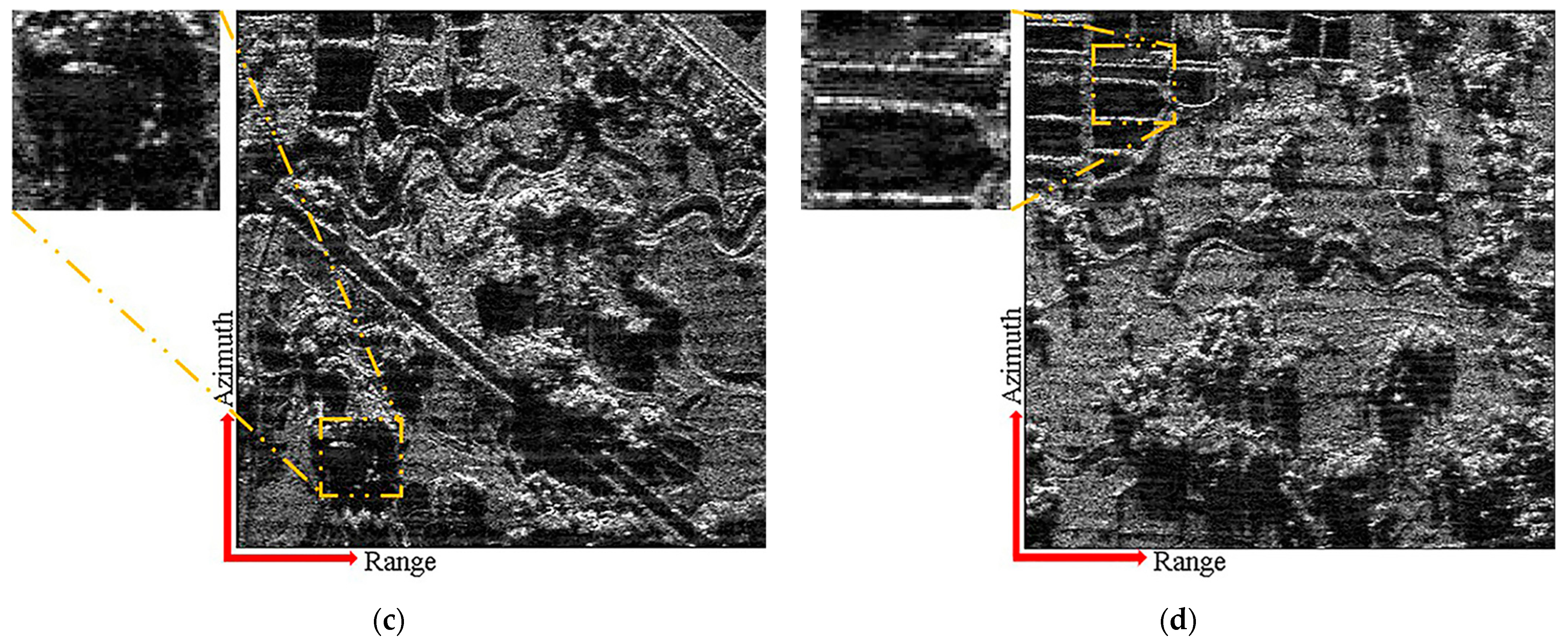
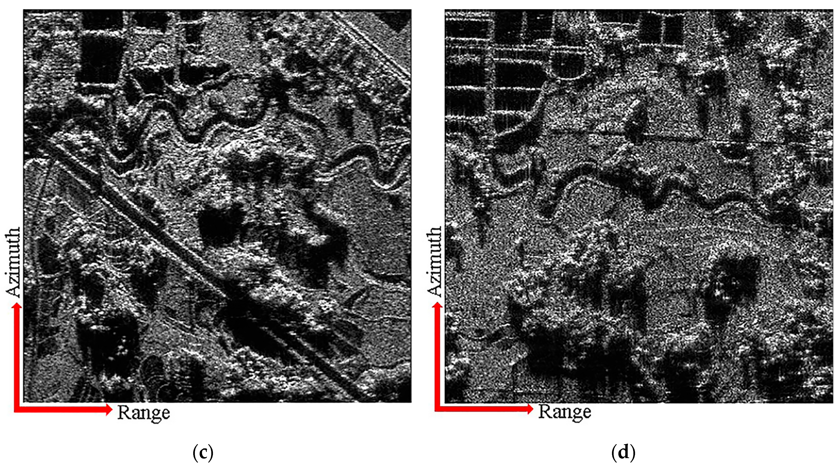
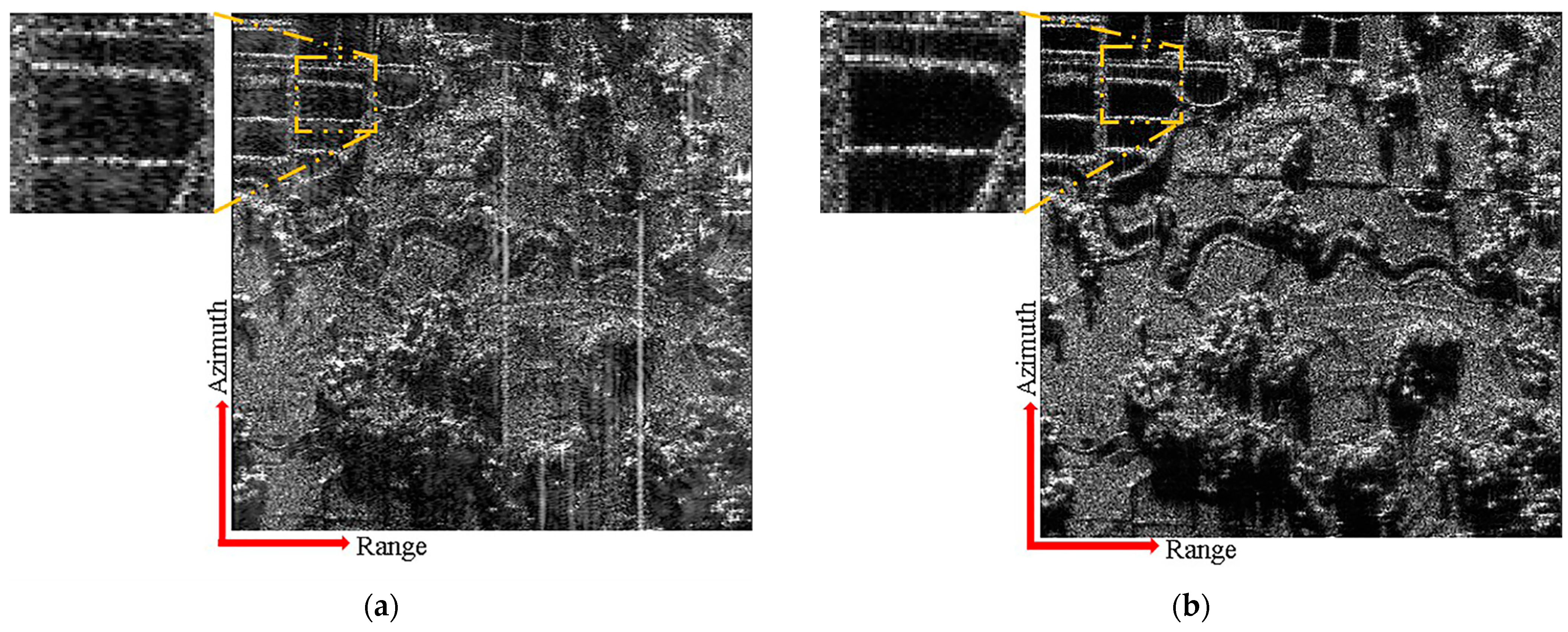
Figure 14a,b illustrates the imaging results of the distributed targets using the conventional and proposed schemes for the same range-ambiguous sub-region, respectively. In contrast with the conventional scheme, the proposed scheme uses APC waveforms to convert range ambiguity into azimuth ambiguity, and azimuth DBF simultaneously suppresses azimuth ambiguity and range ambiguity, possessing a superior range ambiguity suppression ability. Furthermore, the proposed scheme uses azimuth DBF to suppress range ambiguity, which can abate the impact of height fluctuations in the range direction on the ability to suppress range ambiguity.
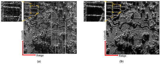
Figure 14.
The comparison of imaging results of distributed targets between conventional and proposed schemes. (a) The conventional scheme. (b) The proposed scheme.
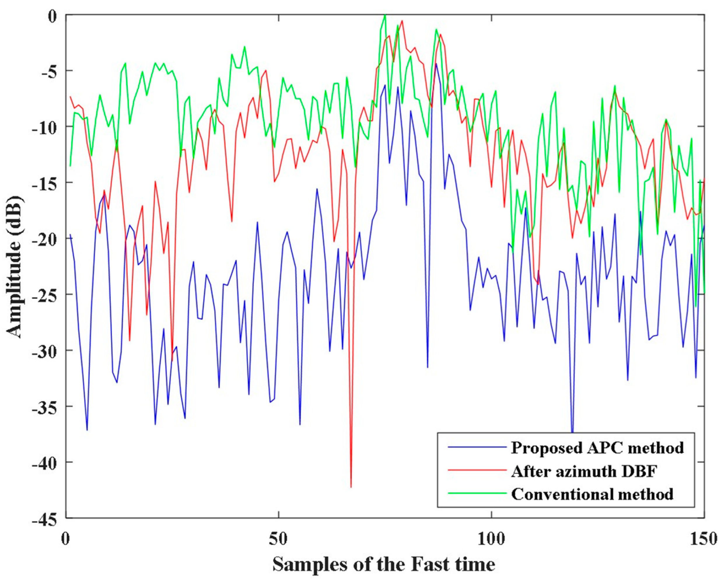
In order to elaborate on the advantages of the proposed scheme in range ambiguity suppression, Figure 15 depicts the range profile near the yellow box in Figure 14. The range ambiguity suppression effects of the proposed scheme after azimuth DBF, the proposed scheme after two-dimensional DBF, and the conventional scheme are compared. In Figure 15, only the middle portion with approximately 20 points represents the signal, while the rest can be considered as noise. Since the ambiguity energy added to the noise is often more apparent, this article compares the ambiguity suppression effect in the noise portion. It can be concluded that the azimuth DBF of the proposed scheme has a similar range ambiguity suppression capacity to that of the conventional scheme, and the final result of the proposed scheme further achieves about 10 dB of ambiguity suppression on this basis. In addition, this article also calculates the signal-to-ambiguity ratio using the signal amplitude and ambiguity amplitude for each scheme in Figure 15. By averaging the results of multiple range profiles, the signal-to-ambiguity ratios of the conventional scheme, the proposed scheme after azimuth DBF and the proposed scheme after two-dimensional DBF are −11.0 dB, −6.4 dB, and −1.1 dB, respectively. It can also be seen that the proposed scheme in this article provides about 10 dB improvement in signal-to-ambiguity ratio compared to the conventional scheme.
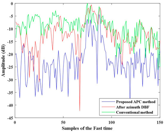
Figure 15.
The range profile of distributed targets.
5. Conclusions
This article proposes a multi-beam SAR two-dimensional ambiguity suppression scheme based on APC. Under the condition of azimuth under-sampling, azimuth DBF is adopted to achieve the separation and azimuth reconstruction of multi-order Doppler ambiguity components of different APC waveform echoes. Compared to conventional schemes, this scheme has a superior ambiguity suppression capacity, better adaptability to height fluctuations in the range direction, and more flexible range resolutions of various range sub-regions. The effectiveness of the proposed scheme is demonstrated through the simulation results of point-like targets and distributed targets. On this basis, future research can achieve multiple SAR imaging modes simultaneously in diverse sub-regions. In addition, the scheme proposed in this article has the potential to achieve SAR imaging of moving targets in wide-swath scenes.
Author Contributions
Conceptualization, Y.X., Y.W. and L.C.; Data curation, Y.X., F.Z. and Y.W.; Formal analysis, Y.X., F.Z. and W.L.; Funding acquisition, L.C. and F.Z.; Investigation, Y.X., F.Z. and T.J.; Methodology, Y.X., F.Z. and L.C.; Project administration, Y.X., Y.W. and L.C.; Resources, F.Z. and L.C.; Software, Y.X., W.L. and T.J.; Supervision, Y.X., F.Z. and L.C.; Validation, Y.X., F.Z. and Y.W.; Visualization, Y.X.; Writing—original draft, Y.X.; Writing—review and editing, Y.X., F.Z. and Y.W. All authors have read and agreed to the published version of the manuscript.
Funding
This work was supported by the National Key R&D Program of China, 2022YFB3901601.
Data Availability Statement
The data presented in this study are available on request from the corresponding author. The data are not publicly available due to privacy restrictions.
Acknowledgments
All authors would like to thank the Aerospace Information Research Institute, Chinese Academy of Sciences for providing the laboratory conditions. All authors are thankful to the editor and the anonymous reviewers for their time.
Conflicts of Interest
The authors declare no conflicts of interest.
References
- Wei, J.; Li, Y.; Yang, R.; Li, L.; Guo, L. Method of high signal-to-noise ratio and wide swath SAR imaging based on continuous pulse coding. IEEE J. Sel. Top. Appl. Earth Obs. Remote Sens. 2022, 15, 2185–2196. [Google Scholar] [CrossRef]
- Guo, Y.; Wang, Y.; Liao, G.; Li, J. Mitigating Range Ambiguity Method Based on DDMA for SAR Systems. Remote Sens. 2022, 14, 5485. [Google Scholar] [CrossRef]
- Freeman, A.; Johnson, W.T.K.; Huneycutt, B.; Jordan, R.; Hensley, S.; Siqueira, P.; Curlander, J. The “Myth” of the minimum SAR antenna area constraint. IEEE Trans. Geosci. Remote Sens. 2000, 38, 320–324. [Google Scholar] [CrossRef]
- He, F.; Dong, Z.; Zhang, Y.; Jin, G.; Yu, A. Processing of spaceborne squinted sliding spotlight and HRWS TOPS mode data using 2-D baseband azimuth scaling. IEEE Trans. Geosci. Remote Sens. 2019, 58, 938–955. [Google Scholar] [CrossRef]
- Chen, Y.; Zhao, Y.; Li, G.; Wang, W.; Liu, P. High-Resolution and Wide-Swath Monostatic SAR Imaging via Random Beam Scanning. In Proceedings of the 2020 IEEE 11th Sensor Array and Multichannel Signal Processing Workshop (SAM), Hangzhou, China, 8–11 June 2020; IEEE: Piscataway, NJ, USA, 2020; pp. 1–5. [Google Scholar] [CrossRef]
- Lightstone, L.; Faubert, D.; Rempel, G. Multiple phase centre DPCA for airborne radar. In Proceedings of the 1991 IEEE National Radar Conference, Los Angeles, CA, USA, 12–13 March 1991; IEEE: Piscataway, NJ, USA, 1991; pp. 36–40. [Google Scholar] [CrossRef]
- Krieger, G.; Gebert, N.; Moreira, A. Unambiguous SAR signal reconstruction from nonuniform displaced phase center sampling. IEEE Geosci. Remote Sens. Lett. 2004, 1, 260–264. [Google Scholar] [CrossRef]
- Krieger, G.; Gebert, N.; Moreira, A. SAR signal reconstruction from non-uniform displaced phase centre sampling. In Proceedings of the IGARSS 2004. 2004 IEEE International Geoscience and Remote Sensing Symposium, Anchorage, AK, USA, 20–24 September 2004; IEEE: Piscataway, NJ, USA, 2004; Volume 3, pp. 1763–1766. [Google Scholar] [CrossRef]
- Zhang, S.-X.; Xing, M.-D.; Xia, X.-G.; Zhang, L.; Guo, R.; Liao, Y.; Bao, Z. Multichannel HRWS SAR imaging based on range-variant channel calibration and multi-Doppler-direction restriction ambiguity suppression. IEEE Trans. Geosci. Remote Sens. 2013, 52, 4306–4327. [Google Scholar] [CrossRef]
- Gebert, N. Multi-Channel Azimuth Processing for High-Resolution Wide-Swath; Universitat (TH), DLR-Forschungsbericht: Wessling, Germany, 2009. [Google Scholar]
- Castillo, J.; Younis, M.; Krieger, G. A HRWS SAR system design with multi-beam imaging capabilities. In Proceedings of the 2017 European Radar Conference (EURAD), Nuremberg, Germany, 11–13 October 2017; IEEE: Piscataway, NJ, USA, 2017; pp. 179–182. [Google Scholar] [CrossRef]
- Huang, Y.; Liao, G.; Xu, J.; Li, J.; Yang, D. GMTI and parameter estimation for MIMO SAR system via fast interferometry RPCA method. IEEE Trans. Geosci. Remote Sens. 2017, 56, 1774–1787. [Google Scholar] [CrossRef]
- Krieger, G. MIMO-SAR: Opportunities and pitfalls. IEEE Trans. Geosci. Remote Sens. 2013, 52, 2628–2645. [Google Scholar] [CrossRef]
- Lan, L.; Xu, J.; Liao, G.; Zhang, Y.; Fioranelli, F.; So, H.C. Suppression of mainbeam deceptive jammer with FDA-MIMO radar. IEEE Trans. Veh. Technol. 2020, 69, 11584–11598. [Google Scholar] [CrossRef]
- Xu, W.; Huang, P.; Tan, W. Azimuth phase coding by up and down chirp modulation for range ambiguity suppression. IEEE Access 2019, 7, 143780–143791. [Google Scholar] [CrossRef]
- Yu, K.; Zhu, S.; Lan, L.; Yang, B. High-Resolution and Wide-Swath SAR Imaging with Space–Time Coding Array. Remote Sens. 2023, 15, 2465. [Google Scholar] [CrossRef]
- Zhang, M.; Liao, G.; Xu, J.; Lan, L.; Zhu, S.; Xing, M.; He, X. High-Resolution and Wide-Swath Imaging Based on Multifrequency Pulse Diversity and DPCA Technique. IEEE Geosci. Remote Sens. Lett. 2021, 19, 1–5. [Google Scholar] [CrossRef]
- Wang, W.Q. Mitigating range ambiguities in high-PRF SAR with OFDM waveform diversity. IEEE Geosci. Remote Sens. Lett. 2012, 10, 101–105. [Google Scholar] [CrossRef]
- Riche, V.; Meric, S.; Baudais, J.-Y.; Pottier, E. Investigations on OFDM signal for range ambiguity suppression in SAR configuration. IEEE Trans. Geosci. Remote Sens. 2013, 52, 4194–4197. [Google Scholar] [CrossRef]
- Wang, C.; Xu, J.; Liao, G.; Xu, X.; Zhang, Y. A range ambiguity resolution approach for high-resolution and wide-swath SAR imaging using frequency diverse array. IEEE J. Sel. Top. Signal Process. 2016, 11, 336–346. [Google Scholar] [CrossRef]
- Xu, J.; Zhu, S.; Liao, G. Range ambiguous clutter suppression for airborne FDA-STAP radar. IEEE J. Sel. Top. Signal Process. 2015, 9, 1620–1631. [Google Scholar] [CrossRef]
- Jin, G.; Wang, W.; Deng, Y.; Yan, H.; Wang, R. A novel range-azimuth joint modulation scheme for range ambiguity suppression. IEEE Trans. Geosci. Remote Sens. 2021, 60, 1–10. [Google Scholar] [CrossRef]
- Niu, S.; Zhu, D.; Jin, G.; Cheng, Y.; Wang, Y. A novel transmitter-interpulse phase coding MIMO-radar for range ambiguity separation. IEEE Trans. Geosci. Remote Sens. 2022, 60, 1–16. [Google Scholar] [CrossRef]
- Jin, G.; Wang, Y.; Zhu, D.; Niu, S.; Yan, H. A reconfigurable MIMO-SAR transmission scheme based on inter-pulse and intra-pulse joint phase modulation. IEEE Trans. Signal Process. 2022, 70, 4265–4276. [Google Scholar] [CrossRef]
- Wang, H.; Zhang, Y.; Xu, J.; Liao, G.; Zhu, S. Range ambiguity suppression in a synthetic aperture radar using pulse phase coding and two-pulse cancellation. Int. J. Remote Sens. 2018, 39, 6525–6539. [Google Scholar] [CrossRef]
- Wang, Y.; Wang, W.; Deng, Y.; Zhang, Y.; Zhao, P.; Zhang, H. A 2-D method based on nonlinear frequency modulation waveform and phase coding for range ambiguity suppression. IEEE Geosci. Remote Sens. Lett. 2023, 20, 1–5. [Google Scholar] [CrossRef]
- Wang, J.; Liang, X.-D.; Chen, L.-Y.; Li, K. A novel space–time coding scheme used for MIMO-SAR systems. IEEE Geosci. Remote Sens. Lett. 2015, 12, 1556–1560. [Google Scholar] [CrossRef]
- Zhou, F.; Ai, J.; Dong, Z.; Zhang, J.; Xing, M. A novel MIMO–SAR solution based on azimuth phase coding waveforms and digital beamforming. Sensors 2018, 18, 3374. [Google Scholar] [CrossRef] [PubMed]
- He, X.; Liao, G.; Zhu, S.; Xu, J.; Wang, C. Range-ambiguous clutter suppression for the SAR-GMTI system based on extended azimuth phase coding. IEEE Trans. Geosci. Remote Sens. 2020, 58, 8147–8162. [Google Scholar] [CrossRef]
- Zhang, Y.; Wang, W.; Deng, Y.; Yu, W.; Zhang, Z.; Zhao, P.; Wang, R. Quadratically constrained ambiguity suppression algorithm for APC/multichannel SAR systems with nonuniform spatial sampling. IEEE Trans. Geosci. Remote Sens. 2020, 59, 1319–1330. [Google Scholar] [CrossRef]
- Wang, J.; Xin, Y.; Liang, X.-D.; Chen, L.-Y.; Li, Y.-L. Inter-pulse phase modulation waveform scheme for spaceborne MIMO SAR systems. IEEE Trans. Aerosp. Electron. Syst. 2021, 57, 4051–4066. [Google Scholar] [CrossRef]


Disclaimer/Publisher’s Note: The statements, opinions and data contained in all publications are solely those of the individual author(s) and contributor(s) and not of MDPI and/or the editor(s). MDPI and/or the editor(s) disclaim responsibility for any injury to people or property resulting from any ideas, methods, instructions or products referred to in the content. |
© 2024 by the authors. Licensee MDPI, Basel, Switzerland. This article is an open access article distributed under the terms and conditions of the Creative Commons Attribution (CC BY) license (https://creativecommons.org/licenses/by/4.0/).