
Enhancing Clay-Based 3D-Printed Mortars with Polymeric Mesh Reinforcement Techniques

 ,
,  , and
, and
Abstract

1. Introduction
2. Materials and Methods
2.1. Materials
2.2. Preparation Process of Clay-Based Mortar Mixtures
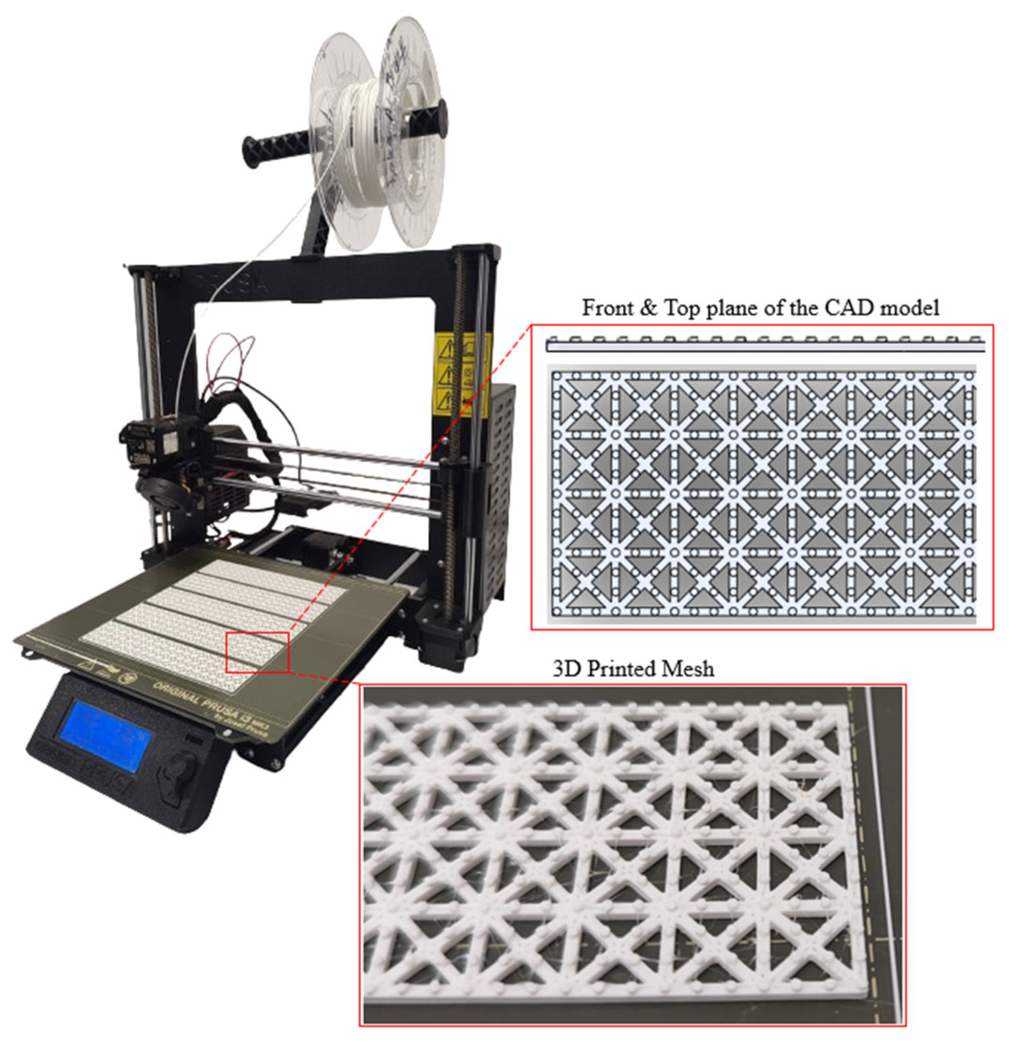
2.3. Design and 3D Printing of Reinforcing Meshes
2.4. Three-Dimensional Printing of Clay-Based Mortar Mixtures
2.5. Preparation of Molded Specimens
2.6. Materials Characterization
2.6.1. X-ray Diffraction (XRD)
2.6.2. Physical Properties
2.6.3. Mechanical Properties
3. Results
3.1. X-ray Diffraction (XRD) Measurements
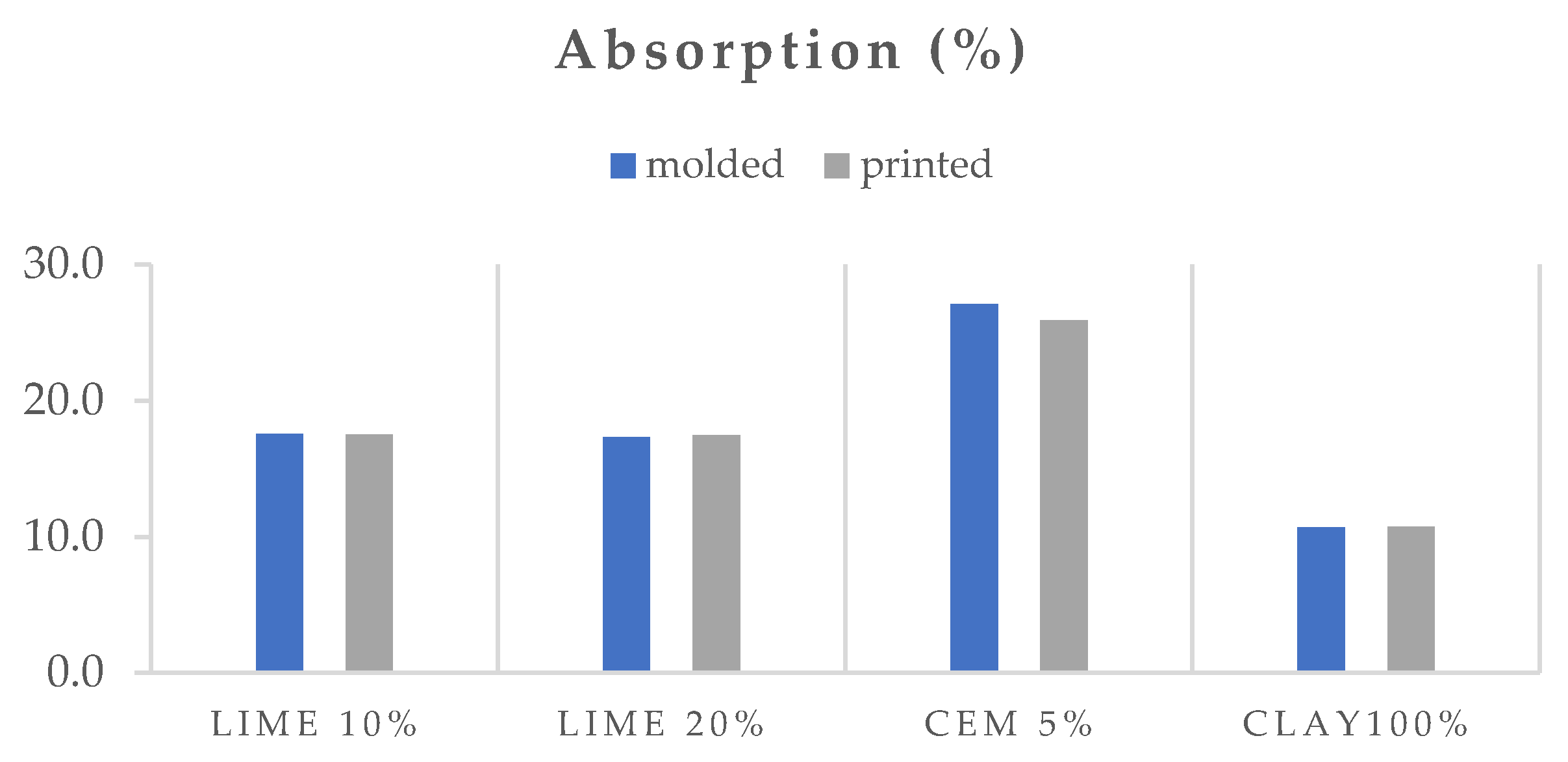
3.2. Physical Properties
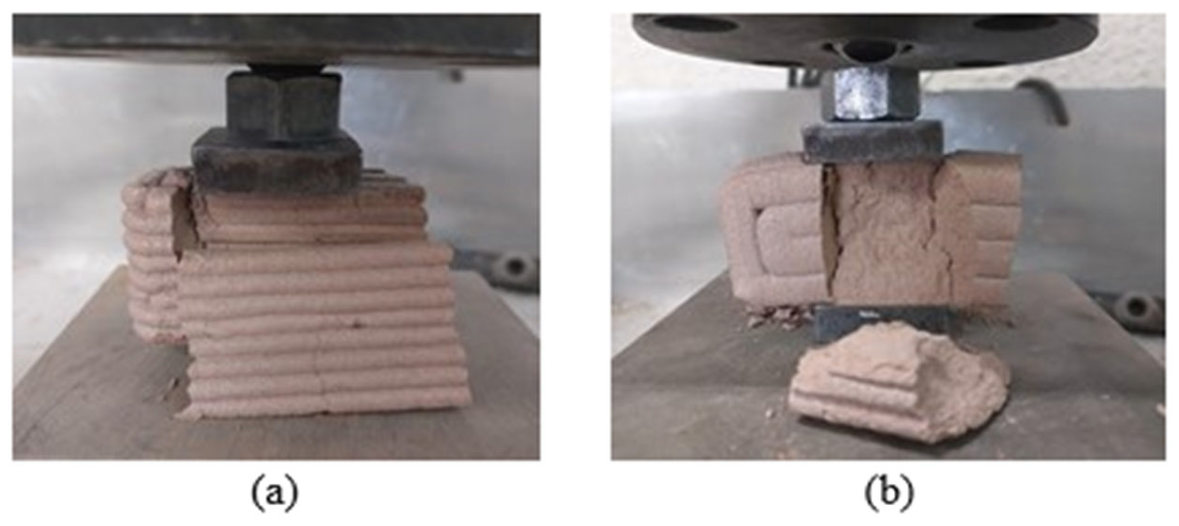
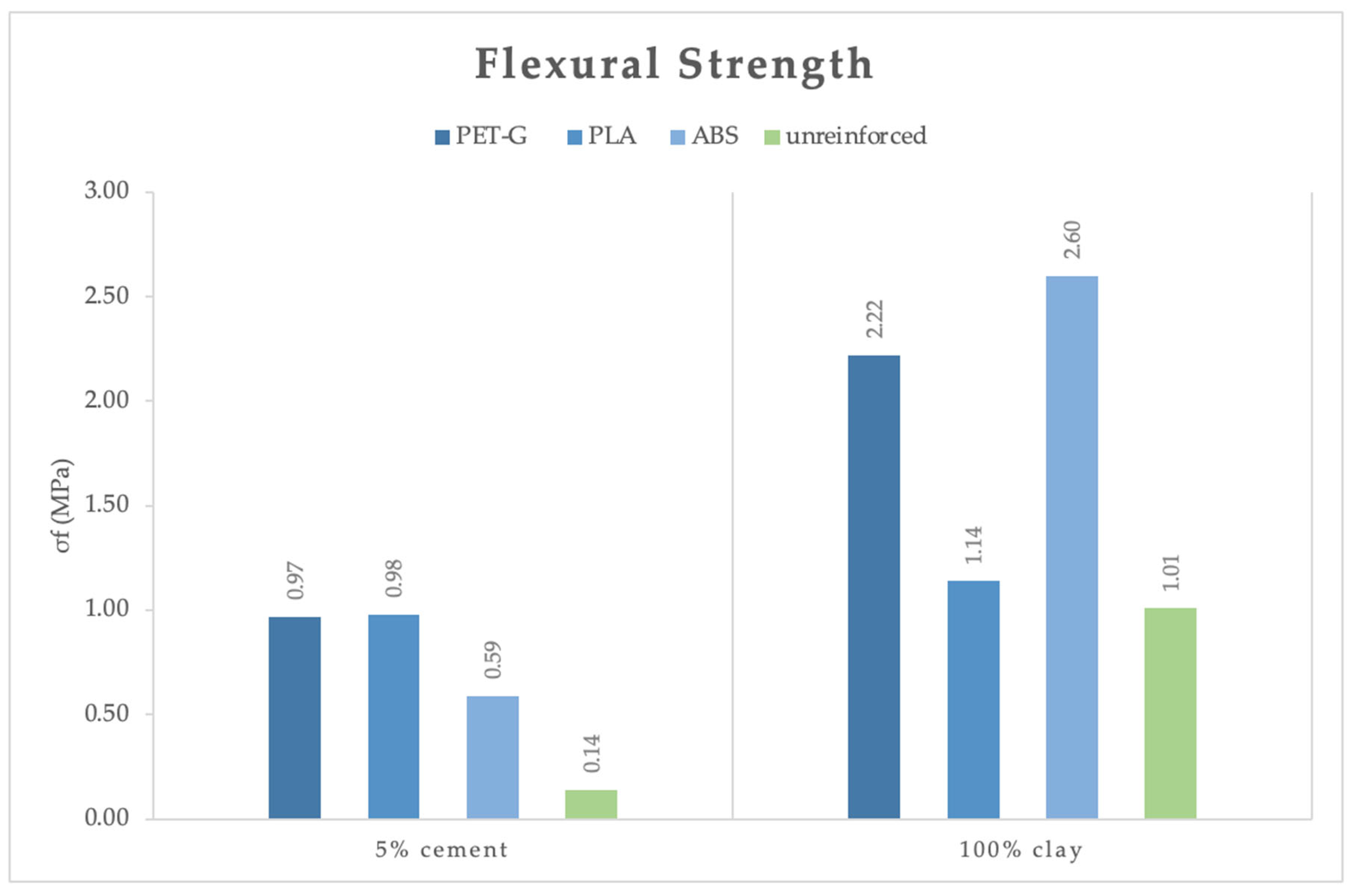
3.3. Mechanical Properties
4. Conclusions
Author Contributions
Funding
Institutional Review Board Statement
Data Availability Statement
Conflicts of Interest
References
- Xu, J.; Ding, L.; Love, P.E.D. Digital reproduction of historical building ornamental components: From 3D scanning to 3D printing. Autom. Constr. 2017, 76, 85–96. [Google Scholar] [CrossRef]
- Jo, Y.H.; Hong, S.; Jo, S.Y.; Kwon, Y.M. Noncontact restoration of missing parts of stone Buddha statue based on three-dimensional virtual modeling and assembly simulation. Herit. Sci. 2020, 8, 103. [Google Scholar] [CrossRef]
- Blavier, C.L.S.; Huerto-Cardenas, H.E.; Aste, N.; Del Pero, C.; Leonforte, F.; Della Torre, S. Adaptive measures for preserving heritage buildings in the face of climate change: A review. Build. Environ. 2023, 245, 110832. [Google Scholar] [CrossRef]
- Vidal, F.; Vicente, R.; Silva, J.M. Review of environmental and air pollution impacts on built heritage: 10 questions on corrosion and soiling effects for urban intervention. J. Cult. Herit. 2019, 37, 273–295. [Google Scholar] [CrossRef]
- Fabbri, A.; Morel, J.-C. Earthen materials and constructions. In Nonconventional and Vernacular Construction Materials; Woodhead Publishing: Sawston, UK, 2016; pp. 273–299. [Google Scholar] [CrossRef]
- Yazdani Mehr, S. Analysis of 19th and 20th Century Conservation Key Theories in Relation to Contemporary Adaptive Reuse of Heritage Buildings. Heritage 2019, 2, 61. [Google Scholar] [CrossRef]
- Turk, J.; Mauko Pranjić, A.; Hursthouse, A.; Turner, R.; Hughes, J.J. Decision support criteria and the development of a decision support tool for the selection of conservation materials for the built cultural heritage. J. Cult. Herit. 2019, 37, 44–53. [Google Scholar] [CrossRef]
- Armesto-González, J.; Riveiro-Rodríguez, B.; González-Aguilera, D.; Rivas-Brea, M.T. Terrestrial laser scanning intensity data applied to damage detection for historical buildings. J. Archaeol. Sci. 2010, 37, 3037–3047. [Google Scholar] [CrossRef]
- Moropoulou, A.; Labropoulos, K.C.; Delegou, E.T.; Karoglou, M.; Bakolas, A. Non-destructive techniques as a tool for the protection of built cultural heritage. Constr. Build. Mater. 2013, 48, 1222–1239. [Google Scholar] [CrossRef]
- Balletti, C.; Ballarin, M. An Application of Integrated 3D Technologies for Replicas in Cultural Heritage. ISPRS Int. J. Geo-Inf. 2019, 8, 285. [Google Scholar] [CrossRef]
- Brunetaud, X.; Luca, L.D.; Janvier-Badosa, S.; Beck, K.; Al-Mukhtar, M. Application of digital techniques in monument preservation. Eur. J. Environ. Civ. Eng. 2012, 16, 543–556. [Google Scholar] [CrossRef]
- Bayram, B.; Nemli, G.; Özkan, T.; Oflaz, O.E.; Kankotan, B.; Çetin, İ. Comparison Of Laser Scanning And Photogrammetry and Their Use For Digital Recording Of Cultural Monument Case Study: Byzantine Land Walls-Istanbul. ISPRS Ann. Photogramm. Remote Sens. Spat. Inf. Sci. 2015, II-5-W3, 17–24. [Google Scholar] [CrossRef]
- Costamagna, E.; Quintero, M.S.; Bianchini, N.; Mendes, N.; Lourenço, P.B.; Su, S.; Paik, Y.M.; Min, A. Advanced non-destructive techniques for the diagnosis of historic buildings: The Loka-Hteik-Pan temple in Bagan. J. Cult. Herit. 2020, 43, 108–117. [Google Scholar] [CrossRef]
- Kęsik, J.; Milosz, M.; Montusiewicz, J.; Samarov, K. Documenting the geometry of large architectural monuments using 3D scanning—The case of the dome of the Golden Mosque of the Tillya-Kori Madrasah in Samarkand. Digit. Appl. Archaeol. Cult. Herit. 2021, 22, e00199. [Google Scholar] [CrossRef]
- Laing, R.; Leon, M.; Isaacs, J. Monuments Visualization: From 3D Scanned Data to a Holistic approach, an Application to the City of Aberdeen. In Proceedings of the 2015 19th International Conference on Information Visualisation, Barcelona, Spain, 22–24 July 2015; pp. 512–517. [Google Scholar] [CrossRef]
- Higueras, M.; Calero, A.I.; Collado-Montero, F.J. Digital 3D modeling using photogrammetry and 3D printing applied to the restoration of a Hispano-Roman architectural ornament. Digit. Appl. Archaeol. Cult. Herit. 2021, 20, e00179. [Google Scholar] [CrossRef]
- Balletti, C.; Ballarin, M.; Guerra, F. 3D printing: State of the art and future perspectives. J. Cult. Herit. 2017, 26, 172–182. [Google Scholar] [CrossRef]
- Kantaros, A.; Ganetsos, T.; Petrescu, F.I.T. Three-Dimensional Printing and 3D Scanning: Emerging Technologies Exhibiting High Potential in the Field of Cultural Heritage. Appl. Sci. 2023, 13, 4777. [Google Scholar] [CrossRef]
- Sargentis, G.-F.; Frangedaki, E.; Chiotinis, M.; Koutsoyiannis, D.; Camarinopoulos, S.; Camarinopoulos, A.; Lagaros, N.D. 3D Scanning/Printing: A Technological Stride in Sculpture. Technologies 2022, 10, 9. [Google Scholar] [CrossRef]
- Vailati, M.; Mercuri, M.; Angiolilli, M.; Gregori, A. Natural-Fibrous Lime-Based Mortar for the Rapid Retrofitting of Heritage Masonry Buildings. Fibers 2021, 9, 68. [Google Scholar] [CrossRef]
- Vailati, M.; Mercuri, M.; Gregori, A. Out-of-plane non-intrusive seismic retrofitting of in-plane damaged masonry infill through 3D printed recycled plastic devices. Constr. Build. Mater. 2024, 438, 137256. [Google Scholar] [CrossRef]
- Vailati, M.; Gregori, A.; Mercuri, M.; Monti, G. A non-intrusive seismic retrofitting technique for masonry infills based on bed-joint sliding. J. Build. Eng. 2023, 69, 106208. [Google Scholar] [CrossRef]
- Sustainable Robots 4D Printing-Soleimanzadeh-2023-Advanced Sustainable Systems-Wiley Online Library. Available online: https://onlinelibrary.wiley.com/doi/full/10.1002/adsu.202300289 (accessed on 12 April 2024).
- Bezzi, F.; Fabbri, P.; Magnani, G.; Salernitano, E.; Scafè, M.; Strafella, A. Aqueous aluminium titanate paste for the liquid deposition modelling. Open Ceram. 2022, 9, 100224. [Google Scholar] [CrossRef]
- Goh, G.D.; Yap, Y.L.; Agarwala, S.; Yeong, W.Y. Recent Progress in Additive Manufacturing of Fiber Reinforced Polymer Composite. Adv. Mater. Technol. 2019, 4, 1800271. [Google Scholar] [CrossRef]
- Feilden, B. Conservation of Historic Buildings, 3rd ed.; Routledge: London, UK, 2003. [Google Scholar] [CrossRef]
- Tsyrfa, I.; Serbina, N.; Meteliev, I.; Goussous, J.; Chung, J.-K. Issues of preservation and restoration of historical monuments in the occupied territories. Int. J. Environ. Stud. 2024, 81, 70–83. [Google Scholar] [CrossRef]
- Šekularac, N.; Debljović Ristić, N.; Mijović, D.; Cvetković, V.; Barišić, S.; Ivanović-Šekularac, J. The Use of Natural Stone as an Authentic Building Material for the Restoration of Historic Buildings in Order to Test Sustainable Refurbishment: Case Study. Sustainability 2019, 11, 4009. [Google Scholar] [CrossRef]
- Song, R.; Wang, Y.; Tang, Y.; Peng, J.; Liu, J.; Yang, C. 3D Printing of natural sandstone at pore scale and comparative analysis on micro-structure and single/two-phase flow properties. Energy 2022, 261, 125226. [Google Scholar] [CrossRef]
- Feng, X.-T.; Gong, Y.-H.; Zhou, Y.-Y.; Li, Z.-W.; Liu, X.-F. The 3D-Printing Technology of Geological Models Using Rock-Like Materials. Rock Mech. Rock Eng. 2019, 52, 2261–2277. [Google Scholar] [CrossRef]
- Sharafisafa, M.; Shen, L.; Xu, Q. Characterisation of mechanical behaviour of 3D printed rock-like material with digital image correlation. Int. J. Rock Mech. Min. Sci. 2018, 112, 122–138. [Google Scholar] [CrossRef]
- Paul, S.C.; van Zijl, G.P.A.G.; Tan, M.J.; Gibson, I. A review of 3D concrete printing systems and materials properties: Current status and future research prospects. Rapid Prototyp. J. 2018, 24, 784–798. [Google Scholar] [CrossRef]
- Moretti, M. WASP in the Edge of 3D Printing. In 3D Printing for Construction with Alternative Materials; Rangel, B., Guimarães, A.S., Lino, J., Santana, L., Eds.; Springer International Publishing: Cham, Switzerland, 2023; pp. 57–65. [Google Scholar] [CrossRef]
- Chen, Y.; He, S.; Zhang, Y.; Wan, Z.; Çopuroğlu, O.; Schlangen, E. 3D printing of calcined clay-limestone-based cementitious materials. Cem. Concr. Res. 2021, 149, 106553. [Google Scholar] [CrossRef]
- Freire, T.; Brun, F.; Mateus, A.; Gaspar, F. 3D Printing Technology in the Construction Industry. In Sustainability and Automation in Smart Constructions; Rodrigues, H., Gaspar, F., Fernandes, P., Mateus, A., Eds.; Springer International Publishing: Cham, Switzerland, 2021; pp. 157–167. [Google Scholar] [CrossRef]
- Chen, Y.; Figueiredo, S.C.; Li, Z.; Chang, Z.; Jansen, K.; Çopuroğlu, O.; Schlangen, E. Improving printability of limestone-calcined clay-based cementitious materials by using viscosity-modifying admixture. Cem. Concr. Res. 2020, 132, 106040. [Google Scholar] [CrossRef]
- Manikandan, K.; Wi, K.; Zhang, X.; Wang, K.; Qin, H. Characterizing cement mixtures for concrete 3D printing. Manuf. Lett. 2020, 24, 33–37. [Google Scholar] [CrossRef]
- Zhang, X.; Li, M.; Lim, J.H.; Weng, Y.; Tay, Y.W.D.; Pham, H.; Pham, Q.-C. Large-scale 3D printing by a team of mobile robots. Autom. Constr. 2018, 95, 98–106. [Google Scholar] [CrossRef]
- Puzatova, A.; Shakor, P.; Laghi, V.; Dmitrieva, M. Large-Scale 3D Printing for Construction Application by Means of Robotic Arm and Gantry 3D Printer: A Review. Buildings 2022, 12, 2023. [Google Scholar] [CrossRef]
- Alabbasi, M.; Agkathidis, A.; Chen, H. Robotic 3D printing of concrete building components for residential buildings in Saudi Arabia. Autom. Constr. 2023, 148, 104751. [Google Scholar] [CrossRef]
- Xu, W.; Huang, S.; Han, D.; Zhang, Z.; Gao, Y.; Feng, P.; Zhang, D. Toward automated construction: The design-to-printing workflow for a robotic in-situ 3D printed house. Case Stud. Constr. Mater. 2022, 17, e01442. [Google Scholar] [CrossRef]
- Cao, X.; Yu, S.; Cui, H.; Li, Z. 3D Printing Devices and Reinforcing Techniques for Extruded Cement-Based Materials: A Review. Buildings 2022, 12, 453. [Google Scholar] [CrossRef]
- Gomes, M.I.; Faria, P.; Gonçalves, T.D. Earth-based mortars for repair and protection of rammed earth walls. Stabilization with mineral binders and fibers. J. Clean. Prod. 2018, 172, 2401–2414. [Google Scholar] [CrossRef]
- Papayianni, I.; Pachta, V.; Stefanidou, M. Analysis of ancient mortars and design of compatible repair mortars: The case study of Odeion of the archaeological site of Dion. Constr. Build. Mater. 2013, 40, 84–92. [Google Scholar] [CrossRef]
- Papayianni, I.; Mortars for Intervention in Monuments and Historical Buildings. WIT Transactions on the Built Environment, Jan. 2003. Available online: https://www.academia.edu/100434523/Mortars_For_Intervention_In_Monuments_And_Historical_Buildings (accessed on 12 June 2024).
- EN 1015-11; Methods of Test for Mortar for Masonry—Part 11: Determination of Flexural and Compressive Strength of Hardened Mortar. European Committee for Standardization (CEN): Brussels, Belgium, 2019.
- UNI-EN 1015-3:2007; Ente Italiano di Normazione, Metodi di Prova per Malte per Opere Murarie-Parte 3: Determinazione della Consistenza della Malta Fresca (Mediante Tavola a Scosse). Ente Nazionale Italiano di Unificazione (UNI): Rome, Italy, 2007.
- Lu, C.; Qi, M.; Islam, S.; Chen, P.; Gao, S.; Xu, Y.; Yang, X. Mechanical performance of 3D-printing plastic honeycomb sandwich structure. Int. J. Precis. Eng. Manuf. Green. Tech. 2018, 5, 47–54. [Google Scholar] [CrossRef]
- Baz, B.; Aouad, G.; Khalil, N.; Remond, S. Inter-layer reinforcement of 3D printed concrete elements. Asian J. Civ. Eng. 2021, 22, 341–349. [Google Scholar] [CrossRef]
- Geneidy, O.; Kumarji, S.; Dubor, A.; Sollazzo, A. Simultaneous Reinforcement of Concrete While 3D Printing. In Second RILEM International Conference on Concrete and Digital Fabrication; Bos, F.P., Lucas, S.S., Wolfs, R.J.M., Salet, T.A.M., Eds.; Springer International Publishing: Cham, Switzerland, 2020; pp. 895–905. [Google Scholar] [CrossRef]
- Karozou, A.; Pavlidou, E.; Stefanidou, M. Enhancing Properties of Clay Mortars Using Nano-Additives. Solid State Phenom. 2019, 286, 145–155. [Google Scholar] [CrossRef]
- Gomes, M.I.; Gonçalves, T.D.; Faria, P. Earth-based repair mortars: Experimental analysis with different binders and natural fibers: 1st International Conference on Rammed Earth Conservation (RESTAPIA). In Rammed Earth Conservation; Mileto, C., Vegas, F., Cristini, V., Eds.; CRC Press: Boca Raton, FL, USA, 2012; pp. 661–668. Available online: http://www.scopus.com/inward/record.url?scp=85056327319&partnerID=8YFLogxK (accessed on 22 July 2024).
- EN 12504-4:2021; Testing Concrete in Structures—Part 4: Determination of Ultrasonic Pulse Velocity. European Committee for Standardization: Brussels, Belgium, 2021.
- Begarin, F.; Garrault, S.; Nonat, A.; Nicoleau, L. Hydration of alite containing aluminium. Adv. Appl. Ceram. 2011, 110, 127–130. [Google Scholar] [CrossRef]
- Barret, P.; Bertrandie, D. Fundamental hydration kinetic features of the major cement constituents: Ca3SiO5 and βCa2SiO4. J. Chim. Phys. 1986, 83, 765–775. [Google Scholar] [CrossRef]
- Manzano, H.; Dolado, J.S.; Guerrero, A.; Ayuela, A. Mechanical properties of crystalline calcium-silicate-hydrates: Comparison with cementitious C-S-H gels. Phys. Status Solidi A 2007, 204, 1775–1780. [Google Scholar] [CrossRef]


| Method | Clay | Hydrated Lime | Cement | |
|---|---|---|---|---|
| Density (g/cm3) | Gas pycnometry | 2.609 | 2.279 | 3.105 |
| CaO% | XRF | 5.42 | 87.4 | 61.70 |
| MgO% | XRF | 2.22 | 0.84 | 1.20 |
| SO3% | XRF | - | 0.49 | 3.34 |
| Fe2O3% | XRF | 7.52 | 0.08 | 3.07 |
| Al2O3% | XRF | 15.23 | 0.03 | 3.14 |
| SiO2% | XRF | 58.00 | - | 17.54 |
| K2O% | XRF | 3.15 | - | 0.12 |
| Na2O% | XRF | 0.83 | - | 1.10 |
| MnO% | XRF | 0.13 | - | - |
| TiO2% | XRF | 0.73 | - | - |
| Particle size (μm) | PSD | d (0.1): 3.261 | d (0.1): 1.293 | d (0.1): 2.438 |
| d (0.5): 30.724 | d (0.5): 3.374 | d (0.5): 10.248 | ||
| d (0.9): 245.651 | d (0.9): 16.041 | d (0.9): 28.661 |
| Preparation Method | Mortar Series | Clay | Lime | Cement | Ceramic Powder | Water | Plasticizer | Workability (cm) |
|---|---|---|---|---|---|---|---|---|
| Molded and 3D Printed | Lime 10% | 0.9 | 0.1 | - | 0.2 | 0.40 | 2% w/w of binder | 14 |
| Lime 20% | 0.8 | 0.2 | - | 0.2 | 0.40 | |||
| Cem 5% | 0.95 | - | 0.05 | 0.2 | 0.41 | |||
| Clay | 1 | - | - | 0.2 | 0.37 |
| Mixture | Number of Prisms without Mesh | Number of Prisms with Integrated Mesh |
|---|---|---|
| Clay | 3 | 3 |
| Clay—5% Cement | 3 | 3 |
| Clay—10% Lime | 3 | - |
| Clay—20% Lime | 3 | - |
Disclaimer/Publisher’s Note: The statements, opinions and data contained in all publications are solely those of the individual author(s) and contributor(s) and not of MDPI and/or the editor(s). MDPI and/or the editor(s) disclaim responsibility for any injury to people or property resulting from any ideas, methods, instructions or products referred to in the content. |
© 2024 by the authors. Licensee MDPI, Basel, Switzerland. This article is an open access article distributed under the terms and conditions of the Creative Commons Attribution (CC BY) license (https://creativecommons.org/licenses/by/4.0/).
Share and Cite
Pemas, S.; Sougioultzi, K.; Kouroutzidou, C.; Stefanidou, M.; Konstantinidis, A.A.; Pechlivani, E.M. Enhancing Clay-Based 3D-Printed Mortars with Polymeric Mesh Reinforcement Techniques. Polymers 2024, 16, 2182. https://doi.org/10.3390/polym16152182
Pemas S, Sougioultzi K, Kouroutzidou C, Stefanidou M, Konstantinidis AA, Pechlivani EM. Enhancing Clay-Based 3D-Printed Mortars with Polymeric Mesh Reinforcement Techniques. Polymers. 2024; 16(15):2182. https://doi.org/10.3390/polym16152182
Chicago/Turabian StylePemas, Sotirios, Konstantina Sougioultzi, Chrysoula Kouroutzidou, Maria Stefanidou, Avraam A. Konstantinidis, and Eleftheria Maria Pechlivani. 2024. "Enhancing Clay-Based 3D-Printed Mortars with Polymeric Mesh Reinforcement Techniques" Polymers 16, no. 15: 2182. https://doi.org/10.3390/polym16152182
APA StylePemas, S., Sougioultzi, K., Kouroutzidou, C., Stefanidou, M., Konstantinidis, A. A., & Pechlivani, E. M. (2024). Enhancing Clay-Based 3D-Printed Mortars with Polymeric Mesh Reinforcement Techniques. Polymers, 16(15), 2182. https://doi.org/10.3390/polym16152182