

Evaluation of Mechanical Properties of Composite Material with a Thermoplastic Matrix Reinforced with Cellulose Acetate Microfibers


 , and
, and
Abstract
:1. Introduction
2. Materials and Methods
2.1. Materials
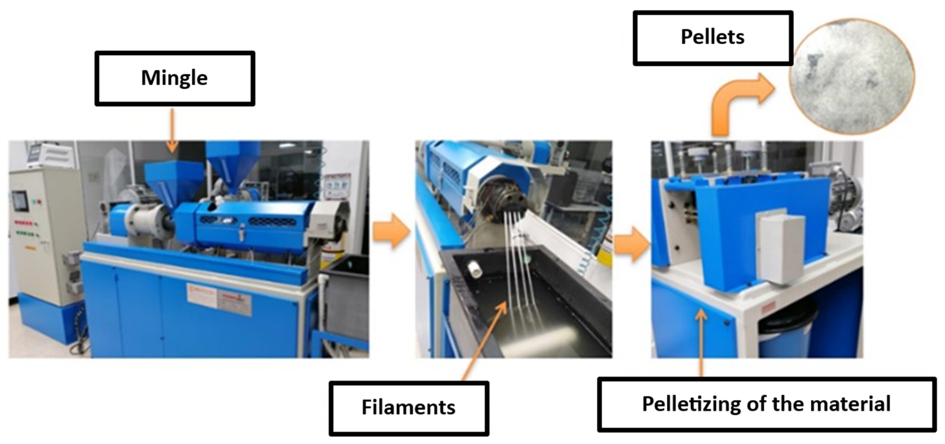
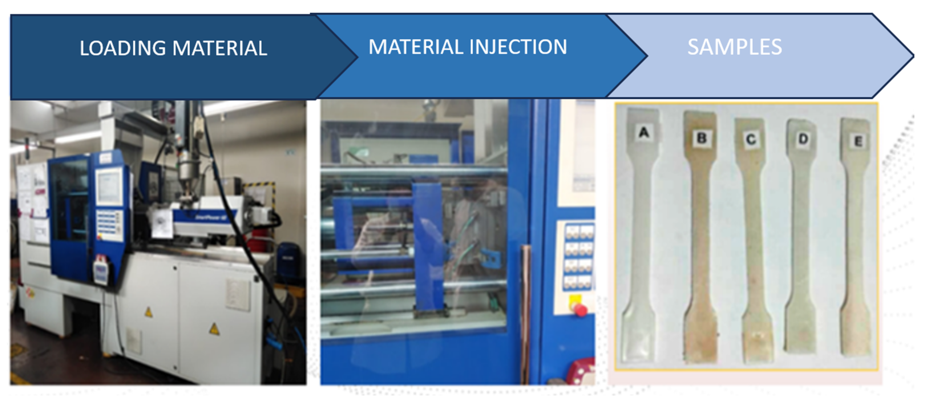
2.2. Preparation of Raw Materials
2.3. Material Characterization
3. Results
3.1. Electrospinning Process
3.2. Characterization of Developed Materials
4. Discussion
5. Conclusions
Author Contributions
Funding
Institutional Review Board Statement
Data Availability Statement
Conflicts of Interest
References
- Laycock, B.; Nikolić, M.; Colwell, J.M.; Gauthier, E.; Halley, P.; Bottle, S.; George, G. Lifetime prediction of biodegradable polymers. Prog. Polym. Sci. 2017, 71, 144–189. [Google Scholar] [CrossRef]
- Langley, J.; Turner, N.; Yoxall, A. Attributes of packaging and influences on waste. Packag. Technol. Sci. 2011, 24, 161–175. [Google Scholar] [CrossRef]
- Kibirkštis, E.; Mayik, V.; Zatserkovna, R.; Vaitasius, K.; Stepanenko, A.; Kandrotaitė-Janutienė, R.; Venytė, I.; Danilovas, P.P. Study of physical and mechanical properties of partially biodegradable LDPE polymeric films and their application for printing and packaging. Polym. Test. 2022, 112, 107646. [Google Scholar] [CrossRef]
- Yuvaraj, G.; Ramesh, M.; Rajeshkumar, L. Carbon and Cellulose-Based Nanoparticle-Reinforced Polymer Nanocomposites: A Critical Review. Nanomaterials 2023, 13, 1803. [Google Scholar] [CrossRef]
- Khan, T.; Sultan, M.T.B.H.; Ariffin, A.H. The challenges of natural fiber in manufacturing, material selection, and technology application: A review. J. Reinf. Plast. Compos. 2018, 37, 770–779. [Google Scholar] [CrossRef]
- Verma, D.; Goh, K.L. Natural fiber-reinforced polymer composites: Application in marine environments. In Biomass, Biopolymer-Based Materials, and Bioenergy; Construction, Biomedical, and other Industrial Applications; Woodhead Publishing: Sawston, UK, 2019; pp. 51–73. [Google Scholar] [CrossRef]
- Amjad, A.; Rahman, A.A.A.; Awais, H.; Abidin, M.S.Z.; Khan, J. A review investigating the influence of nano-filler addition on the mechanical, thermal and water absorption properties of cellulosic fibre reinforced polymer composite. J. Ind. Text. 2022, 51, 65S–100S. [Google Scholar] [CrossRef]
- Kong, C.; Lee, H.; Park, H. Design and manufacturing of automobile hood using natural composite structure. Compos. B Eng. 2016, 91, 18–26. [Google Scholar] [CrossRef]
- Radoor, S.; Karayil, J.; Rangappa, S.M.; Siengchin, S.; Parameswaranpillai, J. A review on the extraction of pineapple, sisal and abaca fibers and their use as reinforcement in polymer matrix. eXPRESS Polym. Lett. 2020, 14, 309–335. [Google Scholar] [CrossRef]
- Pelissari, F.M.; Andrade-Mahecha, M.M.; Sobral, P.J.D.A.; Menegalli, F.C. Nanocomposites based on banana starch reinforced with cellulose nanofibers isolated from banana peels. J. Colloid. Interface. Sci. 2017, 505, 154–167. [Google Scholar] [CrossRef] [PubMed]
- Rashid, A.B.; Haque, M.; Islam, S.M.M.; Labib, K.M.R.U. Nanotechnology-enhanced fiber-reinforced polymer composites: Recent advancements on processing techniques and applications. Heliyon 2024, 10, e24692. [Google Scholar] [CrossRef] [PubMed]
- Zhang, X.; Wang, Y.; Gao, Z.; Mao, X.; Cheng, J.; Huang, L.; Tang, J. Advances in wound dressing based on electrospinning nanofibers. J. Appl. Polym. Sci. 2024, 141, e54746. [Google Scholar] [CrossRef]
- Ochica, A.F.; Muñoz Prieto, E.D.J.; Vera Graziano, R.; Gómez Pachón, E.Y.; Cerda, A.M.; Rivera Torres, F. Obtention of Cellulose Acetate nanofiberes from Sugar Cane Bagasse. Cienc. En. Desarro. 2024, 8, 69–77. Available online: http://www.scielo.org.co/scielo.php?script=sci_arttext&pid=S0121-74882017000200069 (accessed on 12 February 2024).
- Teixeira, E.D.M.; Lotti, C.; Corrêa, A.C.; Teodoro, K.B.R.; Marconcini, J.M.; Mattoso, L.H.C. Thermoplastic corn starch reinforced with cotton cellulose nanofibers. J. Appl. Polym. Sci. 2011, 120, 2428–2433. [Google Scholar] [CrossRef]
- Sandoval, P.R.; Silva, S.M.C. Caracterización de las propiedades mecánicas de un material biodegradable a partir de los procesos de extrusión y peletizado. Inf. Técnico 2017, 81, 177–180. [Google Scholar]
- Sandoval, P.R.; Prieto, E.M.; Pachón, Y.E.G. Obtención y caracterización de un biodegradable a partir de almidón de papa y polietileno de baja densidad por inyección. Inf. Técnico 2015, 79, 61. Available online: https://www.proquest.com/openview/73641a9e12dc0b897191758e5b7d4677/1?pq-origsite=gscholar&cbl=2043241 (accessed on 12 February 2024).
- Singh, S.; Gamlath, S.; Wakeling, L. Nutritional aspects of food extrusion: A review. Int. J. Food Sci. Technol. 2007, 42, 916–929. [Google Scholar] [CrossRef]
- Seghar, S.; Asaro, L.; Rolland-Monnet, M.; Hocine, N.A. Thermo-mechanical devulcanization and recycling of rubber industry waste. Resour. Conserv. Recycl. 2019, 144, 180–186. [Google Scholar] [CrossRef]
- Palange, C.; Johns, M.A.; Scurr, D.J.; Phipps, J.S.; Eichhorn, S.J. The effect of the dispersion of microfibrillated cellulose on the mechanical properties of melt-compounded polypropylene–polyethylene copolymer. Cellulose 2019, 26, 9645–9659. [Google Scholar] [CrossRef]
- ASTM D-638; Standard Test Method for Tensile Properties of Plastics. ASTM: West Conshohocken, PA, USA, 2022.
- ASTM D 2240; Standard Test Method for Rubber Property—Durometer Hardness. ASTM: West Conshohocken, PA, USA, 2021.
- ASTM D 1238; Standard Test Method for Melt Flow Rates of Thermoplastics by Extrusion Plastometer. ASTM: West Conshohocken, PA, USA, 2013.
- Syed, N.; Feng, Y.; Mahar, F.K.; Fahad, R.; Abro, Z.A.; Huang, J. Facile synthesize of composite for pollutant removal of lead and methylene blue (MB). Env. Prog. Sustain. Energy 2024, 43, e14317. [Google Scholar] [CrossRef]
- Saraswat, P.; Singh, B. Utilization of recycled concrete aggregates in LDPE-bonded cementless paver blocks. Constr. Build. Mater. 2024, 419, 135467. [Google Scholar] [CrossRef]


| Parameters | Values |
|---|---|
| Solution flow rate | 30 mL/hra |
| Voltage | 17 kV |
| Distance between needle and collector | 30 cm |
| Volume | 5 mL |
| Polymer concentration | 6% |
| Treatments | |||
|---|---|---|---|
| T | Mixtures (%) | ||
| LDPE | PS | MFCA | |
| T1 | 84.95 | 15 | 0.05 |
| T2 | 84.85 | 15 | 0.15 |
| T3 | 84.7 | 15 | 0.30 |
| T4 | 85 | 15 | 0.00 |
| Process Parameters: Extrusion/Pelletizing | |
|---|---|
| Temperatures | Zone 1: 50 °C |
| Zone 2: 80 °C | |
| Zone 3: 100 °C | |
| Zone 4: 140 °C | |
| Zone 5: 165 °C | |
| Cooling Tank Temperature | 10 °C |
| Extruder Screw Speed | 30 RPM |
| Pelletizer Speed | 40 RPM |
| Extruder Motor Frequency | 50 Hz |
| Pelletizer Motor Frequency | 60 Hz |
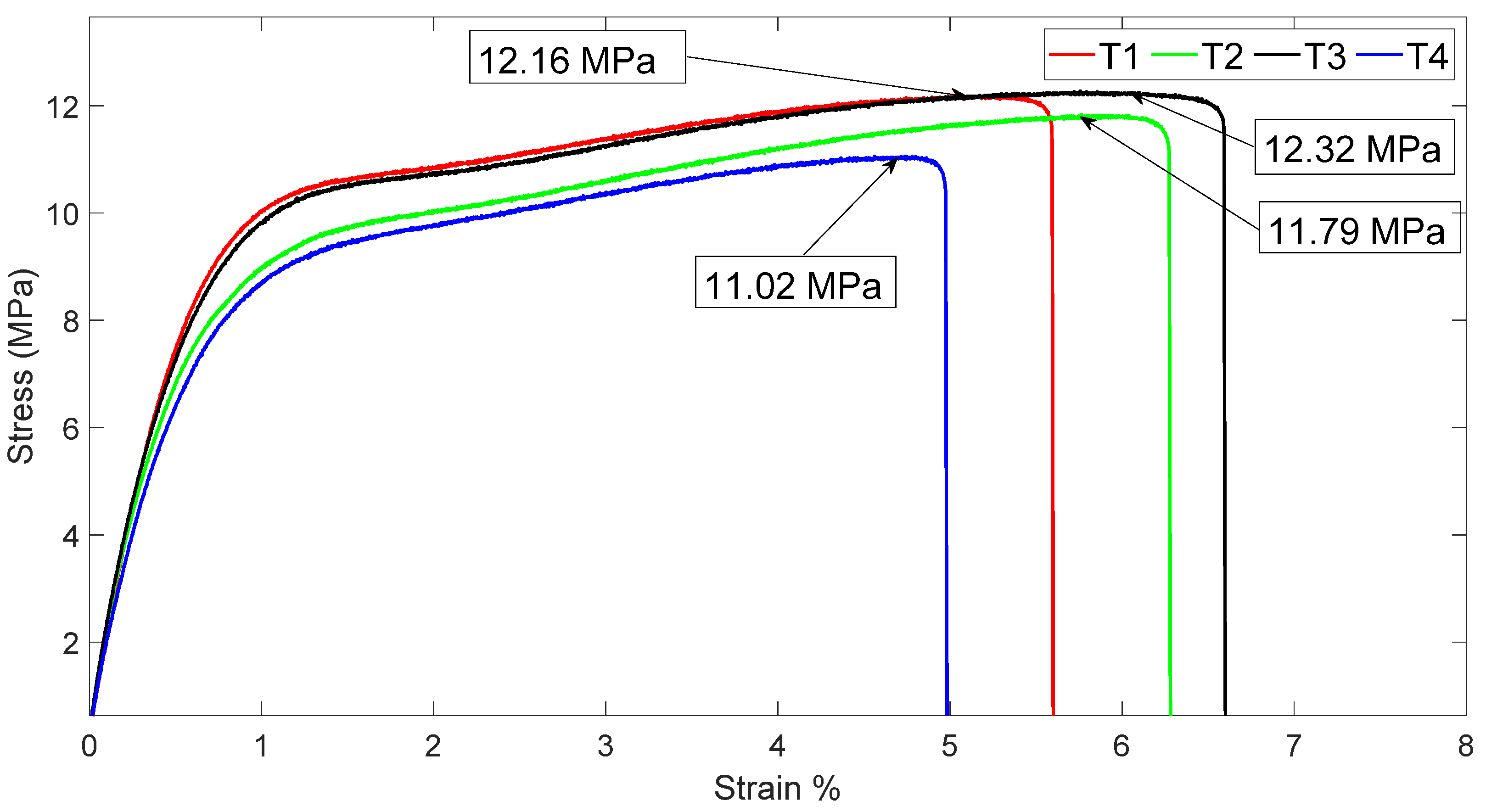
| Treatment | Ultimate Strength |
|---|---|
| T1 (LDPE 84.95%, PS 15%, MFCA 0.05%) | 12.16 ± 0.8 MPa |
| T2 (LDPE 84.85%, PS 15%, MFCA 0.15%) | 11.79 ± 0.3 MPa |
| T3 (LDPE 84.7%, PS 15%, MFCA 0.30%) | 12.32 ± 0.5 MPa |
| T4 (LDPE 85%, PS 15%, MFCA 0.00%) | 11.02 ± 0.2 MPa |
| Treatment Identification | Average Melt Flow Index (g/10 min) |
|---|---|
| T1 | 1.69 ± 0.01 |
| T2 | 1.91 ± 0.13 |
| T3 | 1.55 ± 0.08 |
| T4 | 1.95 ± 0.09 |
Disclaimer/Publisher’s Note: The statements, opinions and data contained in all publications are solely those of the individual author(s) and contributor(s) and not of MDPI and/or the editor(s). MDPI and/or the editor(s) disclaim responsibility for any injury to people or property resulting from any ideas, methods, instructions or products referred to in the content. |
© 2024 by the authors. Licensee MDPI, Basel, Switzerland. This article is an open access article distributed under the terms and conditions of the Creative Commons Attribution (CC BY) license (https://creativecommons.org/licenses/by/4.0/).
Share and Cite
Rodríguez Sandoval, P.; Rubiano-Navarrete, A.F.; Gómez-Pachón, E.Y.; Vera-Graziano, R. Evaluation of Mechanical Properties of Composite Material with a Thermoplastic Matrix Reinforced with Cellulose Acetate Microfibers. Polymers 2024, 16, 2557. https://doi.org/10.3390/polym16182557
Rodríguez Sandoval P, Rubiano-Navarrete AF, Gómez-Pachón EY, Vera-Graziano R. Evaluation of Mechanical Properties of Composite Material with a Thermoplastic Matrix Reinforced with Cellulose Acetate Microfibers. Polymers. 2024; 16(18):2557. https://doi.org/10.3390/polym16182557
Chicago/Turabian StyleRodríguez Sandoval, Pedro, Andres Felipe Rubiano-Navarrete, Edwin Yesid Gómez-Pachón, and Ricardo Vera-Graziano. 2024. "Evaluation of Mechanical Properties of Composite Material with a Thermoplastic Matrix Reinforced with Cellulose Acetate Microfibers" Polymers 16, no. 18: 2557. https://doi.org/10.3390/polym16182557