Article

An Evaluation and Reduction Approach for the Ground Vibration Induced by High Dam Flood Discharge

1
State Key Laboratory of Hydraulic Engineering Intelligent Construction and Operation, Tianjin University, Tianjin 300072, China
2
School of Civil Engineering, Tianjin University, Tianjin 300072, China
3
Institute of Ocean Energy and Intelligent Construction, Tianjin University of Technology, Tianjin 300382, China
4
Ertan Hydropower Plant, Yalong River Hydropower Development Company, Ltd., Panzhihua 617000, China
*
Author to whom correspondence should be addressed.
Water 2024, 16(11), 1559; https://doi.org/10.3390/w16111559
Submission received: 27 April 2024 / Revised: 23 May 2024 / Accepted: 27 May 2024 / Published: 29 May 2024

Abstract

:
Ground vibration induced by high dam flood discharge has been reported to cause severe structure safety threats and environmental issues. In this paper, an evaluation and reduction approach for ground vibration using systematic and comprehensive studies is proposed. Based on the results of hydraulic physical model tests, the hydrodynamic excitation on the stilling basin plate (SBP) is analytically expressed as spatially variable harmonic loads by the three-dimensional least squares method. Afterwards, a theoretical model for the SBP–foundation coupled system is established and the vibration of SBP subjected to analytical hydrodynamic load input is calculated. The ground vibration is further evaluated through the numerical simulation regarding the SBP vibration as the input load. According to the prototype test result, it is found that the variation trend of evaluation results under different working conditions is consistent with the actual situation, which indicates the effectiveness of this evaluation approach. Furthermore, the sensitivity analysis of SBP physical dimensions to ground vibration is conducted, and an optimized design for SBP is presented as a result. The verification results indicate that ground vibration can be significantly reduced by applying SBP optimization.

1. Introduction

With a growing number of hydropower projects with high dams and large reservoirs being put into operation, the velocity of the flow discharged from the discharge structure has exceeded 50 m/s. Strong fluctuating pressures on the surfaces of hydraulic structures can be generated by high-velocity flow, and severe structural vibrations can be consequently induced, which has attracted a lot of attention from researchers and engineers [1,2,3]. However, in recent years, it has been found that the range of vibration extends from local hydraulic structures to surrounding ground and buildings during the flood discharge process of some hydropower projects [4,5,6,7]. To the authors’ knowledge, Kotlyakov et al. [4] publicly reported the phenomenon of surrounding ground vibration induced by high dam flood discharge according to the prototype monitoring data of the Zhigulevskaya Hydropower Project for the first time in 2007. In 2012, the ground vibration issue was found again in the surrounding area of Xiangjiaba Hydropower Station (XHS). Because XHS is located only 1.5 km away from a residential area (Shuifu County), this engineering issue has raised concerns about structural safety risks and environmental problems, additionally, it may threaten the physical and mental health of neighboring residents [8,9]. Therefore, there is an urgent need for the investigation of the generation mechanism, intensity evaluation, and reduction approach of ground vibration induced by flood discharge.
As for the mechanism of ground vibrations, there are several studies on ground vibration induced by excitations such as seismic effect [10], railway [11], pile driving [12], etc., but research into the mechanism of ground vibration induced by flood discharge is still in the initial stage. Based on the results of prototype monitoring, researchers [7] have summarized that this type of ground vibration is a continuous stationary random dynamic response characterized by low frequency, small amplitude, shock characteristics, and long-distance propagation. Moreover, it is concluded that this ground vibration is influenced by factors such as flow rate, discharge scheme, propagation distance, geological conditions, upstream and downstream water levels and flow patterns in the stilling pool [13,14]. The research results [13,15,16] consistently indicate that the flow fluctuating pressures acting on different flood discharge and energy dissipation structures, including orifices, stilling basin plates (SBP), guide walls, fall-sills, and tail-weirs, are the main cause of ground vibration, but the contribution of the fluctuating loads at different locations to ground vibration is considered to vary. Yin et al. [15] conducted feedback analyses based on the in-situ vibration monitoring data of the XHS project using the finite element method and concluded that the surrounding ground vibration is mainly caused by the vibrations of SBPs. Concluded from comprehensive analyses of the results from hydro-elastic experiments, numerical simulations and innovative signal processing, Lian et al. [16] and Zhang et al. [13] stated that the vibrations of SBPs are the second most contribution, while the contribution from the pressure on orifice surfaces is the most prominent. It is indicated that although which structure contributes the most to ground vibration is still controversial, the contribution of SBPs is definitely one of the most prominent, which is also in line with the intuitive experience of engineering because the dissipation of the significant energy generated by flood discharging mainly occurs in the stilling basin and the contact area between SBP and turbulent flow is much larger than other hydraulic structures. Therefore, the fluctuating pressures acting on SBPs need to be further investigated for a better evaluation of ground vibration from the perspective of dynamic inputs.
Essentially, ground vibration is the output of a complex dynamic coupling system (containing hydraulic structures, the foundation and the surrounding ground) subjected to hydrodynamic loads generated by flood discharge. It is noted that the analyses of the fluid–structure coupling effect between hydrodynamic loads and hydraulic structures, the interaction between hydraulic structures and the foundation, and the vibration propagation in the complex site are all extremely challenging, hence there is very little theoretical research on the generation mechanism of this type of ground vibration. As for the fluid–structure coupling effect, in engineering practice, the effect of hydraulic structure vibration (i.e., the micro-amplitude vibration of massive, reinforced concrete structures) on hydrodynamic loads can be neglected, thus the fluctuating pressure measured from the hydraulic model test can be used as the input for the aforementioned coupling system. A common research method for studying flow excitations is the establishment of a physical model to simulate the flow conditions and measure the fluctuating pressure acting on different structures [17,18,19]. As for the interaction between a hydraulic structure and its foundation, it is considered that the interaction should be studied in detail and then decoupled from the coupling system in order to quantitatively evaluate the effect of structural dynamic characteristics on system output and reduce ground vibration by the optimization design of the hydraulic structure. Among the hydraulic structures, the stilling basin plate (SBP) is considered in the subsequent analysis for the following reasons: firstly, as mentioned above, the SBP is one of the primary sources of ground vibration (if not the primary one) in different researches [13,15,16], thus improving the SBP can be expected to significantly reduce ground vibration; secondly, the SBP in the actual stilling basin has a certain distribution, which can be modified in its design; thirdly, the SBP is plate-like, of which the dynamic response can be analyzed by referring to existing plate-foundation theory. Specifically, there are several theoretical foundation models and analytic methods proposed for the plate-foundation theory in previous studies, such as the Winkler model [20], Filonenko-Borodich model [21], Pasternak model [22], Hetényi model [23], etc. These foundation models have different emphases on the simulation of ground mechanical characteristics, but for ground vibration induced by flood discharge, the two-parameter foundation models which take the shear force into account (such as the Pasternak model) can better simulate the propagation characteristics of ground vibration.
Existing studies on the evaluation and reduction in ground vibration mainly focus on describing the relationship between flow fluctuating pressure and ground dynamic response through the combination of hydraulic model tests and prototype observation. Zhang et al. [24] investigated the relationship between point fluctuating pressure and discharge, and then proposed a correlation formula between discharge and near-field acceleration. Another reference [14] proposed a method to calculate area fluctuating pressure from point fluctuating pressures, and further obtained the excitation–response correlation for the prediction of ground vibration velocity. Aiming at minimizing ground vibration and satisfying the flood discharge requirement in the meantime, researchers presented an optimal flood discharge scheme based on numerical simulation [15], hydraulic model tests [25] and hydro-elastic model tests [9]. It is noted that although the above studies focused on different aspects, the evaluation and reduction methods based on the influence of structural characteristics on ground vibration are still insufficient. Moreover, the mechanism of ground vibration is believed to be better analyzed by a comprehensive study combining prototype observations, experimental methods, theoretical methods and numerical simulation.
In this paper, the evaluation and reduction in ground vibrations are investigated by analyzing the dynamic response of the SBP under discharge flow excitations. Firstly, through hydraulic physical model tests, the flow excitations in the stilling basin were acquired. Accordingly, the root-mean-squares (RMSs) of flow excitations are fitted and analytically expressed by applying the least squares method (LSM), and the fitting effect is verified. Secondly, based on engineering practice, each SBP is treated as a rectangular plate with free boundaries resting on the foundation, thereupon the theoretical model of the SBP–foundation coupled system is established, in which the SBP is considered as a Kirchhoff plate and the foundation is considered as an elastic Pasternak foundation. The evaluation approach for ground vibration is consequently proposed based on the research results of model tests, theoretical analyses, and numerical simulations, and the approach is verified according to prototype test data. Finally, investigations into vibration reduction through SBP optimizations are carried out based on the above theories, with an optimized design for SBPs given. The results show that the SBP optimization is effective and practical. This study may benefit ground vibration reduction in hydraulic engineering practices.

2. Measurement and Processing of Hydrodynamic Loads

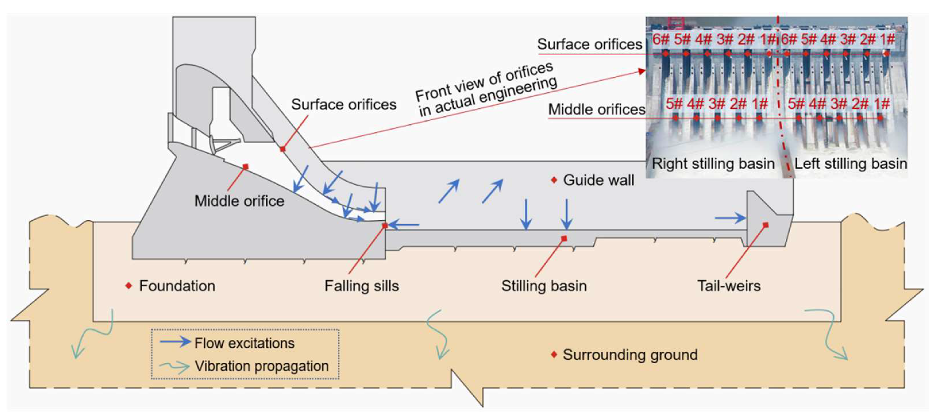
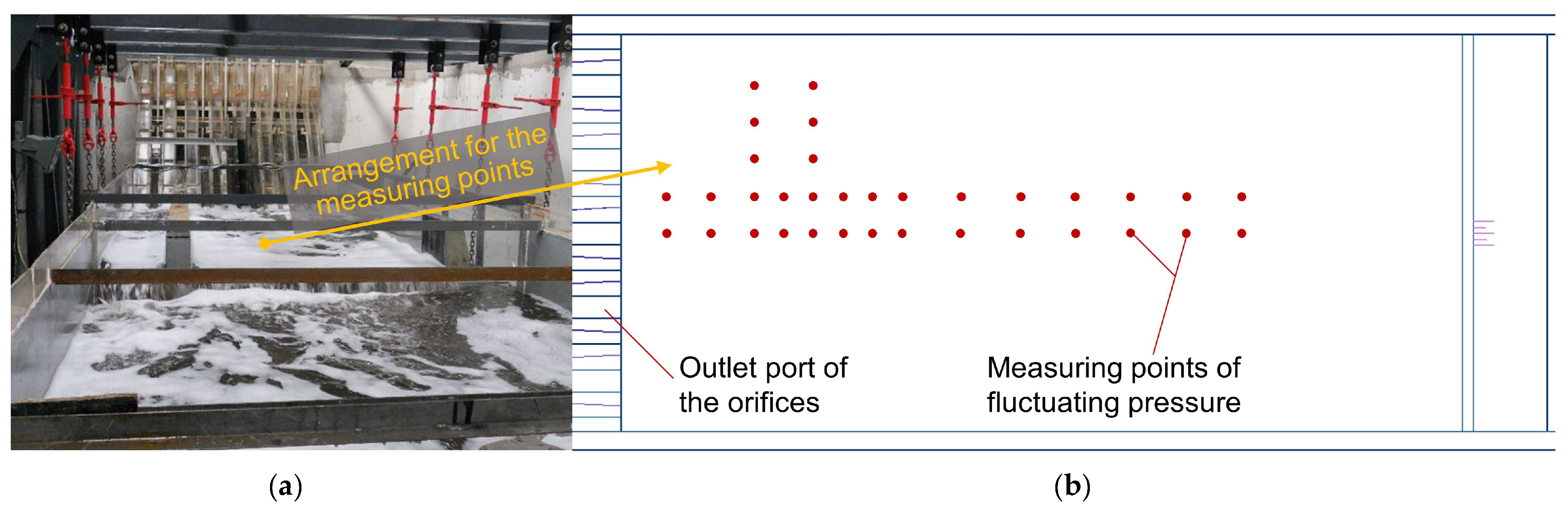
2.1. Measurement of the Hydrodynamic Load in the Stilling Basin

Among the hydropower projects affected by ground vibration issues, the XHS project has the most publicly available research results and engineering information. Consequently, this project is chosen as the research object of this paper. Located in the Jinsha River basin in China, the XHS project is now the fifth-largest hydropower station in China. The dam of XHS is a concrete gravity dam with a maximum height of 162 m. The normal water level of its reservoir is 380 m, with a storage capacity of 5 × 10⁹ m3 and a designed discharge volume of 41,200 m3/s. The discharge structures consist of 12 surface orifices and 10 middle orifices, which are arranged at intervals and are divided into two symmetrical energy dissipation zones by the middle guide wall. During the first flood discharge in October 2012, significant ground vibrations occurred in Shuifu County, which is 1.5 km downstream of the damsite on the right bank. As shown in Figure 1, the cross-section of the gravity dam of XHS and the action position of the flow excitation are illustrated. Yin et al. [15] stated that SBP vibration induced by flood discharge is the main source of ground vibration, which is consistent with the empirical understanding due to the intense turbulence in the stilling basin during flood discharge and the largest action area of flow excitation acting on the SBP. Although this result is controversial, it is believed that SBP vibration is one of the most important sources of ground vibration (if not the primary one). Therefore, studying and optimizing SBPs can not only effectively reduce ground vibration, but also significantly simplify the related analysis and calculation due to its simple geometric shape and the theoretical model for plates on elastic foundation.
The impact of discharged floods on hydraulic structures can be quantitatively described by fluctuating pressure, which can be measured in hydraulic model tests. Generally, silicon piezo-resistive sensors (with 0.01 kPa precision and 200 Hz acquisition frequency) are utilized to obtain the fluctuating pressure data in hydraulic model tests. As shown in Figure 2a, a hydraulic model with a geometric scale of 1:80 was built for the XHS project including the surface and middle orifices, the spillways, the left stilling basin and the guide walls. The selection of the model material should satisfy the law of similarity, and in order to avoid measurement errors, the model material should not generate large vibrations under the flow impact, thus the model material should have sufficient strength. In view of the above characteristics, plastic plates and organic glass are the most commonly used materials for hydraulic models [26]. Among the structures, the fluctuating pressures on the stilling basin bottom are prominent, and accordingly, the material of the stilling basin bottom needs an increased thickness. Moreover, the stilling basin bottom does not need to aid the observation of the flow pattern. Therefore, the non-transparent plastic plates were selected to make the stilling basin bottom for economic considerations. For the other structures, due to the need for flow observation, transparent materials should be selected, thus organic glass is selected to make other structures. As the arrangement of the discharge structure is symmetrical, the measuring points for fluctuating pressure were arranged in the left half of the SBP, and the arrangement of the measuring point was denser in the flow impact area; this is the common practice in hydraulic model tests [14,24]. Under symmetrical discharge conditions, the flow pattern and the fluctuating pressure distribution in the left half of the stilling basin are exactly the same as those in the right half. When the gates are opened asymmetrically, the fluctuating pressure on both halves of the stilling basin can always be obtained by means of experiments under the original and symmetrical discharge conditions.

2.2. Three-Dimensional Least Squares Fitting

As the fluctuating pressure generated by discharged flood is a random load with strong spatiotemporal variability, its intensity characteristics are generally described by the root-mean-square (RMS), of which the distribution on SBPs at a certain moment is a three-dimensional function. Moreover, time variability can be approximated by considering pressure time history as a harmonic wave, for which the frequency is equivalent to the dominant frequency of the original random load. Therefore, based on the results of hydraulic model tests, the water flow excitation at different positions on the SBP can be fitted as a harmonic wave with a specific frequency and RMS.
The least square method (LSM) is frequently used to fit sampled data; the basis of its theory is the minimum square variance between sampled data and fitted values. Suppose that the relation between the flow excitation RMS and coordinates ( x i ,   y i ) can be expressed by the following polynomial:
f x i , y i = a 00 + a 10 x i + a 01 y i + a 20 x i 2 + a 11 x i y i + a 02 y i 2 + + a p 0 x i p + + a p q , q x i p q y i q + + a 0 p y i p p ,   q = 0 ,   1 ,   2 ,   3 ;   0 < q < p
where a denotes the coefficient of the corresponding term, with the two numbers of the subscript denoting the degree of x i and y i , respectively; p denotes the degree of the polynomial; q denotes the degree of y i at a certain term. Given the sampled data ( x i , y i , z i ) , in order to minimize the square variance, the following equation should be satisfied:
B a = Z
where a denotes the vector consisting of all the coefficients of the fitting polynomial; B denotes the Vandermonde matrix, which consists of the coefficients of the coefficient vector in LSM; Z denotes the vector that satisfies the minimum square variance. Thus, the coefficient vector a can be numerically solved.

2.3. Analytical Expression of Hydrodynamic Loads

Based on the experimental results and preliminary calculations, the spatial distribution of fluctuating pressure RMS is fitted by the quintic polynomial given as follows:
f x , y = a 00 + a 10 x + a 01 y + + a 50 x 5 + a 41 x 4 y + + a 05 y 5
In order to verify the fitting accuracy of the analytical expression of hydrodynamic loads given in Equation (3), the degree of fitting of six typical discharge schemes in the model tests was calculated based on the measured values, as listed in Table 1. As the R2 values corresponding to the six different working conditions in Table 1 are all close to 1, it is considered that the polynomial fitting functions are sufficiently accurate. Moreover, Figure 3 illustrates the images of the fitted functions under discharge schemes (a) and (c), the detailed information of which is given in Table 1. There are significant peak values in the flow impact area on the SBP due to the greater impact pressure generated by intense turbulence. For scheme (a) that is operated by surface orifices (represented by Figure 3a), due to the strong flow capacity and the full opening of surface orifices, a more prominent peak of fluctuating pressure is generated; while for scheme (c) that is operated by middle orifices (represented by Figure 3b), due to the relatively weak flow capacity and the small opening of middle orifices, the corresponding peak value is also small, and the fluctuating pressure at each position is relatively average. It should be noted that the above phenomena are consistent with the actual engineering situation, which indicates that the proposed fitted analytical expression can simulate the intensity of the fluctuating pressure in the stilling basin well, thereupon serves as the input load for the following structural dynamics analysis.

3. Evaluation Approach for Ground Vibration Based on the SBP–Foundation Coupled System

In Section 2, the analytical expression of hydrodynamic loads at each location of the stilling basin is obtained. Most of the previous studies on ground vibration paid more attention to the evaluation of the influence of hydrodynamic loads on ground vibrations, but this is not sufficient from the perspective of the generation process of ground vibration, because there is a dynamic interaction between the structure and the foundation. Consequently, the change in structural form (such as the distribution of SBPs) may significantly influence ground vibration responses. As mentioned above, the SBP is one of the primary sources of ground vibration [13,15,16]. In this section, by taking the SBP as the research object, an evaluation approach for ground vibration is proposed by establishing the theoretical model of the SBP–foundation coupled system, and the effectiveness of the evaluation method is verified by comparing the numerical simulation and prototype results.

3.1. Theoretical Model of SBP–Foundation Coupled System

3.1.1. Assumptions Applied to the SBP and Foundation

In engineering practice, SBPs are connected to the foundation by anchorage steel bars, with the four edges not constrained by any boundaries. From the perspective of shape, the SBPs are usually plate-shaped cubes that are constructed of reinforced concrete with a high reinforcement rate due to the strong impact of high-speed water flow. Subsequently, a single SBP can be reasonably considered as a free rectangular plate resting on the foundation, thus constituting a conventional plate–foundation coupled system. In order to analyze the dynamic response of the coupled system, it is necessary to make appropriate assumptions about the SBP and the foundation to establish the theoretical model of the system.
For a rectangular plate corresponding to an SBP, the two commonly used assumptions are the Kirchhoff hypothesis (thin plate hypothesis) [27] and the thick plate hypothesis [28]. Compared to the Kirchhoff hypothesis, the thick plate hypothesis additionally considers the influences of shear and extrusion deformations, as well as rotational acceleration, in the analysis of the stress and deformation state of the plate. However, in this study, the above factors can be reasonably ignored for the following reasons: (1) The SBP is constructed on a firm foundation, it is subjected to gradually changing load, and it has a strong shear stiffness due to its high reinforcement ratio, resulting in minimal shear deformation. (2) According to engineering experiences [29], the vertical displacement of an SBP is below 100 μm under most working conditions, which is extremely small compared to the thickness of the SBP, resulting in a very small extrusion deformation. (3) The bending moment and deflection angle of an SBP are very small, and the dominant frequency of excitation is far less than the fundamental frequency of the SBP, so the structural natural vibration mode will not be excited and, consequently, the dynamic effects induced by rotational acceleration on the structure will be insignificant. Moreover, the main objective of this study is to reasonably evaluate the correlation between the geometric shape of the SBP and ground vibration, which places more focus on the practical application of engineering. Therefore, in order to strike a balance between calculation accuracy, computational difficulty, and practicality for potential engineering applications, the Kirchhoff hypothesis is adopted for the SBP.
Another vital aspect of the SBP–foundation coupled system is the selection of an appropriate foundation model. In the XHS project, the foundation of the stilling basin is fresh sandstone with sufficient hardness and continuity. In engineering practice, such a foundation is often represented by the Winkler foundation model [20], which treats the foundation as uniform springs. However, this model only considers the hardness of the foundation without considering its continuity, which is not conducive to the application of the SBP–foundation coupled system in terms of ground vibration evaluation. For this reason, the Pasternak foundation model [22] is adopted, which has two parameters regarding hardness and continuity.
Based on the above assumptions, the theoretical model of the SBP–foundation coupled system can be established. As shown in Figure 4, the theoretical model is illustrated, where the x- and y-coordinates denote the directions across and along the river, respectively. Accordingly, a and b denote the lengths across and along the river, respectively. It is noted that only the vertical dynamic responses are considered below because the SBP is mainly subjected to the hydrodynamic pressure in the normal direction of its horizontal top surface.

3.1.2. Dynamic Analysis of the SBP–Foundation Coupled System

The dynamic equation of the SBP–foundation coupled system is given as follows.
4 w G s D 2 w + m ¯ D 2 w t 2 + K s D w = q D
where 2 is the Laplace operator; w = w x , y , t denotes the time- and spatially-varying deflection of the SBP; q = q x , y , t denotes the time- and spatially-varying hydrodynamic load, i.e., the fluctuating pressure; m ¯ denotes the mass per unit area of the SBP; K s and G s denote the spring and shearing parameters in the Pasternak foundation model, respectively; D denotes the flexural rigidity of the SBP. The expressions of parameters D, K s , and G s are given as follows [30,31]:
D = E h 3 12 1 μ 2
K s = 0.65 E s b 1 μ s 2 E s b 4 E I 1 12
G s = 13 b E s 32 1 + μ s
where E, h and μ denote the elasticity modulus, thickness and Poisson’s ratio of the SBP, respectively; E s and μ s denote the compression modulus and Poisson’s ratio of the foundation, respectively.
In this study, the fluctuating pressure on the surface of the SBP is considered to be the spatially variable harmonic loads, and the harmonic frequencies are equal to the dominant frequencies of the hydrodynamic excitations. It is noted that due to the phase asynchrony among the harmonic loads at different positions on the SBP surface, a point-area conversion factor for fluctuating pressure should be introduced to more realistically reflect the hydrodynamic loads acting on the SBP. According to a large number of experimental data, the conversion factor is believed to be positively correlated to the depth of the water cushion and the turbulence degree, with its value ranging from 0.4 to 1.0 [32]. Because the XHS project has a deep water cushion and a large turbulence degree, the conversion factor of this study is set at 0.8, which is considered to be a reasonable value. Combined with the results in Section 2.3, the flow excitation q = q x , y , t can be expressed as:
q x , y , t = q 0 x , y cos θ t = 0.8 f x , y cos θ t
where θ denotes the dominant frequency of flow excitation.
In engineering practice, the connections between two adjacent SBPs are in a flexible form, such as copper sheet and rubber water stops, and the SBPs are fixed to the foundation by densely distributed steel bars. As there are no constraints at the boundaries and corners of SBP, it should be regarded as a rectangular plate with free boundaries on the foundation. Suppose that at the initial time t = 0, and the displacement and velocity are zero, i.e., w x , y , 0 = w / t = 0 . In order to solve the dynamic equation of the SBP–foundation coupled system, the method of separation of variables is applied. The solution to Equation (4) w x , y , t and the flow excitation q x , y , t can be expressed as follows:
w x , y , t = m = 1 n = 1 W m n x , y T m n t q x , y , t = m = 1 n = 1 W m n x , y F m n t
where W m n x , y denotes the mode shape function; T m n t describes the temporal variability of function w ; F m n t is another time function that is analogous to T m n t ; m and n denote the orders of the modes in x and y directions, respectively. Note that the mode shape function W m n x , y is required to satisfy the boundary conditions of free boundaries [33], thus an expected W m n x , y can be given as follows [34,35]:
W m n x , y = f m n ( φ 1 cos α m x + φ 2 cos β n y cos α m x cos β n y + β n 2 2 μ x 2 + α m 2 2 μ y 2 ) + f 0
where f m n and f 0 are unknown parameters, and the expressions of the coefficients α m , β n , φ 1 and φ 2 are given as follows:
α m = 2 m π a β n = 2 n π b             m , n = 1 , 2 , 3 ,
φ 1 = 1 + a 2 b 2 μ φ 2 = 1 + b 2 a 2 μ
By substituting Equation (9) into Equation (4), the following equation can be obtained.
m = 1 n = 1   4 W m n T m n G s D m = 1 n = 1   2 W m n T m n + m ¯ D m = 1 n = 1 W m n d 2 T m n d t 2 + K s D m = 1 n = 1 W m n T m n = 1 D m = 1 n = 1 W m n F m n
In order to obtain the analytical expression of the time function T m n t , the flow excitation q x , y , t is rewritten as follows:
q x , y , t = q 0 x , y cos θ t = m = 1 n = 1 C m n f m n φ 1 cos α m x + φ 2 cos β n y cos α m x cos β n y + β n 2 2 μ x 2 + α n 2 2 μ y 2 + f 0 cos θ t
Compared with Equation (9), it can be obtained that F m n t = C m n cos θ   t . According to the expansion formula of trigonometric series, C m n can be expressed as follows.
C m n = 0 a 0 b q 0 x , y W m n x , y d x d y 0 a 0 b W m n 2 x , y d x d y
Additionally, by considering the characteristic equation of the mode shape function and the orthogonality of mode shape functions, T m n t can be obtained as follows:
d 2 T m n d t 2 + ω m n 2 T m n = 1 m ¯ C m n cos θ t
where ω m n denotes the natural frequency corresponding to system mode with orders m and n in x and y directions. It is noted that Equation (14) is an ordinary differential equation for T m n t .
By solving Equation (14) and integrating Equation (10), the analytical solution of the vertical displacement response of the SBP under flow excitation can be obtained as:
w x , y , t = m = 1 n = 1 C m n m ¯ ω m n 2 θ 2 cos θ   t cos ω m n t f m n φ 1 cos α m x + φ 2 cos β n y cos α m x cos β n y + β n 2 2 μ x 2 + α m 2 2 μ y 2 + f 0
Correspondingly, the vertical acceleration response of the SBP can be expressed as:
w x , y , t = m = 1 n = 1 C m n m ¯ ω m n 2 θ 2 ω m n 2 cos ω m n t θ 2 cos θ   t f m n φ 1 cos α m x + φ 2 cos β n y cos α m x cos β n y + β n 2 2 μ x 2 + α m 2 2 μ y 2 + f 0
In Equations (15) and (16), the natural frequency of each order, i.e., ω m n , is unknown. In order to obtain ω m n , the Rayleigh–Ritz method is adopted [36]. According to the principle of minimum potential energy, the following formulae can be obtained:
Π m n = U m n V m n = D 2 0 a 0 b 2 W m n 2 2 1 μ 2 W m n x 2 2 W m n y 2 2 W m n x y 2 d x d y + K s m ¯ ω m n 2 2 0 a 0 b W m n 2 d x d y + G s 2 0 a 0 b W m n x 2 + W m n y 2 d x d y = 0
where Π m n denotes the total potential energy for each mode of the system. By substituting the mode shape function (10) into Equation (17) and applying variational principles for coefficients f m n and f 0 , the natural frequency of each order ω m n can be solved. Consequently, the complete analytical solutions for the displacement and acceleration responses of the SBP can be obtained from Equations (15) and (16), respectively.

3.2. Calculation of the Dynamic Response of SBP

In the XHS project, the layout of the SBPs for the single stilling basin on the right side is shown in Figure 5. It is noted that the SBP layouts for the left and right stilling basins are not the same, while the overall physical dimensions of the two stilling basins are identical. Based on the aforementioned theoretical model, analytical solutions can be obtained for the dynamic responses of all SBPs subjected to spatially variable harmonic hydrodynamic loads. According to engineering practice, the dominant frequency of fluctuating pressure (parameter θ ) is determined to be 0.4 Hz. The superposition of 5 × 5 modes (i.e., m = n = 5) is considered in the calculations to ensure the accuracy of the results. The equivalent thickness of the SBP with an irregular shape is considered to be the average thickness of the cross-section. Moreover, the values of the parameters in the theoretical model are obtained from prototype measurements in the XHS project and are listed in Table 2.
Taking the SBP named P1 in Figure 5 as an example, the displacement and acceleration time histories at its centroid are shown in Figure 6. The RMSs of displacement and acceleration are 25.21 μm and 6.53 gal, respectively, and the dominant frequency of displacement time history is 0.405 Hz. Similar to the previous prototype observation results, the forced vibration of the SBP is generated under flow excitation. Due to the absence of sensors embedded during concrete pouring, the vibration of the SBP in the XHS project cannot be effectively measured. The dynamic response measurement of the SBPs in other hydropower projects has been conducted [37,38] and the vibration values and the above calculation results are of the same order of magnitude, but these measurement data cannot be regarded as direct evidence for verifying the validity of the calculation results and theoretical model because there are obvious differences in the flow patterns and structural characteristics among different engineering projects.

3.3. Verification of the Effectiveness of Evaluation Approach

As shown in Figure 7, the numerical model is established by commercial finite element analysis software. The areas with different geological conditions for the surrounding ground are simulated in detail according to the actual conditions for XHS, and the parameter values describing the mechanical performance of different ground areas are derived from engineering geological exploration data, which is shown in Table 3. Moreover, the mesh size of the element is smaller than 1/8 of the wavelength, which equals 25 m according to prototype tests, and the calculation time and time step are set at 200 s and 0.02 s, respectively. Combined with the theoretical model, the acceleration response at the centroid of every SBP is calculated and applied to the corresponding position in the numerical model. It is noted that the infinite element boundary condition [39] is applied around the model in order to simulate the infinite propagation distance of vibration waves and minimize the vibration reflection caused by model boundaries.
The working conditions that the flood discharged into left and right stilling basins by discharge schemes (a) and (c) are given in Table 4 and considered in the numerical simulation, thereafter the vertical accelerations of the verification point named P2 in Figure 7 are computed. Although the data for a length of 200 s are obtained, only the middle section (50 s to 150 s) is analyzed to ensure that the data represent the stable dynamic response under working conditions I to IV. The acceleration time history of point P2 under working condition I is shown in Figure 8.
The reason for conducting the numerical calculation under the aforementioned four working conditions is that the vibration acceleration at the P2 position under these working conditions is obtained by prototype tests, thus it is convenient for comparison and verification. The comparison of the RMS between the calculated and measured accelerations is shown in Figure 9, which indicates that the variation trend of acceleration RMSs obtained from numerical simulations under different working conditions is the same as those RMSs obtained from prototype tests. It is noted that the simulation result values constitute only about half of the measurement values, the reason is that only the contribution of SBP vibration to the dynamic response of the surrounding ground is considered in the calculation, whereas the contribution from other hydraulic structures (such as the orifice, fall-sill, and tail-weir) is not considered. In general, the evaluation approach can reasonably and effectively describe the variation trend of ground vibration under different working conditions. This provides a theoretical basis and technical support for the subsequent research on ground vibration reduction by optimizing SBPs.
It is noted that the discharge schemes for working conditions I and III seem to be the same. The only difference between working conditions I and III is that the flood is discharged into the right and left stilling basins, respectively. As the SBPs of the right stilling basin are generally smaller than those of the left stilling basin, it is considered that the main reason for the greater ground vibration generated under condition I may be that more gaps are arranged between the right SBPs and thus the overall constraint is weaker in the right stilling basin. Moreover, as shown in Figure 7, the verification point P2 is located at the right bank of the dam site, and the location of the right stilling basin is closer to P2 than that of the left stilling basin, thus it can be reasonably inferred that ground vibration under the working condition that the flood discharged into right stilling basin is likely to be stronger. Furthermore, the complex vibration propagation paths may also be one of the reasons why ground vibrations exhibit such differences.
As shown in Figure 9, although the tendencies for the results of the numerical calculations and prototype measurements are similar, there are still obvious differences. The main reasons for the large differences are discussed as follows. Firstly, in consideration of the flow characteristics and structural form of the SBP, only the contribution of the SBP to ground vibration is considered in this study, while the vibration contributions from other positions (such as orifices, guide walls, etc.) are not considered for the reason of complexity. As a result, the calculated results are necessarily smaller than the measured results. Secondly, in order to consider the phase asynchrony among the hydraulic excitations at different positions on the SBP surface, a point-area conversion factor of fluctuating pressure has to be employed [32]. It is noted that errors will probably be introduced by this point-area conversion factor because only the point fluctuating pressure can be measured in hydraulic model experiments while the area load should be applied in the calculation. Thirdly, we consider the time history of hydrodynamic excitation as a harmonic wave, for which the frequency is equivalent to the dominant frequency of the original random load. According to engineering practice, the dominant frequency of fluctuating pressure is always very significant and has slight spatiotemporal variability under stable operating conditions. This simplification operation is also one of the potential sources of errors. Based on the main reasons mentioned above, errors are generated between the numerical calculation and the prototype measurement. However, such errors are actually frequently generated in model experiment research in hydraulic engineering [9,24]. We need to make it clear that the purpose of this study is to investigate the influence of changes in SBP structural form on ground vibration, in other words, this is a trend study. From the perspective of engineering applications, we believe that the evaluation approach is reasonable and effective, because the calculated and measured results of ground vibration are in the same order of magnitude, and the variation trends of both results under different working conditions are consistent with each other.

4. Results and Discussions—Ground Vibration Reduction Based on SBP Optimization

The evaluation approach actually decouples the SBP (as a specific example of hydraulic structures) from the dynamic coupling system containing the hydraulic structure, foundation and surrounding ground, thus we can obtain some insight into the role of the SBP in the system. As for a stilling basin in engineering practice, although its overall size is generally fixed due to safety considerations because the bottom of the stilling basin is composed of multiple SBPs, the distribution of SBPs and the physical dimension of each SBP is convenient to change in the design phase. It can be inferred that the design changes made to SBPs may also have an influence on ground vibration response, which has not been publicly studied to the authors’ knowledge. In this section, based on the evaluation approach in Section 3, the influence of the physical dimensions of SBP on ground vibration reduction is discussed by sensitivity analyses, thereupon the reason for this influence is investigated, with an optimized SBP design proposed.

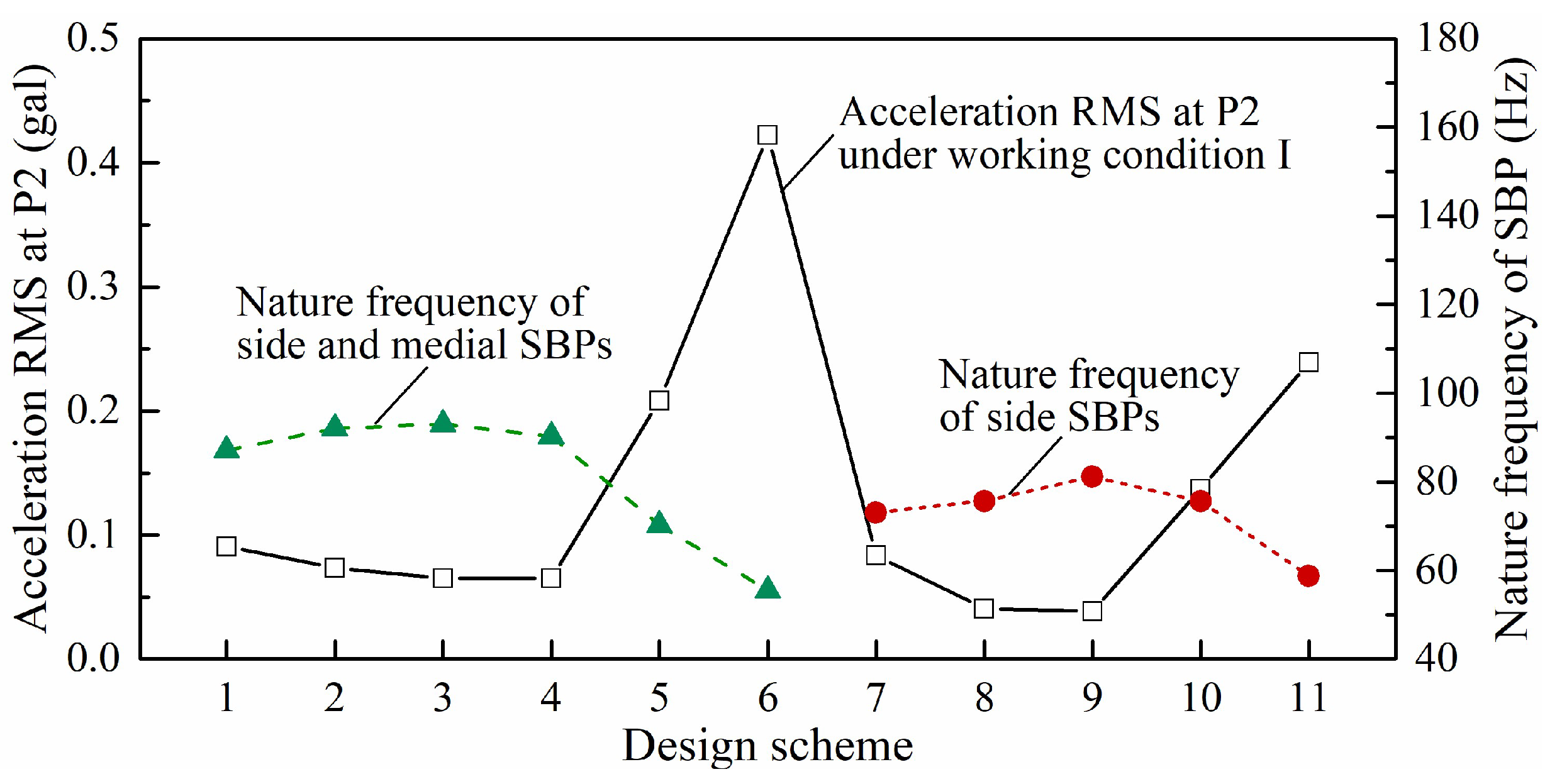
4.1. Sensitivity Analysis for SBP Physical Dimensions to Ground Vibration

Equations (15) and (16) imply that the influencing factors of the dynamic response of SBP include the time and frequency characteristics of flow excitation, the foundation lithology, the physical and mechanical properties of SBP, as well as the physical dimensions of SBP. Therefore, the vibrations of SBP and the surrounding ground can be reduced by optimizing these influencing factors. The time and frequency characteristics of hydrodynamic loads have been optimized by researchers [9,25] by improving the flow pattern in the stilling basin, which attenuates the vibrations to a certain extent. However, ground vibration is still perceptible, especially under working conditions with large volumes of flood discharge. The foundation lithology and mechanical properties of SBP are generally unchangeable, due to the specific construction site of the project and the reinforced concrete materials commonly used in SBP construction. Since adjusting the SBP size is convenient in the design phase, it is a promising method to reduce ground vibration by the SBP size optimization.
As shown in Figure 5, the length (along the river) and width (across the river) of SBP are not uniform in the original design due to the results of anti-floating stability calculations [40]. In this sensitivity analysis, under the fixed total size of the entire stilling basin, only one of the objective parameters (i.e., the length, width or thickness) of SBP is considered at a time, and the corresponding parameters of all the SBPs are uniform for the convenience of analysis. In order to analyze the effect of different design schemes on ground vibrations, based on the evaluation method proposed in Chapter 3, the numerical model in Figure 7 was still employed to calculate the dynamic response at point P2. The input loads for all the calculation conditions are obtained under working condition I in Table 4. Accordingly, the sensitivity analysis of a single SBP physical dimension to ground vibration is carried out. The design schemes and corresponding calculation results of the acceleration RMS are listed in Table 5, where schemes 1–6 are length changes, schemes 7–11 are width changes, schemes 12–16 are thickness changes of equal proportions, and schemes 17–23 are changes in the number of thickened SBP. It is noted that the ground acceleration response listed in Table 5 is so small that the generated vibration seems imperceptible. However, the calculation process only considers the SBP as the vibration source, thus the calculation values are approximately half of the actual vibration as illustrated in Figure 9. In addition, for the stochastic vibration process that approximately satisfies the normal distribution, the RMS values of the dynamic responses are generally 1/3 of the peak values. Moreover, the dynamic amplification effect of buildings on the surrounding ground is very significant, and the vibration amplification coefficients at the top of buildings may exceed 5 depending on the dynamic characteristics of structures [41]. Accordingly, although the variation amplitude of the acceleration RMS in Table 5 is small, the variation of the vibration response can be significant when extended to the actual situation. Therefore, ground vibration reduction based on SBP optimization is of great significance.
In order to intuitively show the calculation results under different schemes, the trends of ground vibrations at P2 under different optimization types are illustrated in Figure 10. Combined with Table 5 and Figure 10, it can be concluded that there is an optimal length and width for the SBP, which is 14.25 m and 15 m, respectively. As for the SBP thickness, ground vibration at position P2 always decreases with the increase in the thickness of SBP, regardless of the changes of equal proportions or the changes in the number of thickened SBPs.

4.2. Discussions on the Ground Vibration Reduction Mechanism Based on SBP Optimization

According to the sensitivity analysis given in Section 4.1, the RMS of ground acceleration can be significantly changed by adjusting the physical dimensions of SBP under identical flow excitation and site conditions. It is proved that the increase in SBP thickness will reduce ground vibration, and there is a length and width that are most conducive to ground vibration reduction. Although the actual generation mechanism of ground vibration is very complicated since the dynamic response of SBP is the only source of ground vibration involved in this study, the reduction in SBP vibration response will lead to a reduction in ground vibration. Therefore, combined with the theoretical model proposed in Section 3, the mechanism of ground vibration reduction through SBP optimization can be further explained.
Since the natural frequencies of SBPs are much higher than the effective frequency components of hydrodynamic excitation (about 0.4 Hz), the SBP only generates forced vibration without resonance effect. Therefore, an increase in the natural frequency of SBP will reduce its dynamic response and thus reduce ground vibration. For the length and width of SBP, optimal values are presented through sensitivity analyses, hence a relatively simple rule can be drawn from Figure 11 by analyzing the correlation between ground vibration and SBP fundamental frequency. As shown in Figure 11, for design schemes 1–6 (length changes), scheme 3 (SBP length 14.25 m) has the largest natural frequency of SBP; for design schemes 7–11 (width changes), scheme 9 (SBP width 15 m) has the largest natural frequency of SBP. It can be concluded that ground vibration basically decreases with the increase in the natural frequency of SBP, thus the SBP length in scheme 3 and the SBP width in scheme 9 are beneficial to ground vibration reduction.
As for the SBP thickness, there are two probable reasons for the vibration reduction caused by the increase in SBP thickness. On the one hand, the increase in SBP thickness will certainly increase its natural vibration frequency and thus reduce the dynamic response. On the other hand, with the increase in SBP thickness, the vertical stiffness of SBP also increases. Since the hydrodynamic load acting on SBP is vertical, the vertical dynamic response will thereupon decrease. Moreover, it can be concluded from Figure 10c,d that when the thickness proportion exceeds 1, the damping effect becomes not obvious; a small increase in the number of thickened SBPs will not significantly reduce the vibration, and only a substantial increase in the number of thickened SBP can significantly improve the vibration reduction effect.

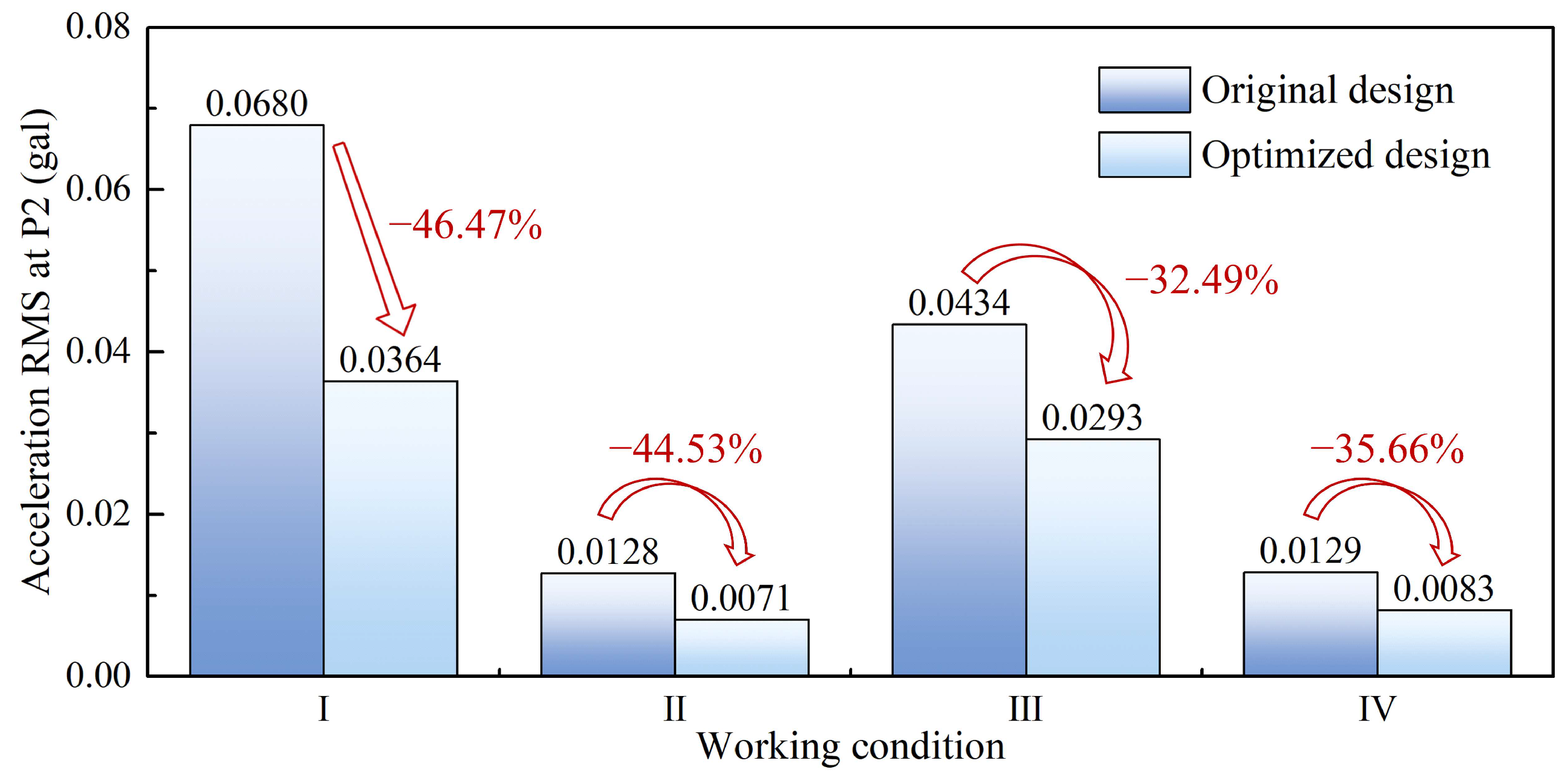
4.3. An Optimized SBP Design and Its Vibration Reduction Effect

Comprehensively considering the results in Section 4.1, an optimized SBP design can be proposed by adopting the optimal length and width simultaneously on every SBP. It is noted that in engineering practice, increasing the SBP thickness will inevitably increase the amount of concrete. Since the ground vibration reduction effect can be significantly improved only when the number of thickened SBP is substantially increased, the SBP thickness is not changed in the optimized design for the balance of economic costs and vibration reduction effect. As shown in Figure 12, ground vibrations are significantly reduced by applying the optimized SBP design, which proves the effectiveness of the proposed vibration reduction approach. Note that although the optimized SBP design is obtained under working condition I, it has a general and effective reduction effect on ground vibration under working conditions I, II, III and IV.
It can be concluded from Figure 12 that SBP optimization has a certain effect on reducing ground vibration. Moreover, compared with other vibration reduction methods, the SBP optimization also has certain advantages. A large number of previous vibration reduction studies were based on the optimization of flood discharge conditions [9,15,25]; however, in the actual operation of a hydraulic engineering project, the discharge condition is determined by the National Power Dispatching Center (NPDC) and always strictly implemented, which restricts the application of the optimized conditions. Other kinds of optimization approaches were based on the signal processing of prototype data [7,16], but due to the complexity of the dynamic process and the interference in prototype tests, the reliability of these approaches still needs to be strengthened. In contrast, the vibration reduction method based on SBP optimization can be realized in the design phase, which only needs to simply modify the size of each SBP without changing the overall size of the entire stilling basin, so that an effective vibration reduction can be achieved with small changes. Therefore, the ground vibration reduction method based on SBP optimization in this paper is more effective and practical.

5. Conclusions

In this paper, an evaluation and reduction approach for ground vibration induced by high dam flood discharge is proposed. Systematic and comprehensive studies are carried out to decouple the stilling basin plate (SBP) from the dynamic coupling system containing a hydraulic structure, foundation and surrounding ground, and the role of SBP in the system is investigated. The main conclusions and results are summarized as follows:
(1)
Based on the hydraulic model tests of Xiangjiaba Hydropower Station (XHS), the spatial distribution for the root-mean-squares (RMSs) of fluctuating pressures acting on the SBPs is obtained and further fitted in the form of polynomials by employing the three-dimensional least squares method. Afterward, the hydrodynamic load is analytically expressed as spatially variable harmonic excitation. As the R2 values corresponding to the data fitting under different working conditions are all close to 1, it is believed that the polynomial fitting functions are sufficiently accurate.
(2)
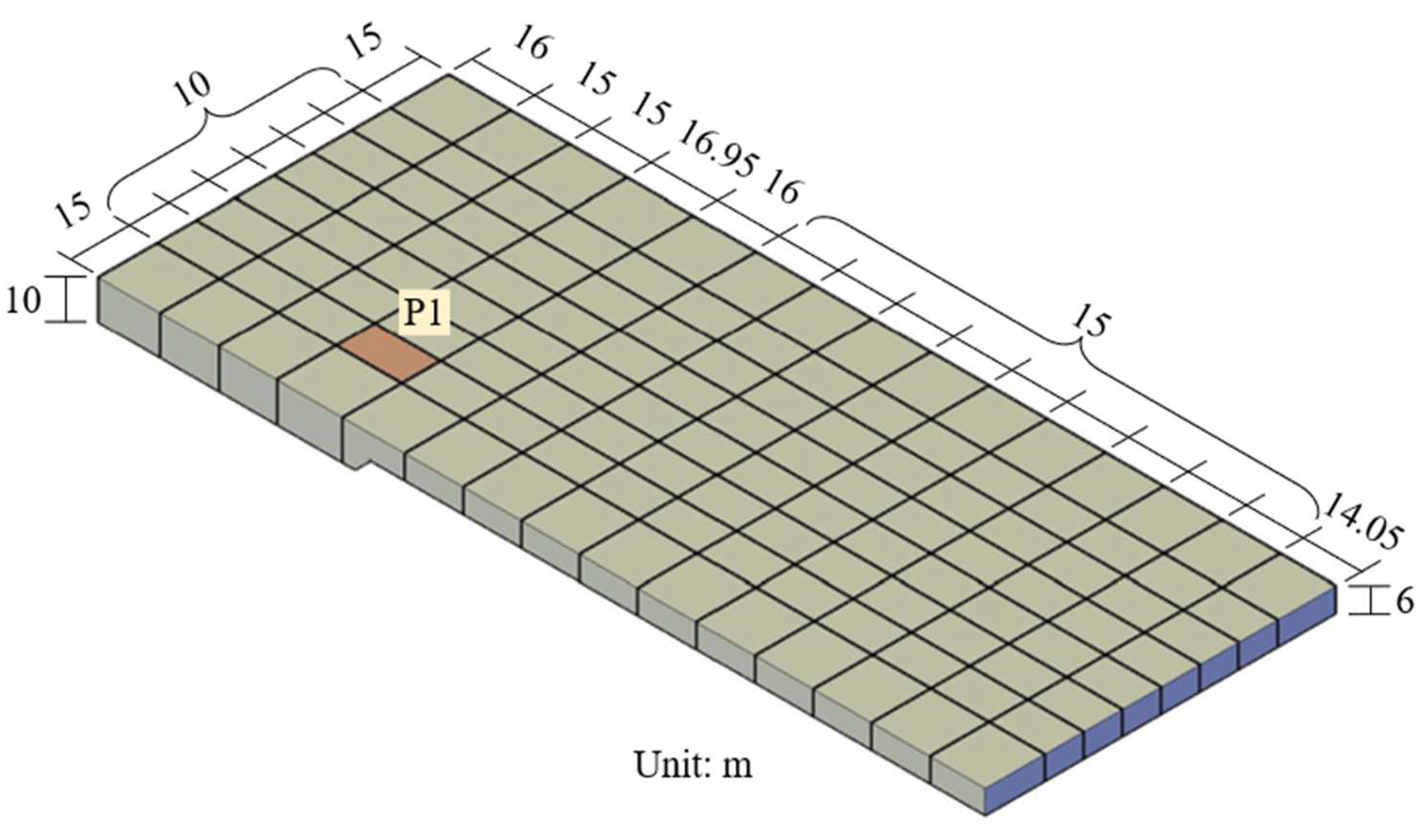
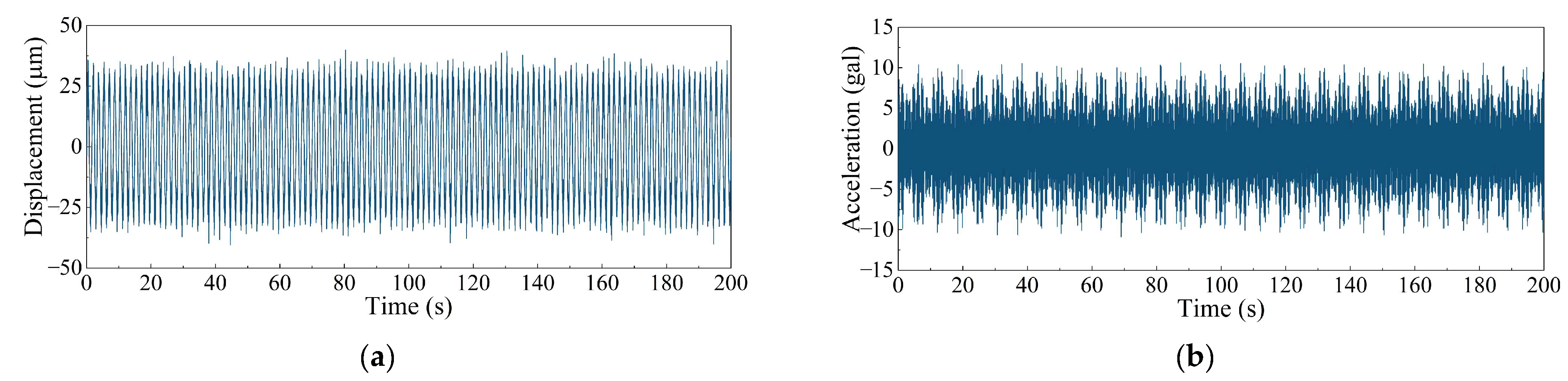
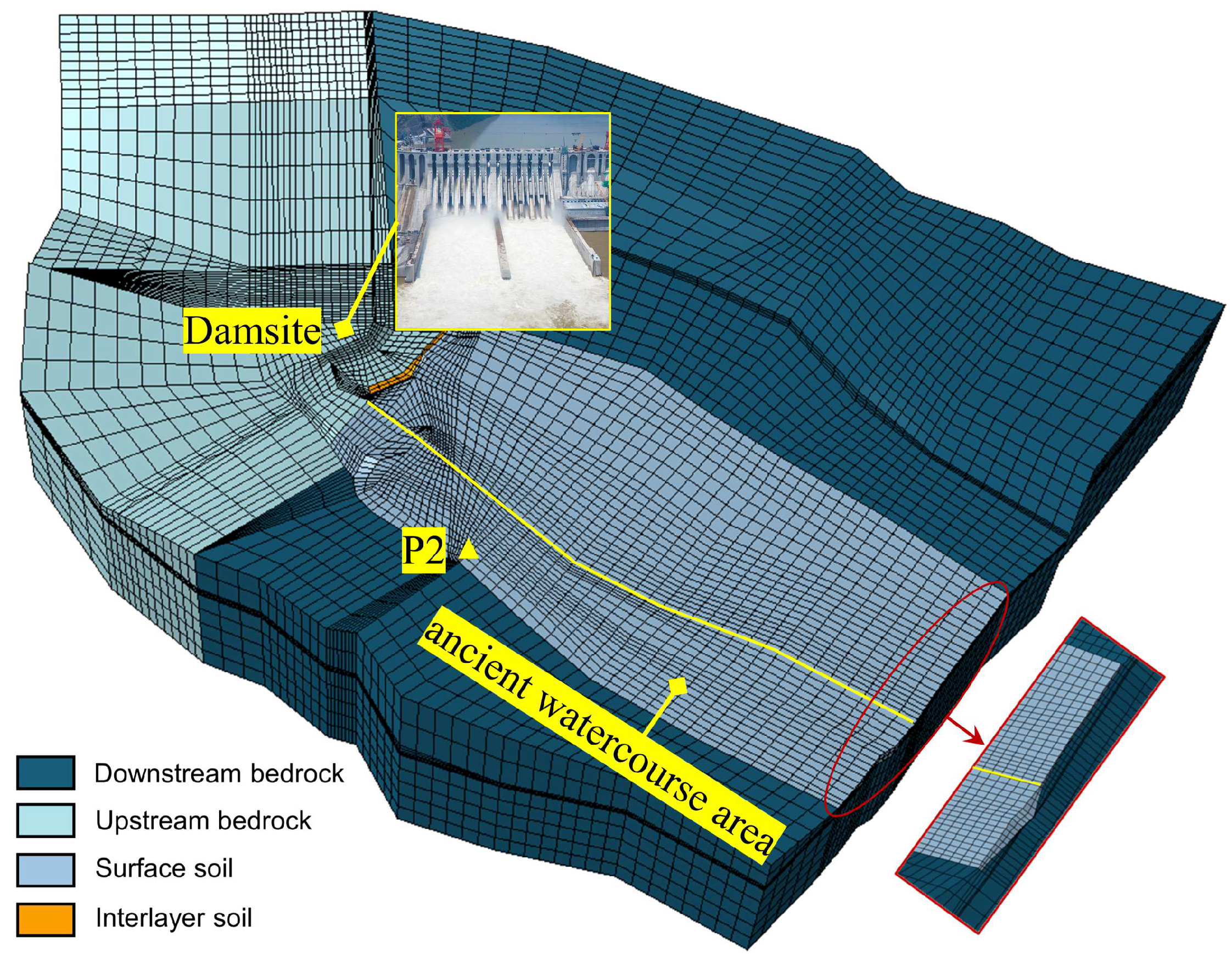
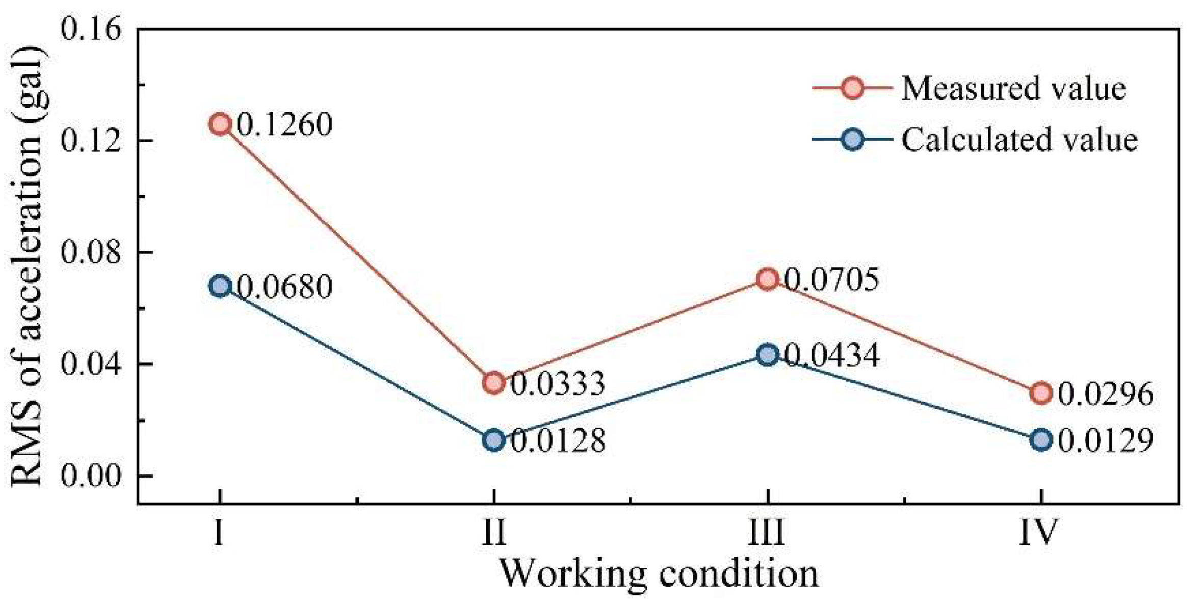
The theoretical model for the SBP–foundation dynamic coupling system is established by considering the SBP as a rectangular plate satisfying the Kirchhoff hypothesis and the SBP as the Pasternak foundation. Thereafter, the dynamic response of SBP is deduced and considered to be the forced vibration under the analytical excitation input. Accordingly, ground vibration is evaluated by applying the acceleration response of every SBP to the corresponding position in the finite element model with infinite element boundary conditions. Compared to some of the available prototype measurement results, the variation trend of evaluation results under different working conditions is consistent with the actual situation, which verifies the effectiveness of the evaluation approach.
(3)
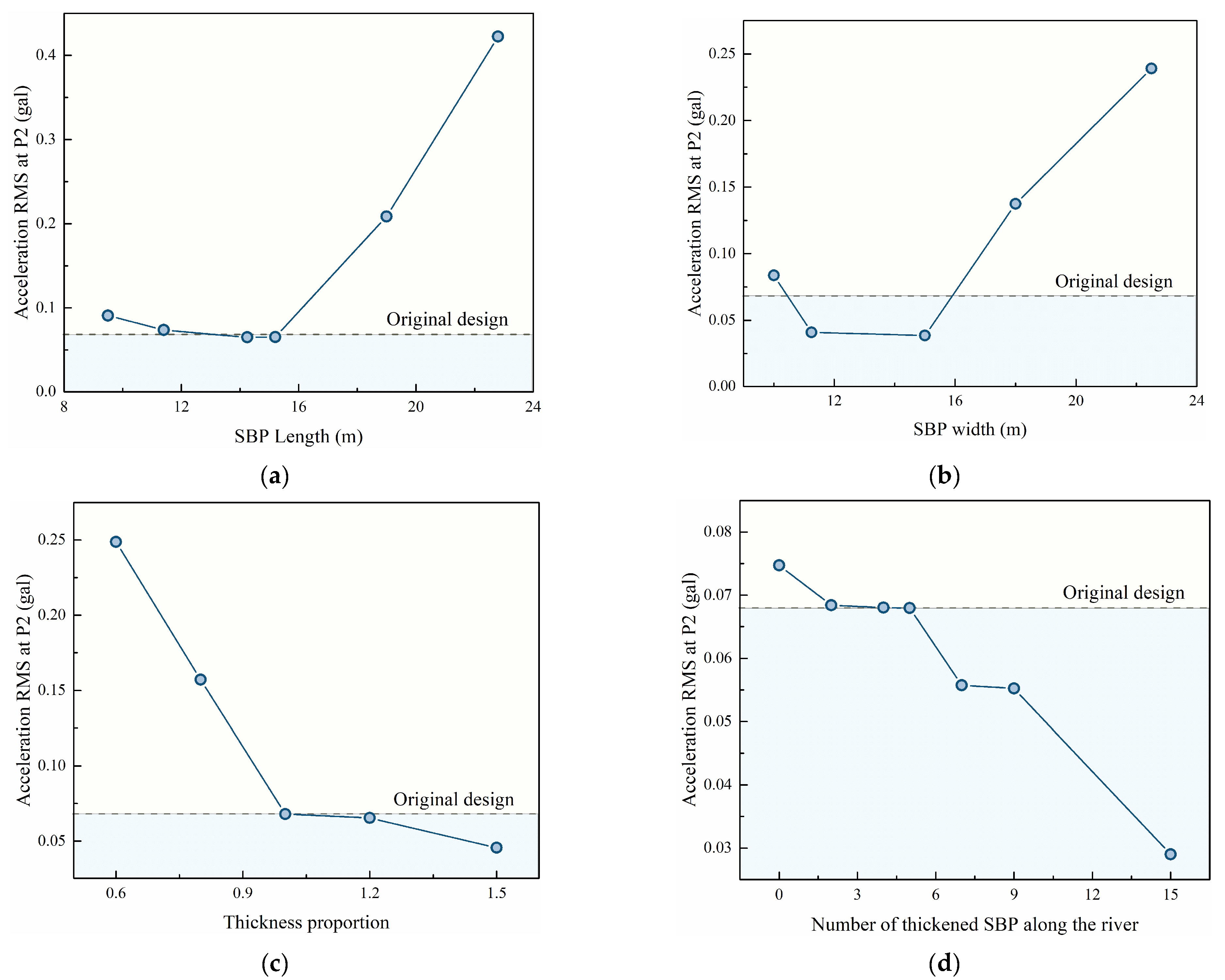
In order to investigate ground vibration reduction based on the SBP–foundation coupled system, sensitivity analyses of the physical dimensions of SBPs to ground vibration are conducted. It is found that there is an optimal length and width for the SBP that are beneficial to ground vibration reduction, because the natural frequency of SBP is relatively at a maximum when adopting the optimal length or width. The increase in SBP thickness can also reduce ground vibration, but only a substantial increase in the number of thickened SBPs has a significant vibration reduction effect. Based on the above results, an optimized design for SBP is presented. The analysis result shows that the optimized design can effectively reduce the ground vibration component induced by SBP.
In conclusion, this study can provide useful references for the reduction in ground vibration induced by high dam flood discharge during the design phase of similar hydropower stations. Compared to existing studies, the ground vibration reduction approach proposed in this study has advantages in terms of effectiveness and practicability.

Author Contributions

Conceptualization, J.L.; methodology, Y.Z. and C.L.; writing—original draft preparation, Y.Z.; resources, Y.L. and Y.Y.; data curation, B.M. and F.L.; funding acquisition, J.L. All authors have read and agreed to the published version of the manuscript.

Funding

The authors greatly acknowledge the financial support of National Key R&D Program of China, grant number 2022YFB4200704; National Natural Science Foundation of China, grant number 51909185; and Key Research and Development Program of Yunnan Province, grant number 202203AA080009.

Data Availability Statement

Data is contained within the article.

Conflicts of Interest

Author Yutong Li was employed by the company Ertan Hydropower Plant, Yalong River Hydropower Development Company, Ltd. The remaining authors declare that the research was conducted in the absence of any commercial or financial relationships that could be construed as a potential conflict of interest.

References

  1. Darbre, G.; De Smet, C.; Kraemer, C. Natural frequencies measured from ambient vibration response of the arch dam of Mauvoisin. Earthq. Eng. Struct. Dyn. 2000, 29, 577–586. [Google Scholar] [CrossRef]
  2. Zhang, J.W.; Hou, G.; Wang, H.; Zhao, Y.; Huang, J.L. Operation feature extraction of flood discharge structure based on improved variational mode decomposition and variance dedication rate. J. Vib. Control 2019, 26, 229–240. [Google Scholar] [CrossRef]
  3. Li, H.K.; Liu, B.; Huang, W.; Liu, H.; Wang, G. Vibration load identification in the time-domain of high arch dam under discharge excitation based on hybrid LSQR algorithm. Mech. Syst. Sig. Process. 2022, 177, 109193. [Google Scholar] [CrossRef]
  4. Kotlyakov, A.V.; Shumakova, E.M.; Artem’Ev, S.A. Dynamics of the coastal zone of the Kuibyshev and Saratov reservoirs in the Tolyatti area and its correlation with the operation regime of the Zhigulevskaya HPP. Water Resour. 2007, 34, 657–662. [Google Scholar] [CrossRef]
  5. Shumakova, E.M.; Kotlyakov, A.V.; Shumakov, G.V. The effect of vibrations in the Zhigulevskii hydropower structure on soils in the nearby territories of Tolyatti City. Water Resour. 2010, 37, 306–310. [Google Scholar] [CrossRef]
  6. Lyatkher, V.M.; Komel’kov, L.V.; Mazhbits, G.L. Seismic effects caused by discharged water through the waterworks. Int. J. Altern. Energy Ecol. 2015, 165, 70–84. [Google Scholar] [CrossRef]
  7. Wang, X.; Hu, Y.A.; Luo, S.Z.; Zhang, L.C.; Wu, B. Prototype observation and influencing factors of environmental vibration induced by flood discharge. Water Sci. Eng. 2017, 10, 78–85. [Google Scholar] [CrossRef]
  8. Liang, C.; Zhang, J.L.; Lian, J.J.; Liu, F.; Li, X.Y. Probabilistic analysis for the response of nonlinear base isolation system under the ground excitation induced by high dam flood discharge. Earthq. Eng. Eng. Vib. 2017, 16, 841–857. [Google Scholar] [CrossRef]
  9. Lian, J.J.; Chen, L.; Liang, C.; Liu, F. Presentation and verification of an optimal operating scheme aiming at reducing the ground vibration induced by high dam flood discharge. Int. J. Environ. Res. Public Health 2020, 17, 377. [Google Scholar] [CrossRef]
  10. Zhang, C. Recent developments on seismic safety evaluation of concrete dams. Earthq. Eng. Resil. 2022, 1, 7–20. [Google Scholar] [CrossRef]
  11. Fernández-Ruiz, J.; Rodríguez, L.E.M.; Costa, P.A.; Martínez-Díaz, M. Benchmarking of two three-dimensional numerical models in time/space domain to predict railway-induced ground vibrations. Earthq. Eng. Eng. Vib. 2021, 20, 242–256. [Google Scholar] [CrossRef]
  12. Colaço, A.; Costa, P.A.; Ferreira, C.; Parente, C.; Fernandez-Ruiz, J. Prediction of ground-borne vibration induced by impact pile driving: Numerical approach and experimental validation. Earthq. Eng. Eng. Vib. 2023, 22, 921–935. [Google Scholar] [CrossRef]
  13. Zhang, Y.; Lian, J.J.; Liu, F.; Zhang, W.J.; Li, S.H. Influencing factors of the ground vibration induced by flood discharge of high dams based on model experiments. J. Vib. Shock 2016, 35, 30–47. (In Chinese) [Google Scholar]
  14. Zhang, L.C.; Fan, X.M.; Luo, S.Z.; Wang, Y.J. Prediction method of ground vibration induced by flood discharge and energy dissipation of high dams. Adv. Sci. Technol. Water Resour. 2018, 38, 66–69. (In Chinese) [Google Scholar]
  15. Yin, R.G.; Zhang, J.H.; Zhang, J.M. Vibration source and shock absorption scheme research of near-field vibration caused by flood discharge and energy dissipation of a stilling pool. In Proceedings of the Geo-Shanghai 2014, Shanghai, China, 26–28 May 2014. [Google Scholar]
  16. Lian, J.J.; Zhang, Y.; Liu, F.; Zhao, Q. Analysis of the ground vibration induced by high dam flood discharge using the cross wavelet transform method. J. Renew. Sustain. Energy 2015, 7, 043146. [Google Scholar] [CrossRef]
  17. Narayanan, R. Pressure fluctuations beneath submerged jump. J. Hydraul. Div. 1978, 104, 1331–1342. [Google Scholar] [CrossRef]
  18. Armenio, V.; Toscano, P.; Fiorotto, V. On the effects of a negative step in pressure fluctuations at the bottom of a hydraulic jump. J. Hydraul. Res. 2000, 38, 359–368. [Google Scholar] [CrossRef]
  19. Liu, P.Q.; Li, A.H. Fluctuating uplift acting on rock blocks at the bottom of river bed and estimation of the limiting scour depth. J. Hydraul. Res. 2007, 45, 478–485. [Google Scholar]
  20. Frýba, L. History of Winkler Foundation. Veh. Syst. Dyn. 1995, 24, 7–12. [Google Scholar] [CrossRef]
  21. Filonenko-Borodich, M.M. Some approximate theories of elastic foundation. Uchenyie Zap. Mosk. Gos. Univ. Mekhanika 1940, 46, 3–18. [Google Scholar]
  22. Pasternak, P.L. On a New Method of Analysis of an Elastic Foundation by Means of Two Foundation Constants; Gosudarstvennoe Izdatelstvo Literaturi po Stroitelstvu I Arkhitekture: Moskow, Russia, 1954; pp. 1–56. (In Russian) [Google Scholar]
  23. Hetényi, M. Beams on Elastic Foundations; The University of Michigan Press: Ann Arbor, MI, USA, 1946. [Google Scholar]
  24. Zhang, J.M.; Peng, Y.; Xu, W.L. Hydraulic prediction of near-field vibrations induced by releasing flood. J. Hydraul. Eng. 2017, 143, 05017002. [Google Scholar] [CrossRef]
  25. Peng, Y.; Zhang, J.M.; Xu, W.L.; Rubinato, M. Experimental optimization of gate-opening modes to minimize near-field vibrations in hydropower stations. Water 2018, 10, 1435. [Google Scholar] [CrossRef]
  26. Ministry of Water Resources of the People’s Republic of China. Specification for Normal Hydraulic Model Test (SL 155-2012); China Water & Power Press: Beijing, China, 2012.
  27. Xu, Z.G. Elasticity; Higher Education Press, Inc.: Beijing, China, 2016. (In Chinese) [Google Scholar]
  28. Cao, Z.Y.; Yang, S.T. The Theory of Thick Plate Dynamics and Its Applications; Science Press: Beijing, China, 1983. [Google Scholar]
  29. Wang, X.; Luo, S.Z.; Zhang, L.C.; Chen, C.; Li, Z.Y.; Wu, X.Y. Flow-induced Vibration of Stilling Basin in One of Giant Hydropower Stations. In Proceedings of the Earth and Space, St. Louis, MI, USA, 27–29 October 2014; pp. 563–570. [Google Scholar]
  30. Biot, M.A. Bending of an Infinite Beam on an Elastic Foundation. J. Appl. Mech. 1937, 4, A1–A7. [Google Scholar] [CrossRef]
  31. Dong, J.; Peng, L. Researches on two-parameter model and foundation beams. J. Wuhan Univ. Hydraul. Electr. Eng. 1991, 24, 427–438. (In Chinese) [Google Scholar]
  32. Lin, J.Y.; Lian, J.J. Calculation for the amplitudes of fluctuating pressures acting at a single point and on an area under the impact of binary jet. J. Hydraul. Eng. 1988, 12, 34–40. (In Chinese) [Google Scholar]
  33. Sheng, Y.; Huang, Y. A free rectangular plate on the two-parameter elastic foundation. Appl. Math. Mech. 1987, 8, 325–338. [Google Scholar] [CrossRef]
  34. Cheng, X.S. A free rectangular plate on elastic foundation. Appl. Math. Mech. 1992, 13, 977–982. [Google Scholar] [CrossRef]
  35. Qu, Q.Z.; Liang, X.F.; Dong, X.J. Problem of rectangular plates with four free edges on Winkler elastic foundations. Struct. Environ. Eng. 1998, 2, 31–37. (In Chinese) [Google Scholar]
  36. Bhat, R.B. Natural frequencies of rectangular plates using characteristic orthogonal polynomials in Rayleigh-Ritz method. J. Sound Vib. 1985, 102, 493–499. [Google Scholar] [CrossRef]
  37. Liu, P.Q.; Li, A.H. Model discussion of pressure fluctuations propagation within lining slab joints in stilling basins. J. Hydral. Eng. 2007, 133, 618–624. [Google Scholar] [CrossRef]
  38. Yao, Z. Research on the Flow-Induced Vibration Response Characteristics of Slabs in Plunge Pool of Jinping-I High Arch Dam; Tianjin University: Tianjin, China, 2013. (In Chinese) [Google Scholar]
  39. Zhao, C.B. Coupled method of finite and dynamic infinite elements for simulating wave propagation in elastic solids involving infinite domains. Sci. China Ser. E Technol. Sci. 2010, 53, 1678–1687. [Google Scholar]
  40. Ministry of Water Resources of the People’s Republic of China. Design Specification for Spillway (SL253-2018); China Water & Power Press: Beijing, China, 2018.
  41. Chopra, A.K. Dynamics of Structures: Theory and Applications to Earthquake Engineering; Prentice Hall: Bergen, NJ, USA, 2001. [Google Scholar]
Figure 1. Diagram for the hydraulic structure and vibration source of the XHS project.
Water 16 01559 g001
Figure 2. Physical model and measuring point arrangement for hydraulic model tests of XHS: (a) the physical model; (b) measuring point arrangement.
Water 16 01559 g002
Figure 3. Polynomial function images of the RMS of flow excitations under different discharge schemes: (a) discharge scheme (a); (b) discharge scheme (c).
Water 16 01559 g003
Figure 4. Dynamic theoretical model of the SBP–foundation coupled system: (a) Kirchhoff plate; (b) Pasternak foundation.
Water 16 01559 g004
Figure 5. Layout of SBPs in the right stilling basin.
Water 16 01559 g005
Figure 6. Dynamic responses of the SBP named P1: (a) displacement time history; (b) acceleration time history.
Water 16 01559 g006
Figure 7. Finite element model for the surrounding ground of XHS.
Water 16 01559 g007
Figure 8. Acceleration response of P2 under working condition I.
Water 16 01559 g008
Figure 9. Comparison between the results of numerical calculation and prototype measurements.
Water 16 01559 g009
Figure 10. Ground vibrations at P2 under different optimization types: (a) length changes; (b) width changes; (c) thickness changes of equal proportions; (d) changes in the number of thickened SBP.
Water 16 01559 g010
Figure 11. Correlation between the ground acceleration RMS and nature frequency of SBP.
Water 16 01559 g011
Figure 12. Effect of SBP optimized design on ground vibration reduction.
Water 16 01559 g012
Table 1. Typical discharge schemes for polynomial fitting.
Discharge SchemeUpstream
Water Level (m)
Downstream
Water Level (m)
Opening Ratios of OrificesDegree of Fitting (R2)
1#–6# Surface Orifices (m)1#–5# Middle Orifices (m)
(a)372.78275.85Fully openedClosed0.9661
(b)380277.15Fully openedClosed0.9786
(c)353271.81Closed2.50.8981
(d)353272.89ClosedFully opened0.9318
(e)370274.30ClosedFully opened0.9459
(f)380276.11Fully openedFully opened0.9120
Table 2. Parameter values in the theoretical model.
Parameters of SBPParameters of Foundation
ParameterNotationValueParameterNotationValue
Elasticity modulusE30 GPaCompression modulus E s 10 GPa
Poisson’s ratioμ0.167Poisson’s ratio μ s 0.3
Densityρ2450 kg/m3
Table 3. Material parameter values in the finite element model.
MaterialGeotechnical
Type
Density (kg/m3)Elastic Modulus (MPa)Poisson’s Ratio
Surface soil of the ancient watercourse areaGravel clay1670600.38
Interlayer soil of the
ancient watercourse area
Sand gravel2125900.39
Downstream bedrockSilty mudstone258011,3000.3
Upstream bedrockWeak-weathered medium-fine
sandstone
260038,0000.225
Table 4. Working conditions considered in the verification of the evaluation approach.
Working ConditionStilling Basin Put
into Operation
Discharge
Scheme
IRight(a)
II(c)
IIILeft(a)
IV(c)
Table 5. Design schemes and the corresponding results for the sensitivity analysis of SBP size to ground vibration.
Optimization TypeDesign SchemesSBP
Length
(m)
SBP
Width
(m)
Thickened SBPDownstream SBPAcceleration
RMS at P2
(gal)
Thickness
(m)
SBP Number
Along River
Thickness
(m)
SBP Number
Along River
Length change19.5UUUUU0.09083
211.4UUUUU0.07376
314.25UUUUU0.06503
415.2UUUUU0.06531
519UUUUU0.20859
622.8UUUUU0.42226
Width
change
7U10UUUU0.08364
8U11.25UUUU0.04092
9U15UUUU0.03856
10U18UUUU0.13738
11U22.5UUUU0.23907
Thickness change (of equal proportions)12UU6U3.6U0.24868
13UU8U4.8U0.15715
14UU10U6U0.06802
15UU12U7.2U0.06541
16UU15U9U0.04560
Thickness change (in the number of thickened SBPs)17UUU0U150.07473
18UUU2U130.06842
19UUU4U110.06802
20UUU5U100.06795
21UUU7U80.05573
22UUU9U60.05524
23UUU15U00.02899
Notes: The symbol U in Table 5 denotes that the corresponding parameter of SBP is unchanged; the bolded value denotes the optimal value for the corresponding optimization type.
Disclaimer/Publisher’s Note: The statements, opinions and data contained in all publications are solely those of the individual author(s) and contributor(s) and not of MDPI and/or the editor(s). MDPI and/or the editor(s) disclaim responsibility for any injury to people or property resulting from any ideas, methods, instructions or products referred to in the content.

