


The Stresses and Deformations in the Abfraction Lesions of the Lower Premolars Studied by the Finite Element Analyses: Case Report and Review of Literature
 , , and
Abstract
1. Introduction
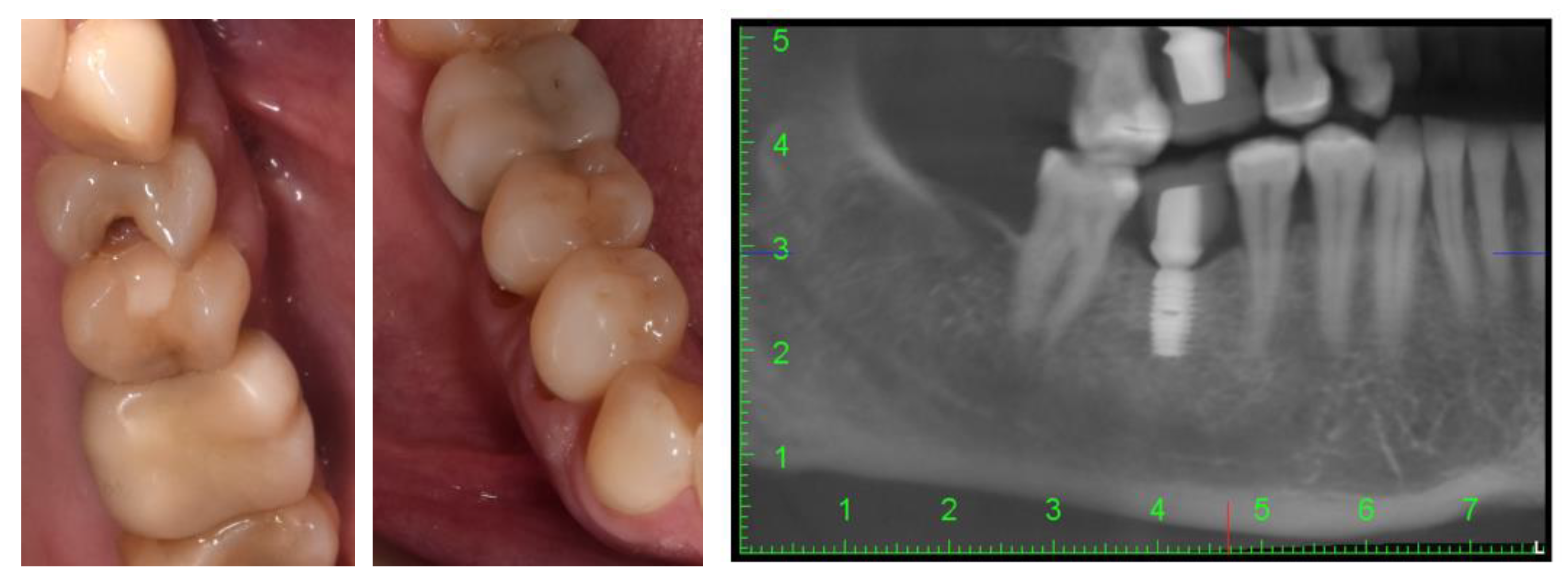
2. Case Description
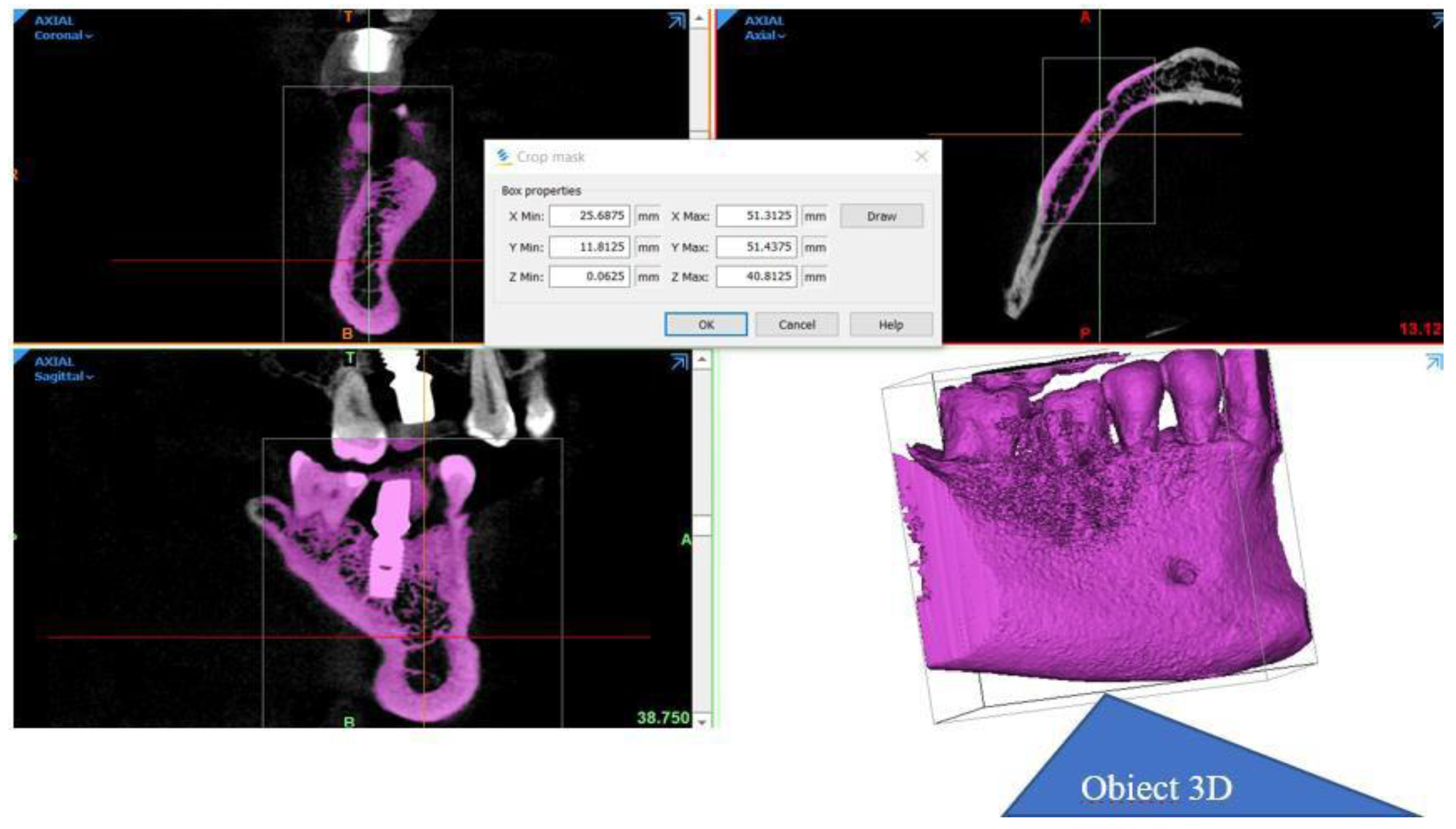
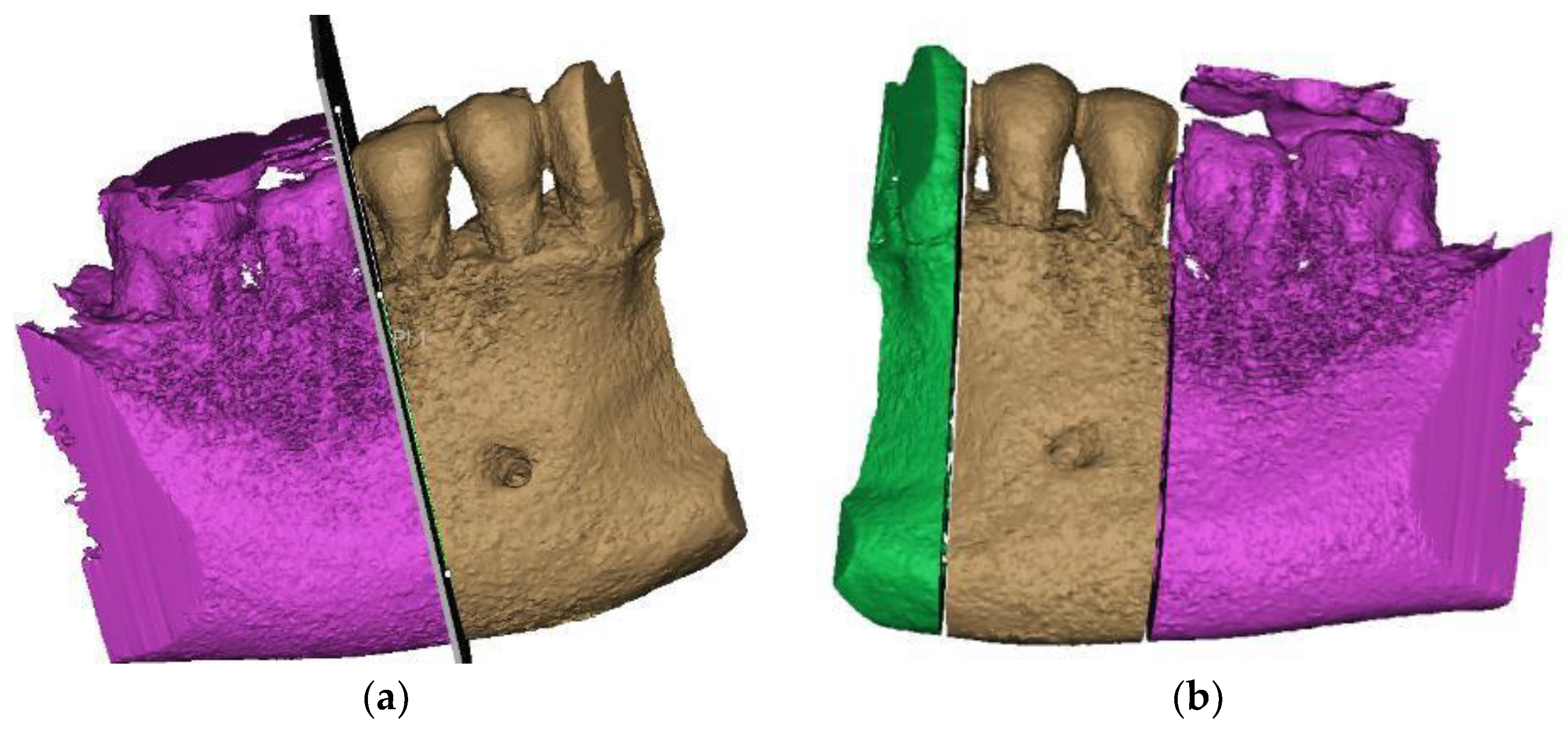
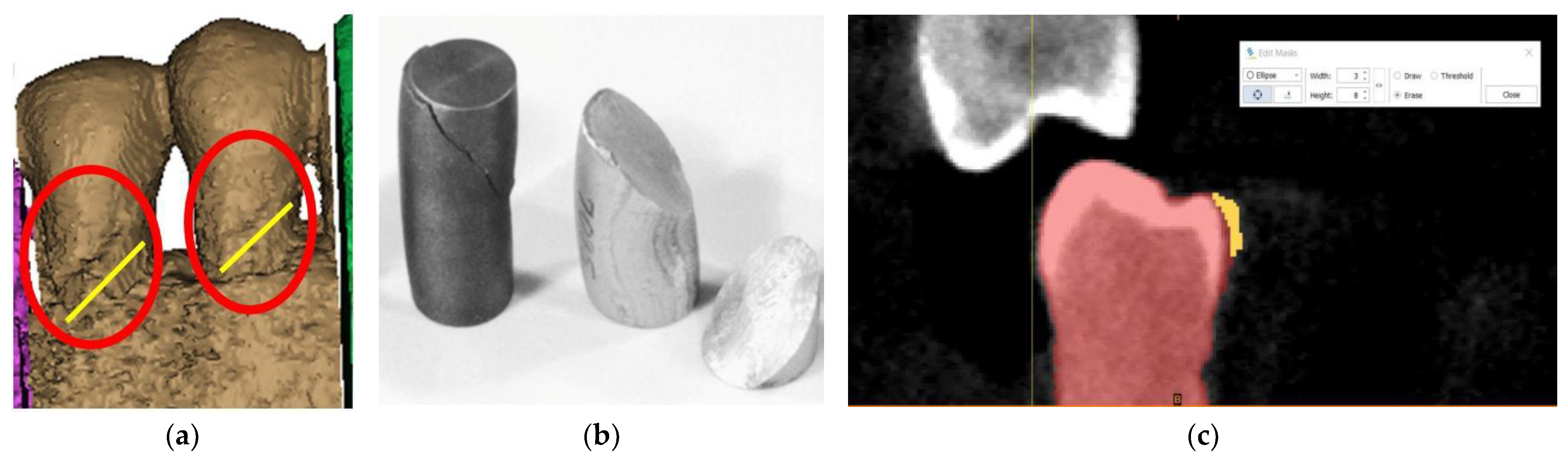
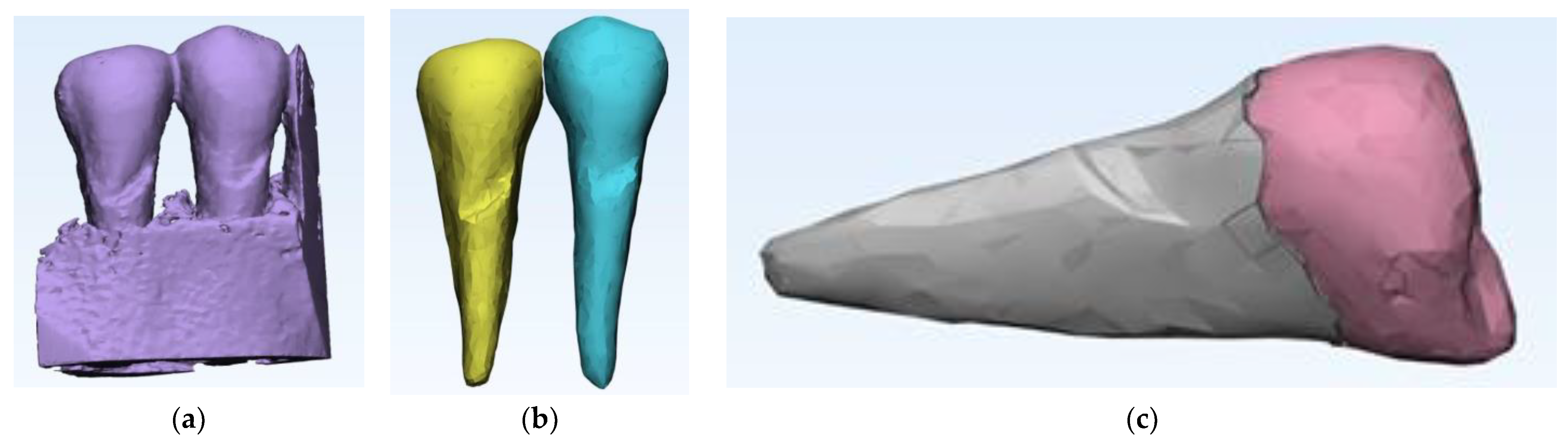
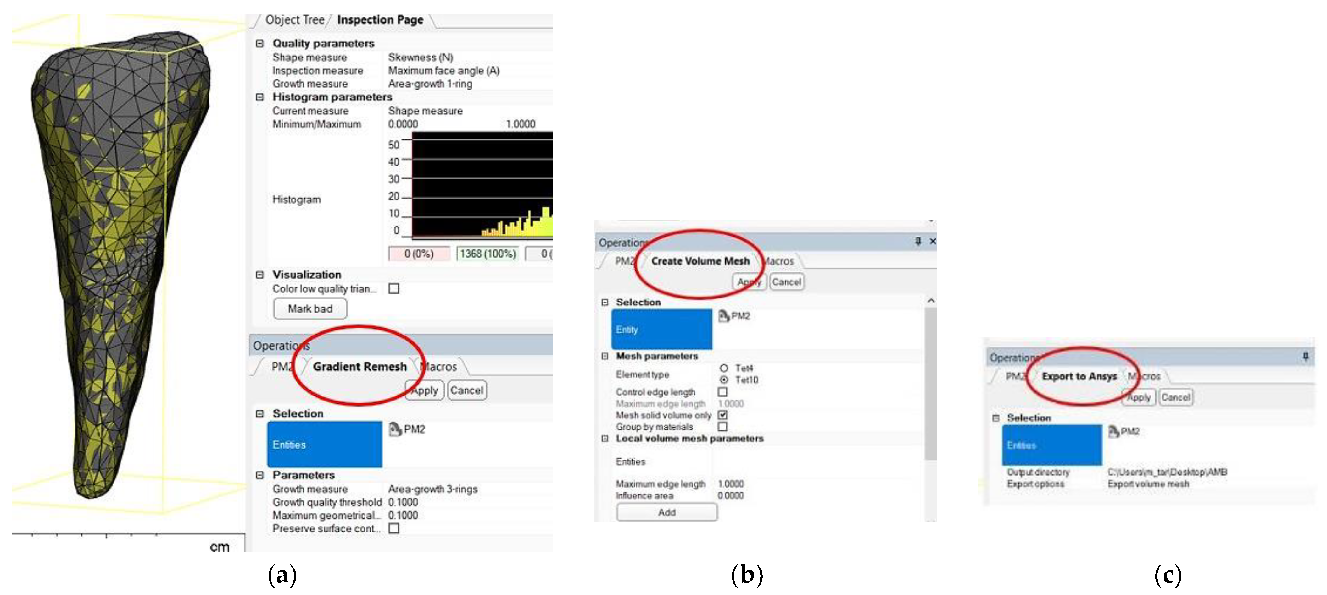
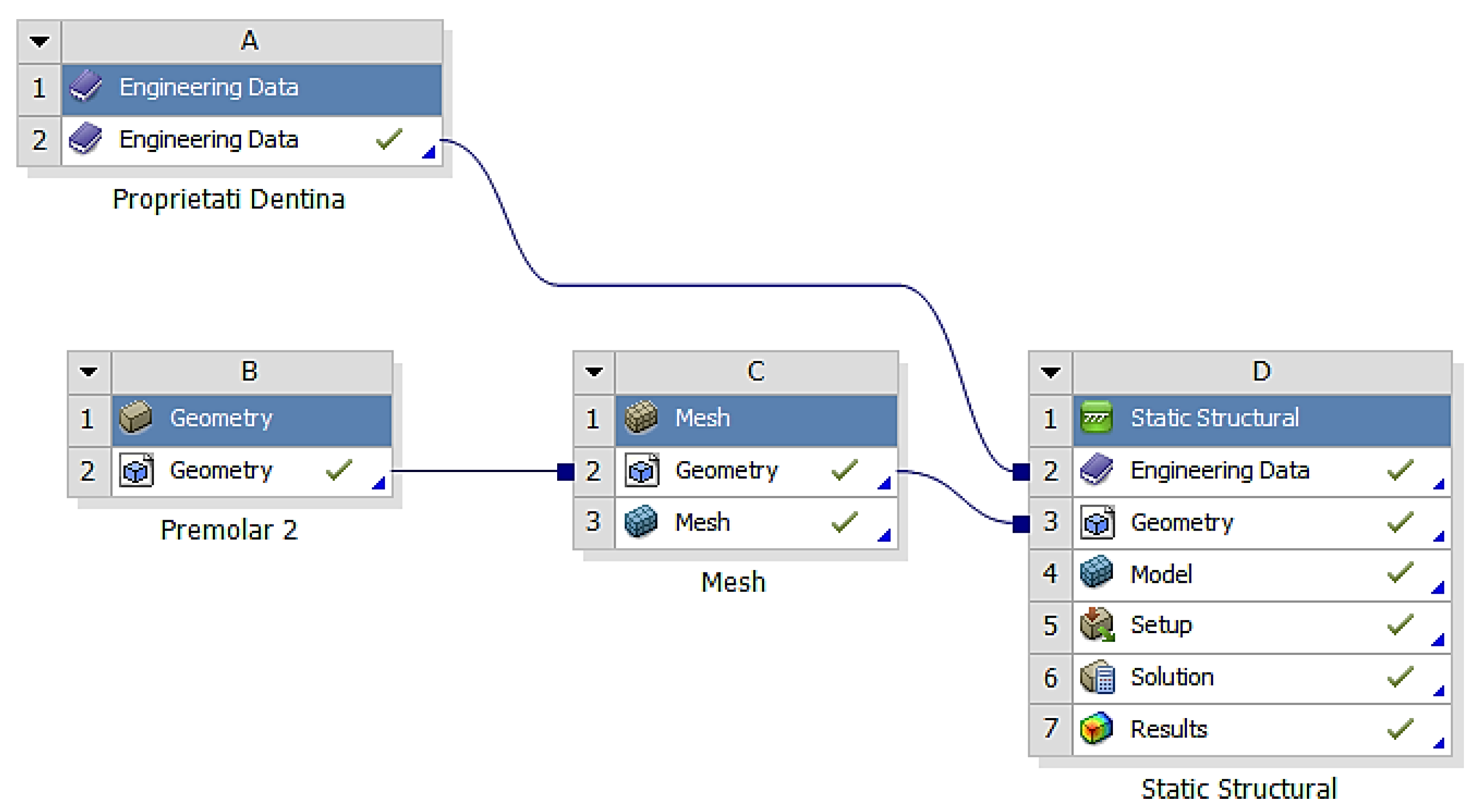
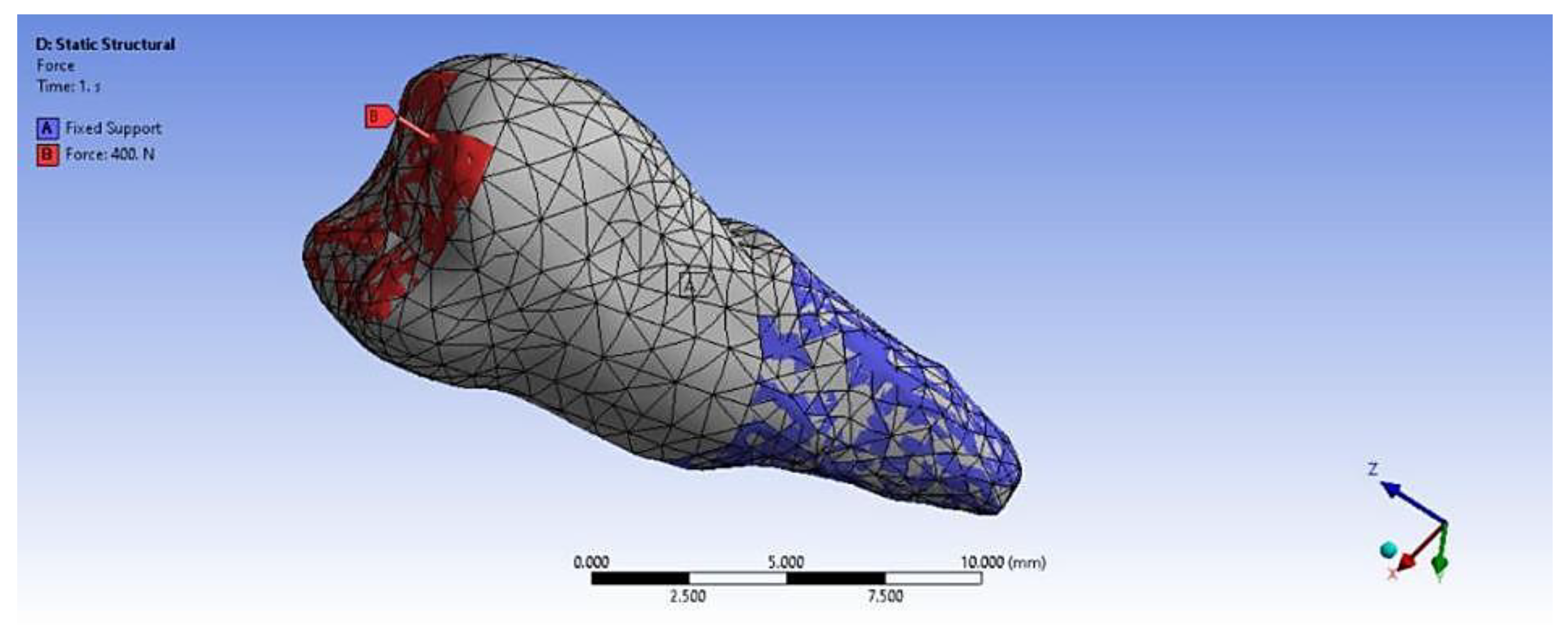
3. Finite Element Analysis (FEA) of Mandibular Right Premolars
4. Literature Review
5. Discussion
6. Conclusions
Author Contributions
Funding
Institutional Review Board Statement
Informed Consent Statement
Data Availability Statement
Conflicts of Interest
References
- Tsuchida, S.; Nakayama, T. Recent Clinical Treatment and Basic Research on the Alveolar Bone. Biomedicines 2023, 11, 843. [Google Scholar] [CrossRef] [PubMed]
- Foster, B.L.; Ao, M.; Salmon, C.R.; Chavez, M.B.; Kolli, T.N.; Tran, A.B.; Chu, E.Y.; Kantovitz, K.R.; Yadav, M.; Narisawa, S.; et al. Osteopontin regulates dentin and alveolar bone development and mineralization. Bone 2018, 107, 196–207. [Google Scholar] [CrossRef] [PubMed]
- Jiang, N.; Guo, W.; Chen, M.; Zheng, Y.; Zhou, J.; Kim, S.G.; Embree, M.C.; Songhee Song, K.; Marao, H.F.; Mao, J.J. Periodontal Ligament and Alveolar Bone in Health and Adaptation: Tooth Movement. Front. Oral Biol. 2016, 18, 1–8. [Google Scholar] [CrossRef] [PubMed]
- Bănuț Oneț, D.; Barbu Tudoran, L.; Delean, A.G.; Șurlin, P.; Ciurea, A.; Roman, A.; Bolboacă, S.D.; Gasparik, C.; Muntean, A.; Soancă, A. Adhesion of Flowable Resin Composites in Simulated Wedge-Shaped Cervical Lesions: An In Vitro Pilot Study. Appl. Sci. 2021, 11, 3173. [Google Scholar] [CrossRef]
- Zabolotna, I. Study of the morphological structure of enamel and correlation of its chemical composition with dentin in intact teeth and with a cervical pathology. J. Stomatol. 2021, 74, 9–15. [Google Scholar] [CrossRef]
- Goldberg, M. Non-carious cervical lesions (NCCL). J. Dent. Health Oral Disord. Ther. 2021, 12, 67–72. [Google Scholar] [CrossRef]
- Nascimento, M.M.; Dilbone, D.A.; Pereira, P.N.; Duarte, W.R.; Geraldeli, S.; Delgado, A.J. Abfraction lesions: Etiology, diagnosis, and treatment options. Clin. Cosmet. Investig. Dent. 2016, 3, 79–87. [Google Scholar] [CrossRef] [PubMed]
- Badavannavar, A.N.; Ajari, S.; Nayak, K.U.; Khijmatgar, S. Abfraction: Etiopathogenesis, clinical aspect, and diagnostic-treatment modalities: A review. Indian J. Dent. Res. 2020, 31, 305–311. [Google Scholar] [CrossRef] [PubMed]
- Konagala, R.K.; Mandava, J.; Anupreeta, A.; Mohan, R.B.; Murali, K.S.; Lakshman, V.U. AbfractionParadox—A Literature Review on Biomechanics, Diagnosis And Management. Int. J. Sci. Res. 2018, 7, 46–49. [Google Scholar]
- Rusu Olaru, A.; Popescu, M.R.; Dragomir, L.P.; Rauten, A.M. Clinical Study on Abfraction Lesions in Occlusal Dysfunction. Curr. Health Sci. J. 2019, 45, 390–397. [Google Scholar] [CrossRef]
- David, M.C.; Almeida, C.P.; Almeida, M.P.; Araújo, T.S.B.; Vanzella, A.C.B.; Filho, I.J.Z.; Bernardes, V.L. Prevalence of Non-Carious Cervical Lesions and Their Relation to Para-functional Habits: Original Study. Health Sci. J. 2018, 12, 557. [Google Scholar] [CrossRef]
- Zuza, A.; Racic, M.; Ivkovic, N.; Krunic, J.; Stojanovic, N.; Bozovic, D.; Bankovic-Lazarevic, D.; Vujaskovic, M. Prevalence of non-carious cervical lesions among the general population of the Republic of Srpska, Bosnia and Herzegovina. Int. Dent. J. 2019, 69, 281–288. [Google Scholar] [CrossRef] [PubMed]
- Peumans, M.; Politano, G.; Van Meerbeek, B. Treatment of noncarious cervical lesions: When, why, and how. Int. J. Esthet. Dent. 2020, 15, 16–42. [Google Scholar] [PubMed]
- Cruz, S.E.T.; Gadelha, V.R.; Gadelha, V.M. Non-carious cervical injuries: Etiological, clinical and therapeutic considerations. Rev. Cubana Estomatol. 2019, 56, 1–17. [Google Scholar]
- Plevris, V.; Tsiatas, G.C. Computational Structural Engineering: Past Achievements and Future Challenges. Front. Built Environ. 2018, 4, 21. [Google Scholar] [CrossRef]
- Liu, Y.; Wu, R.; Yang, A. Research on Medical Problems Based on Mathematical Models. Mathematics 2023, 11, 2842. [Google Scholar] [CrossRef]
- Agarwal, S.K.; Mittal, R.; Singhal, R.; Hasan, S.; Chaukiyal, K. Stress evaluation of maxillary central incisor restored with different post materials: A finite element analysis. J. Clin. Adv. Dent. 2020, 4, 22–27. [Google Scholar] [CrossRef]
- Liu, W.K.; Li, S.; Park, H.S. Eighty Years of the Finite Element Method: Birth, Evolution, and Future. Arch. Comput. Methods Eng. 2022, 29, 4431–4453. [Google Scholar] [CrossRef]
- Bandela, V.; Kanaparthi, S. Finite Element Analysis and Its Applications in Dentistry; IntechOpen: London, UK, 2021; Available online: https://www.intechopen.com/chapters/74006 (accessed on 6 October 2022). [CrossRef]
- Cipollina, A.; Ceddia, M.; Di Pietro, N.; Inchingolo, F.; Tumedei, M.; Romasco, T.; Piattelli, A.; Specchiulli, A.; Trentadue, B. Finite Element Analysis (FEA) of a Premaxillary Device: A New Type of Subperiosteal Implant to Treat Severe Atrophy of the Maxilla. Biomimetics 2023, 8, 336. [Google Scholar] [CrossRef]
- Lisiak-Myszke, M.; Marciniak, D.; Bieliński, M.; Sobczak, H.; Garbacewicz, Ł.; Drogoszewska, B. Application of Finite Element Analysis in Oral and Maxillofacial Surgery-A Literature Review. Materials 2020, 13, 3063. [Google Scholar] [CrossRef]
- Shruti, S.; Shrishail, K.V.; Priyanka, T. Applications of finite element analysis in dentistry: A review. J. Int. Oral Health 2021, 13, 415–422. [Google Scholar]
- Ornelas, D.A.T.; Vela, M.O.R.; García Palencia, P. Abfraction: Etiopathogenesis, clinical aspect, diagnosis and treatment, a review literature. Int. J. Appl. Dent. Sci. (IJADS) 2022, 8, 97–100. [Google Scholar] [CrossRef]
- Jakupovic, S.; Cerjakovic, E.; Topcic, A.; Ajanovic, M.; Konjhodzic-Prcic, A.; Vukovic, A. Analysis of the Abfraction Lesions Formation Mechanism by the Finite Element Method. Acta Inform. Medica 2014, 22, 241–245. [Google Scholar] [CrossRef]
- Soares, P.V.; Machado, A.C.; Zeola, L.F.; Souza, P.G.; Galvão, A.M.; Montes, T.C.; Pereira, A.G.; Reis, B.R.; Coleman, T.A.; Grippo, J.O. Loading and composite restoration assessment of various non-carious cervical lesions morphologies—3D finite element analysis. Aust. Dent. J. 2015, 60, 309–316. [Google Scholar] [CrossRef] [PubMed]
- Zeola, L.F.; Pereira, F.A.; Galvão, A.; Da, M.; Montes, T.C.; De Sousa, S.C.; Teixeira, D.N.R.; Reis, B.R.; Soares, P.V. Influence of noncarious cervical lesions depth, loading point application and restoration on stress distribution pattern in lower premolars: A 2D finite element analysis. Biosci. J. 2015, 31, 648–656. [Google Scholar] [CrossRef]
- Jakupović, S.; Anic, I.; Ajanovic, M.; Korac, S.; Konjhodzic, A.; Dzankovic, A.; Vuković, A. Biomechanics of cervical tooth region and noncarious cervical lesions of different morphology; three dimensional finite element analysis. Eur. J. Dent. 2016, 10, 413–418. [Google Scholar] [CrossRef]
- Zeola, L.F.; Pereira, F.A.; Machado, A.C.; Reis, B.R.; Kaidonis, J.; Xie, Z.; Townsend, G.C.; Ranjitkar, S.; Soares, P.V. Effects of non-carious cervical lesion size, occlusal loading and restoration on biomechanical behaviour of premolar teeth. Aust. Dent. J. 2016, 61, 408–417. [Google Scholar] [CrossRef] [PubMed]
- Costa, L.S.V.; Tribst, J.P.M.; Borges, A.L.S. Influence of the occlusal contacts in formation of Abfraction Lesions in the upper premolar. Braz. Dent. Sci. 2017, 20, 115–123. [Google Scholar] [CrossRef][Green Version]
- Machado, A.C.; Soares, C.J.; Reis, B.R.; Bicalho, A.A.; Raposo, L.; Soares, P.V. Stress-strain analysis of premolars with non-carious cervical lesions: Influence of restorative material, loading direction and mechanical fatigue. Oper. Dent. 2017, 42, 253–265. [Google Scholar] [CrossRef]
- Stănuşi, A.; Mercuţ, V.; Scrieciu, M.; Popescu, M.S.; Crăiţoiu Iacob, M.M.; Dăguci, L.; Castravete, S.; Vintilă, D.D.; Vătu, M. Effects of occlusal loads in the genesis of non-carious cervical lesions—A finite element study. Rom. J. Oral Rehabil. 2019, 11, 73–81. [Google Scholar]
- Vuković, A.; Jakupović, S.; Zukić, S.; Bajsman, A.; Gavranović Glamoč, A.; Šečić, S. Occlusal Stress Distribution on the Mandibular First Premolar—FEM Analysis. Acta Med. Acad. 2019, 48, 255–261. [Google Scholar] [CrossRef] [PubMed][Green Version]
- Stănuşi, A.; Mercuţ, V.; Scrieciu, M.; Popescu, S.M.; Iacov Crăiţoiu, M.M.; Dăguci, L.; Castravete, Ş.; Amărăscu, M.O. Analysis of stress generated in the enamel of an upper first premolar: A finite element study. Stoma Edu J. 2020, 7, 28–34. [Google Scholar] [CrossRef]
- Peres, T.S.; Teixeira, D.N.R.; Soares, P.V.; Zeola, L.F.; Machado, A.C. Influence of non-carious cervical lesions, bone attachment level, and occlusal load on the stress distribution pattern in maxillary premolars: Finite element analysis. Biosci. J. 2022, 38, e38072. [Google Scholar] [CrossRef]
- Shaik, I.; Dasari, B.; Shaik, A.; Doos, M.; Kolli, H.; Rana, D.; Tiwari, R.V.C. Functional Role of Inorganic Trace Elements on Enamel and Dentin Formation: A Review. J. Pharm. Bioallied Sci. 2021, 13 (Suppl. 2), S952–S956. [Google Scholar] [CrossRef] [PubMed]
- Lee, E.-S.; Wadhwa, P.; Kim, M.-K.; Bo Jiang, H.; Um, I.-W.; Kim, Y.-M. Organic Matrix of Enamel and Dentin and Developmental Defects. In Human Tooth and Developmental Dental Defects—Compositional and Genetic Implications; IntechOpen: London, UK, 2022; Available online: https://www.intechopen.com/chapters/77993 (accessed on 21 April 2023). [CrossRef]
- Roberts, W.E.; Mangum, J.E.; Schneider, P.M. Pathophysiology of Demineralization, Part I: Attrition, Erosion, Abfraction, and Noncarious Cervical Lesions. Curr. Osteoporos. Rep. 2022, 20, 90–105. [Google Scholar] [CrossRef]
- Stifler, C.A.; Jakes, J.E.; North, J.D.; Green, D.R.; Weaver, J.C.; Pupa, G. Crystal misorientation correlates with hardness in tooth enamels. Acta Biomater. 2021, 120, 124–134. [Google Scholar] [CrossRef]
- Koju, S.; Maharjan, N.; Yadav, D.K.; Bajracharya, D.; Baral, R.; Ojha, B. Morphological analysis of cementoenamel junction in permanent dentition based on gender and arches. J. Kantipur Dent. Coll. 2021, 2, 24–28. [Google Scholar]
- Nguyen, K.-C.T.; Yan, Y.; Kaipatur, N.R.; Major, P.W.; Lou, E.H.; Punithakumar, K.; Le, L.H. Computer-Assisted Detection of Cemento-Enamel Junction in Intraoral Ultrasonographs. Appl. Sci. 2021, 11, 5850. [Google Scholar] [CrossRef]
- Yap, R.C.; Alghanem, M.; Martin, N. A narrative review of cracks in teeth: Aetiology, microstructure and diagnostic challenges. J. Dent. 2023, 138, 104683. [Google Scholar] [CrossRef]
- Stănuși, A.; Ionescu, M.; Cerbulescu, C.; Popescu, S.M.; Osiac, E.; Mercuț, R.; Scrieciu, M.; Pascu, R.M.; Stănuși, A.Ş.; Mercuț, V. Modifications of the Dental Hard Tissues in the Cervical Area of Occlusally Overloaded Teeth Identified Using Optical Coherence Tomography. Medicina 2022, 58, 702. [Google Scholar] [CrossRef]
- Shen, L.; Barbosa de Sousa, F.; Tay, N.; Lang, T.S.; Kaixin, V.L.; Han, J.; Kilpatrick-Liverman, L.; Wang, W.; Lavender, S.; Pilch, S.; et al. Deformation behavior of normal human enamel: A study by nanoindentation. J. Mech. Behav. Biomed. Mater. 2020, 108, 103799. [Google Scholar] [CrossRef] [PubMed]
- Bhanderi, S. Facts about cracks in teeth. Prim. Dent. J. 2021, 10, 20–27. [Google Scholar] [CrossRef]
- Wan, B.; Shahmoradi, M.; Zhang, Z.; Shibata, Y.; Sarrafpour, B.; Swain, M.; Li, Q. Modelling of stress distribution and fracture in dental occlusal fissures. Sci. Rep. 2019, 9, 4682. [Google Scholar] [CrossRef] [PubMed]
- Morimoto, S.; Lia, W.K.C.; Gonçalves, F.; Nagase, D.Y.; Gimenez, T.; Raggio, D.P.; Özcan, M. Risk Factors Associated with Cusp Fractures in Posterior Permanent Teeth—A Cross-Sectional Study. Appl. Sci. 2021, 11, 9299. [Google Scholar] [CrossRef]
- Wilmers, J.; Bargmann, S. Nature’s design solutions in dental enamel: Uniting high strength and extreme damage resistance. Acta Biomater. 2020, 107, 1–24. [Google Scholar] [CrossRef] [PubMed]
- Goodacre, C.J.; Roberts, W.E.; Munoz, C.A. Noncarious cervical lesions: Morphology and progression, prevalence, etiology, pathophysiology, and clinical guidelines for restoration. J. Prosthodont. 2023, 32, e1–e18. [Google Scholar] [CrossRef] [PubMed]
- Tanaka, M.; Naito, T.; Yokota, M.; Kohno, M. Finite element analysis of the possible mechanism of cervical lesion formation by occlusal force. J. Oral Rehabil. 2003, 30, 60–67. [Google Scholar] [CrossRef] [PubMed]
- Maayan, E.; Ariel, P.; Waseem, H.; Andrey, G.; Daniel, R.; Rachel, S. Investigating the etiology of non-carious cervical lesions: Novel µCT analysis. J. Dent. 2023, 136, 104615. [Google Scholar] [CrossRef] [PubMed]
- Teixeira, D.N.R.; Zeola, L.F.; Machado, A.C.; Gomes, R.R.; Souza, P.G.; Mendes, D.C.; Soares, P.V. Relationship between noncarious cervical lesions, cervical dentin hypersensitivity, gingival recession, and associated risk factors: A cross-sectional study. J. Dent. 2018, 76, 93–97. [Google Scholar] [CrossRef]
- Lim, G.E.; Son, S.A.; Hur, B.; Park, J.K. Evaluation of the relationship between non-caries cervical lesions and the tooth and periodontal tissue: An ex-vivo study using micro-computed tomography. PLoS ONE 2020, 15, e0240979. [Google Scholar] [CrossRef]
- Donovan, T.E.; Marzola, R.; Murphy, K.R.; Cagna, D.R.; Eichmiller, F.; McKee, J.R.; Metz, J.E.; Albouy, J.P.; Troeltzsch, M. Annual Review of Selected Scientific Literature: Report of the Committee on Scientific Investigation of the American Academy of Resto-rative Dentistry. J. Prosthet. Dent. 2017, 118, 281–346. [Google Scholar] [CrossRef] [PubMed]
- Poiate, I.; Muramatsu, M.; Mori, M.; Campos, T.; Matsuda, K.; Lopez, M.; Poiate, E., Jr. Abfraction lesion in central incisor tooth: Displacement and stress evaluation by laser speckle and finite element analysis. Med. Res. Arch. 2023, 11, 1–20. [Google Scholar] [CrossRef]
- Yang, S.; Chung, H. Three-dimentional finite element analysis of a mandibular premolar with reduced periodontal support under a non-axial load. Oral Biol. Res. 2019, 43, 313–326. [Google Scholar] [CrossRef]
- Luchian, I.; Martu, M.A.; Tatarciuc, M.; Scutariu, M.M.; Ioanid, N.; Pasarin, L.; Kappenberg-Nitescu, D.C.; Sioustis, I.A.; Solomon, S.M. Using fem to assess the effect of orthodontic forces on affected periodontium. Appl. Sci. 2021, 11, 7183. [Google Scholar] [CrossRef]
- Alemayehu, D.B.; Jeng, Y.R. Three-Dimensional Finite Element Investigation into Effects of Implant Thread Design and Loading Rate on Stress Distribution in Dental Implants and Anisotropic Bone. Materials 2021, 14, 6974. [Google Scholar] [CrossRef] [PubMed]
- Germán-Sandoval, R.; Ortiz-Magdaleno, M.; Sánchez-Robles, P.; Zavala-Alonso, N.; Fernando Romo-Ramírez, G. Analysis of the Mechanical Behavior and Effect of Cyclic Fatigue on the Implant-Abutment Interface. Odovtos Int. J. Dent. Sci. 2021, 23, 104–114. [Google Scholar] [CrossRef]
- Nie, H.; Tang, Y.; Yang, Y.; Wu, W.; Zhou, W.; Liu, Z. Influence of a new abutment design concept on the biomechanics of peri-implant bone, implant components, and microgap formation: A finite element analysis. BMC Oral Health 2023, 23, 277. [Google Scholar] [CrossRef] [PubMed]
- Comaneanu, R.M.; Mihali, T.; Gioga, C.; Pangica, A.-M.; Perlea, P.; Coman, C.; Hancu, V.; Botoaca, O.; Voiculeanu, M.; Tarcolea, M. FEA on the biomechanical behavior of immediately loaded implants with different sizes. Rom. J. Stomatol. 2023, 69, 116–122. [Google Scholar] [CrossRef]
- Gönder, H.Y.; Mohammadi, R.; Harmankaya, A.; Yüksel, İ.B.; Fidancıoğlu, Y.D.; Karabekiroğlu, S. Teeth Restored with Bulk–Fill Composites and Conventional Resin Composites; Investigation of Stress Distribution and Fracture Lifespan on Enamel, Dentin, and Restorative Materials via Three-Dimensional Finite Element Analysis. Polymers 2023, 15, 1637. [Google Scholar] [CrossRef]
- Schmid, A.; Strasser, T.; Rosentritt, M. Finite Element Analysis of Occlusal Interferences in Dental Prosthetics Caused by Occlusal Adjustment. Int. J. Prosthodont. 2023, 36, 436–442. [Google Scholar] [CrossRef]
- Jakupović, S.; Šehić, A.; Julardžija, F.; Gavranović-Glamoč, A.; Sofić, A.; Bajsman, A.; Kazazić, L. The Influence of Different Occlusal Loading on Six Restorative Materials for Restoration of Abfraction Lesions—Finite Element Analysis. Eur. J. Dent. 2022, 16, 886–894. [Google Scholar] [CrossRef] [PubMed]
- Dam Van, V.; Trinh Hai, A.; Dung Dao, T.; Hai Trinh, D. Applications of Finite Element in Implant Dentistry and Oral Rehabilitation. Open Dent. J. 2021, 15, 392–397. [Google Scholar] [CrossRef]
- Reddy, M.S.; Sundram, R.; Eid Abdemagyd, H.A. Application of Finite Element Model in Implant Dentistry: A Systematic Review. J. Pharm. Bioallied Sci. 2019, 11 (Suppl. 2), S85–S91. [Google Scholar] [CrossRef] [PubMed]
- Rathod, D.K.; Chakravarthy, C.; Suryadevara, S.S.; Patil, R.S.; Wagdargi, S.S. Stress Distribution of the Zygomatic Implants in Post-mucormycosis Case: A Finite Element Analysis. J. Maxillofac. Oral Surg. 2023, 22, 695–701. [Google Scholar] [CrossRef] [PubMed]
- Lee, C.-H.; Mukundan, A.; Chang, S.-C.; Wang, Y.-L.; Lu, S.-H.; Huang, Y.-C.; Wang, H.-C. Comparative Analysis of Stress and Deformation between One-Fenced and Three-Fenced Dental Implants Using Finite Element Analysis. J. Clin. Med. 2021, 10, 3986. [Google Scholar] [CrossRef] [PubMed]
- Zupancic Cepic, L.; Frank, M.; Reisinger, A.; Pahr, D.; Zechner, W.; Schedle, A. Biomechanical finite element analysis of short-implant-supported, 3-unit, fixed CAD/CAM prostheses in the posterior mandible. Int. J. Implant Dent. 2022, 8, 8. [Google Scholar] [CrossRef] [PubMed]
- Ma, D.; Qian, J. Three-dimensional finite element stress analysis of surface-mounted inlays in repairing pulp-penetrating non-carious cervical lesion of maxillary first premolar. Hua Xi Kou Qiang Yi Xue Za Zhi 2023, 41, 541–553, (In English and Chinese). [Google Scholar] [CrossRef] [PubMed]
- Kamenskikh, A.A.; Sakhabutdinova, L.; Astashina, N.; Petrachev, A.; Nosov, Y. Numerical Modeling of a New Type of Prosthetic Restoration for Non-Carious Cervical Lesions. Materials 2022, 15, 5102. [Google Scholar] [CrossRef] [PubMed]
- Sender, R.S.; Strait, D.S. The biomechanics of tooth strength: Testing the utility of simple models for predicting fracture in geometrically complex teeth. J. R. Soc. Inteface 2023, 20, 20230195. [Google Scholar] [CrossRef]
- Pala, E.; Ozdemir, I.; Grund, T.; Lampke, T. The Influence of Design on Stress Concentration Reduction in Dental Implant Systems Using the Finite Element Method. Crystals 2024, 14, 20. [Google Scholar] [CrossRef]


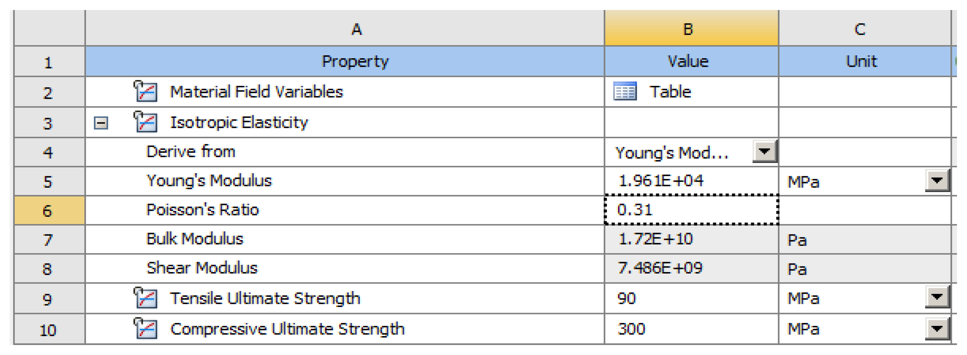
| Elastic Properties of Cement | Elastic Properties of Enamel | |
|---|---|---|
| Young’s modulus, MPa | 18,600 | 84,000 |
| Poisson’s ratio | 0.31 | 0.3 |
| Global Modulus, MPa | 16.316 | 70.000 |
| Transverse Modulus, MPa | 7099.2 | 32.308 |
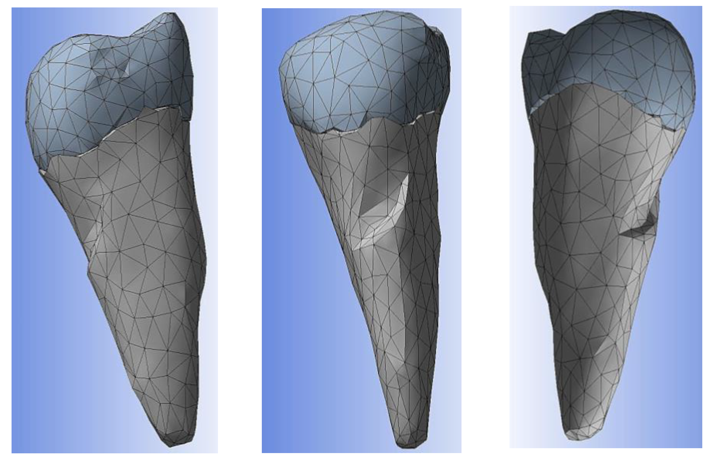
| Material | Condition | Statistics | |
|---|---|---|---|
| Nodes | Elements | ||
| Cement | Built mesh | 2685 | 1402 |
| Enamel | 2578 | 1316 | |
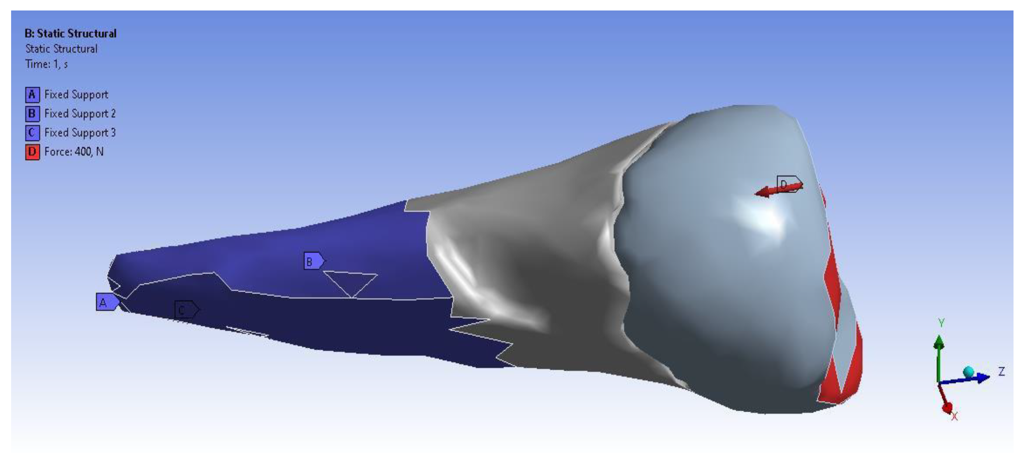
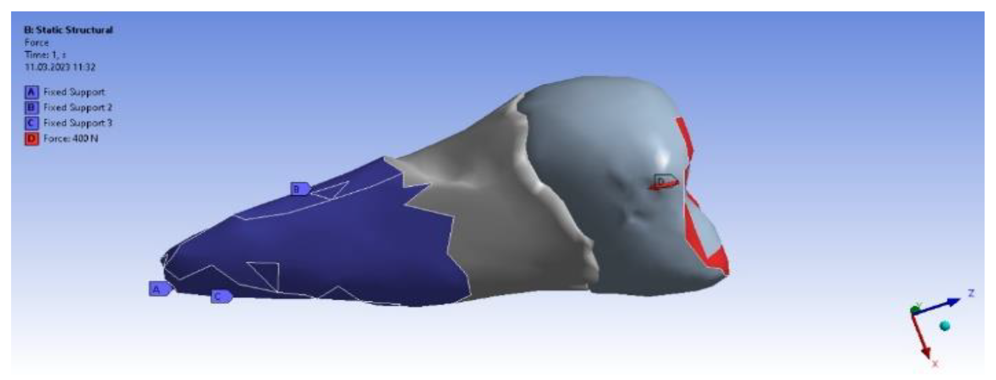
| Experimental Load Applied Perpendicularly | Experimental Load Applied Inclined at 45° | ||
|---|---|---|---|
| Type | Load | Type | Load |
| X component | −78 N (slope) | X component | −55 N (slope) |
| Y component | −78 N (slope) | Y component | −253 N (slope) |
| Z component | −385 N (slope) | Z component | −305 N (slope) |
| Resultant | 400 N | Resultant | 400 N |
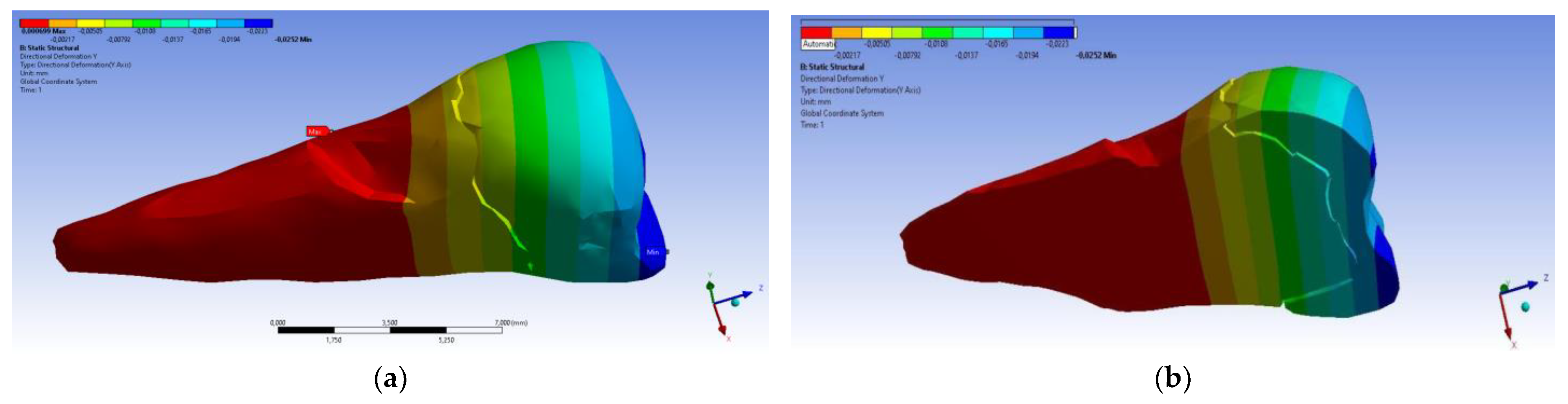
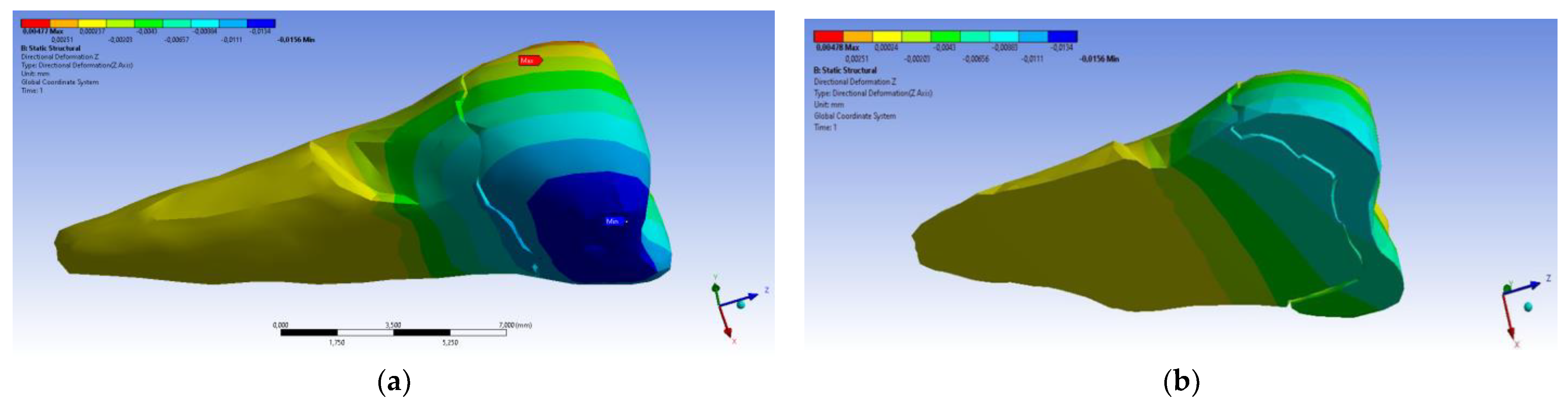
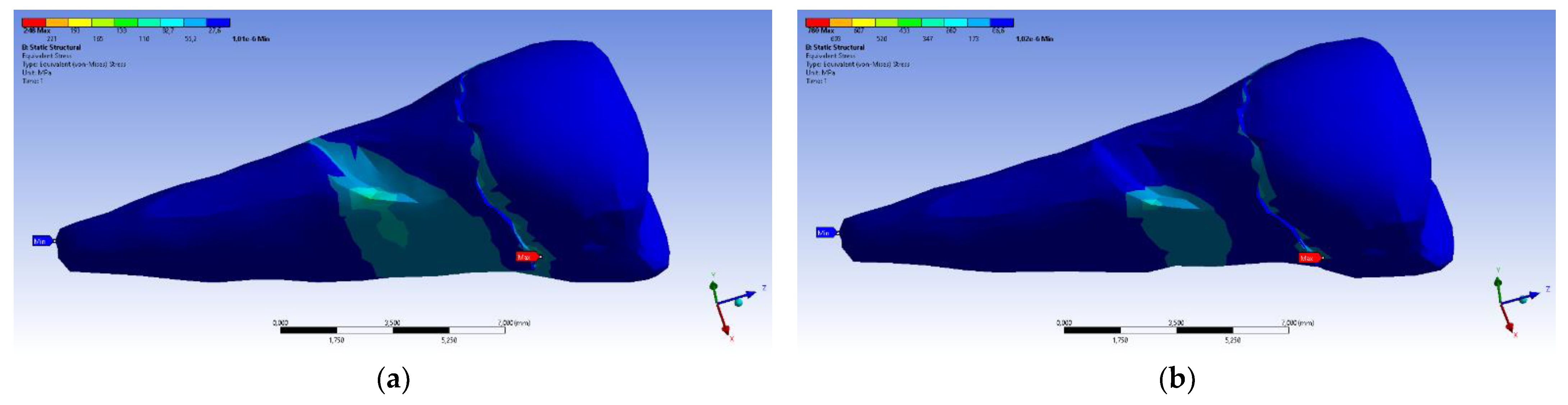
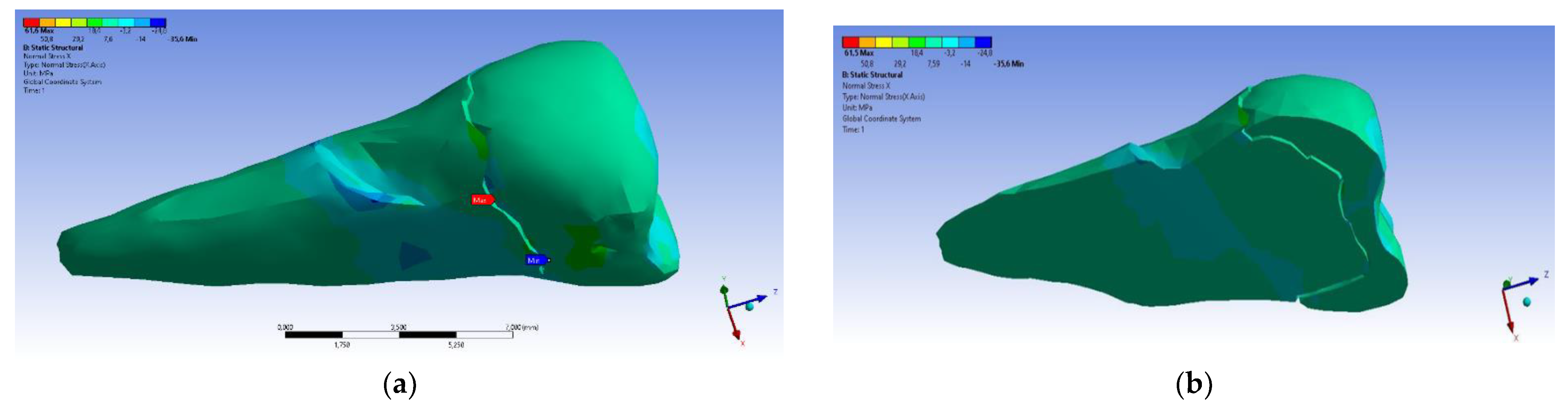
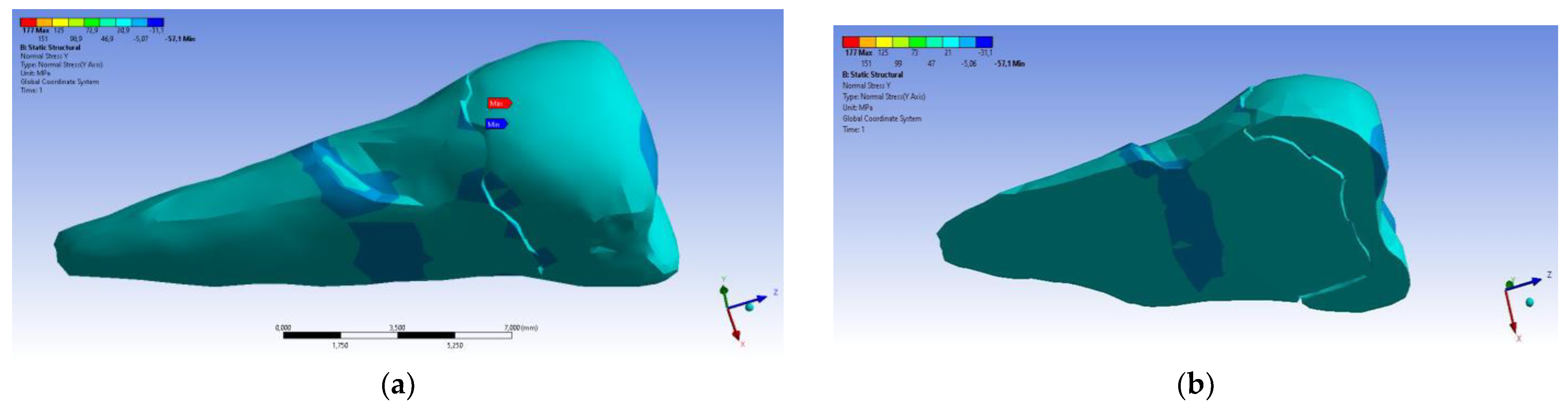
| Total Deformation | Deformation in X Direction | Deformation in Y Direction | Deformation in Z Direction | Equivalent Stress | Normal Stress X | Normal Stress Y | Normal Stress Z | Maximum Main Stress | Minimum Main Stress | Tangential Stress XY | Tangential Stress YZ | Tangential Stress XZ | |
|---|---|---|---|---|---|---|---|---|---|---|---|---|---|
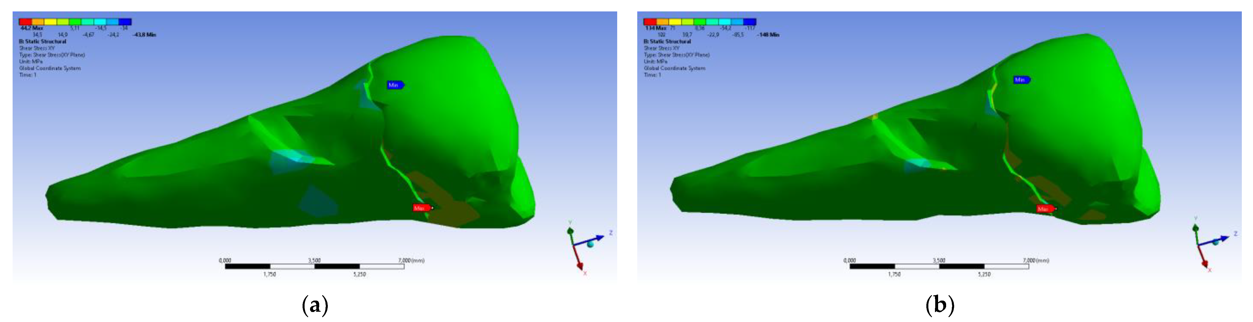
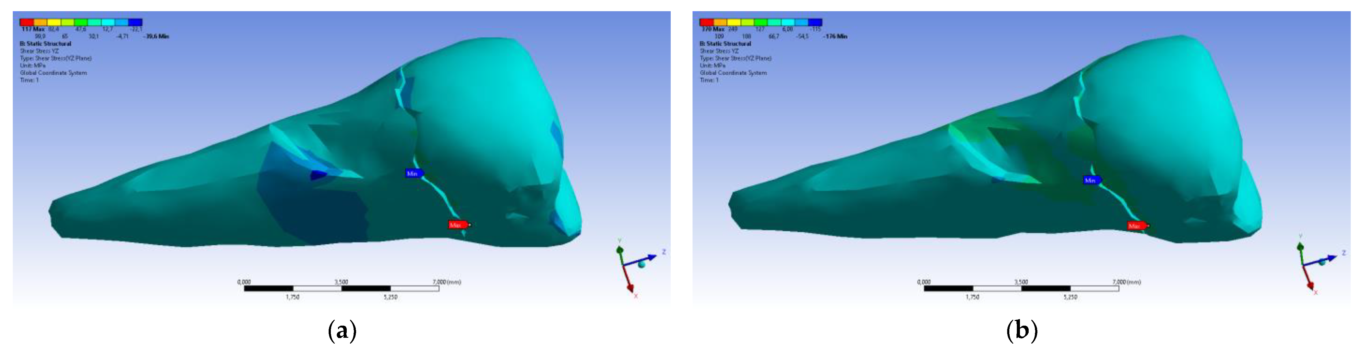
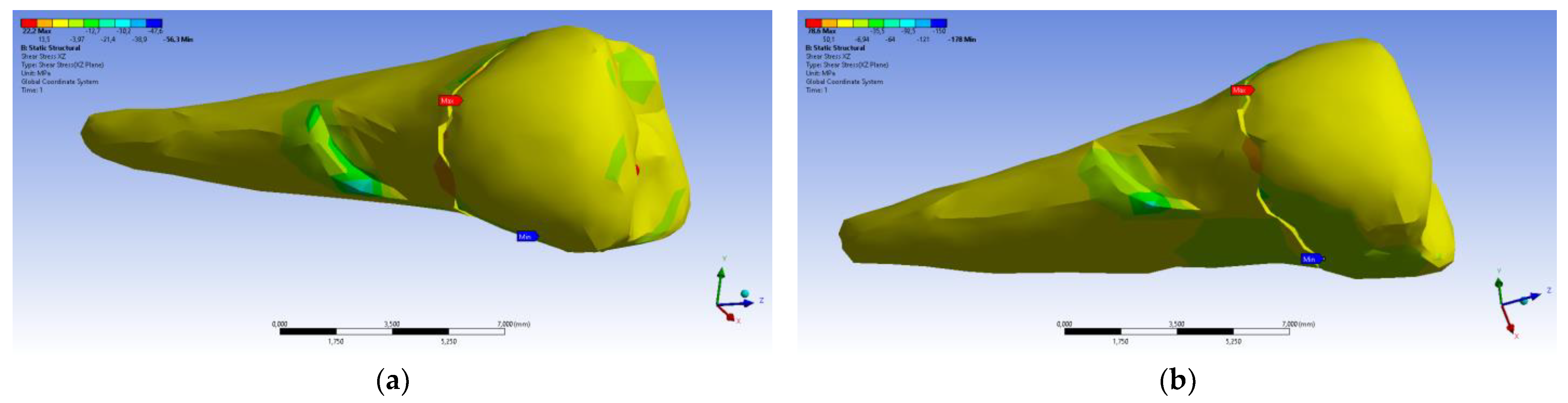
| Minimum | 0 mm | −4.24 × 10⁻³ mm | −2.52 × 10⁻² mm | −1.56 × 10⁻² mm | 1.01 × 10⁻⁶ MPa | −35.6 MPa | −57.1 MPa | −104 MPa | −15.2 MPa | −152 MPa | −43.7 MPa | −39.6 MPa | −56.3 MPa |
| Maximum | 2.77 × 10⁻² mm | 3.57 × 10⁻³ mm | 6.98 × 10⁻⁴ mm | 4.78 × 10⁻³ mm | 248 MPa | 61.5 MPa | 177 MPa | 72.2 MPa | 195 MPa | 21.4 MPa | 44.2 MPa | 117 MPa | 22.2 MPa |
| Minim. in | Cementum | Cementum | Enamel | Enamel | Cementum | Cementum | Enamel | Enamel | Enamel | Cementum | Enamel | Enamel | Cementum |
| Maxim. in | Enamel | Enamel | Cementum | Enamel | Cementum | Enamel | Enamel | Enamel | Enamel | Enamel | Cementum | Cementum | Cementum |
| Maximum Tangential Stress | Main Elastic Relative Deformation | Main Maximum Elastic Relative Deformation | Main Minimum Elastic Relative Deformation | Maximum Tangential Elastic Relative Deformation | Relative elastic Normal X Deformation | Relative Elastic Normal Y Deformation | Relative Elastic Normal Z Deformation | Relative Elastic Tangential XY Deformation | Relative Elastic Tangential YZ Deformation | Relative Elastic Tangential XZ Deformation | |||
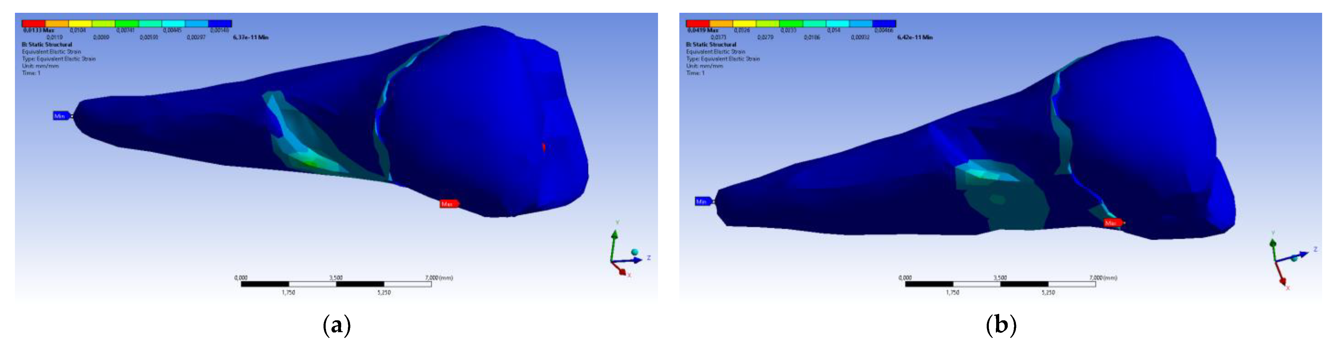
| Minimum | 5.4 × 10⁻⁷ MPa | 6.36 × 10⁻¹¹ mm/mm | −1.33 × 10⁻⁵ mm/mm | −1.05 × 10⁻² mm/mm | 7.6 × 10⁻¹¹ mm/mm | −2.26 × 10⁻³ mm/mm | −1.43 × 10⁻³ mm/mm | −3.45 × 10⁻³ mm/mm | −2.81 × 10⁻³ mm/mm | −4.09 × 10⁻³ mm/mm | −7.93 × 10⁻³ mm/mm | ||
| Maximum | 143 MPa | 1.33 × 10⁻² mm/mm | 9.66 × 10⁻³ mm/mm | 1.09 × 10⁻⁵ mm/mm | 2.01 × 10⁻² mm/mm | 1.37 × 10⁻³ mm/mm | 1.89 × 10⁻³ mm/mm | 3.14 × 10⁻³ mm/mm | 6.23 × 10⁻³ mm/mm | 1.65 × 10⁻² mm/mm | 3.13 × 10⁻³ mm/mm | ||
| Minim. in | Cementum | Cementum | Enamel | Cementum | Cementum | Cementum | Cementum | Cementum | Cementum | Cementum | Cementum | ||
| Maxim. in | Cementum | Cementum | Cementum | Cementum | Cementum | Cementum | Cementum | Enamel | Cementum | Cementum | Cementum |
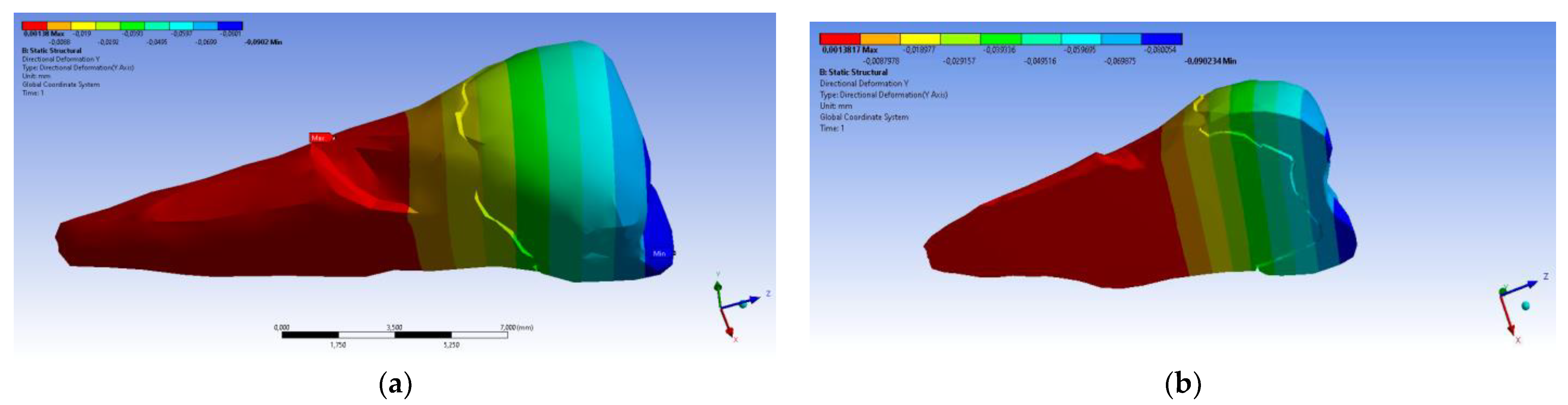
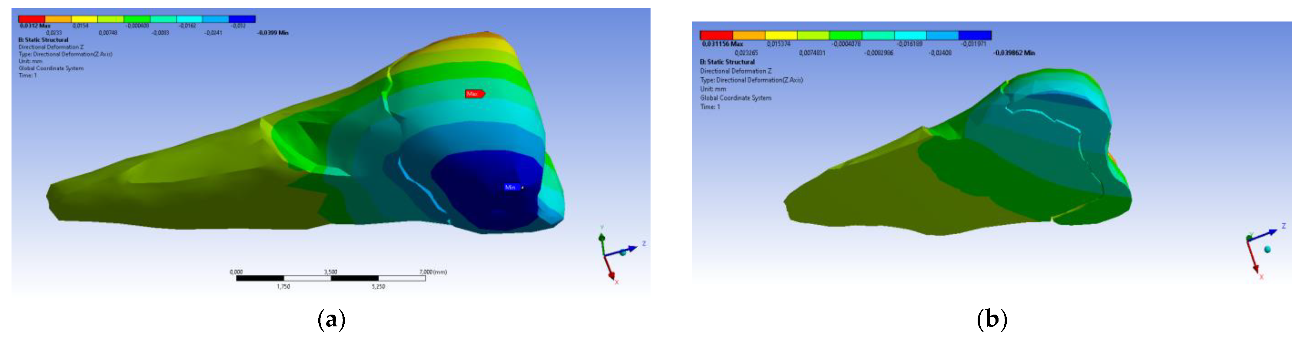
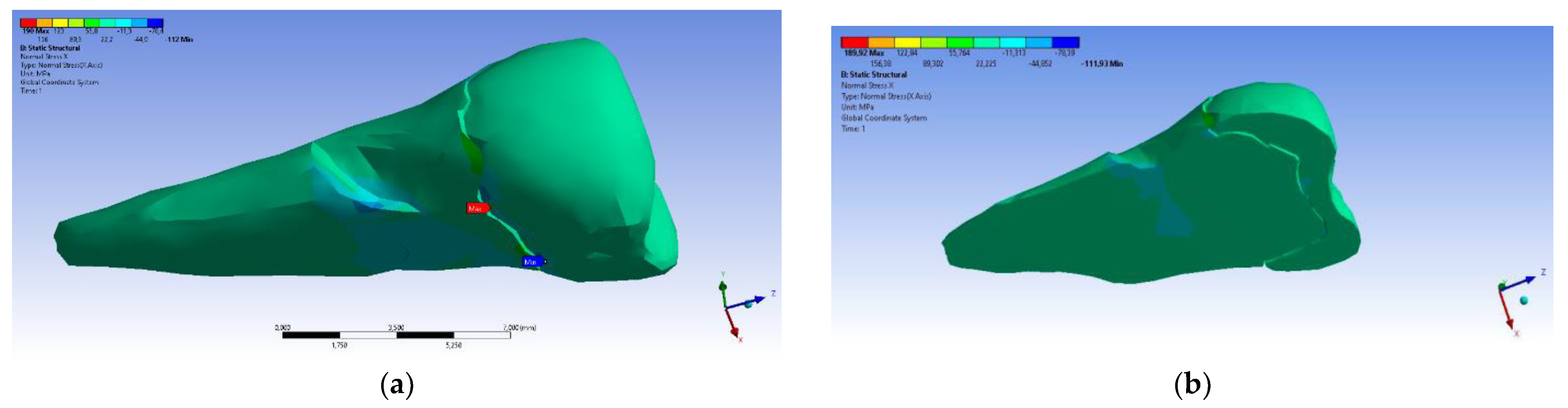
| Total Deformation | Deformation in X Direction | Deformation in Y Direction | Deformation in Z Direction | Equivalent Stress | Normal Stress X | Normal Stress Y | Normal Stress Z | Maximum Main Stress | Minimum Main Stress | Tangential Stress XY | Tangential Stress YZ | Tangential Stress XZ | |
|---|---|---|---|---|---|---|---|---|---|---|---|---|---|
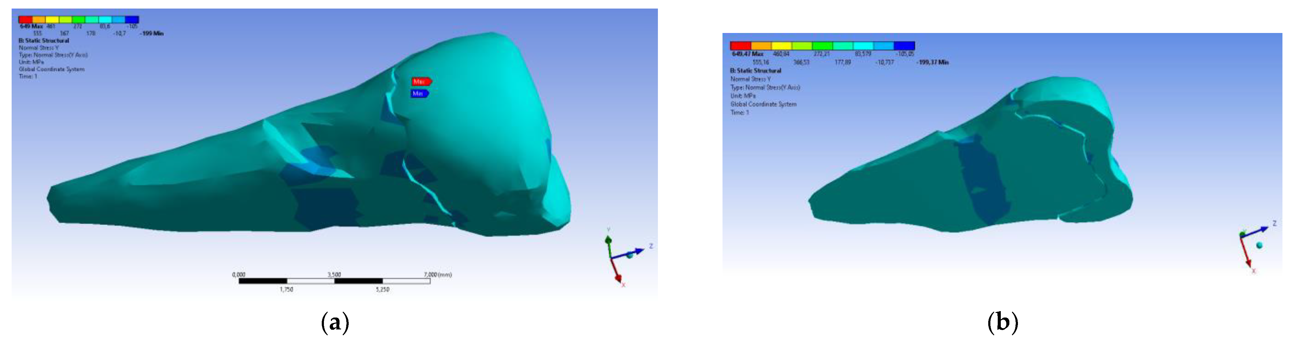
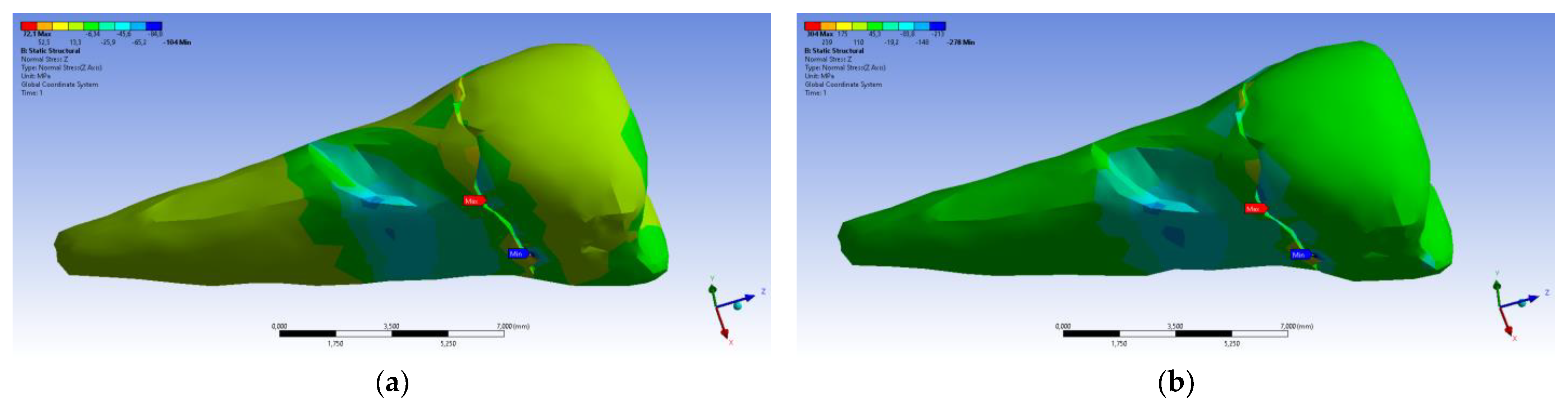
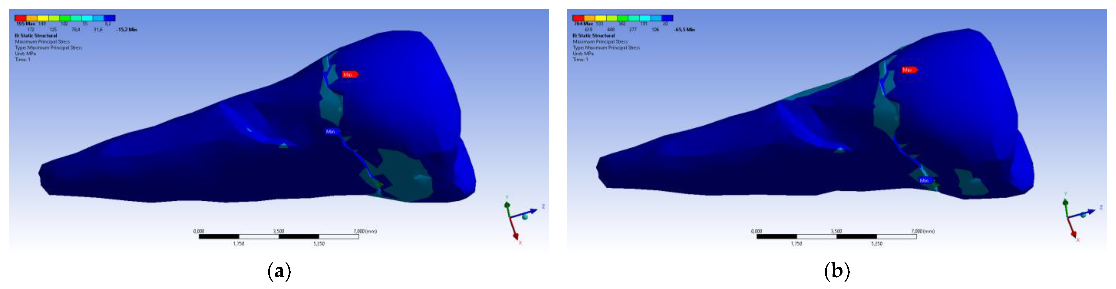
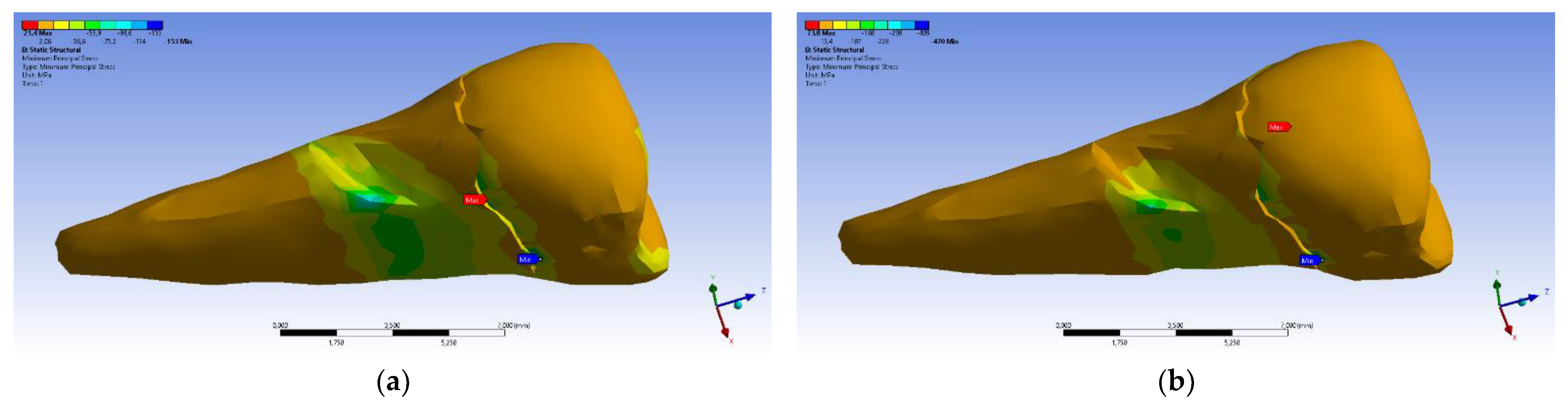
| Minimum | 0 mm | −6.1 × 10⁻³ mm | −9.02 × 10⁻² mm | −3.99 × 10⁻² mm | 1.02 × 10⁻⁶ MPa | −112 MPa | −199 MPa | −278 MPa | −65.5 MPa | −470 MPa | −148 MPa | −176 MPa | −178 MPa |
| Maximum | 9.28 × 10⁻² mm | 1.83 × 10⁻² mm | 1.38 × 10⁻³ mm | 3.12 × 10⁻² mm | 780 MPa | 61.5 MPa | 649 MPa | 304 MPa | 704 MPa | 73.8 MPa | 134 MPa | 370 MPa | 78.6 MPa |
| Minim. in | Cementum | Cementum | Enamel | Enamel | Cementum | Cementum | Enamel | Enamel | Enamel | Cementum | Enamel | Enamel | Cementum |
| Maxim. in | Enamel | Enamel | Cementum | Enamel | Cementum | Enamel | Enamel | Enamel | Enamel | Enamel | Cementum | Cementum | Cementum |
| Maximum Tangential Stress | Main Elastic Relative Deformation | Maximum Main Elastic Relative Deformation | Minimum Main Elastic Relative Deformation | Maximum Tangential Elastic Relative Deformation | Relative Elastic in Normal X Deformation | Relative Elastic in Normal Y Defomation | Relative Elastic in Normal Z Deformation | Relative Elastic Tangential XY Deformation | Relative Elastic Tangential YZ Deformation | Relative Elastic Tangential XZ Deformation | |||
| Minimum | 5.45 × 10⁻⁷ MPa | 6.42 × 10⁻¹¹ mm/mm | −1.31 × 10⁻⁵ mm/mm | −3.26 × 10⁻² mm/mm | 7.68 × 10⁻¹¹ mm/mm | −7.42 × 10⁻³ mm/mm | −5.42 × 10⁻³ mm/mm | −7.58 × 10⁻³ mm/mm | −6.29 × 10⁻³ mm/mm | −9.77 × 10⁻³ mm/mm | −2.51 × 10⁻² mm/mm | ||
| Maximum | 450 MPa | 4.19 × 10⁻² mm/mm | 3.08 × 10⁻² mm/mm | 7.02 × 10⁻⁵ mm/mm | 6.34 × 10⁻² mm/mm | 4.72 × 10⁻³ mm/mm | 6.75 × 10⁻³ mm/mm | 9.91 × 10⁻³ mm/mm | 1.88 × 10⁻² mm/mm | 5.21 × 10⁻² mm/mm | 1.11 × 10⁻² mm/mm | ||
| Minim. in | Cementum | Cementum | Enamel | Cementum | Cementum | Cementum | Cementum | Cementum | Cementum | Cementum | Cementum | ||
| Maxim. in | Cementum | Cementum | Cementum | Cementum | Cementum | Cementum | Cementum | Enamel | Cementum | Cementum | Cementum |
| Author, Reference No., Year | Title of Article | Aim of Study | Methodology/Data Analyzed with FEM | Values, Location of Load |
|---|---|---|---|---|
| Jakupović S. et al. 2014 [24] | Analysis of the abfraction lesions formation mechanism by the FEM | The authors evaluated stress in the lower premolar under static solicitations. | The intact tooth was scanned with a µCT 1076 SkyScan scanner (Kontich, Belgium). The images were reconstructed with the Nrecon (Skyscan) program into trans-axial sections. The additional reduction of input data was implemented, and the reconstruction of the 3D model was realized. Analyses of µCT section data were performed with the CTAn program (Skyscan), by using a 3D CAD tooth model (Matlab, Creo Parametric 1.0) with the Ansys Workbench 14.0 program. | 200 N Paraxial 40° |
| Soares P.V. et al. 2015 [25] | Loading and composite restoration assessment of different non-carious cervical lesions morphologies—3D FEA | The impacts of various occlusal loadings on premolars with NCCLs (unrestored or restored with composite resins) were studied with 3D FEA. | The intact tooth was set in a contact scanner (MDX-40, Roland Co., Osaka, Japan). The 3D models of FEA were manufactured by simulating an intact tooth model, models with NCCL morphologies, and restored models of all types of lesions. For creating the volume of external and internal shapes of hard and soft tissues of tooth, the STL files were exported to CAD (Computer Assisted Design; Rhino3D 4.0, Rhinoceros, USA) software. NCCL morphologies and their restorations were obtained through Boolean operations. The models were examined with the biomechanical analysis software ANSYS 12.0 (Ansys Workbench 12.0.1, PA, EUA), with STEP format software, for pre-processing, processing, and post-processing. After the conversion mesh test, the solid quadratic tetrahedral components with ten nodes were utilized. | 100 N Vertical Paraxial 45° buccal and palatal loading |
| Zeola I.F. et al. 2015 [26] | Influence of non-carious cervical lesions depth, loading point application and restora-tion on stress distribution pattern in lower pre-molars: A 2D FEA | The authors investigated the biomechanical behavior of lower premolars (the NCCL depth, load type, and restoration status) using FEA. | The intact extracted lower premolar scan images were studied with two-dimensional FEM. The scan data were exported to computer-aided design software (Autodesk Mechanical Desktop 6; Autodesk Inc., San Rafael, CA, USA) to generate the external contours of tooth structure and the polyether/polystyrene cylinder. The polyline module of CAD software was used for defining the tooth shapes, points, and line associations. The generated 2D FEA models were the healthy tooth, the three sizes of NCCL (small, medium, and deep), and the restored lesions. The obtained data were exported to CAE (computer-aided engineering) software (ANSYS 12.0, ANSYS Inc., Houston, TX, USA), using the *.IGES format. In the pre-processing phase, eight-noded isopara-metric plane elements were utilized (PLANE 183). The quantitative examination of strain (MPa) was determined at the enamel surface (on its upper wall), dentin (at the bottom wall), and dentin (on the lower wall) of the NCCLs. | 100 N Oblique loads on buccal cusp: on internal occlusal surface; on outer buccal cusp surface |
| Jakupović S. et al. 2016 [27] | Biomechanics of cervical tooth region and non-carious cervical lesions of different morphology three dimensional finite element analysis | The authors examined, through 3D FEA, the stress distribution and the biomechanical behavior of two types of occlusal charging of hard dental tissues of the lower first premolar with abfraction. | Three-dimensional models of the lower first premolar with wedge-shaped lesions and saucer-shaped lesions (U lesions) were realized. Microcomputed tomography (µCT) X-ray images were obtained. A scanner (type SkyScan 1076 Kontich, Belgium) was used. The images were rebuilt into transaxial sections by using Nrecon and CTAn program software (SkyScan). A total of 570 horizontal sections were selected for the making of the 3D models. MATLAB program packages (MathWorks, Inc., Natick, MA, USA) and Creo Parametric 1.0 CAD software were used for obtaining the volumetric 3D CAD tooth model of the lower first premolar with abfraction lesions. FEM analysis of strain under functional and nonfunctional occlusal charging was realized with CTAn program 1.10 and ANSYS Workbench version 14.0. | 200 N 40° |
| Zeola L.F. et al 2016 [28] | Effects of non-carious cervical lesion size, occlusal loading and restoration on biomechani-cal behaviour of premolar teeth | Investigation of the influence of NCCL dimensions, of restorations, and of occlusal loading direction on biomechanical behavior, as well as load tests and fracture toughness tests in the mandibular premolars, by FEA. | The intact extracted lower premolar scan images were studied with 2D FEM. The scan data were exported to computer-aided design software (Autodesk Mechanical Desktop 6; Autodesk Inc., San Rafael, CA, USA) to generate the external contours of tooth structure and the polyether/polystyrene cylinder. The polyline module of CAD software was used for defining the tooth shapes, points, and line associations. The generated 2D FEA models were the healthy tooth, the three sizes of NCCL (small, medium, and deep), and the restored lesions. The obtained data were exported to CAE (computer-aided engineering) software (ANSYS 12.0, ANSYS Inc., Houston, USA), using the *.IGES format. In the pre-processing phase PLANE 183 program was utilized. The quantitative examination of strain (MPa) was determined at the enamel surface (on its upper wall), dentine (at the bottom wall), and dentine of the NCCLs (on the lower wall). | 100 N Loads on outer and inner slopes of buccal cusp |
| Costa L.S.V. et al 2017 [29] | Influence of the occlusal contacts in formation of abfraction lesions in the upper premolar | The authors used FEA to observe the repartition of the stress over the upper premolar, applying centric contact, working contact, and balancing contact occlusal loading, to realize a biomechanical comparison of these contacts with increased potential to induce NCCLs. | In the 3D model, a first maxillary premolar was used, along with their specific oral tissues (enamel, dentin, a periodontal ligament), and the fixation cylinder. The file was acquired with CAD software in STL format (Rhinoceros 5.0 McNeel, North America, OH, USA). The anatomic contours were designed using the Biocad method. Analysis software ANSYS 15.0, ANSYS Inc., Houston, TX, USA, was used. The meshes were generated by applying the tetrahedral elements and the convergence test. The mechanical properties were taken from the specialty literature and then inserted into the software for the static structural analysis. Axial and paraxial loads (40°) were reproduced for central occlusion, laterality on the occlusal slope of the oral working cusp, and interference contact to balance movement on the occlusal slope of the facial cusp. The shapes of dental elements were examined through the colorimetric scale for the determination of qualitative similarity in the simulated occlusions. The stress distribution over the course of the loadings was displayed by colorimetric graphs. | Axial loads Paraxial 40° loads on oral and buccal cusp |
| Machado, A.C. et al. 2017 [30] | Stress-strain analysis of premolars with non-carious cervical lesions: influence of restorative material, loading direction and mechanical fatigue. | The purpose of the study was to evaluate the stress and strain dispersion in upper pre-molars affected by NCCLs in accordance with factors such as restorative technique, direction of occlusal loads, and mechanical fatigue. | A 3D finite element analysis linear elastic investigation was conducted using the anatomical shape of the hard periodontal tissues of the tooth (pulp, dentin, enamel, periodontal ligament, and cortical and medullar bones). The 14 models were generated by Rhinoceros 3D software (Rhinoceros, Miami, FL, USA) and simulated the sound tooth, unrestored buccal saucer-shaped NCCLs, and restored NCCLs with different types of dental materials (resin-modified glass ionomer, flowable composite resin, conventional nanofilled composite resin, lithium disilicate glass ceramic, and conventional nanofilled composite resin core associated with a 0.5-mm lithium disilicate glass ceramic laminate). With the processing analysis software (ANSYS 12.0, Ansys Workbench 12.0.1, Canonsburg, PA, USA) and the Standard for the Exchange of Product Data (STEP) format, the preprocessing, processing, and postprocessing analyses were performed. A strain gauge was connected to the buccal surface of the analyzed tooth for the registration of tooth strains before and after cyclic loading (200,000 cycles, 50 N). | 150 N Axial loads on both cusps Paraxial loads at a 45° angle on palatine cusp |
| Stănuşi, A. et al. 2019 [31] | Effects of occlusal loads in the genesis of non-carious cervical lesions—a finite element study | The size and repartition of stress in a maxillary first premolar of a 14-year-old patient suspected of having normal and heavy occlusal loads was studied. | A 3D model of the upper first premolar was realized through the CT images. Eight scenarios for the vertical loads and eight scenarios for the horizontal loads were used. To obtain the 3D model, the scanned images were converted by the MIMICS program and then processed in Abaqus/CAE so that they could be studied with FEA. The 3D virtual model contained the upper right first premolar tooth (enamel, dentine, and pulp) and their alveolar bone. The tooth was not presented rigidly in the bone, and between them existed the periodontal ligament with a 0.069 GPa elastic modulus. The FEA model presented tetrahedral elements (47,548 elements and 68,504 nodes). MIMICS Program and Abaqus/CAE were used. The 3D virtual model represented by the maxillary right first premolar and their alveoli were considered a parallelepiped. | 180 N and 532 N Horizontal loads Vertical loads |
| Vuković, A.A. et al. 2019 [32] | Occlusal Stress Distribution on the Mandibular First Premolar—FEM Analysis. | The purpose of this paper was to realize an FEM investigation of the dispensation of stress and of the deformation in a lower first premolar by applying two types of loads. | Microcomputed tomography (µCT) and a scanner (SkyScan 1076 Kontich, Belgium) were used on an intact premolar tooth under two types of loading. So a volumetric 3D CAD tooth model was obtained by the utilization of MATLAB (MathWorks, Inc., Natick, MA, USA) program packages and Creo Parametric 1.0 CAD software. On the tooth model, a wedge-shaped abfraction lesion was formed, and then the models were transferred to the FEA software ANSYS Workbench (14.0). A FE-mesh of models was implemented. The properties of the tooth tissues were utilized. The model was fixed to simulate the periodontal ligament movement under 300µm loads and the contact points with neighboring teeth. | 200 N Axial load Paraxial load |
| Stănuşi, A. et al. 2020 [33] | Analysis of stress generated in the enamel of an upper first premolar: a finite element study. | The aim of this article was to present the distribution and dimension of stress that appeared in the enamel of a maxillary first bicuspid tooth after exerting normal and excessive occlusal loadings. | A virtual model of the maxillary first premolar without any lesion was utilized to realize five models with distinct degrees of dental occlusal abrasion. The CT images of the maxillary premolar were transformed into 3D data by the MIMICS program (Materialise NV, Leuven, Belgium, 1992), and FEA was applied to study the resulting stresses. The scenarios obtained for occlusal loading of the 3D virtual model (14 in number) were investigated using the Abaqus/CAE program (ABAQUS Software, S.A.R.L., Versailles, France, 1994). The loads were exerted in the vertical and horizontal directions. The 3D models were tetrahedral elements with an average size of around 0.5 mm per surface. | 180 N and 532 N Horizontal load Vertical load |
| Peres, T.S. et al. 2022 [34] | Influence of non-carious cervical lesions, bone attachment level, and occlusal load on the stress distribution pattern in maxillary premolars: finite element analysis. | The purpose of the study was to analyze the stress distribution design by using 3D FEA in upper premolars with and without NCCL prior to and after rehabilitation with composite resin. The impact of different occlusal loads on various bone attachment levels and tooth structure was also evaluated. | Nine CAD models were obtained after the intact models, through Rhinoceros 3D software (Rhinoceros, Miami, FL, USA). The design of the cervical area varied (intact tooth, wedge-shaped NCCL, restored NCCL with composite resin, but also normal level of bone, or with vertical and horizontal bone loss). For each model, vertical, buccal, and palatal loads were simulated. The analysis software ANSYS 12.0 (Ansys Workbench 12.0.1, Canonsburg, PA, USA). The Standard for the Exchange of Product Data (STEP) format was used, with preprocessing, processing/data calculation, and post-processing/analysis of stress dispersation. Stress values were collected after processing the models (maximum principal stress and minimum principal stress). | 100 N Vertical load Buccal load Palatal load |
| No. | Author, Reference No., Year of Publishing | Main Results and Conclusions |
|---|---|---|
| 1 | Jakupović S. et al. [24] 2014 | The action of occlusal loads (especially paraxial one) induces considerable stress in the cervical sub-superficial stratum of enamel. The stress values of the cervical area due to the paraxial loads are about five times higher in comparison with the superficial enamel layer. |
| 2 | Soares P.V. et al. [25] 2015 | The morphology of NCCLs presented reduced consequences for the stress distribution design. The loading type and existence of composite resin restorations affected the biomechanical comportment of the maxillary premolars. |
| 3 | Zeola I.F. et al. [26] 2015 | The depth of NCCLs is related to the intensification of the magnitude and the expansion of strain concentration. The application of loads on the external slope of the buccal cusps in mandibular premolars created a higher possibility of fracture in comparison with the application on the internal slope. Resin composite restoration of lesions augments the structural integrity and the biomechanics of roundabout NCCLs close to the healthy teeth. |
| 4 | Jakupović S. et al. [27] 2016 | The exposure to occlusal loadings induces the progression of abfraction lesions. The type of action of these loadings impacts the stress intensity in the cervical area of teeth. The shape of abfraction lesions represents a major factor in the dispersal of internal stress. Underneath occlusal loads, V-shaped abfraction lesions presented notably higher stress accumulation in comparison with U-shaped abfraction lesions. |
| 5 | Zeola L.F. et al [28] 2016 | The exposure to occlusal loadings induces the progression of abfraction lesions. The type of action of these loadings determines the stress intensity in the cervical area of teeth. The eccentric occlusal loads induced excessive calculated stress values in all hard tissues of the tested tooth models. The shape of the abfraction lesions also impacts the partition of internal stress in the hard tissues of the tooth. |
| 6 | Costa L.S.V. et al [29] 2017 | For the quantitative comparison, the results appear in a table. The maximum values, which represent the concentrations of higher stress, are located in the enamel rather than the dentine. Eccentric contacts also present a higher possibility of progressing the abfraction lesions in the cervical area of the teeth and thus developing the size of tensile and shear stresses. |
| 7 | Machado, A.C. et al. [30] 2017 | The presence of NCCLs associated with paraxial loads determined a higher stress concentration in the cervical area of the tooth. The paraxial load represented the major factor that impacted the biomechanical behavior of teeth affected by NCCLs. The restored NCCLs with composite resin alone or with ceramic laminates appears to be the optimum manner of direct rehabilitation since their biomechanical behaviors were almost identical with those of the sound teeth. |
| 8 | Stănuşi, A. et al. [31] 2019 | The highest values of stress were situated in the oral cervical area, but may appear in other tooth regions too, where NCCLs are not commonly found. This fact implies that the genesis of cervical noncarious lesions is multifactorial. |
| 9 | Vuković, A.A. et al [32] 2019 | Under the action of occlusal paraxial loads, the strain values were greater and more notable in the cervical area. In an abfraction lesion, under a paraxial load, the measured stress values were extremely high. Exposure to the stress of V abfraction lesions will determine their deepening. The deformation of the tooth below the paraxial load was approximately 10 times greater than below the axial load. |
| 10 | Stănuşi, A. et al. [33] 2020 | Compressive stress predominated in the simulations of premolar models with horizontal occlusal abrasion. Both compressive and tensile stresses appeared in the simulations of the affected tooth models with oblique occlusal abrasions. The exceeding vertical and horizontal loads were prejudicial, regardless of their magnitude. |
| 11 | Peres, T.S. et al. [34] 2022 | The presence of NCCL intensified the tensile stress concentration in the cervical third of the buccal surface. The tensile stress concentrations were the same in healthy and restored models. The stress level at the periodontal bone level was not affected by the presence or absence of NCCL, but it was associated with the occlusal load. The existence of NCCL contributed to the apparition of an excessive stress concentration in the tooth model cervical area, particularly when the oblique occlusal loads acted. |
Disclaimer/Publisher’s Note: The statements, opinions and data contained in all publications are solely those of the individual author(s) and contributor(s) and not of MDPI and/or the editor(s). MDPI and/or the editor(s) disclaim responsibility for any injury to people or property resulting from any ideas, methods, instructions or products referred to in the content. |
© 2024 by the authors. Licensee MDPI, Basel, Switzerland. This article is an open access article distributed under the terms and conditions of the Creative Commons Attribution (CC BY) license (https://creativecommons.org/licenses/by/4.0/).
Share and Cite
Costăchel, B.C.; Bechir, A.; Târcolea, M.; Mihai, L.L.; Burcea, A.; Bechir, E.S. The Stresses and Deformations in the Abfraction Lesions of the Lower Premolars Studied by the Finite Element Analyses: Case Report and Review of Literature. Diagnostics 2024, 14, 788. https://doi.org/10.3390/diagnostics14080788
Costăchel BC, Bechir A, Târcolea M, Mihai LL, Burcea A, Bechir ES. The Stresses and Deformations in the Abfraction Lesions of the Lower Premolars Studied by the Finite Element Analyses: Case Report and Review of Literature. Diagnostics. 2024; 14(8):788. https://doi.org/10.3390/diagnostics14080788
Chicago/Turabian StyleCostăchel, Bogdan Constantin, Anamaria Bechir, Mihail Târcolea, Lelia Laurența Mihai, Alexandru Burcea, and Edwin Sever Bechir. 2024. "The Stresses and Deformations in the Abfraction Lesions of the Lower Premolars Studied by the Finite Element Analyses: Case Report and Review of Literature" Diagnostics 14, no. 8: 788. https://doi.org/10.3390/diagnostics14080788
APA StyleCostăchel, B. C., Bechir, A., Târcolea, M., Mihai, L. L., Burcea, A., & Bechir, E. S. (2024). The Stresses and Deformations in the Abfraction Lesions of the Lower Premolars Studied by the Finite Element Analyses: Case Report and Review of Literature. Diagnostics, 14(8), 788. https://doi.org/10.3390/diagnostics14080788