Article

Research on Damage Evolution Mechanism of Layered Rock Mass under Blasting Load

1
School of Mechanicals and Civil Engineering, China University of Mining and Technology, Xuzhou 221116, China
2
State Key Laboratory of Precision Blasting, Jianghan University, Wuhan 430056, China
3
Hubei Key Laboratory of Blasting Engineering, Jianghan University, Wuhan 430056, China
*
Author to whom correspondence should be addressed.
Buildings 2024, 14(10), 3227; https://doi.org/10.3390/buildings14103227
Submission received: 10 September 2024 / Revised: 4 October 2024 / Accepted: 9 October 2024 / Published: 11 October 2024
(This article belongs to the Section Construction Management, and Computers & Digitization)

Abstract

:
Rock mass consists of many discontinuities, such as faults, joints, etc., and layered joints are a common kind of rock mass structure. The joints affect the stress wave propagation, and blasting is an economical and efficient rock fragmentation method for rock mass engineering. So, the rock mass fragmentation effect and construction progress are affected by these layered joints. Numerical studies were carried out to analyze the damage evolution process of intact rock and rock mass with layered joints subjected to blasting loads based on the Riedel–Hiermaier–Thoma (RHT) model in LS-DYNA software (smp s R11.0.), and the effects of the location of initiation points and the fracture distribution on dynamic damage evolution of the rock mass were discussed. Bottom initiation tends to direct the blasting energy toward the blasthole mouth, resulting in effective rock fragmentation and ejection. Gradually adjusting the initiation point upward can improve the stress and damage distribution, allowing some of the blasting stress waves to propagate toward the bottom and enhance the fragmentation of the rock at the bottom. The distribution of layered joints exacerbates the damage to the rock mass on the upstream surface, but also acts as a certain shield to the propagation of stress waves, increasing the asymmetry of the damage distribution. It is useful to know the damage mechanism of the rock mass with layered joints to improve the effect of rock mass fragmentation by blasting. These results have very important theoretical significance and application value for the optimization of blasting construction technology.

1. Introduction

A rock mass is a common geological body in engineering construction. In order to achieve the effective excavation and construction of rock mass engineering, the drilling and blasting method is used in rock mass engineering construction because of its speed, convenience, and unrestricted geological conditions. When the drilling and blasting method is used, it is necessary to realize the crushing of the rock mass and the excavation and shaping of the reserved rock mass. Therefore, it is necessary to study the damage to the rock mass under a blasting load so as to ensure the safety and efficiency of blasting engineering. In the present research, the damaging effect of blasting on rock mass is studied.
The process of rock fragmentation during blasting results from both the blasting stress wave and the expansion of the blasting gas. It is widely acknowledged that the propagation, reflection, and interaction of stress waves—causing compressive, tensile, and shear failures—are the primary mechanisms responsible for forming the broken zone. Additionally, the expansion of the blasting gas, along with quasi-static splitting, facilitates crack propagation and further development of the broken zone, thereby enhancing the overall damage. However, there remains debate over the relative significance of these two mechanisms in rock fragmentation. Mosinets (1972) [1] suggested that 75–88% of the area of rock fragmentation achieved via blasting is attributable to the blasting stress wave, while the expansion of the blasting gas contributes 12–25% of the damage. Observations from underground blasting experiments indicated that, following detonation, the rock medium initially experiences crack formation due to the blasting stress wave. Subsequently, high-pressure gases infiltrate the cracks, promoting their extension and exacerbating rock fragmentation [2]. Brinkmann (1990) [3] emphasized that the formation of initial blast-induced cracks depends on the strong shock waves produced by high-velocity explosives. In contrast, experiments involving the low-velocity explosive Pentaerythritol Tetranitrate (PETN) have shown that the development of initial microcracks requires the combined effects of both the blasting stress wave and the expansion of the blasting gas. Daehnke et al. (1997) [4] explored the formation of fracture networks in rock and Polymethyl Methacrylate (PMMA) and found that initial radial cracks are mainly initiated by explosive shock energy, while gas expansion serves as the primary driving force for fracture propagation, even surpassing the impact of the shock wave in certain cases. Cho et al. (2004) [5] utilized numerical simulations to investigate the influence of blasthole pressure waveforms on the dynamic fracturing process in rocks. Their results revealed that higher stress loading rates lead to an increased number of radial cracks and significant stress release around them. Zhu et al. (2008) [6] used AUTODYNA to simulate the detonation process of a numerical model of cylindrical rock with a central blasthole, identifying a direct relationship between damage zones and the propagation of stress waves, with stress waves playing a critical role in crack initiation and the development of the broken zone. Yang et al. (2012, 2018) [7,8] employed dynamic caustics to analyze the initiation, propagation, and coalescence of cracks under the influence of explosion stress waves, evaluating crack growth through factors such as crack paths, dynamic stress intensity factors, and energy release rates. Xie et al. (2017) [9] examined how in situ stress influences the resistance to blasting waves, utilizing the RHT model to analyze the evolution of failure under compressive stress waves, reflected tensile waves, and superimposed stress waves. Mahdi et al. (2020) [10] reviewed and evaluated models for predicting blasting-induced broken and cracked zones with greater accuracy. Qiu et al. (2021) [11] introduced a modified mixed-mode caustic interpretation of crack–wave interactions. Li et al. (2023) [12] examined radial cracks in rock masses under the combined influence of in situ stress and blasting loads using experimental, theoretical, and numerical methods.
Rock mass with layered joints is a commonly encountered geological structure in rock blasting excavation projects [13,14,15]. This structure increases the number of discontinuities, while the presence of these discontinuities affects the stress wave propagation, which means the damage evolution mechanism of a rock mass with layered joints under blasting loads is different from that of intact rock. Therefore, it is necessary to study the damage evolution mechanism of rock mass with layered joints under blasting loads.
In the early 1990s, Rossmanith (1992) [16] combined a viscoelastic constitutive model with the failure laws of continuous media to study the influence of stress waves on jointed rock strength, ultimately developing a model for the progression of joint failure in rocks. Wu et al. (2001) [17] utilized elastic theory and stress wave propagation principles to theoretically analyze the impact of rock structural surfaces on the effectiveness of smooth blasting. Their study emphasized that the angle between the structural surface and the blasting-induced fracture plane is a key factor controlling the effectiveness of blasting. Li et al. (2011, 2015) [18,19] derived wave propagation equations and developed an improved equivalent viscoelastic medium method to determine the properties of layered rock masses, further discussing the influence of various parameters on wave propagation in such rock formations. Fan et al. (2020) [20] suggested that, in complex rock masses, differences in wave impedance across joint surfaces often result in the Propagation Direction Induced Difference of Transmission Coefficient (PDIDTC). They found that the PDIDTC for particle velocity and stress is largely unaffected by frequency, joint stiffness, or waveform but is significantly influenced by the ratio of wave impedance. More recently, Guo et al. (2024) [21] incorporated initial stress fields and rock mass heterogeneity, employing singular integral equations to describe the discontinuity of crack displacement. They established a theoretical model to describe the interaction between explosion stress waves and linear interface cracks in deep rock masses.
In addition to theoretical investigations, experimental research has also been conducted to explore the influence of joints on wave propagation within rock masses. Chen et al. (2015) [22] performed experimental research on stress wave propagation in rock masses with rough joint surfaces, demonstrating that the contact surface and stiffness of joints significantly affect wave propagation. Zou et al. (2019) [23] studied the seismic response of obliquely incident waves propagating through jointed rock masses, finding that both the reflection and transmission coefficients are influenced by the angle of wave incidence, and also analyzed the normal and tangential dynamic characteristics of the joints. Liu et al. (2019) [24] examined the propagation and attenuation patterns of waves in intact and jointed rocks under conventional triaxial loading conditions, based on field and experimental tests. Xia et al. (2020) [25] applied observational window methods, three-dimensional scanning, and CT scanning techniques to analyze the structural features of columnar jointed basalt and its effect on P-wave anisotropy. Han et al. (2020) [26] utilized an improved Split Hopkinson Pressure Bar (SHPB) system to investigate the effects of different thicknesses of mortar joints on the propagation of surface waves and energy characteristics and found that as the joint thickness increases, the transmission coefficient, dynamic strength, and energy absorption decrease, while the reflection coefficient, peak strain, and joint closure exhibit a positive correlation with joint thickness. Li et al. (2023) [27] studied the propagation of the blasting stress wave in jointed rock using the method of laboratory explosion tests, revealing that the first peak strain in the surrounding rock and adjacent structures is heavily influenced by the direction of the joints. Zhang et al. (2023) [28] suggested that as the distance between the explosive charge and the joints increases, the impact of reflected stress waves near the joints diminishes, leading to different patterns of damage around the blasthole and at the bottom. Wang et al. (2023) [29] investigated the dynamic properties and stress wave propagation characteristics of jointed rock masses, finding that as the number of joints increases, the dynamic strength of multi-jointed rock masses (with two or three joints) is reduced by 11.1% and 25.1%, respectively, compared to single-jointed rock masses.
In recent years, advancements in computational technology have positioned numerical simulations as a crucial tool for investigating the damage mechanisms and evolution patterns of rock blasting. In the field of rock dynamics, classical damage dynamics constitutive models primarily include the Holmquist–Johnson–Cook (HJC) model, RHT model, Taylor–Chen–Kuszmaul (TCK) model, and Johnson–Holmquist (JH) model, among others. Lu et al. (2023) [30] developed an improved Zhu–Wang–Tang (ZWT) dynamic constitutive model, exploring the relationship between strain rate and strain energy, and identified the variation of damage parameters with respect to strain rate and strain, ultimately formulating a dynamic damage evolution equation for Beishan granite that incorporates a damage threshold. Xie and Li et al. (2017, 2023) [9,31] enhanced the reliability of the RHT constitutive model by modifying and calibrating it based on laboratory SHPB tests. Utilizing numerical simulation methods, researchers have achieved significant findings in the study of rock dynamics. Li et al. (2018) [32] proposed a grain-based discrete element method (GB-DEM), integrating digital image processing techniques to examine dynamic strength increase factors (DIF), stress thresholds, dynamic damage evolution, and the fracturing characteristics associated with energy dissipation from a microstructural perspective. Lak et al. (2019) [33] derived a general Green’s function solution for elastic wave propagation in rock blasting, employing finite difference methods (FDM) for numerical simulations to validate the effectiveness of the analytical solution. Luo et al. (2020) [34] established an SHPB numerical model using PFC 2D to analyze the dynamic stress equilibrium, stress wave propagation, stress–strain characteristics, and failure modes of sandstone, further validating the model’s effectiveness. Dong et al. (2021) [35] investigated the propagation of the blasting stress wave in jointed rock masses under initial stress conditions using UDEC software, analyzing the influence of joint angle and density on stress wave propagation. Hu et al. (2024) [36] developed an advanced coupling simulation method based on the Continuous–Discontinuous Element Method (CDEM) and incorporated the Barton–Bandis model (BB model) to study the propagation of stress waves in jointed rock masses. Their work revealed the principles of stress wave propagation in jointed rock and validated the accuracy and effectiveness of CDEM in simulating stress wave propagation within these complex structures.
From the above research, it can be seen that joints have a significant impact on the propagation of stress waves in rock masses, and inevitably have a significant impact on the blasting effect in rock blasting engineering. In this paper, the blasting damage process of rock masses in layered rock mass with joints or without joints was studied based on the RHT model in LS-DYNA software, and the damage evolution process of rock masses under different initiation methods was analyzed, with the aim that the results would provide a reference for blasting excavation design in layered rock masses.

2. Damage Evolution of the Intact Rock

2.1. Numerical Model

The numerical model had a length of 30 m and a height of 25 m, in which the blast was located in the center and the diameter of the blasting hole was 40 mm, which is the same as the diameter of the charge. The length of the charge was 2 m, and the length of the blocked section of the blasting hole was 1 m. The upper part of this model was the critical surface, the left part, the right part, and the lower part of this numerical model were the bedrock, and all boundaries were non-reflective boundaries. The model is shown in Figure 1.

2.2. Constitutive Model

The RHT model can better characterize the effect of strain rate, damage, and brittle–ductile deformation on the strength of rock under a fiercely dynamic load. The P-α porous medium model is used to describe the nonlinear response of rock under high pressure. It is widely used to analyze the damage and failure characteristics of rock under explosive blasting. Therefore, the RHT constitutive model is adopted to analyze and calculate the numerical model [9,37]. The material’s basic parameters are shown in Table 1.
In order to characterize the high-pressure state of explosives after detonation, the JWL equation of state is adopted, which can predict the explosive blasting response in a large pressure range, making it widely used in numerical simulation. The model parameters are shown in Table 2.

2.3. Initiation Method

Blasting in rock mass is a complex dynamic process. The key to studying the damage evolution process of rock mass under blasting load is to find the relationship between the damage variable and the density of microcracks within the rock. The two-dimensional model of plane stress is widely adopted to simulate the dynamic response of rock mass blasting, as these results are more intuitive, and grid deformation is used to describe the stress state as the calculation is fast and stable.
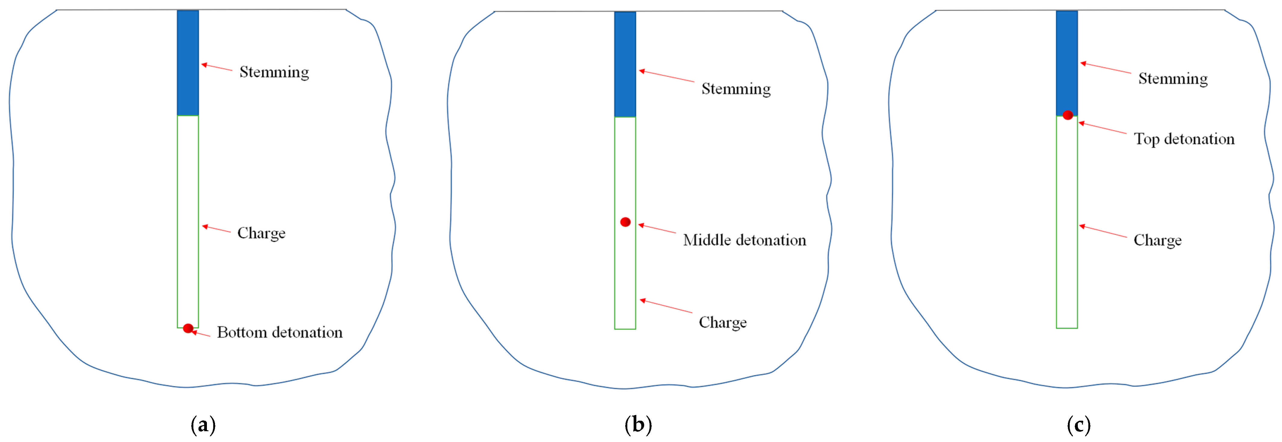
Some researchers have shown that the location of the initiation point on the blast vibration has a significant impact. Studies have shown the strip packages in the detonation point after the detonation, and the blasting wave will propagate along the direction of the package axis; after a certain period of time, the entire package completes the blast. Due to the geometric properties of the packet in the blasthole and the explosive blast velocity of the finite, along the packet axis, there are time and direction effects. In engineering practice, there is general use of top detonation, bottom detonation, and midpoint detonation. The top detonation of the initiation point is located in the mouth of the blasthole, and for the lower part of the blasthole, the rock fragmentation effect is better. However, due to the proximity of the upper free surface, if the blasting process is not yet over, there is a weak reflection of the tensile stress wave, the resulting fissure allows for the escape of blasting gas to create a channel, and the strength of the reflected wave is not enough to break the rock, making it easy to form a large piece of rock. The bottom detonation of the initiation point is located at the bottom of the blasthole, and due to the full effect of the reflected tensile stress waves, the upper part of the blasthole rock damage is wider, which is more effective, but the bottom of the blasthole rock fragmentation effect is poor. The midpoint initiation point is located in the middle of the package, as the upper and lower rocks have a good fragmentation effect; therefore, there is destruction of a more uniform area, but its damage range is smaller. From the simulation results, we know that the location of the initiation point determines the propagation direction of the blasting wave, which causes different blasting vibration responses [38]. In this study, bottom detonation, midpoint detonation, and top detonation were simulated, and we analyzed the effect of the location of the initiation point on the damage evolution process and impact damage range. The initiation locations are shown in Figure 2.

2.4. Numerical Result

2.4.1. Bottom Detonation

When the charge was detonated at the bottom of the blasthole, the detonation wave produced propagated from the bottom to the top along the blasthole, and the stress wavefront formed by the detonation wave propagated rapidly to the other end of the charge as a cone. The shock wave generated post-detonation was able to strengthen the stress field that had been formed due to the earlier detonation, resulting in a stress superposition effect on the upper rock mass [39], and then a high-stress zone and a high-energy zone formed, so the damage range of the rock in the direction of stress wave propagation was relatively large, as shown in Figure 3a,b.
With the propagation and superposition of the stress wave, a fierce reflected wave was produced when the stress wave encountered the free surface. Therefore, the damage to the rock at the top was mainly tensile damage due to the tensile stress caused by the reflected wave. As seen in Figure 3c–e, although the stress level at the top was slightly higher than that at the bottom, the damage extent at the top was larger. This is conducive to breaking the rock near the blasthole. For the rock at the bottom of the hole, the damage range is smaller than that of the blasting at the top.
Below the blasthole, the stress wave propagation attenuation was fast, so compression and shear damage to the rock was less. However, due to the low tensile strength of the rock, a large range of tensile damage still occurred below the detonation point, as shown in Figure 3f. The detonation at the bottom of the blasthole is characterized by a high residual ridge after the blasting.

2.4.2. Midpoint Detonation

The rock damage mode using midpoint detonation was obviously different. The shock wave and stress wave propagate from the middle to the top and the bottom in two directions from the blasthole. As the subsequent explosives were continuously detonated, the corresponding stress waves were also superimposed in two different directions, which caused the formation of two high-energy regions at the upper and bottom parts of the blasthole, respectively. Eventually, the damage range at the mouth and the bottom of the blasthole was large, and the shape of their damage areas was similar, as shown in Figure 4. The results showed that the midpoint detonation method is beneficial to the fragmentation of rock at the mouth and the bottom of the blasthole [40].

2.4.3. Top Detonation

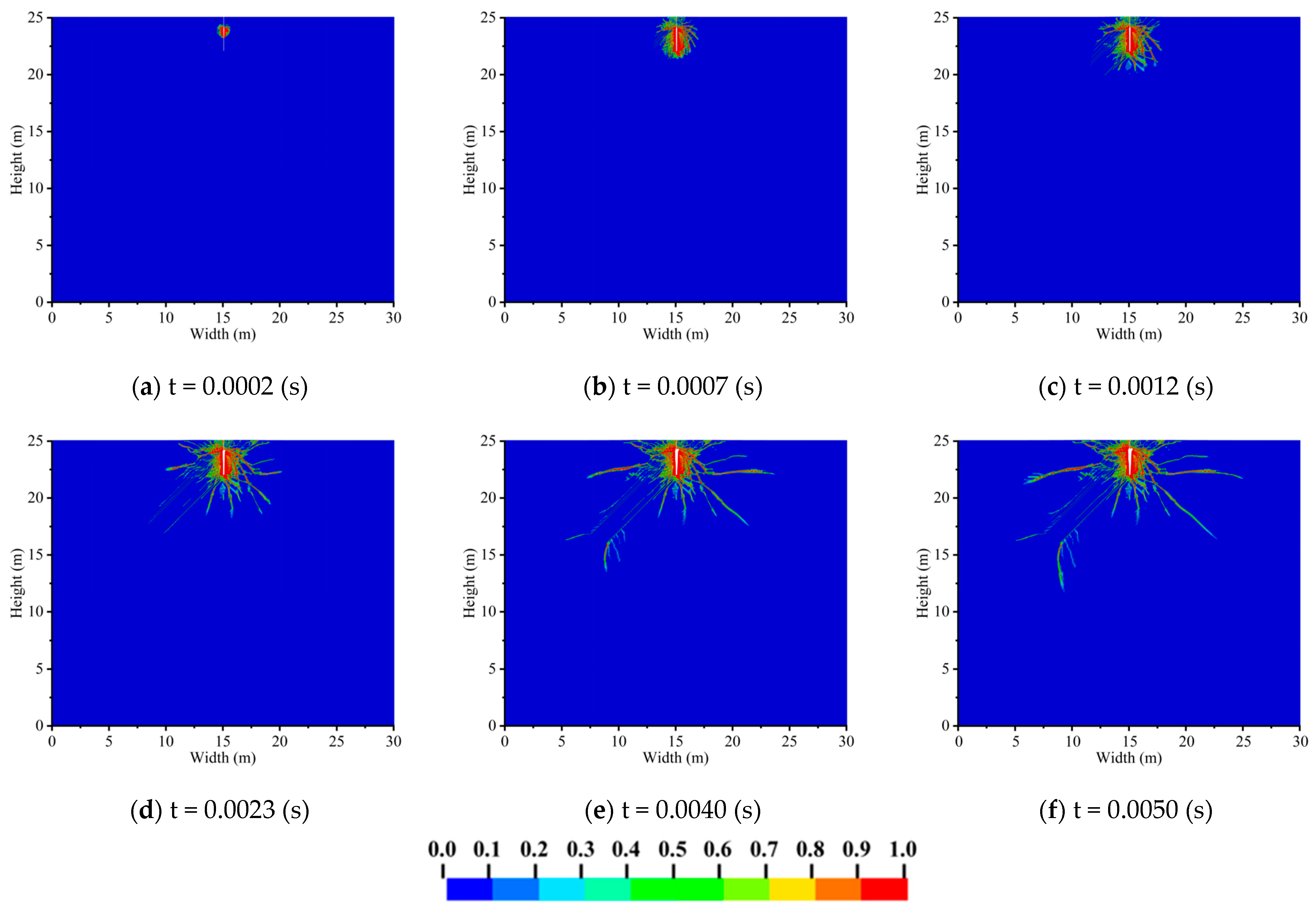
When the charge was detonated at the top of the blasthole, the shock wave and stress wave propagated from the top to the bottom and a high-energy region appeared at the bottom of this blasthole. From the beginning of the damage evolution process (Figure 5a) to the end (Figure 5e), the damaged area gradually formed an inverted funnel shape, and the rock at the bottom of the blasthole was subjected to a stronger collapsing load while the compression damage around the hole was obviously less and mainly in the form of shear damage and tensile damage, which was prone to large rock masses [41]. Using this detonation method, the damage at the hole mouth was not sufficient and there was a great possibility of leaving large rock masses. The damage to the rock at the bottom of the hole was too large and therefore not easy to handle, adding engineering safety hazards.

3. Damage Evolution Process of Layered Rock Masses

3.1. Numerical Model

The numerical simulation parameters of layered rock mass blasting are set with a blasthole diameter of 40 mm, a charge length of 2 m, and a blocked section length of 1 m. Considering the influence of the layered structure on the damage evolution process of the rock mass, layered joints with an inclination angle of 45° were set. The width of the joints was equal and the interval between the two layers was equal. The parameters of rocks, gun mud, and explosives are the same as the numerical model used above with intact rock.

3.2. Numerical Result

3.2.1. Top Detonation

When the charge was detonated at the top of the blasthole (Figure 6), the blasting high-energy zone and high-stress zone appeared at the bottom of the hole, and when the stress wave arrived at the joint, part of that was reflected and absorbed; therefore, the energy of the stress wave attenuated rapidly and damage parallel to the joint appeared on the side facing the wavefront. When the stress wave propagated from the bottom of the blasthole, the reflected tensile wave was generated along the wavefront of the joint surface and propagated downward along the joint’s inclined plane, inducing damage and failure depth of the rock mass greater than that of the intact rock mass. However, the damage range in the horizontal direction was smaller than that of the intact rock because the joint absorbed part of the energy of the stress wave; therefore, the damage was mainly distributed in the layered rock where the blasthole was located and the rock layer near the blasthole.

3.2.2. Midpoint Detonation

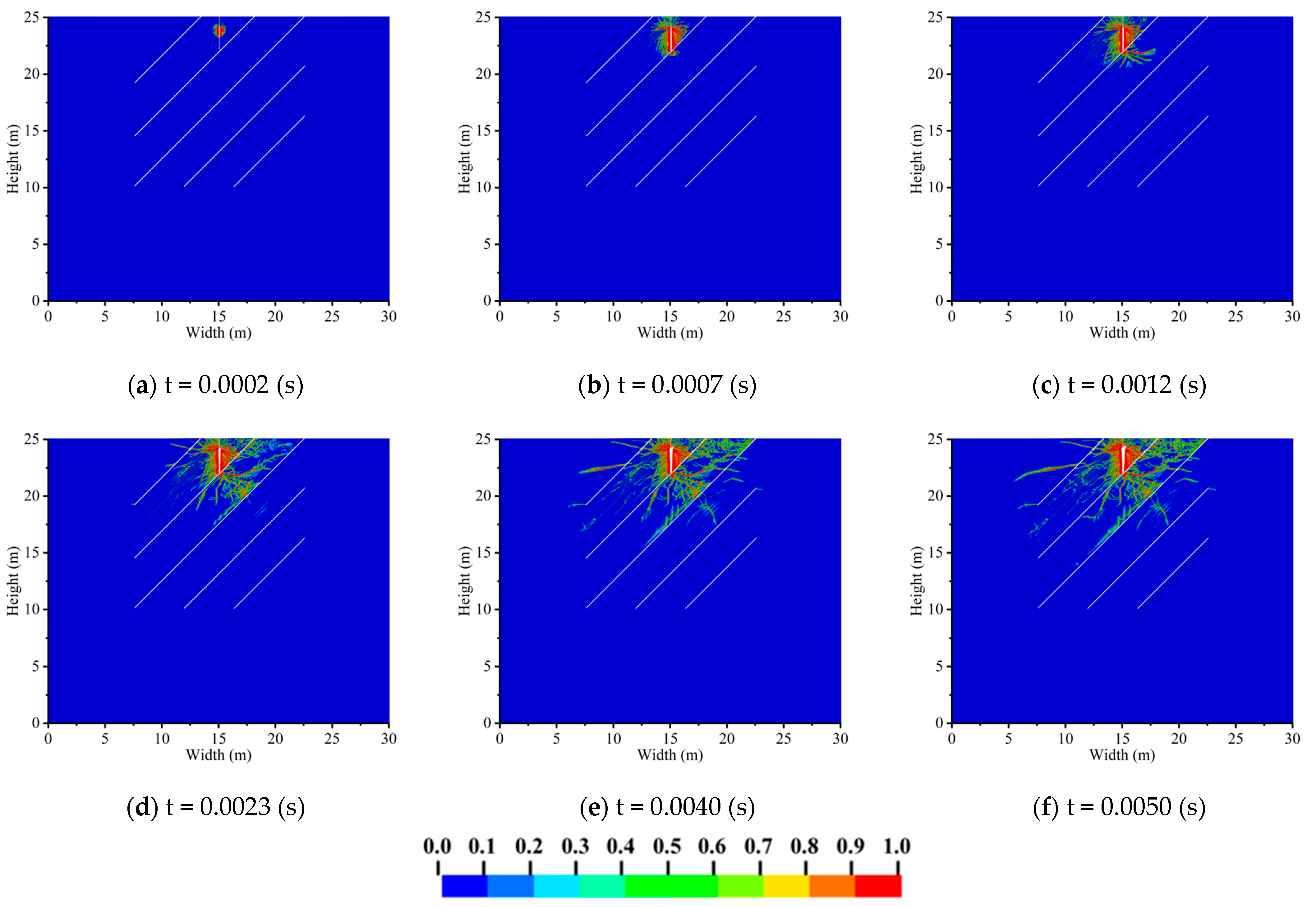
When the charge was detonated in the middle of the blasthole (Figure 7), the shock wave and stress wave were transmitted simultaneously from the initiation point to the top or bottom. There was stress and energy reinforcement in the hole mouth and hole bottom. The depth of damage to the rock mass below the blasthole was greater than that of the intact rock, and the damage along the joint was exacerbated because the rock mass near the joint surface was subjected to the reflected tensile wave; therefore, the damage range in the rock at the hole mouth was greater than that of the rock mass with detonation at the top of the blasthole.

3.2.3. Bottom Detonation

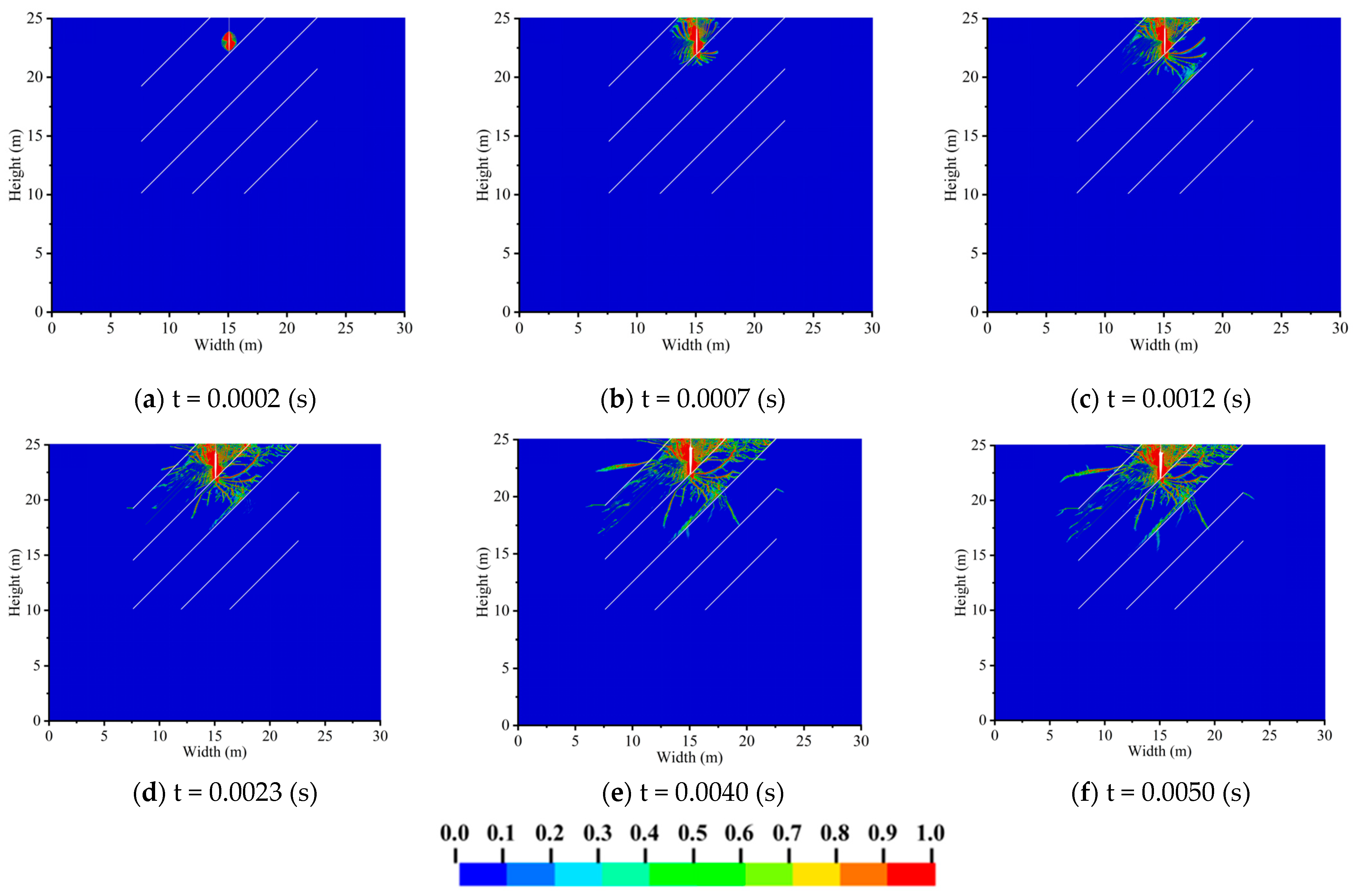
When the charge was detonated at the bottom of the blasthole (Figure 8), the damage range of the rock mass at the bottom of the blasthole was smaller than that of the rock mass at the top of the blasthole. The shock wave and stress wave were transmitted upward, resulting in stress wave superposition at the upper rock mass. Then, high-stress and high-energy zones were produced, so the damage extent to the rock mass at the top of the blasthole was larger than that of the rock mass at the bottom of the blasthole. Regarding the section near the mouth of the blasthole, the damage range of the rock mass became bigger than that of the rock mass using detonation at the top of the blasthole. For the section near the bottom of the hole, the damage range of rock mass was smaller than that of the rock mass using midpoint detonation in the blasthole; specifically, the damage in the rock layer close to the blasthole was much smaller.

4. Result and Discussion

4.1. The Effect of Location of Initiation Points

Figure 9 shows that the damage to the rock mass without layers was subjected to different blasting loads according to the different locations of the initiation point. Figure 9a shows top detonation, Figure 9b shows midpoint detonation, and Figure 9c shows bottom detonation. In the three kinds of blasting methods, top detonation showed the most serious damage to rock mass at the blasthole bottom, which means the overbreak phenomenon is easily caused, causing inconvenience regarding the later engineering treatment of rock mass at the bottom of the blasthole. Although both the bottom and middle initiation have a good fragmentation effect on the upper part of the blasthole, the damaging effect on the rock mass in the middle of the blasthole is poor because the stress wave propagated upward and downward along two different directions from the blasthole. Initiation in the bottom has a good effect on the fragmentation of the rock mass. This blasting method makes full use of the energy generated by the blasting to break the upper rock mass and obtain a better blasting effect.
As for top initiation, a high stress concentration and high-energy zone appear at the bottom, inducing a larger damage extent at the bottom, which is conducive to improving the fragmentation of the rock mass at the bottom. For middle initiation, a high-stress-concentration area and high-energy area occur at the upper and bottom parts, so fragmentation of the upper and bottom rock masses is enhanced and the damage and destruction to the rock masses around the blasthole are more uniform. For bottom initiation, the high stress concentration and high-energy area are concentrated at the top, which is conducive to boosting the fragmentation effect of the orifice of the blasthole and better forming the throwing crater.
Utilizing MATLAB software (R2022b), we have developed a program that calculates the damaged area of intact rock at different time points using different locations of initiation points. The results are presented in Table 3 and illustrated in Figure 10.
Table 3 and Figure 10 indicate that following the detonation of intact rock, midpoint initiation exhibits the best fragmentation effect, with the damaged area reaching up to 1.17 m2. Both the top and bottom initiations yield similar results, producing approximately 0.10% of the damaged range. As the blasting stress wave further expands, the damaged area from the midpoint initiation consistently exceeds that of the other two initiation positions. Moreover, the growth trend of the damaged area from the midpoint initiation is relatively stable, reaching 17.28 m2 at the end of the blasting stress wave action (at 5 ms), which accounts for 2.30% of the total area. The initial fragmentation effect of the top initiation is slightly better than that of the bottom initiation. After 0.7 ms, the damage growth trend of the top initiation slows down significantly, falling far short of the bottom initiation. At 5 ms, the bottom initiation results in a damage area 10.16% higher than that of the top initiation. For the midpoint initiation in the blasthole, the blasting stress waves propagate approximately in a “spherical” manner, distributing energy more evenly, which prolongs the duration of the damaging action and expands the range of damage, consistent with the findings of Ylitalo et al. (2021) [42].

4.2. The Effect of Joint Distribution

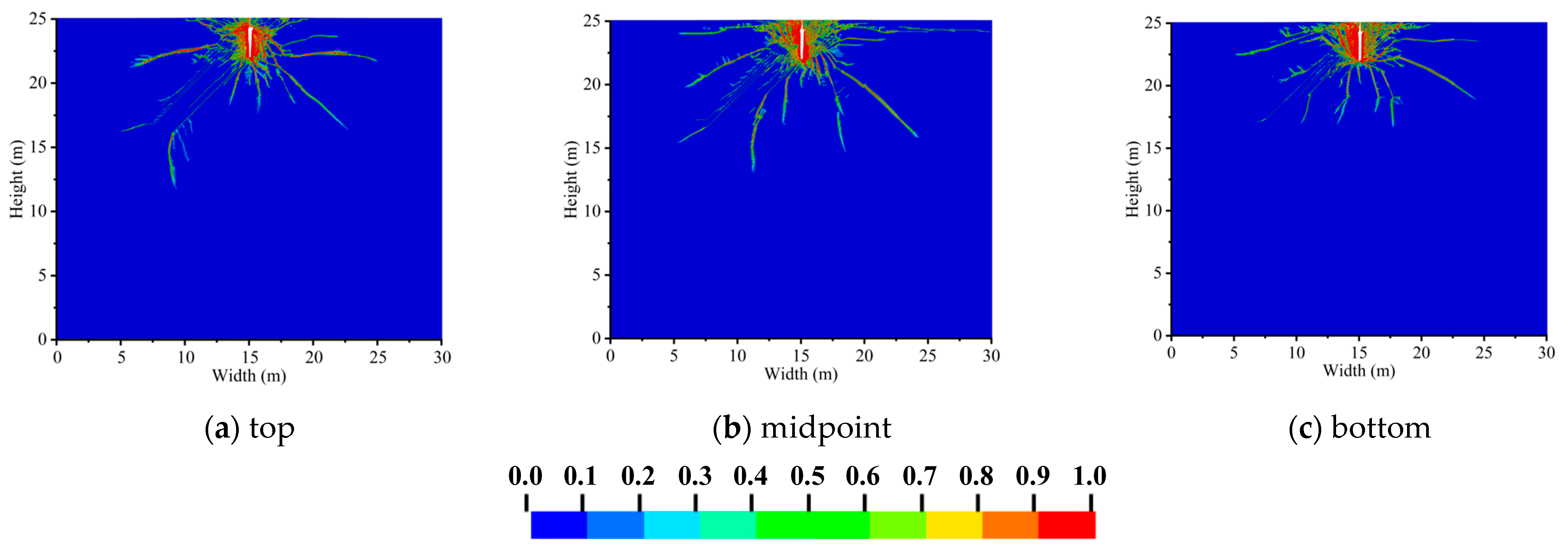
Figure 11 shows that the damage to rock mass with layered joints was subjected to blasting loads with different locations of the initiation point. Figure 11a shows top detonation, Figure 11b shows midpoint detonation, and Figure 11c shows bottom detonation. When there are layered joints, due to the different wave impedances, multiple reflections and transmissions will occur on the upstream and downstream surfaces of multiple layered joints, changing the propagation path of the stress wave, causing the energy carried by the stress wave to dissipate, thus leading to the asymmetry of the damage distribution. In the layered rock near the blasting source, the damage to the rock mass at the bottom of the blasthole is mainly concentrated in the rock mass less than 90° away from the direction of the vertical layered fractures.
In the direction parallel to the layered fracture, due to the reflected tensile wave generated by the reflection of the stress wave and the stress concentration on the discontinuous surface, the rock mass corresponding to the upstream surface of the fracture has a strengthening effect on the rock mass fragmentation, and a large number of damage cracks are distributed. In the normal direction of the layered joints, due to the transmission and reflection of the stress wave, the energy is dissipated, and the shielding effect of the layered joints on the damage is shown on the downstream surface of the fracture [43,44]. This phenomenon has a very important application value in protection engineering. It can make full use of the shielding effect of the layered joints on the stress wave to reduce the damaging effect of external blasting waves on the protection structure, so as to ensure the safety and stability of the protection structure.
In layered-joint rock mass, in addition to changing the asymmetry of the damage distribution due to the influence of layered joints, it is also affected by the initiation method, which causes the stress waves to superpose in different directions along the blasthole, thus affecting the distribution of high-stress and high-energy zones in the rock mass around the blasthole. Moving up along the initiation position, the damage at the bottom of the blasthole is more serious. With the upward movement of the initiation position, both the bottom and middle initiation show a good fragmentation effect on the upper part of the blasthole, while the bottom initiation shows relatively uniform damage and destruction effects on the rock mass around the blasthole. This shows that in an actual blasting project, when encountering layered jointed rock mass for blasting, the location relationship between the blasting hole layout and the jointed structure, as well as a reasonable blasting method, should be considered so as to obtain a better rock fragmentation effect.
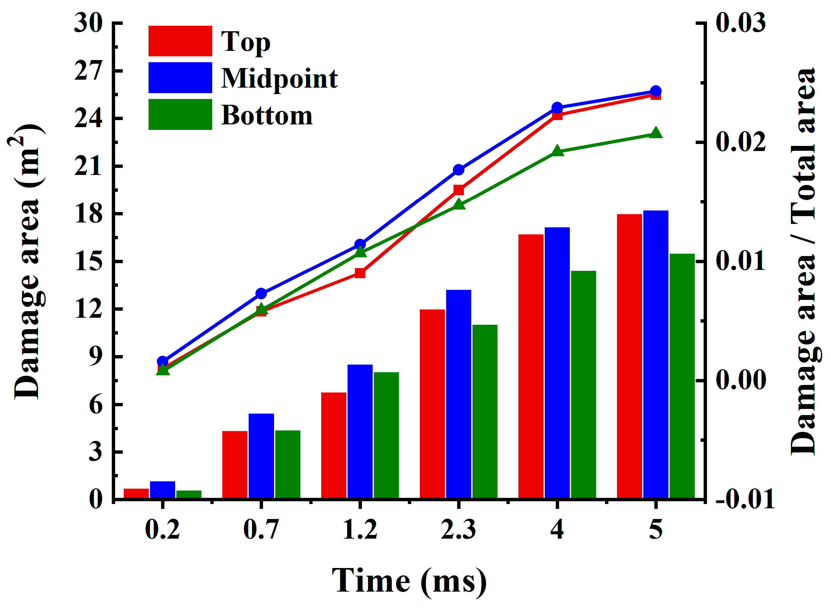
Table 4 and Figure 12 display the damage area and proportion at different time points under different locations of initiation points with layered joints.
Table 4 and Figure 12 show that in a rock mass with layered joints, midpoint initiation results in the widest damage range, with an area of 18.23 m2, and the damage increment is relatively uniform post-detonation. Both the top and bottom initiations exhibit nearly identical fragmentation effects within 0.7 ms after detonation, causing damage areas of 4.36 m2 and 4.40 m2, respectively. With the propagation of the blasting stress wave and the expansion of the blasting gas, the fragmentation effect of the top initiation significantly diminishes, with the damaged area indicating a lower degree of damage by approximately 15.88% compared to the bottom initiation. Conversely, during the subsequent blasting process, the top initiation causes more pronounced damage to the rock, with an increased rate of damage growth, ultimately reaching a damaged area of 18.01 m2, slightly less than the midpoint initiation and significantly exceeding the bottom initiation of 15.51 m2 by 16.12%. For the top initiation, the blasting stress wave propagates downward, interacting with a broader contact surface of the stratified joints, resulting in the most effective reflection and tensile action. Rocks are more resistant to compression than tension, and under the action of the reflected tensile stress wave, the rate of damage increases, leading to a higher degree of damage.
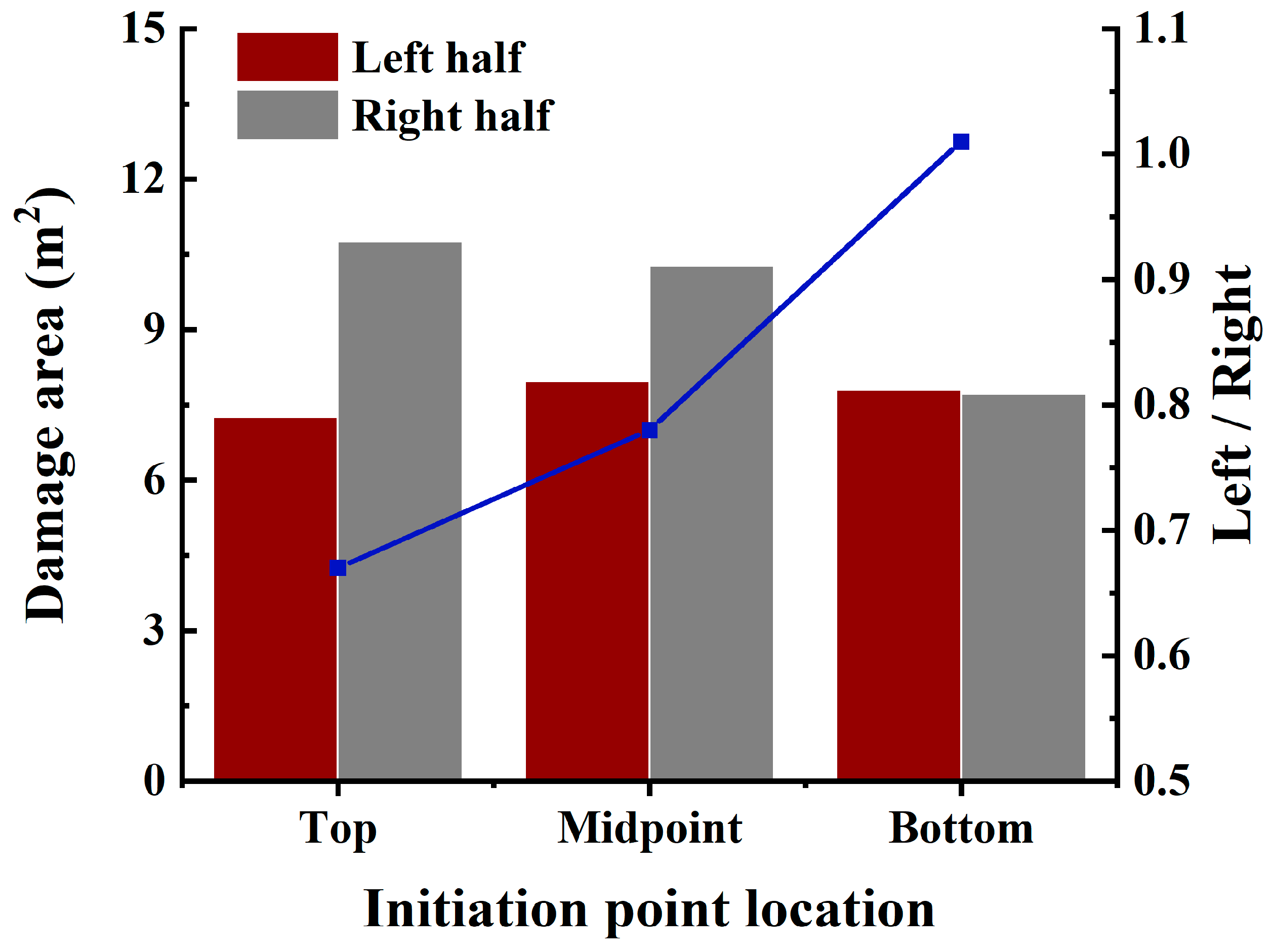
Figure 13 illustrates the damage areas on the left and right halves of the blasthole for different initiation points, as well as the ratio between the two. Under both top and midpoint initiations, the damage area on the left half is approximately 7.5 m2, significantly less than the 10.5 m2 on the right half. For bottom initiation, the damage areas on both sides of the blasthole are approximately 7.7 m2. Considering the ratio of damage areas on both sides of the blasthole, the top initiation has a ratio of 0.67, which is lower than 0.78 for midpoint initiation, indicating greater asymmetry in the damage distribution for top initiation. The bottom initiation exhibits the most uniform damage distribution, with a ratio of 1.01. The layered joints are oriented at a counterclockwise 45° angle to the horizontal axis, located below the blasthole, and are able to fully interact with the downward-propagating blasting stress wave during top initiation, resulting in reflective tensile actions that concentrate damage primarily in the normal direction of the layered joints. With midpoint initiation, only a portion of the stress wave propagates downward, while with bottom initiation, the stress wave propagates upward, leading to a more symmetrical damage distribution.
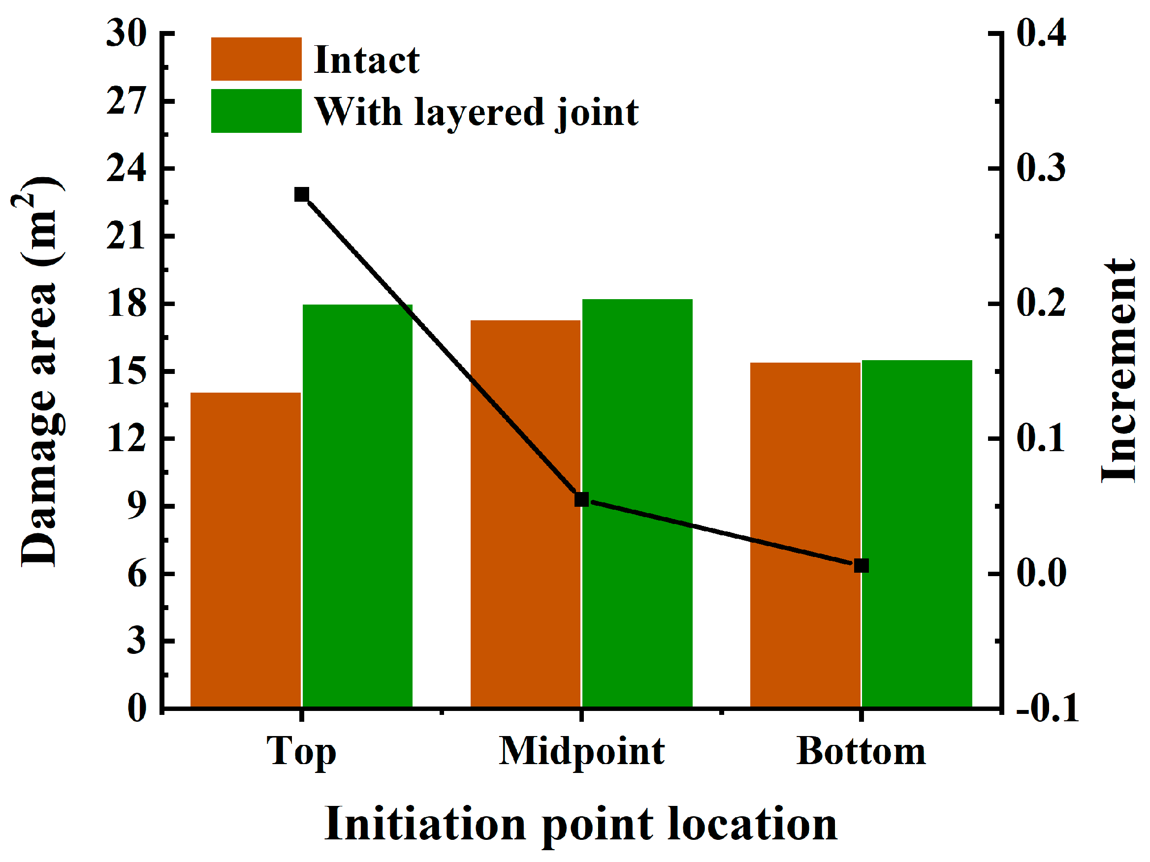
Figure 14 shows the damage areas and their corresponding increments for intact rock and rock with layered joints at different initiation points. For top initiation, the presence of layered joints significantly enhances the blasting fragmentation effect, improving it by 28.09% compared to intact rock. The distribution of layered joints has a certain impact on the fragmentation effect of midpoint initiation, with the damaged area increasing from 17.28 m2 for intact rock to 18.23 m2. With bottom initiation, the damaged areas of the two types of rock differ by only 0.59%.

5. Conclusions

In this paper, through theoretical analysis, numerical simulation, and a comparative analysis of different locations of initiation points and the joints on the damage extent of rock masses, the following conclusions are drawn:
(1)
The nature of the effect of the initiation point location on the rock-fragmentation efficiency is that the initiation methods influence the stress concentration and high-energy distribution of rock mass under blasting. The superposition among the stress waves in the blasthole has a certain impact on the damage range of the rock mass.
(2)
Top detonation shows the most serious damage to rock mass at the blasthole bottom, the damaging effect to the rock mass in the middle of the blasthole is poor using the middle initiation method, and the initiation in the bottom has a good effect on the fragmentation to rock mass.
(3)
Due to the existence of joints, rock damage under blasting load shows a non-symmetrical distribution. A series of complex transmission and reflection processes occur when the stress wave propagates to the upstream surface of the multiple-layered joints, which intensifies the rock damage on the upstream surface. Furthermore, the damage to rock mass on the downstream surfaces of multiple layered joints is obviously weakened. The joints have a certain shielding effect on the blasting stress wave propagation for the rock on the back side of the joints.
The conclusions drawn from this study are of significant importance for a deeper understanding of the mechanisms of rock fragmentation in blasting and to better assess the blasting fragmentation effects in rock masses with layered joints. They provide a theoretical basis for the optimization of blasting parameter design. In addition, there are some limitations in this study; although the use of plane strain modeling can obtain better numerical results while saving computer resources, the influence produced by geometric effects still cannot be neglected.

Author Contributions

Investigation, L.W.; Data curation, D.Y.; Writing—original draft, L.X., J.Z. and H.C.; Writing—review & editing, Y.Q. All authors have read and agreed to the published version of the manuscript.

Funding

This work was supported by the Program of National Natural Science Foundation of China (52074262); Fundamental Research Funds for the Central Universities (2020QN06); State Key Laboratory of Precision Blasting and Hubei Key Laboratory of Blasting Engineering, Jianghan University (PBSKL2023A7); and Undergraduate Training Program for Innovation and Entrepreneurship China University of Mining and Technology (202310290022Z).

Data Availability Statement

The original contributions presented in the study are included in the article, further inquiries can be directed to the corresponding author.

Conflicts of Interest

The authors declare no conflicts of interest.

References

  1. Mosinets, V.N.; Gorbacheva, N.P. A seismological method of determining the parameters of the zones of deformation of rock by blasting. Sov. Min. 1972, 8, 640–647. [Google Scholar] [CrossRef]
  2. Kutter, H.K.; Fairhurst, C. On the fracture process in blasting. Int. J. Rock Mech. Min. Sci. 1971, 8, 181–202. [Google Scholar] [CrossRef]
  3. Brinkmann, J.R. An experimental study of the effects of shock and gas penetration in blasting. In Proceedings of the 3rd International Symposium on Rock Fragmentation by Blasting, Brisbane, Australia, 26–31 August 1990. [Google Scholar]
  4. Daehnke, A.; Rossmanith, H.P.; Napier, J.A.L. Gas pressurisation of blast-induced conical cracks. Int. J. Rock Mech. Min. Sci. 1997, 34, 263.e1–263.e17. [Google Scholar] [CrossRef]
  5. Cho, S.H.; Kaneko, K. Influence of the applied pressure waveform on the dynamic fracture processes in rock. Int. J. Rock Mech. Min. Sci. 2004, 41, 771–784. [Google Scholar] [CrossRef]
  6. Zhu, Z.M.; Xie, H.P.; Mohanty, B. Numerical investigation of blasting-induced damage in cylindrical rocks. Int. J. Rock Mech. Min. Sci. 2008, 45, 111–121. [Google Scholar] [CrossRef]
  7. Yang, R.S.; Wang, Y.B.; Xue, H.J.; Wang, M.Y. Dynamic behavior analysis of perforated crack propagation in two-hole blasting. Procedia Earth Planet. Sci. 2012, 5, 254–261. [Google Scholar]
  8. Yang, R.S.; Ding, C.X.; Yang, L.Y.; Lei, Z.; Zhang, Z.; Wang, Y. Visualizing the blast-induced stress wave and blasting gas action effects using digital image correlation. Int. J. Rock Mech. Min. Sci. 2018, 112, 47–54. [Google Scholar] [CrossRef]
  9. Xie, L.X.; Lu, W.B.; Zhang, Q.B.; Jiang, Q.H.; Chen, M.; Zhao, J. Analysis of damage mechanisms and optimization of cut blasting design under high in-situ stresses. Tunn. Undergr. Space Technol. 2017, 66, 19–33. [Google Scholar] [CrossRef]
  10. Mahdi, S.F.; Cagri, G.; Zhou, M.L.; Kordestani, H.; Muho, E.V. Estimation of Damage Induced by Single-Hole Rock Blasting: A Review on Analytical, Numerical, and Experimental Solutions. Energies 2020, 14, 29. [Google Scholar] [CrossRef]
  11. Qiu, P.; Yue, Z.W.; Yang, R.S.; Ju, Y. Modified mixed-mode caustics interpretation to study a running crack subjected to obliquely incident blast stress waves. Int. J. Impact Eng. 2021, 150, 103821. [Google Scholar] [CrossRef]
  12. Li, X.D.; Liu, K.W.; Sha, Y.Y.; Yang, J.; Ma, S.; Hong, Z. Investigation on radial fracturing around blasthole under combined static stress and blasting. Theor. Appl. Fract. Mech. 2023, 127, 104038. [Google Scholar] [CrossRef]
  13. Li, N.; Zhang, P.; Duan, Q.W.; Swoboda, G. Dynamic damage model of the rock mass medium with microjoints. Int. J. Damage Mech. 2003, 12, 163–173. [Google Scholar]
  14. Lin, Q.B.; Cao, P.; Meng, J.J. Strength and failure characteristics of jointed rock mass with double circular holes under uniaxial compression: Insights from discrete element method modelling. Theor. Appl. Fract. Mech. 2020, 109, 102692. [Google Scholar] [CrossRef]
  15. Huang, J.; Chen, S.H.; Liu, M.L.; Li, K.P. Physical model test and numerical simulation study of cumulative damage to deep tunnel surrounding rock under cyclic blasting load. Int. J. Damage Mech. 2023, 32, 161–184. [Google Scholar] [CrossRef]
  16. Rossmanith, H.P. Fracture and damage of concrete and rock. In Proceedings of the Second International Conference on Fracture and Damage of Concrete and Rock, Vienna, Austria, 9–13 November 1992. [Google Scholar]
  17. Wu, L.; Chen, J.P. Study on Smooth-Blasting Results in Jointed and Fractured Rock. J. China Univ. Geosci. 2001, 12, 145–149. [Google Scholar]
  18. Li, H.B.; Xia, X.; Li, J.C.; Jian, Z.; Bo, L.; Yaqun, L. Rock damage control in bedrock blasting excavation for a nuclear power plant. Int. J. Rock Mech. Min. Sci. 2011, 48, 210–218. [Google Scholar]
  19. Li, J.C.; Li, H.B.; Zhao, J. An improved equivalent viscoelastic medium method for wave propagation across layered rock masses. Int. J. Rock Mech. Min. Sci. 2015, 73, 62–69. [Google Scholar] [CrossRef]
  20. Fan, L.F.; Wang, L.J.; Wu, Z.J. An investigation of propagation direction induced difference of transmission coefficient in complex rock mass. Int. J. Rock Mech. Min. Sci. 2020, 135, 104504. [Google Scholar] [CrossRef]
  21. Guo, X.; Ding, C.X.; Wei, P.J.; Yang, R.S. Theoretical analysis of the interaction between blasting stress wave and linear interface crack under high in-situ stress in deep rock mass. Int. J. Rock Mech. Min. Sci. 2024, 176, 105723. [Google Scholar] [CrossRef]
  22. Chen, X.; Li, J.C.; Cai, M.F.; Zou, Y.; Zhao, J. Experimental study on wave propagation across a rock joint with rough surface. Rock Mech. Rock Eng. 2015, 48, 2225–2234. [Google Scholar] [CrossRef]
  23. Zou, Y.; Li, J.C.; Zhao, J. A novel experimental method to investigate the seismic response of rock joints under obliquely incident wave. Rock Mech. Rock Eng. 2019, 52, 3459–3466. [Google Scholar] [CrossRef]
  24. Liu, Y.; Lu, C.P.; Liu, B.; Zhang, H.; Wang, H.Y. Experimental and field investigations on seismic response of joints and beddings in rocks. Ultrasonics 2019, 97, 46–56. [Google Scholar] [CrossRef]
  25. Xia, Y.J.; Zhang, C.Q.; Zhou, H.; Chen, J.; Gao, Y.; Liu, N.; Chen, P. Structural characteristics of columnar jointed basalt in drainage tunnel of Baihetan hydropower station and its influence on the behavior of P-wave anisotropy. Eng. Geol. 2020, 264, 105304. [Google Scholar] [CrossRef]
  26. Han, Z.Y.; Li, D.Y.; Zhou, T.; Zhu, Q.; Ranjith, P.G. Experimental study of stress wave propagation and energy characteristics across rock specimens containing cemented mortar joint with various thicknesses. Int. J. Rock Mech. Min. Sci. 2020, 131, 104352. [Google Scholar] [CrossRef]
  27. Li, Y.S.; Zhu, J.B.; Han, D.Y.; Zhao, R.; Ma, Y.; Zhou, T. Experimental study of the dynamic responses of surrounding jointed rock masses and adjacent underground openings and induced ground vibrations subjected to underground explosion. Tunn. Undergr. Space Technol. 2023, 135, 105060. [Google Scholar] [CrossRef]
  28. Zhang, Y.T.; Yang, R.S.; Chen, C.; Li, C.; Luo, H. Analysis of the blasting effect of strip cartridge position on jointed rock mass. Mech. Adv. Mater. Struct. 2023, 30, 1249–1259. [Google Scholar] [CrossRef]
  29. Wang, Q.R.; Song, E.X.; Xu, P.; He, Y.; Shi, X.; Xie, H. Dynamic Performance and Stress Wave Propagation Characteristics of Parallel Jointed Rock Mass Using the SHPB Technique. KSCE J. Civ. Eng. 2023, 27, 2275–2286. [Google Scholar] [CrossRef]
  30. Lu, H.; Pan, Y.; He, K.; Wang, F.; Gao, L.; Pu, S.; Li, E. Dynamic Mechanical Properties and Damage Evolution Characteristics of Beishan Deep Granite under Medium and High Strain Rates. Materials 2023, 16, 5235. [Google Scholar] [CrossRef]
  31. Li, Z.; Hu, Y.; Wang, G.Z.; Zhou, M.; Hu, W.; Zhang, X.; Gao, W. Study on cyclic blasting failure characteristics and cumulative damage evolution law of tunnel rock mass under initial in-situ stress. Eng. Fail. Anal. 2023, 150, 107310. [Google Scholar] [CrossRef]
  32. Li, X.F.; Zhang, Q.B.; Li, H.B.; Zhao, j. Grain-Based Discrete Element Method (GB-DEM) Modelling of Multi-scale Fracturing in Rocks Under Dynamic Loading. Rock Mech. Rock Eng. 2018, 52, 3785–3817. [Google Scholar] [CrossRef]
  33. Lak, M.; Marji, M.F.; Bafghi, A.Y.; Abdollahipour, A. Analytical and numerical modeling of rock blasting operations using a two-dimensional elasto-dynamic Green’s function. Int. J. Rock Mech. Min. Sci. 2019, 114, 208–217. [Google Scholar] [CrossRef]
  34. Luo, Y.; Wang, G.; Li, X.P.; Liu, T.; Mandal, A.K.; Xu, M.; Xu, K. Analysis of energy dissipation and crack evolution law of sandstone under impact load. Int. J. Rock Mech. Min. Sci. 2020, 132, 104359. [Google Scholar] [CrossRef]
  35. Dong, Q.; Li, X.P.; Jia, Y.S.; Sun, J.S. A Numerical Simulation of Blasting Stress Wave Propagation in a Jointed Rock Mass under Initial Stresses. Appl. Sci. 2021, 11, 7873. [Google Scholar] [CrossRef]
  36. Hu, H.N.; Yang, L.Y.; Feng, C.; Zhu, X.; Zhou, J.; Liu, X. Development of BB model and investigation of P-wave propagation across jointed rock masses using CDEM. Comput. Geotech. 2024, 165, 105910. [Google Scholar] [CrossRef]
  37. Banadaki, D.M.M. Stress-Wave Induced Fracture in Rock due to Explosive Action. Ph.D. Thesis, University of Toronto, Toronto, ON, Canada, 2010. [Google Scholar]
  38. Gao, Q.D.; Lu, W.B.; Yan, P.; Hu, H.; Yang, Z.; Chen, M. Effect of initiation location on distribution and utilization of explosion energy during rock blasting. Bull. Eng. Geol. Environ. 2019, 78, 3433–3447. [Google Scholar] [CrossRef]
  39. Ding, C.X.; Yang, R.S.; Feng, C. Stress wave superposition effect and crack initiation mechanism between two adjacent bore-holes. Int. J. Rock Mech. Min. Sci. 2021, 138, 104622. [Google Scholar] [CrossRef]
  40. Fan, Y.; Niu, H.C.; Yang, G.D.; Gao, Q.; Wu, J.; Tian, B. Near-field vibration induced by single-hole blasting under different initiation modes. Eu-Ropean J. Environ. Civ. Eng. 2024, 28, 753–778. [Google Scholar] [CrossRef]
  41. Leng, Z.D.; Sun, J.S.; Lu, W.B.; Xie, X.; Jia, Y.; Zhou, G.; Chen, M. Mechanism of the in-hole detonation wave interactions in dual initiation with electronic detonators in bench blasting operation. Comput. Geotech. 2021, 129, 103873. [Google Scholar] [CrossRef]
  42. Ylitalo, R.M.; Zhang, Z.X.; Bergstro, P. Effect of detonator position on rock fragmentation: Full-scale field tests at Kevitsa open pit mine. Int. J. Rock Mech. Min. Sci. 2021, 147, 104918. [Google Scholar] [CrossRef]
  43. Li, D.Y.; Han, Z.Y.; Zhu, Q.Q.; Zhang, Y.; Ranjith, P.G. Stress wave propagation and dynamic behavior of red sandstone with single bonded planar joint at various angles. Int. J. Rock Mech. Min. Sci. 2019, 117, 162–170. [Google Scholar] [CrossRef]
  44. Ma, K.; Peng, Y.L.; Liao, Z.Y.; Wang, Z.R. Dynamic responses and failure characteristics of the tunnel caused by rockburst: An entire process modelling from incubation to occurrence phases. Comput. Geotech. 2024, 171, 106340. [Google Scholar] [CrossRef]
Figure 1. Diagram of the blasting hole.
Buildings 14 03227 g001
Figure 2. Three kinds of initiation point locations: (a) bottom initiation; (b) middle initiation; (c) top initiation.
Buildings 14 03227 g002
Figure 3. Schematic diagram of cross-section damage at the bottom of the blasthole.
Buildings 14 03227 g003
Figure 4. Schematic diagram of cross-section damage at the middle of the blasthole.
Buildings 14 03227 g004
Figure 5. Schematic diagram of cross-section damage at the top of the blasthole.
Buildings 14 03227 g005
Figure 6. The damage evolution of rock mass with layered joint under blasting load at top detonation.
Buildings 14 03227 g006
Figure 7. The damage evolution of rock mass with layered joint under blasting load at midpoint detonation.
Buildings 14 03227 g007
Figure 8. The damage evolution of rock mass with layered joint under blasting load at bottom detonation.
Buildings 14 03227 g008
Figure 9. Different locations of initiation points without layered joints.
Buildings 14 03227 g009
Figure 10. Damage area and proportion at different time points under different locations of initiation points without layered joint.
Buildings 14 03227 g010
Figure 11. Different locations of initiation points with layered joints.
Buildings 14 03227 g011
Figure 12. Damage area and proportion at different time points under different locations of initiation points with layered joints.
Buildings 14 03227 g012
Figure 13. Asymmetry of damage distribution under different locations of initiation points with layered joint.
Buildings 14 03227 g013
Figure 14. Comparison of damage between intact rock and rock with layered joint under different locations of initiation points.
Buildings 14 03227 g014
Table 1. Input parameters for rock (from Banadaki and Xie et al. (2010, 2017) [9,37]).
ParameterValueParameterValue
Mass density (kg/m3)2660Poisson’s ratio0.19
Elastic shear modulus (GPa)21.9Relative tensile strength 0.04
Compressive strength (MPa)167.8Relative shear strength 0.21
Table 2. Parameters of the explosive material and JWL equation of state (from Li et al. (2011) [18]).
ρ e   ( k g / m 3 ) V o D   ( m / s ) P C J   ( G P a ) A   ( G P a ) B   ( G P a ) R1R2 ω E 0   ( G P a )
130040005.2214.40.1824.20.90.154.192
Table 3. Damage area and proportion at different time points under different locations of initiation points without layered joint.
LocationTopMidpointBottom
Time (ms) Damage Area (m2)Proportion (%)Damage Area (m2)Proportion (%)Damage Area (m2)Proportion (%)
0.20.720.101.170.160.760.10
0.75.090.686.050.814.900.65
1.27.591.018.751.178.581.14
2.310.591.4112.081.6111.751.57
4.013.111.7515.952.1314.391.92
5.014.061.8717.282.3015.422.06
Table 4. Damage area and proportion at different time points under different locations of initiation points with layered joints.
LocationTopMidpointBottom
Time (ms) Damage Area (m2)Proportion (%)Damage Area (m2)Proportion (%)Damage Area (m2)Proportion (%)
0.20.720.101.170.160.590.08
0.74.360.585.440.734.400.59
1.26.780.908.531.148.061.07
2.312.001.6013.251.7711.051.47
4.016.732.2317.172.2914.431.92
5.018.012.4018.232.4315.512.07
Disclaimer/Publisher’s Note: The statements, opinions and data contained in all publications are solely those of the individual author(s) and contributor(s) and not of MDPI and/or the editor(s). MDPI and/or the editor(s) disclaim responsibility for any injury to people or property resulting from any ideas, methods, instructions or products referred to in the content.