
A New Type of Wharf and a Study of Its Mechanical Properties by FE (Finite Element) and Experimental Methods

Abstract
:1. Introduction
2. Structural Form and Methodology
2.1. Structural Assumptions
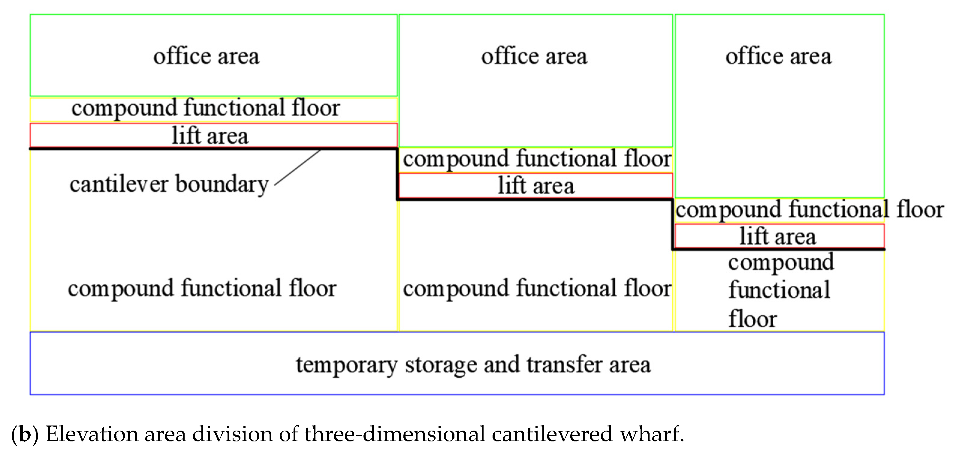
2.2. Division of Port Functional Area
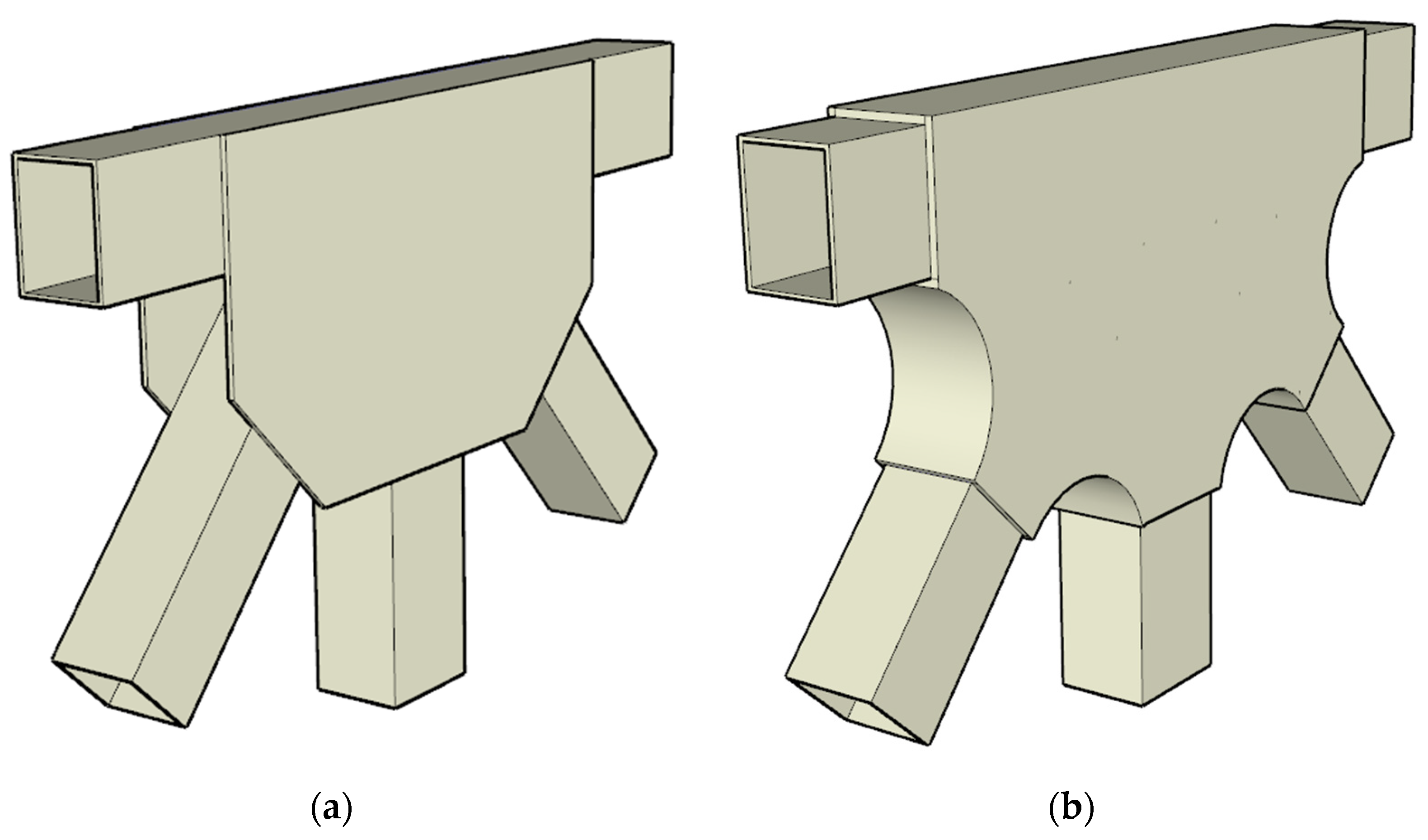
2.3. Connection of Web Member and Beam
3. Finite Element Analysis
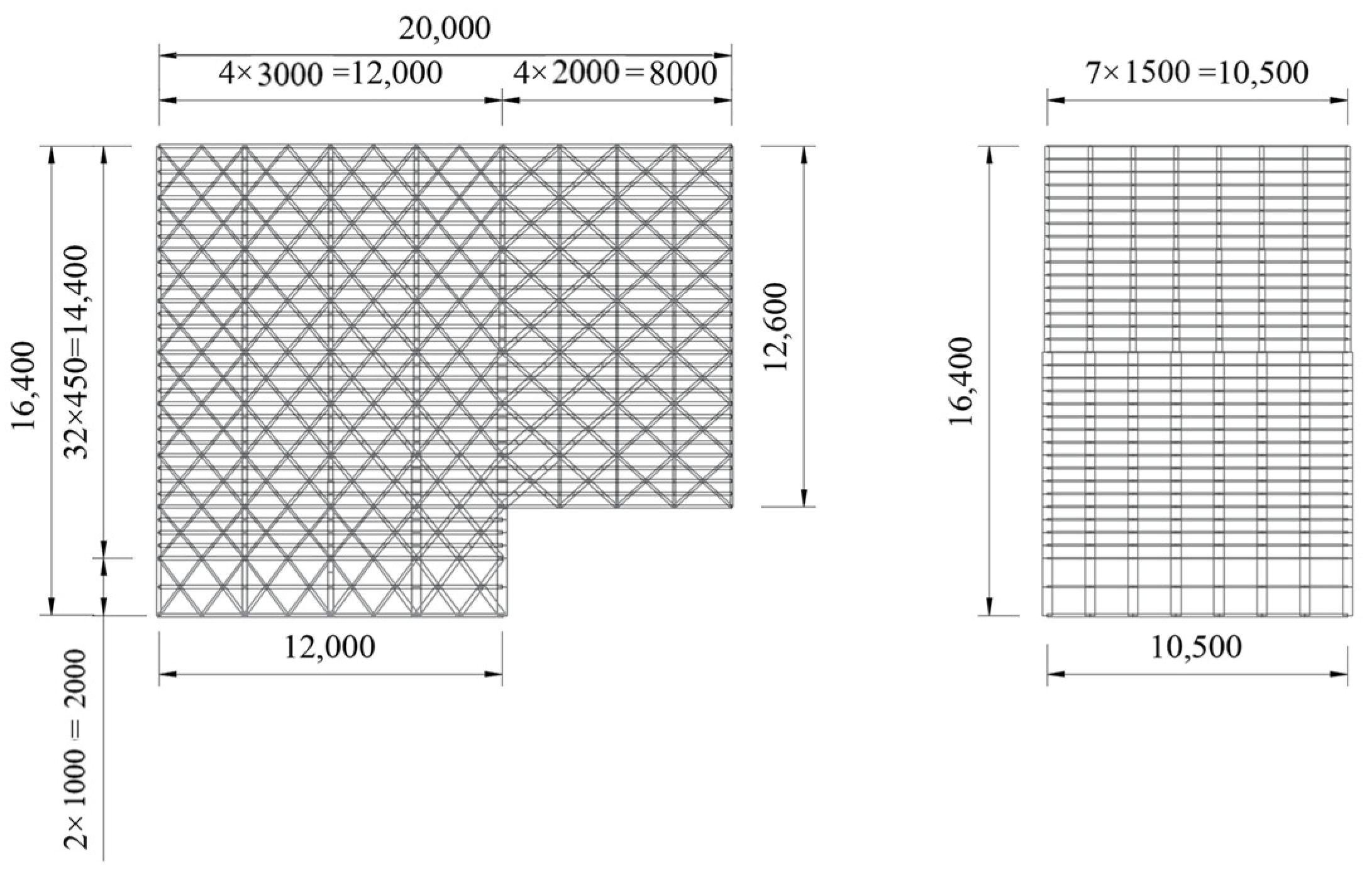
3.1. Calculation Models for Three-Dimensional Cantilevered Wharf
- Floor live load: The bottom two floors are loaded with a fully uniform distributed load of 5 kN/m2, and the rest are 3.5 kN/m2.
- Hanging load: A 40-ton hanging load is applied at the maximum cantilever length.
- Wind load: The offward wind load is 0.66 kN/m2, and the shoreline wind load is 0.16 kN/m2.
- Snow load: The uniform snow load is 0.4 kN/m2.
- Temperature effect: The initial temperature was 15 °C, which was increased by 25 °C and then decreased by 20 °C.
- Seismic load: The seismic load magnitude is 8.
- The following load combinations are used:
- -
- Combination I: 1.2 dead load + 1.4 floor live load + 0.7 hanging load + 0.6 wind load + 0.7 snow load + 0.6 temperature effect;
- -
- Combination II: dead load + 0.6 floor live load + 0.6 hanging load + 0.2 snow load + 0.4 temperature effect + seismic load;
- -
- Combination III: 1.2 dead load + 1.3 seismic load.
3.2. FEA Results
3.2.1. Analysis of Support Reaction Force, Structural Internal Force, and Stresses
- (1)
- Pile block force
- (2)
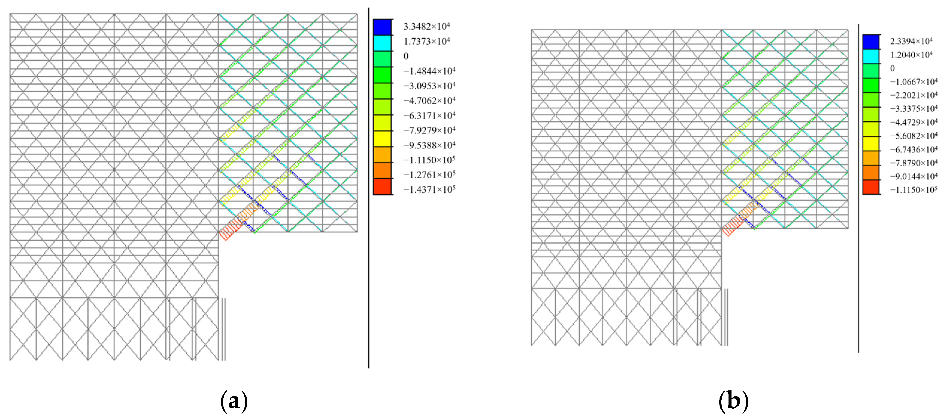
- Structural internal force
- (3)
- Structural stresses
- (4)
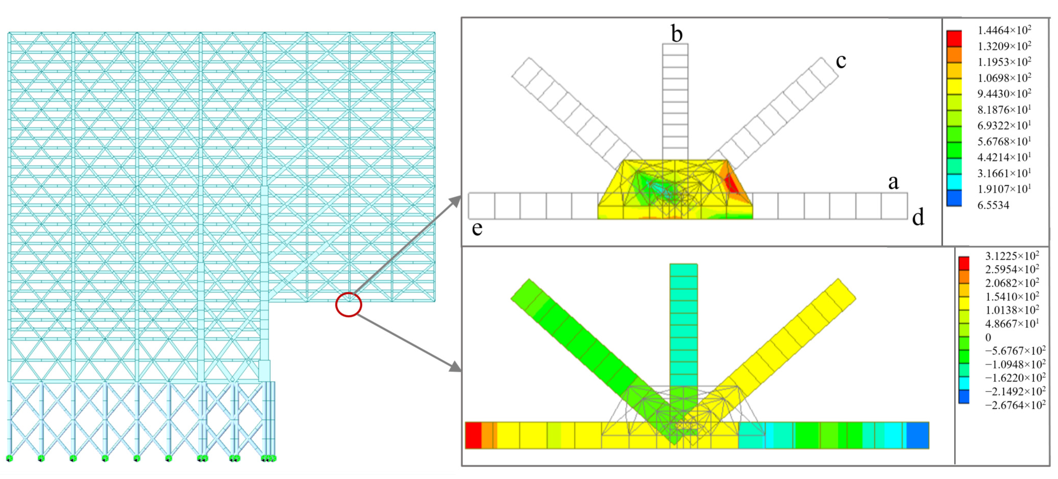
- Stress analysis of joint connections
3.2.2. Analysis of Structural Stiffness
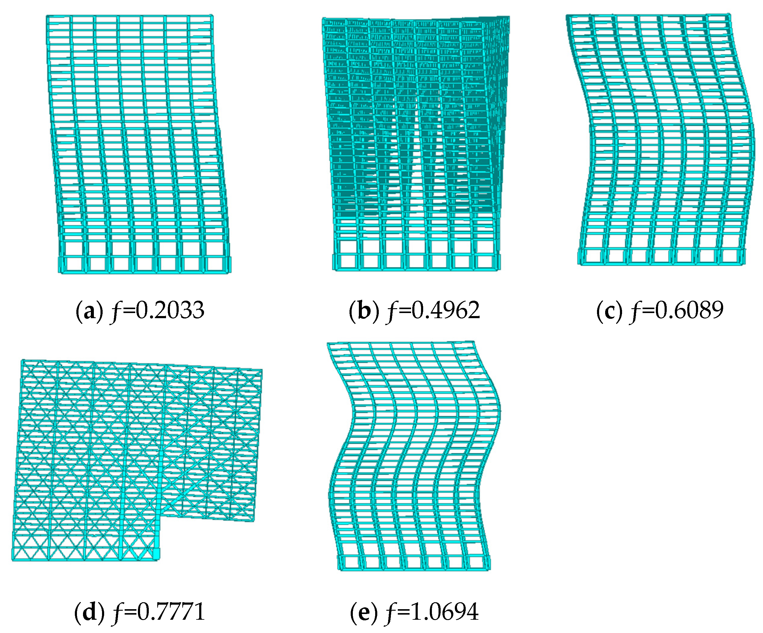
3.2.3. Analysis of Structural Frequency
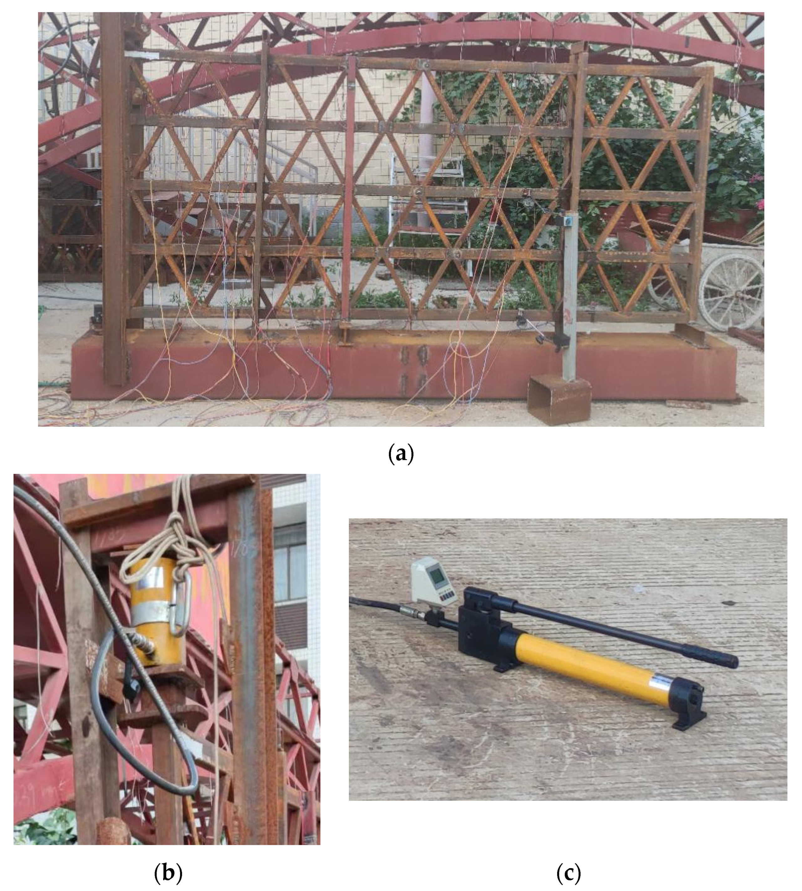
4. Stress and Stiffness Test of Plane Truss
4.1. Test Model Parameters and Load Conditions
- Test model I: A unit truss with 1.2 m cantilever segment. The size of test model I is 3.2 m × 0.35 m, and the height–cantilever ratio is 0.29. Load 2 tons on the cantilever segment end.
- Test model II: Two vertical overlap unit trusses with 1.2 m cantilever segment. The size of test model II is 3.2 m × 0.7 m, and the height–cantilever ratio is 0.58. Load 4 tons on the cantilever segment end.
- Test model III: Three vertical overlap unit trusses with 1.2 m cantilever segment. The size of the test model III is 3.2 m × 1.05 m, and the height–cantilever ratio is 0.87. Load 6 tons on the cantilever segment end.
- Test model IV: Four vertical overlap unit trusses with 1.2 m cantilever segment. The size of test model IV is 3.2 m × 1.4 m, and the height–cantilever ratio is 1.16. Load 8 tons on the cantilever segment end.
4.2. Arrangement of Measuring Points
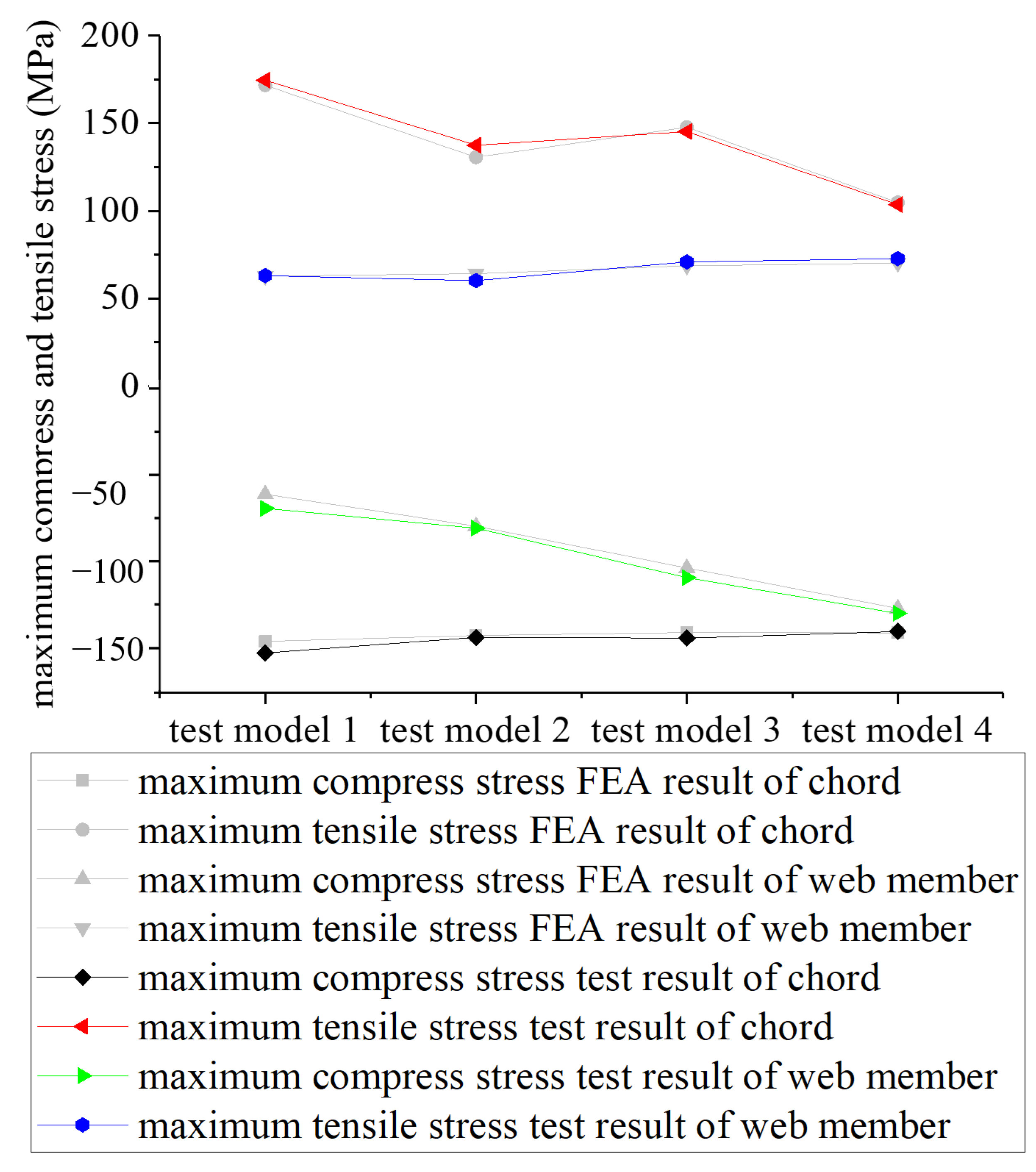
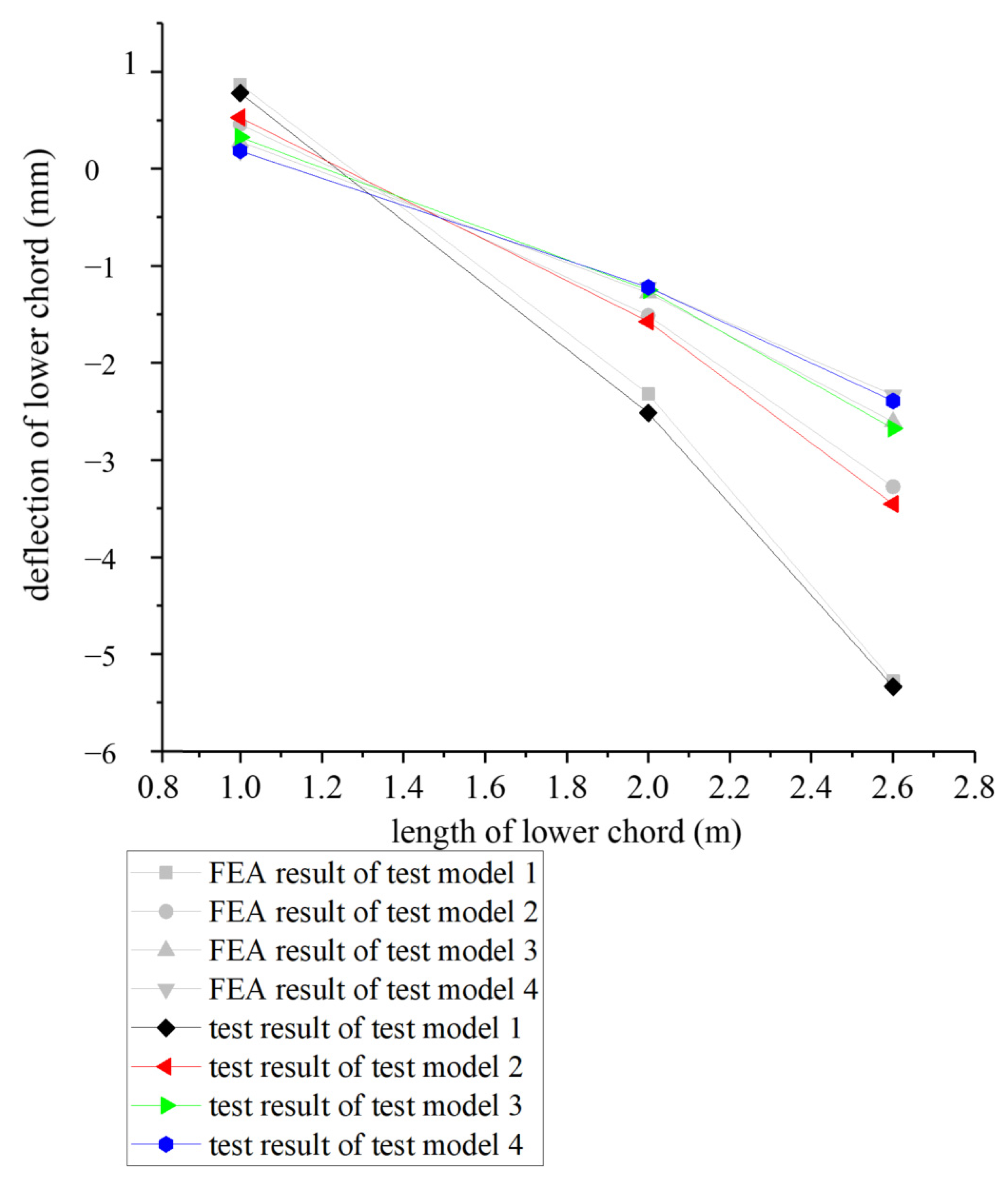
4.3. Test Results
4.4. Test Conclusion
5. Conclusions
- The piles and columns at the intersection of the shore segment and cantilever segment need to bear about half of the load. Therefore, it needs to be strengthened. Web members transmit the vertical forces into the column, so the pile below the column essentially needs to bear more vertical force than the pile below the web member.
- In the cantilever segment, the web members can transfer vertical force more efficiently than the beams. The vertical force transmitted by the former accounts for more than 90%. So, the super-long cantilever is based on the proposed wharf structure.
- The three-dimensional cantilevered wharf has good mechanical properties and economic performance. It transforms the planar wharf mode into a three-dimensional wharf mode, which improves the space utilization efficiency.
Author Contributions
Funding
Data Availability Statement
Conflicts of Interest
References
- Chen, K.; Chen, D.; Sun, X.; Yang, Z. Container Ocean-transportation System Design with the factors of demand fluctuation and choice inertia of shippers. Transp. Res. Part E Logist. Transp. Rev. 2016, 95, 267–281. [Google Scholar] [CrossRef]
- Kim, T.; Lee, W.D. Review on applications of machine learning in coastal and ocean engineering. J. Ocean Eng. Technol. 2022, 36, 194–210. [Google Scholar] [CrossRef]
- Yu, D.; Ye, J. Numerical modelling of the creep subsidence of an ocean lighthouse constructed on a reclaimed Coral Reef Island. KSCE J. Civ. Eng. 2021, 25, 1191–1203. [Google Scholar] [CrossRef]
- Chen, C.; Melville, B.W.; Nandasena, N.A.K.; Shamseldin, A.Y.; Wotherspoon, L. Experimental study of uplift loads due to tsunami bore impact on a wharf model. Coast. Eng. 2016, 117, 126–137. [Google Scholar] [CrossRef]
- Jia, C.; Yi, X.Y.; Guo, C.; Tan, H. Influence of wave direction on uplift force of sloping high piled wharf. J. Coast. Res. 2016, 2016, 1442–1446. [Google Scholar] [CrossRef]
- Lu, Y. The Optimization of automated container terminal scheduling based on proportional fair priority. Math. Probl. Eng. 2022, 2022, 7889048. [Google Scholar] [CrossRef]
- Nikolaieva, L.L.; Omelchenko, T.Y.; Haichenia, O.V. Hierarchical Management System for Container Vessels Automated Cargo Handling. J. ETA Marit. Sci. 2024, 12, 25–35. [Google Scholar] [CrossRef]
- Chang, Y.M.; Zhu, X.N.; Wang, L. Review on integrated scheduling of container terminals. J. Traffic Transp. Eng. 2019, 19, 136–146. (In Chinese) [Google Scholar]
- Niu, B.; Liu, Q.; Wang, Z.; Tan, L.; Li, L. Multi-objective bacterial colony optimization algorithm for integrated container terminal scheduling problem. Nat. Comput. 2021, 20, 89–104. [Google Scholar] [CrossRef]
- Zhou, Y.; Zheng, Y.; Liu, Y.; Pan, T.; Zhou, Y. A hybrid methodology for structural damage detection uniting FEM and 1D-CNNs: Demonstration on typical high-pile wharf. Mech. Syst. Signal Process. 2022, 168, 108738. [Google Scholar] [CrossRef]
- Madabhushi, G.S.; Boksmati, J.I.; Torres, S.G. Numerical and centrifuge modeling of gravity wharf structures subjected to seismic loading. J. Waterw. Port Coast. Ocean Eng. 2020, 146, 04020007. [Google Scholar] [CrossRef]
- Dai, J.; Wang, D.Y.; Zuo, X.F.; He, T. A new overhead vertical wharf in inland rivers of Three Gorges Reservoir. Yangtze River 2014, 45, 44–47. (In Chinses) [Google Scholar]
- Liu, Y.X.; Wu, L.D.; Li, Y.Y. A new type of wharf structure the structure of semi—Covered type of deep water sheet pile wharf. Port Eng. Technol. 2005, 2002, 16–19. (In Chinses) [Google Scholar]
- Boroschek, R.L.; Baesler, H.; Vega, C. Experimental evaluation of the dynamic properties of a wharf structure. Eng. Struct. 2011, 33, 344–356. [Google Scholar] [CrossRef]
- Xie, Y.F.; Liu, C.L.; Gao, S.Y.; Tang, J.P.; Chen, Y. Lateral load bearing capacity of offshore high-piled wharf with batter piles. Ocean Eng. 2017, 142, 377–387. [Google Scholar] [CrossRef]
- Mai, H.T.; Lieu, Q.X.; Kang, J.; Lee, J. A novel deep unsupervised learning-based framework for optimization of truss structures. Eng. Comput. 2023, 39, 2585–2608. [Google Scholar] [CrossRef]
- Yao, H.; Huang, Y.; Ma, W.; Liang, L.; Zhao, Y. Dynamic Analysis of a Large Deployable Space Truss Structure Considering Semi-Rigid Joints. Aerospace 2023, 10, 821. [Google Scholar] [CrossRef]
- Qin, X.; Liang, M.Z.; Xie, X.L.; Song, H.L. Mechanical performance analysis and stiffness test of a new type of suspension bridge. Front. Struct. Civ. Eng. 2021, 15, 1160–1180. [Google Scholar] [CrossRef]
- Hou, B.R.; Li, X.; Ma, X.; Du, C.; Zhang, D.; Zheng, M.; Ma, F. The cost of corrosion in China. Npj Mater. Degrad. 2017, 1, 4. [Google Scholar] [CrossRef]
- Qian, B.; Hou, B.R.; Zheng, M. The inhibition effect of tannic acid on mild steel corrosion in seawater wet/dry cyclic conditions. Corros. Sci. 2013, 72, 1–9. [Google Scholar] [CrossRef]
- GB50017–2017; Standard for Design of Steel Structures. China Architecture & Publishing & Media Co., Ltd.: Beijing, China, 2017.
- GB50009-2012; Load Code for the Design of Buildings Structures. China Architecture & Publishing & Media Co., Ltd.: Beijing, China, 2012.


| Component | Section Form | Material | Area (m2) | Ixx (m4) | Iyy (m4) | Izz (m4) | Amount of Steel Used (t) | Amount of Concrete Used (m3) |
|---|---|---|---|---|---|---|---|---|
| column | box section | Q420 | 0.0290 | 0.000152 | 0.000102 | 0.000102 | 24,683 | - |
| concrete filled steel box column | concrete filled steel box | Q420 and C40 | 2.99 | 7.959 | 4.591 | 4.591 | 2125 | 8308 |
| main beam | box section | Q420 | 0.0507 | 0.000527 | 0.000716 | 0.000222 | 61,288 | - |
| secondary beam | box section | Q420 | 0.0140 | 0.000285 | 0.000670 | 0.000101 | 1649 | - |
| foundation main beam | rectangular | C40 | 1.62 | 0.300 | 0.437 | 0.109 | - | 3278 |
| web member | box section | Q420 | 0.0116 | 0.0274 | 0.0183 | 0.0183 | 44,987 | - |
| pile foundation | circular | C60 | 3.14 | 1.571 | 0.785 | 0.785 | - | 22,579 |
| floor slab | - | C40 | - | - | - | - | - | 102,707 |
| Type | Elastic Modulus E (GPa) | Compressive Strength fc (MPa) | Tensile Strength ft (MPa) | Unit Weight γ (kN/m3) |
|---|---|---|---|---|
| C40 | 32.5 | 19.1 | 1.71 | 25.49 |
| C60 | 36 | 27.5 | 2.04 | 25.49 |
| Q235 | 206.03 | 215 | 215 | 76.98 |
| Q420 | 210.06 | 375 | 375 | 76.98 |
| Vertical Force | Load Combination I | Load Combination II | ||
|---|---|---|---|---|
| Vertical Force (kN) | Percentage (%) | Vertical Force (kN) | Percentage (%) | |
| the first row of offward piles | 4,356,697 | 51.78 | 3,676,220 | 51.68 |
| the second row of piles | 513,058 | 6.10 | 357,808 | 5.03 |
| the third row of piles | 1,612,478 | 19.17 | 1,211,586 | 17.03 |
| the rest of piles | 1,931,211 | 22.95 | 1,867,178 | 26.25 |
| Cantilever Segment Internal Force | Load Combination I | Load Combination II | ||||
|---|---|---|---|---|---|---|
| Shearing Force of Main Beam (kN) | Axial Force of Web Member (kN) | Vertical Component of Web Member (kN) | Shearing Force of Main Beam (kN) | Axial Force of Web Member (kN) | Vertical Component of Web Member (kN) | |
| maximum value | 1286 | 143,715 | 96,164 | 883 | 101,497 | 67,915 |
| summarized value | 112,038 | 3,783,293 | 2,531,517 | 76,261 | 2,623,155 | 1,755,233 |
| Vertical force percentage | 4.24% | / | 95.76% | 4.16% | / | 95.84% |
| Main Components | Load Combination I | Load Combination II | Load Combination III | |||
|---|---|---|---|---|---|---|
| Compressive Stress (MPa) | Tensile Stress (MPa) | Compressive Stress (MPa) | Tensile Stress (MPa) | Compressive Stress (MPa) | Tensile Stress (MPa) | |
| column | −302.7 | 180.9 | −231.3 | 127.8 | −216.8 | 108.1 |
| main beam | −239.1 | 270.9 | −167.2 | 180.6 | −144.1 | 149.0 |
| web member | −268.8 | 196.3 | −176.3 | 127.4 | −151.0 | 106.4 |
| Part of Structure | Maximum Deflection of Floor Slab (mm) | Maximum Vertical Deformation of Column (mm) | Relative Deflection (mm) |
|---|---|---|---|
| second floor of shore segment | 21.23 | 5.31 | 15.92 |
| top floor of shore segment | 53.62 | 40.01 | 13.61 |
| top floor of cantilever segment | 112.34 | 89.64 | 22.70 |
| Component | Section Type | Section Dimensions (mm) | Material | Model 1 (t) | Model 2 (t) | Model 3 (t) | Model 4 (t) |
|---|---|---|---|---|---|---|---|
| chord | box-shaped section | 60 × 30 × 3.5 | Q235 steel | 0.0292 | 0.0438 | 0.0584 | 0.0730 |
| web member | real-circular section | 30 × 30 × 3.5 | Q235 steel | 0.0188 | 0.0376 | 0.0564 | 0.0751 |
| vertical member | real-circular section | 50 × 50 × 4 | Q235 steel | 0.0057 | 0.0114 | 0.0172 | 0.0229 |
| Component | Stress (MPa) | ||
|---|---|---|---|
| Middle of Simply Supported Segment | Cantilever Segment | ||
| Cantilever Support Line | Right Section of the Middle | ||
| test model I | |||
| chord 1 | 72.1 | 174.6 | 55.4 |
| chord 2 | −70.2 | −152.2 | −70.8 |
| test model II | |||
| chord 3 | 60.3 | 137.5 | 65.0 |
| chord 4 | −1.0 | 56.7 | −22.2 |
| chord 5 | −68.8 | −143.4 | −64.5 |
| test model III | |||
| chord 6 | 64.1 | 145.2 | 50.2 |
| chord 7 | 20.7 | 58.4 | 22.5 |
| chord 8 | −21.5 | −62.4 | −32.6 |
| chord 9 | −55.3 | −143.7 | −55.0 |
| test model IV | |||
| chord 10 | 56.8 | 103.6 | 63.2 |
| chord 11 | 27.3 | 73.1 | 20.5 |
| chord 12 | 2.6 | 40.2 | −4.5 |
| chord 13 | −28.0 | −53.3 | −32.4 |
| chord 14 | −44.8 | −140.0 | −52.9 |
| Test Point | Stress | Test Point | Stress |
|---|---|---|---|
| test model I | |||
| 1 | 63.1 | 2 | −69.7 |
| test model II | |||
| 3 | −75.0 | 4 | 58.1 |
| 5 | 60.2 | 6 | −81.0 |
| test model III | |||
| 7 | 65.1 | 8 | −72.4 |
| 9 | −71.0 | 10 | 70.9 |
| 11 | 62.8 | 12 | −109.3 |
| test model IV | |||
| 13 | −82.2 | 14 | 48.7 |
| 15 | −89.1 | 16 | 72.8 |
| 17 | 67.3 | 18 | −90.1 |
| 19 | 58.7 | 20 | −129.6 |
| Component | Deflection (mm) | ||
|---|---|---|---|
| Simply Supported Segment | Cantilever Segment | ||
| Middle | End | ||
| test model I | |||
| chord 1 | 0.73 | −2.56 | −5.33 |
| chord 2 | 0.71 | −2.55 | −5.34 |
| test model II | |||
| chord 3 | 0.47 | −1.58 | −3.57 |
| chord 4 | 0.43 | −1.58 | −3.52 |
| chord 5 | 0.46 | −1.62 | −3.48 |
| test model III | |||
| chord 6 | 0.27 | −1.35 | −2.83 |
| chord 7 | 0.25 | −1.36 | −2.82 |
| chord 8 | 0.24 | −1.32 | −2.74 |
| chord 9 | 0.26 | −1.30 | −2.71 |
| test model IV | |||
| chord 10 | 0.06 | −1.24 | −2.60 |
| chord 11 | 0.07 | −1.30 | −2.62 |
| chord 12 | 0.11 | −1.31 | −2.47 |
| chord 13 | 0.08 | −1.27 | −2.41 |
| chord 14 | 0.12 | −1.27 | −2.43 |
Disclaimer/Publisher’s Note: The statements, opinions and data contained in all publications are solely those of the individual author(s) and contributor(s) and not of MDPI and/or the editor(s). MDPI and/or the editor(s) disclaim responsibility for any injury to people or property resulting from any ideas, methods, instructions or products referred to in the content. |
© 2024 by the authors. Licensee MDPI, Basel, Switzerland. This article is an open access article distributed under the terms and conditions of the Creative Commons Attribution (CC BY) license (https://creativecommons.org/licenses/by/4.0/).
Share and Cite
He, X.; Qin, X.; Huang, M.; Xie, X.; Du, C.; Fan, W. A New Type of Wharf and a Study of Its Mechanical Properties by FE (Finite Element) and Experimental Methods. Buildings 2024, 14, 2067. https://doi.org/10.3390/buildings14072067
He X, Qin X, Huang M, Xie X, Du C, Fan W. A New Type of Wharf and a Study of Its Mechanical Properties by FE (Finite Element) and Experimental Methods. Buildings. 2024; 14(7):2067. https://doi.org/10.3390/buildings14072067
Chicago/Turabian StyleHe, Xiang, Xia Qin, Mian Huang, Xiaoli Xie, Chenhao Du, and Wenyang Fan. 2024. "A New Type of Wharf and a Study of Its Mechanical Properties by FE (Finite Element) and Experimental Methods" Buildings 14, no. 7: 2067. https://doi.org/10.3390/buildings14072067
APA StyleHe, X., Qin, X., Huang, M., Xie, X., Du, C., & Fan, W. (2024). A New Type of Wharf and a Study of Its Mechanical Properties by FE (Finite Element) and Experimental Methods. Buildings, 14(7), 2067. https://doi.org/10.3390/buildings14072067