Abstract
This case study originates as a design experiment for a sustainable housing system built on-site. The context is Niamey, the capital of Niger. The study takes into account the environmental issues in the construction sector and aims to find a solution capable of meeting housing, environmental, and economic needs. In the field of earthen construction, the most important developments have been achieved in manufacturing methods. In particular, the use of an additive digital manufacturing system, such as large-scale 3D printing, allows the construction of complex shapes derived from structural and thermal studies, maintaining a high degree of automation in the construction process, reducing construction times and labor costs. This paper investigates the possibility of responding to housing and environmental needs with a settlement system made almost entirely of printed earth, maintaining the highest possible degree of automation. Starting from a study on the state of the art of 3D printing in architecture and printable earthen compounds, the design choices of similar cases are analyzed to understand the construction techniques, potentials, and limitations of the medium. Finally, a design proposal is developed based on the definition of a fully printable functional module, which, upon aggregation, determines the characteristics of the final settlement. This implies a radical change of approach compared to previous prototyping of 3D-printed earthen buildings, as the design of the single functional module is not an exercise that finds completion in itself, but is oriented to the scale of the settlement right from the definition of its basic geometric characteristics. In other words, the settlement is no longer the result of the serial aggregation of independent basic units, but arises spontaneously from the juxtaposition of functional modules designed to interact with each other and merge into a single residential complex. The settlement is, therefore, the large-scale replication of the alternation between full and empty spaces that characterizes the single functional module and, even more importantly, the replication can take multiple forms. In fact, the full and empty spaces of the functional module are planned to allow multiple combinations of aggregation. This introduces a certain degree of customization into the growth dynamics of the settlement, a factor that is entirely new compared to previous proposals by repeatable modules. No less important are the environmental implications, as designing for the scale of the settlement allows the low carbon footprint typical of earth-based construction to be extended from the single building to the entire settlement.
Keywords:
digitization; 3D printing; earthen materials; housing system; settlement; automation; sustainability 1. Introduction
In recent times, the progressive digitization of design and execution tools for architecture seems to open new opportunities that can significantly contribute to the increasingly urgent environmental, social, and economic issues [1,2].
Among the different construction technologies, large-scale 3D printing is a digital additive construction process that allows for the direct on-site creation of customized architectural solutions, even for residential purposes, optimizing the use of resources and raw materials [3]. In particular, the approach of direct 3D printing with earthen-based compounds [4,5] seems to offer a viable sustainable alternative to the use of concrete, which is widely adopted in conventional constructions but highly impactful from an environmental perspective. Suffice it to say that concrete is responsible for 8% of global carbon dioxide (CO2) emissions (concrete carbon footprint) [6], 90% of which are due to the production of clinker, which is the main ingredient that gives concrete strength. For this reason, the Paris Climate Agreement stipulated that the global concrete industry must reduce emissions by 25% per m3 of concrete by 2030, and 100% by 2050 to stay within the 1.5 °C warming carbon budget [7]. Therefore, reducing the demand for carbon-intensive clinkers with new techniques and new ingredients is an imperative that poses a great challenge to researchers in the construction industry. From this perspective, the present article offers an overview of the limitations and application potentials of large-scale direct 3D printing with earthen compounds, associated with the use of computational–parametric design tools [8], for the realization of sustainable housing systems.
The work presents multiple objectives, tools, and methods, and sees in the coordination capacity of the architectural project an opportunity to support the entire methodological framework. Oriented towards reducing the time and emissions due to production, transportation, and assembly, this design of the earthen housing system focuses both on the possibility of on-site production and on achieving a high level of automation in the construction process through the much sought-after wall–roof continuity. The design choice which allowed us to cope with the mechanical properties of the earthen material (a compression-resistant material) and avoid the use of temporary works, was to recover ancient construction techniques based on the funicular of loads. From the point of view of the construction technique, this involved the use of robotic arms capable of depositing material on non-horizontal planes.
The work began with the definition of a fully printable functional module that complies with the requirement of wall–roof continuity. This functional module can be considered an evolution of the robotic arm printing system developed by WASP (acronym for the World’s Advanced Saving Project), an Italian company pioneering the production of 3D printers for earthen structures. The evolution is twofold: (1) employ three robotic arms working simultaneously to extrude the functional module (the maximum number of collaborating robotic arms experienced by WASP is two) and (2) design the functional module as a basic unit of programmed expansion, capable of generating an entire settlement. Although it is commonly recognized that 3D printing with the simultaneous extrusion-arm technology developed by WASP is suitable for modular expansion, to the authors’ knowledge this is the first example of a complete modular urbanization project. A central part dedicated to services, in fact, integrates the set of modules—aggregated in such a way as to form a settlement—and meets all the needs of individual sustenance and community living. Roof and vertical closure, the two construction elements of the functional module, were then studied in order to ensure the stability of the module both during the realization phase and once construction is completed. The validity of the system was subsequently verified by designing a possible application.
2. Premises on Environmental Sustainability in Construction
Human activity over the centuries has significantly impacted current environmental conditions. According to the “2022 Global Climate Highlights”, 2022 was the second warmest year on record in Europe and the fifth warmest globally. It has been recorded that the average annual temperatures have risen by 0.3 degrees compared to the reference period (1991–2020), and by 1.2 degrees compared to the pre-industrial period (1850–1900) [9]. This makes 2022 the eighth consecutive year in which the average annual temperatures exceed the pre-industrial period temperatures by one degree. These temperatures have caused environmental upheavals and damaging phenomena across the globe. It is therefore crucial to halt the temperature increase before reaching an average annual increase of two degrees compared to the pre-industrial level, a temperature beyond which we will face irreversible effects on the environment.
It is commonly believed that the increase in average temperatures is due to the constant rise in the amount of CO2 released into the atmosphere. Although global CO2 levels are slightly decreasing, the entire construction sector contributes 38% to the amount of carbon dioxide emitted [9]. Current directives aim at the construction of NZEB (Near-Zero-Emission Building), buildings with very high energy performance, whose energy needs are very low and almost entirely covered by renewable energy sources. However, 10% of global emissions are due to the production, transportation, and subsequent disposal of construction materials. It follows that we must act not only on the energy impact that the building has during its life, but also on the construction materials, employing construction systems whose production releases less CO2 into the environment [2], are easily disposable, and minimize transportation between the factory and the construction site.
2.1. Building with Earth
Regarding earthen compounds, it should be emphasized that the novelty does not lie in the material itself, but in the fabrication method used to construct the buildings.
The use of earth as a building material offers numerous advantages: it is recyclable, easily available, and inexhaustible, it is not harmful, has decent compressive strength, and excellent hygrothermal properties. The porous nature of the material, indeed, results in the ability to absorb and release moisture, ensuring stable temperatures throughout the year [10]. If properly designed, an earthen wall acts as a passive thermal regulator, further reducing the use of energy for active conditioning systems. Earthen constructions also have a positive effect on increasing the resilience of cities, helping to reduce heat islands [11,12].
Why do we not build with earth, then? Despite the numerous advantages, the choice to construct a new building with earth is extremely unusual because, depending on the cultural context, such a solution is still considered unconventional or primitive. As a consequence, unlike other materials such as reinforced concrete, earth has not reached an adequate level of experimentation that allows it to have an international standard. The lack of experimentation results in a lack of reliable data regarding the variations in mechanical and hygrometric characteristics based on different soil types, uncertainty about the various possibilities of reinforcing structural elements, and a lack of effective quality controls on constructions. Another source of uncertainty is durability, since there are still few and relatively recent prototypes of housing modules made entirely with 3D printing of earthen materials. It is worth noting that Gaia—the first earthen prototype 3D—printed in 2018 by WASP (Massa Lombarda, Italy), adopting a modular collaborative 3D printing system (Crane WASP) that reinterprets classic construction cranes from a digital manufacturing perspective—has shown good resistance to the continental atmospheric agents typical of the Italian climate, and does not yet show signs of damage. However, complete studies on the durability of 3D-printed earth over time in different climates (of fundamental interest for large-scale industrial adoption [13]) are still lacking. Finally, the construction times for earthen buildings are higher compared to other industrialized systems. In fact, the printing speed of a modern robotic arm is about 6 dcm3/min [14].
As regards the main technological problems that 3D printing of earthen materials partly shares with 3D printing of concrete [15,16], typically extrudability, buildability, and workability with time [17], they can rather be considered solved at the current state of research [18,19,20].
2.2. 3D Printing with Earth: The Challenge of Roofing
Currently, experiments on buildings made with 3D printing in earthen compounds are still limited compared to those involving the use of 3D-printed concrete. These case studies can be analyzed through different parameters; our specific focus is on the use of earth for structural purposes. As with traditional earthen constructions, in this case too, it is possible to distinguish two main construction principles: global 3D printing and 3D printing for hybrid construction systems. While a global approach involves the continuous printing of the entire building through the wall–roof continuity, the hybrid type involves the printing of vertical elements, which may or may not be load-bearing, combined with the use of roofs made with traditional construction methods and materials [21]. The challenge of gravity, even more crucial in the case of additive construction processes, has suggested the experimentation of hybrid construction approaches in which the roof, generally made of wood, is assembled after the printing of the perimeter walls and lays on them (Figure 1a). Differently, in the Gaia prototype (Figure 1b), the roof rests directly on an alternative vertical structure [22]. The only global approach realized so far is Tecla (Figure 1c), a unique experiment of its kind, composed of two modules (night area and day area), entirely made of load-bearing printed earth. On the roof, there is a skylight capable of providing illumination to the interior spaces. During the printing phase, some of the interior furnishings are also integrated, in order to speed up the time in which the house becomes available [23].
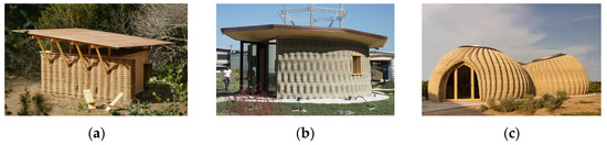
Figure 1.
Different support systems for the roofs of 3 D-printed houses with earthen materials: (a) The roof resting on the perimeter walls of Tova [24]; (b) The roof resting on internal wooden poles of Gaia [25]; (c) The roof of the global approach of Tecla [26].
3. Materials and Methods
3.1. Definition of the Project Concept
The functional module is designed to be realized through direct printing with a global approach; the elements are printed on-site and do not need further processing to meet the required performance. In this way, the automation of the construction process is maximized, reducing construction times and pollution due to the assembly and transportation of materials. The construction elements designed are self-supporting and do not require the installation of additional supports.
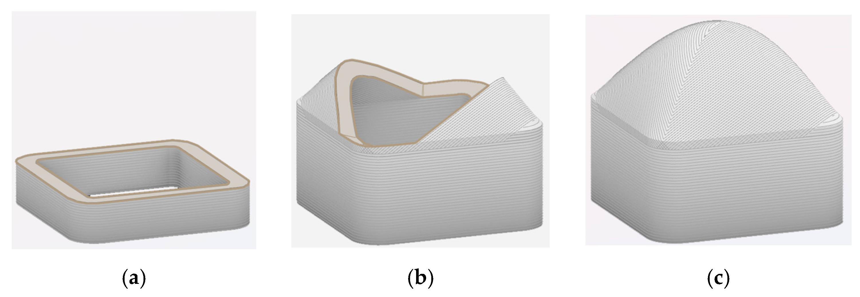
The designed module involves the definition of square-plan spaces (Figure 2a), covered by a vaulted element (Figure 2b). The printing strategy differs for the two construction elements. The wall layers are deposited along horizontal planes (Figure 3a), while the roof is printed along a diagonal by tilting the printing plane by 45° (Figure 3b,c). In this way, the layers forming the vault are always deposited on the underlying layer; during the printing phase, they have form resistance due to the creation of curved elements subject only to compression.
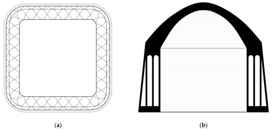
Figure 2.
General details of the functional module (for dimensions, see Section 3.2.2): (a) Plan of the module; (b) Section of the module.
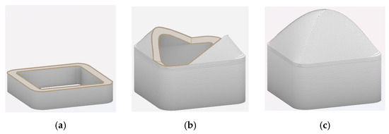
Figure 3.
Printing strategies for the walls and roof of the functional module: (a) Printing the walls on horizontal layers; (b) Printing the roofs on 45° inclined layers along the module’s diagonal; (c) Completed module.
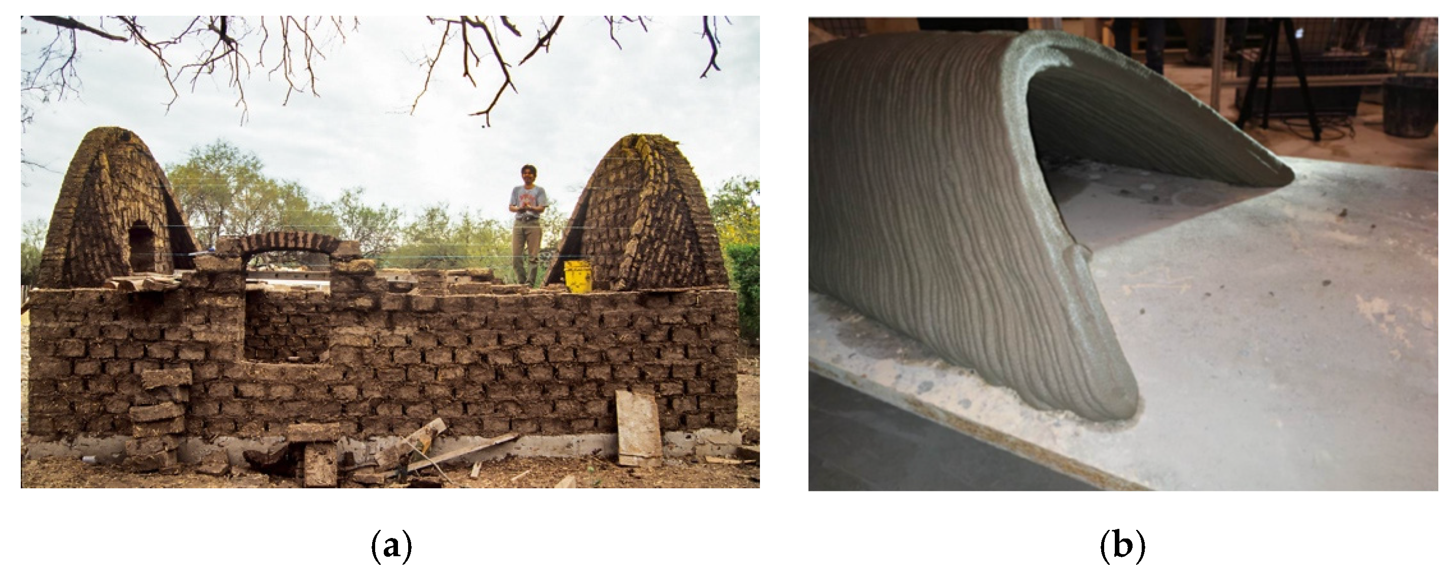
The printing process adopted derives from traditional Nubian vaults (Figure 4a), which are self-supporting vaults, meaning they can be constructed without any external support during the building phase. This characteristic is due to the inclination at which the rows of bricks are placed. Cutting the vault according to inclined planes and arranging the bricks along these planes ensures that the laid elements always rest on those previously placed [24]. The same principle is adopted and adapted through 3D printing. Prototypes of vaults have already been created using this process (Figure 4b), demonstrating how the inclination of the printing plane allows for an increase in the maximum printing inclination up to 60°.
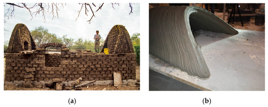
Figure 4.
The Nubian vault: (a) Traditional Nubian vault construction technique using raw earth bricks [27]; (b) Prototype of a vault 3D-printed with 40° inclined layers without supports [28].
Contrary to traditional horizontal slicing, in this case, the extruder, when printing a layer, moves simultaneously on the three axes x, y, and z, having to remain always perpendicular to the printing plane. This printing strategy therefore involves the use of robotic arms, which possess an extruder with 6 degrees of freedom and allow greater construction flexibility due to their ease of movement compared to framed systems. The use of robotic arms instead of large-format 3D printers in large-scale additive manufacturing also has a second motivation: unlike the latter, the robotic arms guarantee high precision in the positioning of the end effector [29].
3.2. Structural Design
The study of the structural design of the module was divided into two parts: the first concerning the analysis of the loads produced by the roof, and the second concerning the design of the wall based on the acting loads. First of all, the study on the mechanical characteristics and composition of the hypothesized compound (Table 1 and Table 2) is reported, based on the reference study [30] by Mohamed Gomaa.

Table 1.
Mix design of the printed compound [30].
Table 2.
Properties of the compound.
3.2.1. The Mechanical Properties of the Printed Material
The mix design of the printed compound is similar to a traditional cob mixture, with an increased percentage of water to ensure printability (Table 1). Natural fibers must be in the range of length of 30–50 mm in order to ensure the correct extrusion of the material by the printer; they have a beneficial effect in enhancing the compressive strength of the mixture [32] and in reducing the shrinkage of the printed elements [33]. However, it is worth noting that, regardless of the type chosen, there is always an upper limit in the percentage of natural fiber to be used, beyond which the compressive strength no longer increases but, on the contrary, begins to deteriorate [34,35].
There are no restrictions on the type of natural fiber to use, although some may be more useful than others. A recent study [18], for example, has shown that the high silica content and low alumina content of rice husk (RH), especially in the form of rice husk ash (RHA) or shredded RH, is of fundamental importance for increasing the compressive strength of earthen buildings. In this document, however, the authors wanted to privilege the local availability of all raw materials rather than the possibility of making the most of the mechanical resistance capabilities of earthen compounds. For this reason, the choice of the natural fiber to be used fell on wheat fiber, as wheat is a typical crop in the territory of insertion (Niger) of the developed project. Wheat fibers, on the other hand, are also used in the construction of cob [36,37], with respect to which 3D printing with earthen materials can be considered the digital evolution [18]. As with cob buildings [37], wheat fibers for 3D printing of earthen materials do not require any pre-treatment.
All the values reported in Table 2, except for the characteristic tensile strength, derive from axial compression tests on printed specimens [30]. For the characteristic tensile strength, average strength values of raw earth walls were used [31], due to the lack of data in this regard. This assumption was possible because the research shows that the mechanical characteristics of the printed specimen are in line with those of a traditional earthen specimen [38], and therefore the printing process does not affect the strengths (Table 2). We can summarize by saying that the material has a brittle behavior, works in compression, and does not have significant tensile strengths. It has lower strengths compared to traditional construction materials, which results in greater thicknesses of the structural elements.
3.2.2. Roof
Three modules of different sizes have been defined: 4, 9, and 12 sqm, and the roof has been designed for each of them. The shape of the vault is generated through Grasshopper; in particular, the kangaroo plugin has been used, which allows for the writing of an algorithm that simulates an elastic membrane subject to its own weight. It starts from a planar mesh having the same dimensions as the module, and, besides the geometry, the algorithm requires the information about the elasticity factor of the edges and the load to be applied on the nodes. The conditions used in the simulation were studied to obtain a roof profile with a contained height, and the results were qualitative and were used as a starting point for the following roof analysis. In this way, the roof is subjected to compression only.
The preliminary design of the roof was carried out through 3 checks: verification of the pressure curve passing within the middle third of the section, verification of the stresses at the keystone section, and verification of the stresses at the impost section.
12 sqm Block
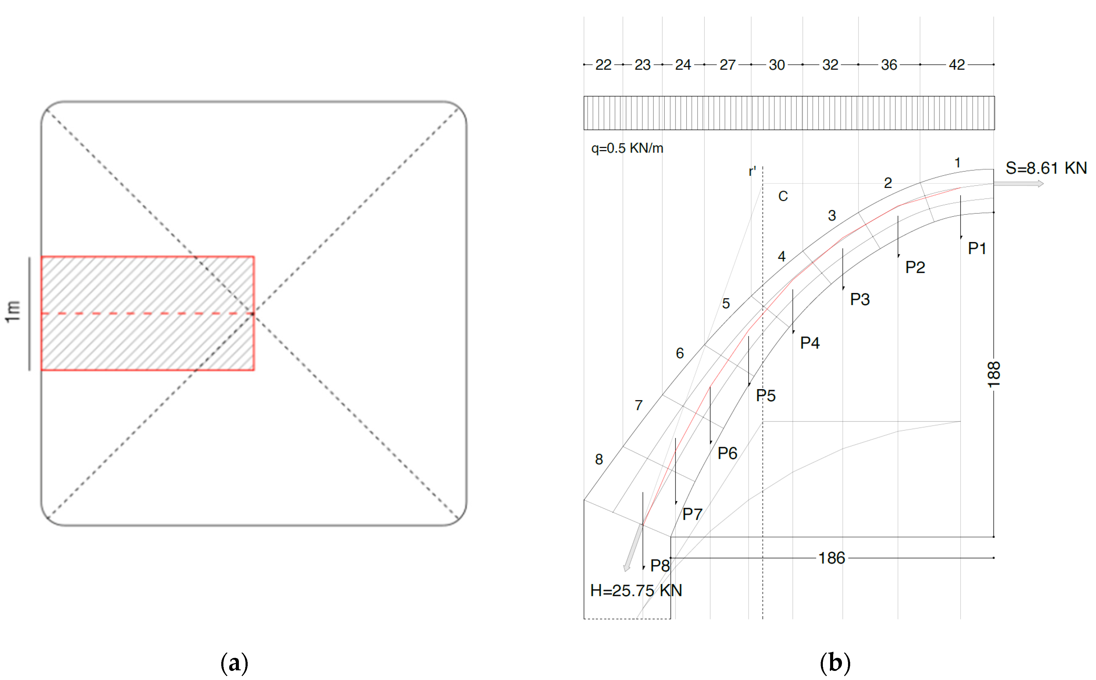
The verification of the pressure curve was carried out using a graphical method, considering the midline of the vault in its vertical plane (Figure 5a). This midline was divided into 8 fictitious arches of 1 m in length, for which the weights of the respective vault segments were calculated (Table 3). The weight vectors were applied to the centroids of the vault segments, which belong to the previously defined arches. Then, the force line was drawn (the line where the sum of the forces are applied) and the funicular polygon was constructed. To comply with the graphic rules for finding the resultant vector between incident vectors of the plane, the line of force—which is a vertical line—passes through the intersection point between the first and last sides of the polygon (Figure 5b). At this point, the line orthogonal to the key section applied into the upper third intersects the line r’ at a point C, giving us the line of action of the horizontal force. The line connecting the pole C and the lower-third middle part of the section at the impost gives us the line of action of the load at the impost. The line of forces has been decomposed according to the horizontal direction and the direction of the line of action at the impost. In this way, it was possible to derive the value of the horizontal force (S) at the keystone and the value of the total load (H) at the impost. Using point C as the projection pole, the pressure polygon was traced and its containment within the middle third of the arch was verified.
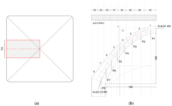
Figure 5.
Loads analysis: (a) Study band for the pressure curve; (b) Verification of the pressure curve passing through the middle third of the section.
Table 3.
Load exerted by each segment due to its own weight: load analysis carried out at the ULS.
Subsequently, an analysis on the stress state of the roof was carried out, and in particular, the two sections at the keystone and at the impost were verified. For the first, a bending compression check was carried out; since the pressure curve coincides with the upper middle third and is orthogonal to the plane of the studied section, the pressure will be of bending compression with a triangular diagram. As for the section at the impost, a bending compression and shear check was carried out, as the load is not orthogonal to the plane of the impost. For both verifications, it was verified that the applied stress was less than the design stress. The method used was the same as that for the verification of masonry vaults, as these exhibit similarities in behavior. It is indeed possible to assimilate the layers of the printed vault to the rows of bricks in the masonry vault.
Proceed to verify the bending stress in the key.
Design compression stress:
Applied stress:
with
- γ = Safety factor;
- b = Length of the block;
- s = Height of the block.
The verification is passed as Fe < Fd
Proceed to verify the bending and shear stresses at the impost. For bending:
Orthogonal force component at the impost:
Applied stress:
The verification is passed as Fe < Fd.
For shear verification:
Average normal stress on the section:
Maximum shear with normal force:
Design shear stress:
Parallel force component at the impost:
Applied shear:
The verification is passed as Fve < Fvd.
The same procedure was used for the verification of the 9 sqm and 4 sqm blocks, but only the final results are reported in Table 4 and Table 5.
Table 4.
The 9 sqm-block verifications.
Table 5.
The 4 sqm-block verifications.
3.2.3. Wall
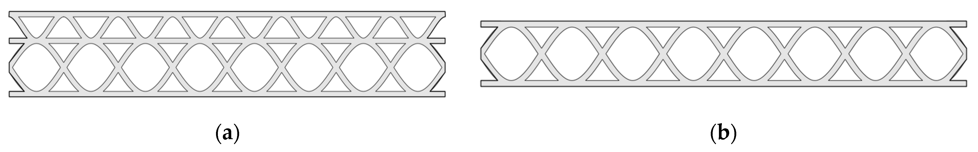
Two different types of walls were defined, perimeter wall (Figure 6a) and internal wall (Figure 6b). The first divides a covered space from an open space, supporting the weight of a single roof, the second divides two covered spaces and supports the weight of two roofs.

Figure 6.
Internal geometry of the walls: (a) Perimeter wall; (b) Internal wall.
The first case considered is where the wall supports the load of the two larger coverings—i.e., the internal wall between two 12 sqm modules—assuming that the load of the covering is uniformly distributed its length. This structural design is based on the procedure of Paper [30], one of the rare papers that provides design guidance for 3D-printed structures with earthen materials.
Following the limit state method, it is possible to define the design resistance as
with
- Pd = Design resistance;
- P = Maximum compression load;
- = Safety factor taken as 2.
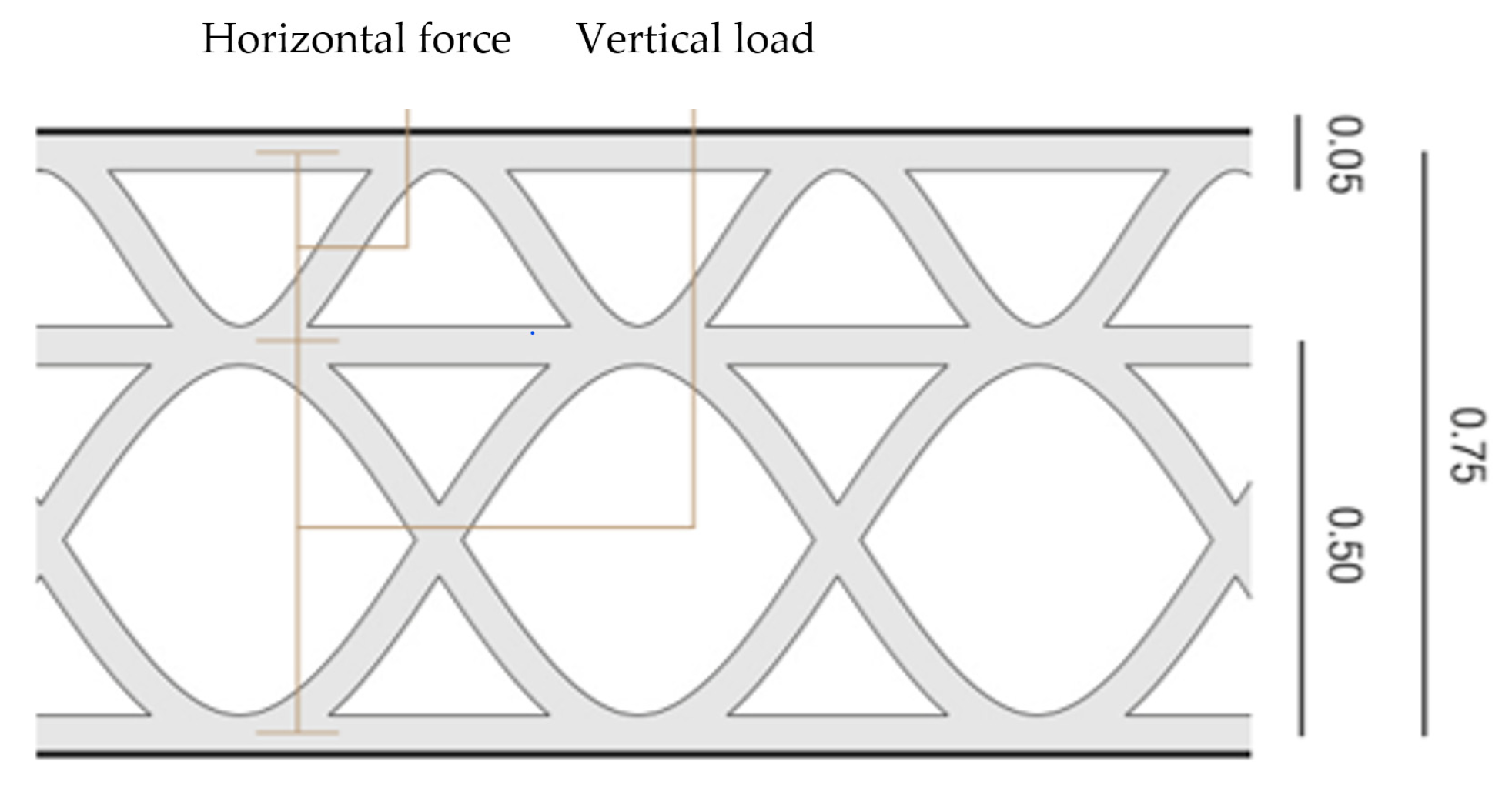
To define the compressive strength of the wall, it is first necessary to design the type of infill resistant to vertical loads. The geometry of the wall section (Figure 7a) was studied by formulating an algorithm in Grasshopper.
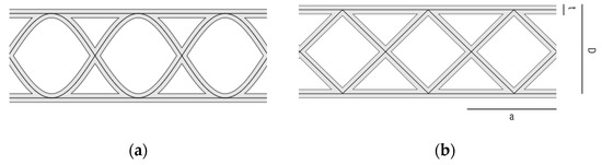
Figure 7.
Wall design: (a) Actual wall section; (b) Analyzed geometric simplification.
Highlighting how the infill step (a) is equal to the thickness (D) of the wall, in this way the entire section can be described with only two parameters (D) and (t) nozzle thickness.
For the evaluation of the mechanical compressive strength of the wall, the simplified resistant section (Figure 7b) was studied. We need the geometric characteristics of the section: Area (A) and Moment of Inertia (I). These quantities are studied on the simplified section (Figure 7b), dependent on the two parameters (D) and (t). For the evaluation of these characteristics, a wall section with a length (L) of 1000 mm and a height (H) of 2200 mm was studied.
Wall path length:
Moment of inertia of internal infill:
Moment of inertia of external shell:
Total moment of inertia:
The vertical loads were evaluated in the study of the roof; in this case, the stresses of the 12 sqm-block roof were used.
Considered loads:
- Roof weight Pr = 25.70 KN;
- Wall weight Pw = 1.3 18 10−9 (A 2000 + D ;
- Total weight Ptot = Pw + 2 Pr.
The maximum compressive strength of the wall is the lesser of the characteristic compressive strength of the material and the maximum stress due to local instability.
Maximum compressive strength of the wall [30]:
The first has already been determined by axial compression tests, and it is 0.62 MPa (Table 2), while the second was evaluated by studying the local instability of the individual elements that make the wall:
Effective buckling length:
Number of bucklings over the length:
Instability coefficient [39]:
Maximum stress for local instability of a simply supported plate [39]:
Finally, we can define the maximum stress value within the section, studied as a column subject to eccentric load with the possibility of global instability.
Maximum compressive stress [30]:
with
- Distance between the mid-axis of the wall and the outermost tensioned fiber c = [30];
- Maximum load for global instability [30];
- Total eccentricity of vertical loads e = [30];
- Eccentricity of the wall’s own weight em = 0.05D [30].
The maximum load is evaluated by solving Equation (20) for P. The geometry of the wall section is defined by the variables D wall thickness and t nozzle size. It is possible to optimize these dimensions to have the least amount of printed material and exactly the capacity needed to withstand the applied stresses. We define u, utilization coefficient [30]:
u is the ratio between the load applied on the wall (Ptot) and the design resistance of the wall (Pd). The ratio depends only on t and D, so it is possible to calculate the values of the pair (t,D) for which u = 1 and Pd = Ptot.
The study for the perimeter wall was carried out similarly, considering a perimeter wall of the 12 sqm-block, a halved vertical load, and taking into account the eccentricity of the vertical load of the overlying vault [30].
with
- Eccentricity of the wall weight em = 0.05D [30];
- Eccentricity of the roof weight ec = 0.16D [30].
When calculating the value of the maximum vertical load, the internal stress of the wall section due to the moment generated by the horizontal force of the roof was also evaluated.
with
- M = S
4. Results
4.1. Structural Design Results
The pairs (t,D) were found by writing a program in Python, finding all the values of u from the possible combinations of (t,D) and plotting the graph of the points of interest where u = 1.
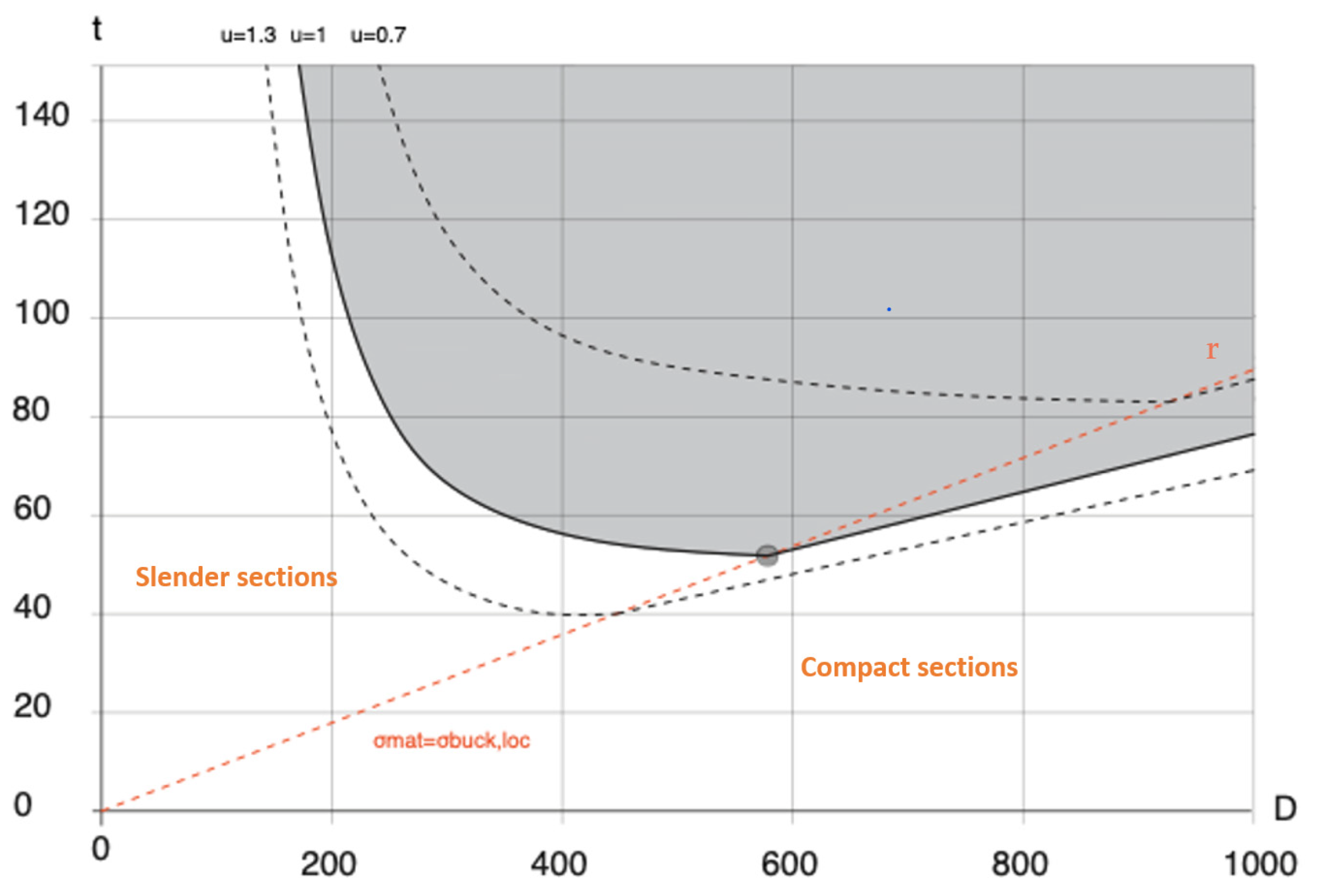
The obtained graph (Figure 8) represents the domain of sections with adequate capacity for the internal wall. The curve u = 1 follows two different trajectories, depending on whether it is in the region of compact or slender sections. In the region of compact sections, the maximum stress is the maximum compressive strength of the material (Table 2), while in the region of slender sections, the maximum strength is the maximum stress for local instability (19). We can observe how the domain has a minimum point, where the pairs (t,D) result in equal values of maximum stress for local instabilities and compressive strength of the material. The minimum coincides with the optimal point, where we have adequate strength to withstand the loads with the least amount of material used.
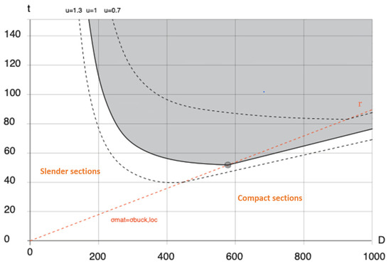
Figure 8.
Graph of the resistance domain of the internal wall section.
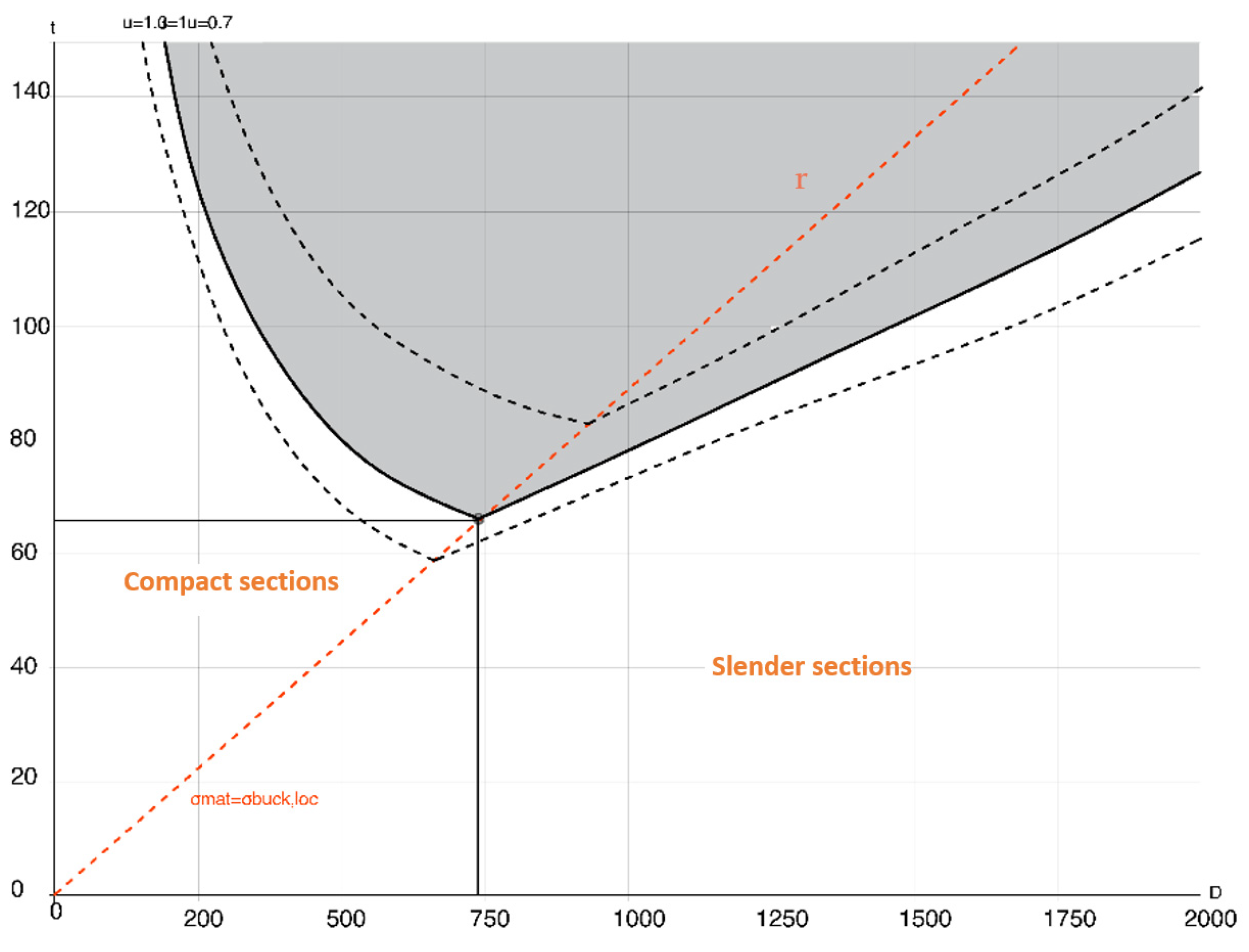
The graph just obtained was then compared with the one resulting from the preliminary design of the perimeter wall derived in a similar manner (Figure 9). In the latter, we notice that, although the value of the vertical load is halved compared to the intermediate case, the presence of the horizontal force of the roof leads to having optimal values of t and D greater than those of the internal wall.
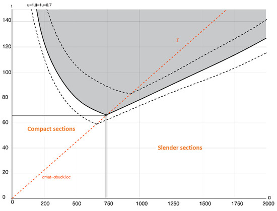
Figure 9.
Graph of the resistance domain of the perimeter-wall section.
The line r is given by all pairs (t,D) for which σinst,loc = 0.62 MPa [30], found using the instability formula for simply supported plates (19). The values obtained were compared with the values obtained from the simulations carried out in ABAQUS.
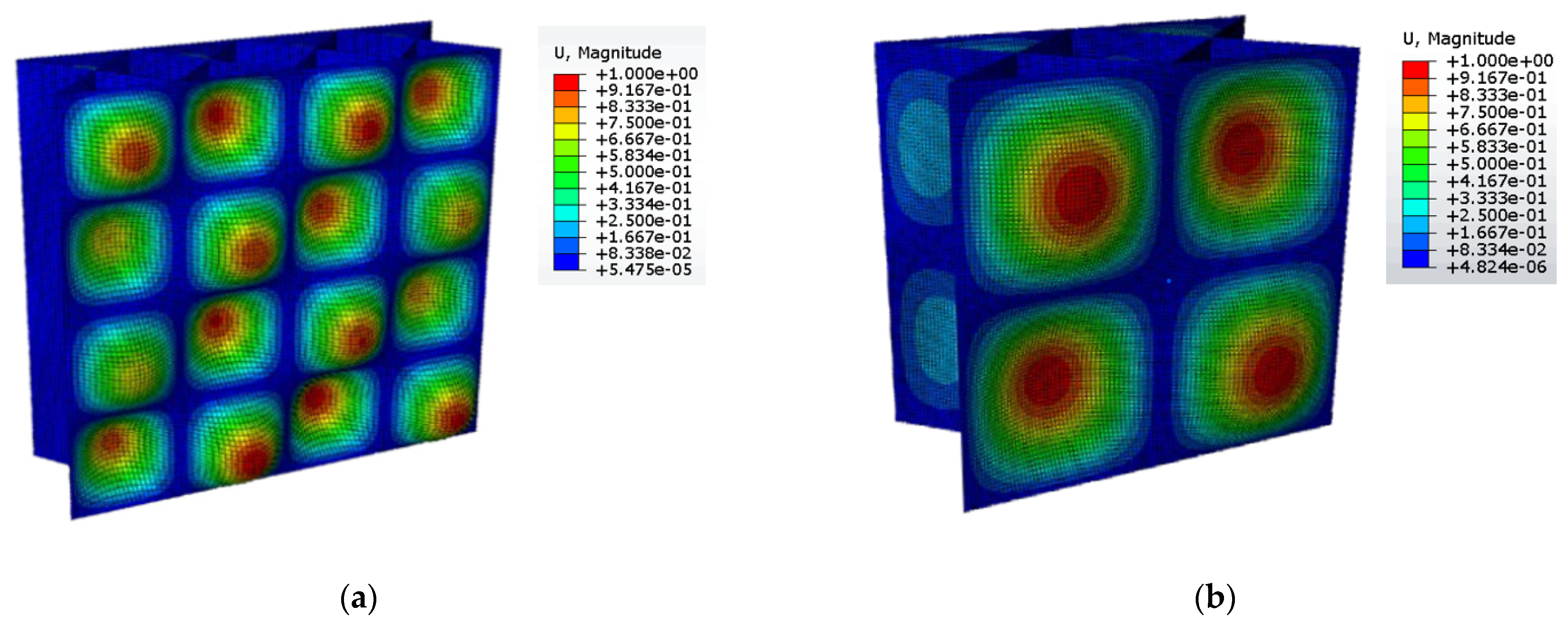
Two linear buckling analyses were carried out (Figure 10) to evaluate the instability values obtained on wall sections. Starting from the definition of the geometry, the length and height of the wall considered is 2000 mm, as studied in the reference paper [30], and the two walls have different infills depending on their thickness (D). All the elements in the wall sections were modelled as shells. The parameters (t) and (D) used for the modeling were taken from the line r drawn on the graph (Figure 8): in the first case D = 575 mm and t = 53 mm, in the second case D = 1000 mm and t = 90 mm. Then the material properties were defined using the values E = 22.9 MPa and ν = 0.22, as previously informed [30]. The model analyzed for both simulations is a wall section subjected to a uniform compressive force to its top and bottom boundaries, and the boundary conditions used are pins that also allow vertical movements. In both cases, the maximum stress values for instability, obtained through simulations, coincide with the maximum compressive stress of the material, validating the values obtained through Equation (19).

Figure 10.
Simulation results in ABAQUS (images showing the adimensional normalized nodal displacements, U): (a) D = 575 mm, t = 53 mm; (b) D = 1000 mm, t = 90 mm.
The wall project was concluded by verifying that the resultant force between the roof load and the wall weight was contained within the middle-third of the wall thickness at the base for both perimeter and internal walls (Figure 11), providing for a tapered outer layer capable of absorbing the horizontal thrusts of the roof, in the case of a perimeter wall (Figure 12).
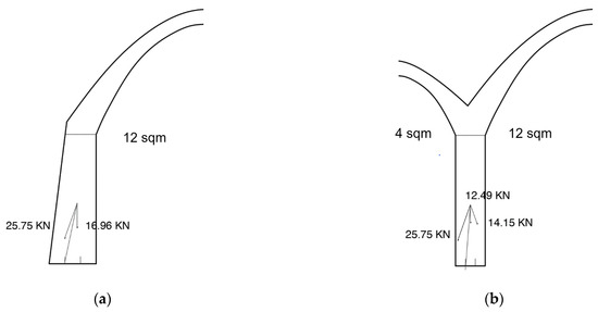
Figure 11.
Verification of the force passage within the middle-third of the wall base: (a) Perimeter wall; (b) Internal wall.
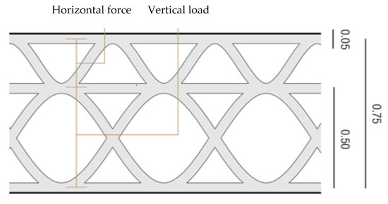
Figure 12.
Final infill definition for perimeter wall.
4.2. The Architectural Project
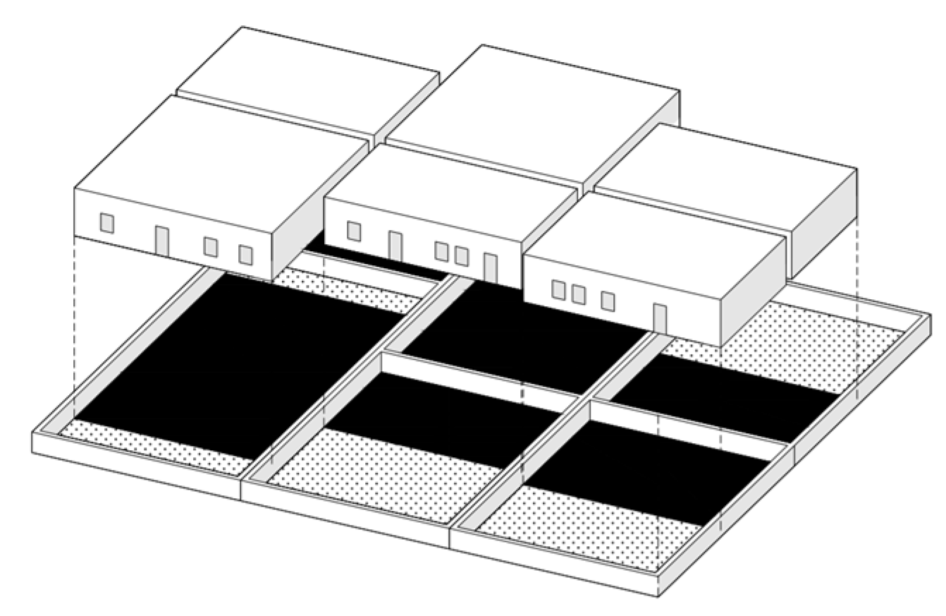
The project is located in the eastern outskirts of Niamey, in Niger, a North African state that is among the largest in terms of population growth [40]. The urban context is very dense and characterized by the presence of informal housing, the compounds (Figure 13)—a large-scale residential typology—where we find self-built blocks with few openings to the outside, built very close together and enclosed by a perimeter wall. The demand for modernization of the construction techniques used so far locally is leading to a loss of local identities, as imported materials are adopted, resulting in solutions that are not suitable for the context in which they are used.

Figure 13.
Compound layout.
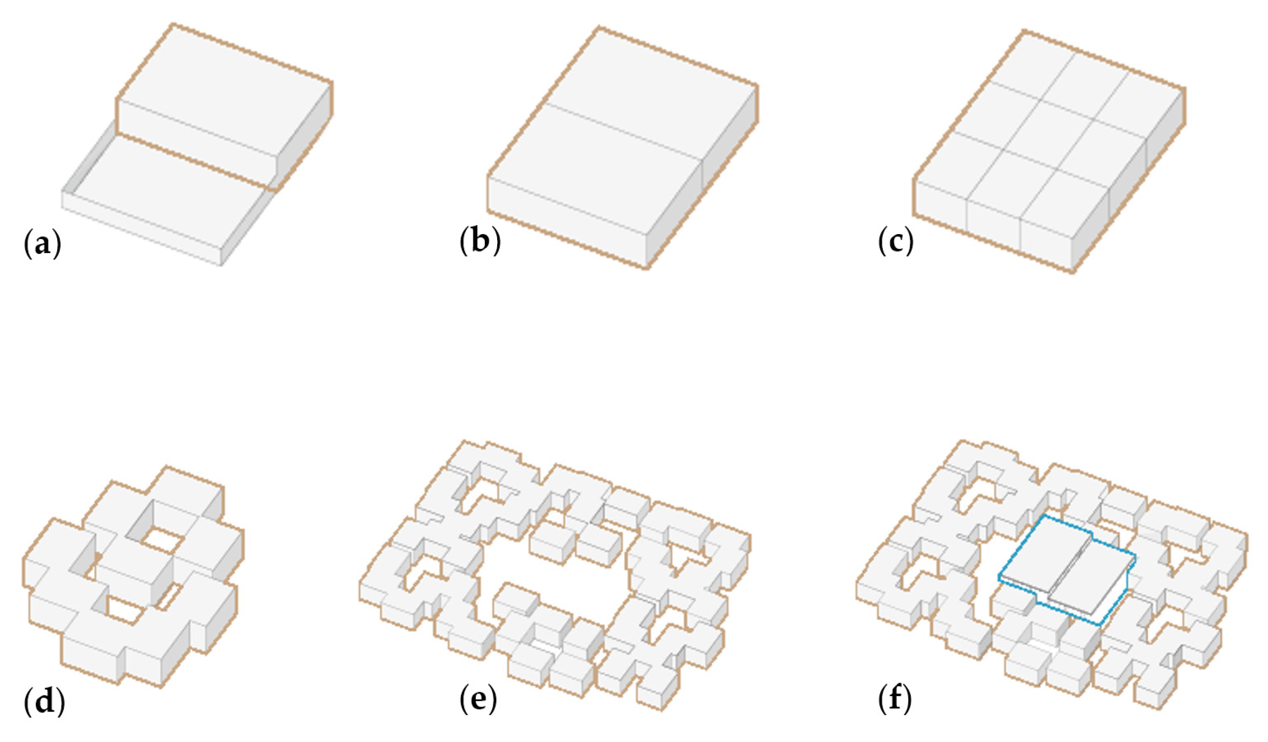
The intervention idea is summarized in six points and is based on the study of the traditional local way of living, characterized by a strong presence of community spaces:
- Starting from the average size of a current dwelling (Figure 14a);
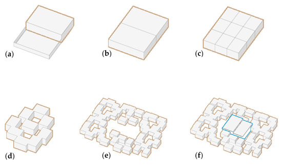 Figure 14. Settlement concept: (a) Current dwellings; (b) Increased density; (c) Module division; (d) Patio openings; (e) Aggregation; (f) Insertion of common spaces.
 - Increasing the density by creating two units where previously there was one unit in the same area (Figure 14b);
- The individual dwellings are divided into functional modules (Figure 14c);
- The modules are then arranged to create the new house (Figure 14d);
- The housing units are aggregated to create a settlment (Figure 14e);
- The system is completed with the insertion of central community spaces (Figure 14f).
The project consists of ten dwellings that enclose a central common space (Figure 15). The plan takes up the idea of a fenced compound. The design is based on the definition and arrangement of individual modules that represent the rooms fulfilling the functions of living. The jagged arrangement of the modules allows for the creation of residences where we find the alternation of covered spaces and shaded patios, as in extremely hot climates it is essential to be able to carry out part of the daily activities outdoors.
Regarding the relationship with the context, the dwellings have small heights, remaining on a single floor, not overshadowing the surroundings. The only block of greater height is the central collective building, arranged on two levels. Specifically, this central block is not made of load-bearing earth; instead, the walls printed with earth are positioned in a regular grid of wooden pillars that support the floors (Figure 16). Although this block has two floors, it has a much lighter character compared to the surrounding buildings.
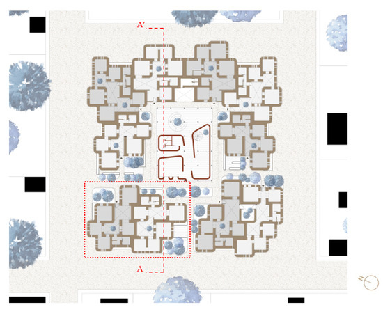
Figure 15.
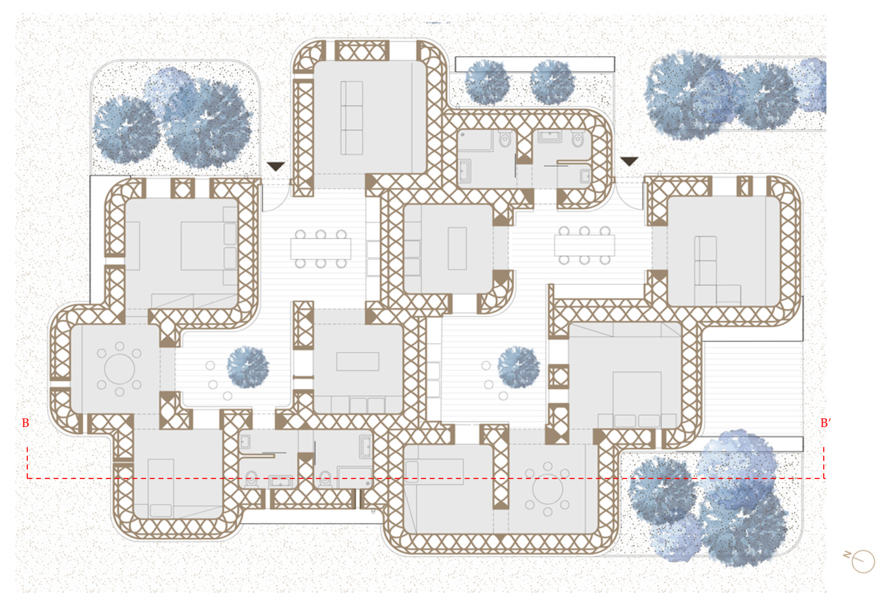
Ground-floor plan (the detail of the red area is shown in Figure 17).
Figure 15.
Ground-floor plan (the detail of the red area is shown in Figure 17).

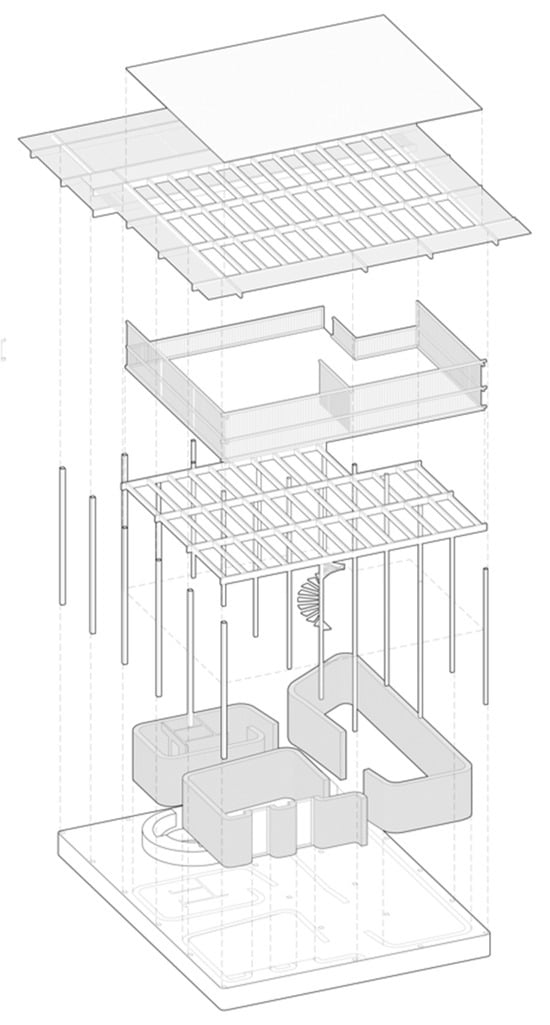
Figure 16.
Exploded view of the central block of common spaces.
Figure 16.
Exploded view of the central block of common spaces.

All housing units follow the same design logic (Figure 17): there is a division between the blocks of the living area and the blocks of the sleeping area, the latter being separated from the former by a study area that functions as a filter. The rooms are arranged around internal courtyards where there are vegetation, shared spaces, kitchens, and areas for outdoor dining. Each unit has its own covered kitchen. The outdoor kitchens are built adjacent to the service blocks to minimize the layout of the systems. It is possible to enter the homes through the internal paths of the aggregation and not from the street front.
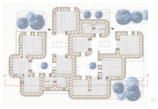
Figure 17.
Detail of the housing block, highlighted in Figure 15.
Figure 17.
Detail of the housing block, highlighted in Figure 15.
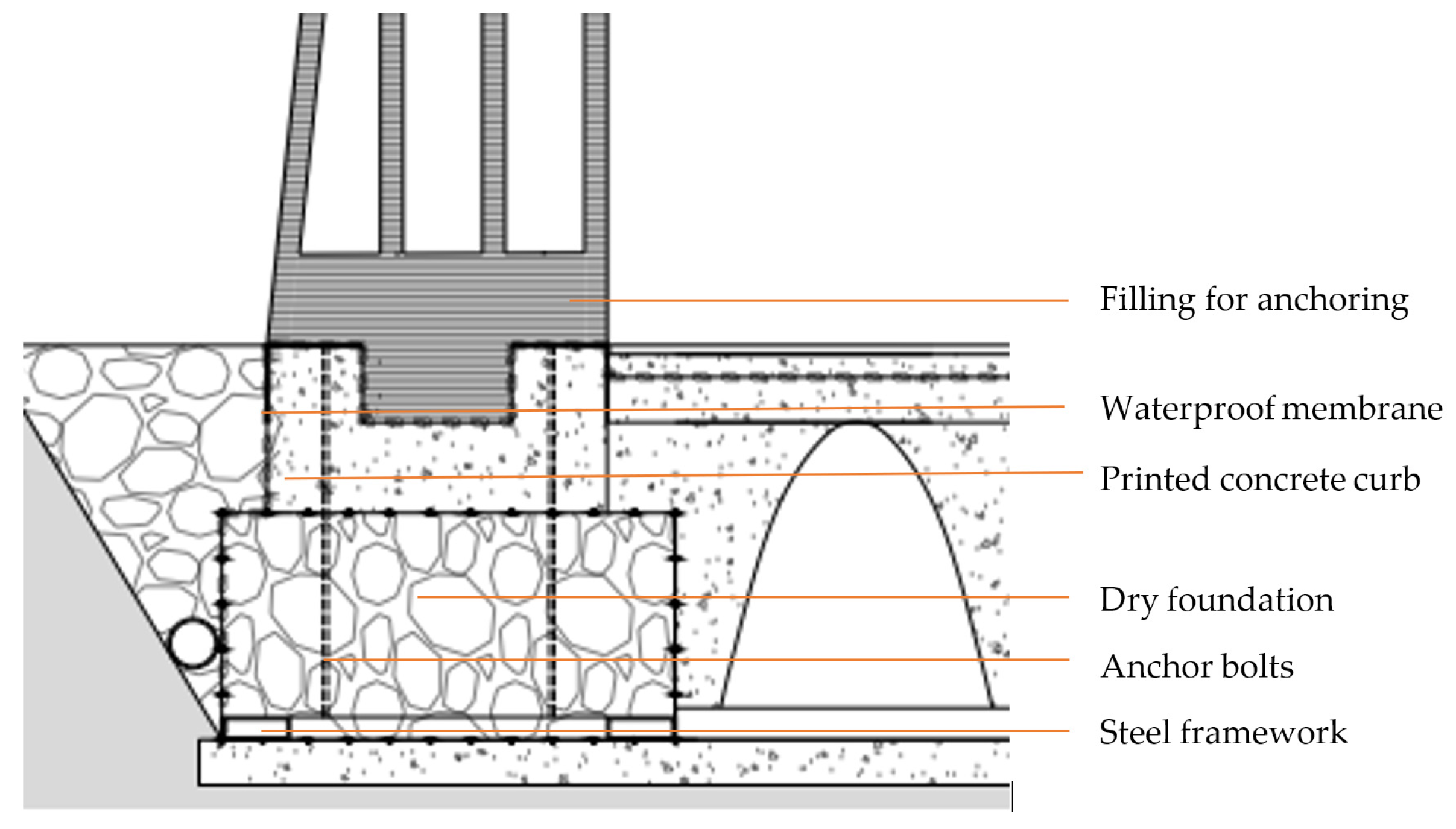
As for the foundations of the houses, an effort was made to reduce the amount of cement used by employing dry foundations (Figure 18). These foundations are made of welded wire-mesh gabions filled with gravel, with a metal frame attached to the bottom panel to which the anchor bolts are connected [41]. The earthen wall is separated from the foundation by a concrete printed curb, connected to the foundation by anchor bolts. The upper end of the curb is shaped with a notch, into which the earthen wall fits, making the wall–foundation systems united. The printing of the wall starts above the ground level and is separated from the curb with a waterproof membrane, to prevent both contact with the soil and potential water infiltration. The floor slab is in contact with the ground; however, an aerated crawl space is printed in concrete to allow air circulation within the wall.
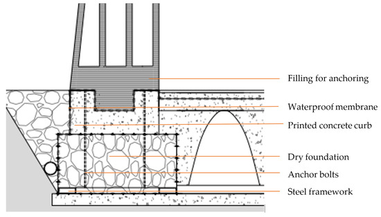
Figure 18.
Detail of perimeter-wall foundation.
Comparison with Previous Design Choices of Expansion through Modular Replication
The idea behind the previous prototypes of 3D-printed houses and this project can at first look similar, with the module definition and aggregation being the key aspects of the projects, but the approach is radically different. In Gaia or Tecla the modules defined are always the same, and although this can ensure an easier design phase, it rises issues regarding the actual quality of the space designed. In a real-life scenario, different communities will have different needs, and defining a housing solution with just one type of module can lead to the creation of repetitive spaces, which are not optimal solutions for the necessities of the inhabitants. In particular, in Gaia, the problem of aggregation is not studied at all. Even if there is an innovative construction solution, the architectural concept is very traditional and more suitable for standalone houses, where every residential unit is separated from the adjacent ones. There is no variety among the housing solutions, resulting in poor customization and alienating spaces. Tecla took a step forward: the relations between the different units are studied, each module can be built following a strict hexagonal grid (Figure 19), and the space between the houses become outdoor communal areas. However, there is still no variations between the spaces that define the house, and the aggregation is subordinated to the printer grid.
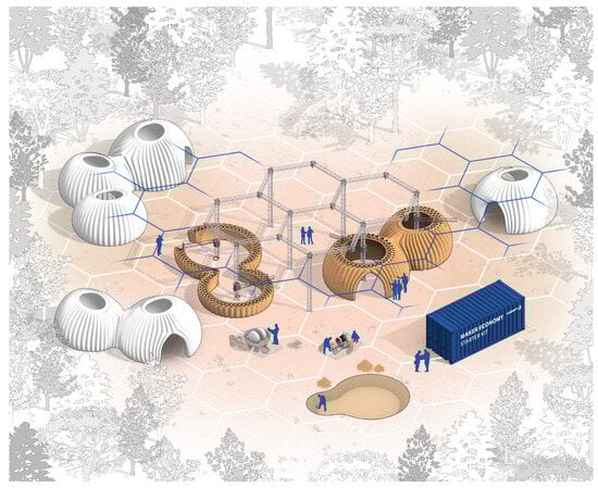
Figure 19.
Tecla construction-method scheme [42].
In this project there is a profound shift, in that module definition is essential but the creation of the community is the priority. The module itself exists to define the house and the latter to develop the aggregation. The project focuses on developing a settlement idea that is not limited to the single housing unit [43], which is the private domain of the family, but can be defined as an aggregative system of parts, where we find a constant dialogue between private and common spaces, between the individual and the community. The idea is that the project has to follow the needs of the inhabitants, and adapt. The first assumption is that different rooms require modules with different sizes, both in plan and section. In this way, not only will the space designed satisfy the needs of the inhabitants, but it will also create variations in the settlement. This variation in size also helps to create a hierarchy between the areas designed, where we can clearly read the presence of private spaces, family spaces and community spaces, with different degrees of privacy:
- -
- Spaces of an individual nature, such as bedrooms and bathrooms;
- -
- Spaces of the family, such as the living room, kitchen, and patios;
- -
- Spaces of the community, such as the central area of the aggregation.
Flexibility is the key to the project; in contrast with the ones previously studied, here the utilization of robotic arms leads to an open-plan aggregation that is free from any grid, and that reflects the spontaneous growth of the community. The system defined develops around the alternation of indoor and outdoor spaces, and, in this way, in contrast to the previous prototypes referenced, the outdoor space becomes an active part of the project, and its presence can vary depending on the lifestyle of the inhabitants.
The exteriors gain fundamental importance and influence the design of the covered spaces; in fact, all the covered rooms are arranged around an open core. This occurs on two scales, the first at the level of the dwelling and the second at the level of aggregation.
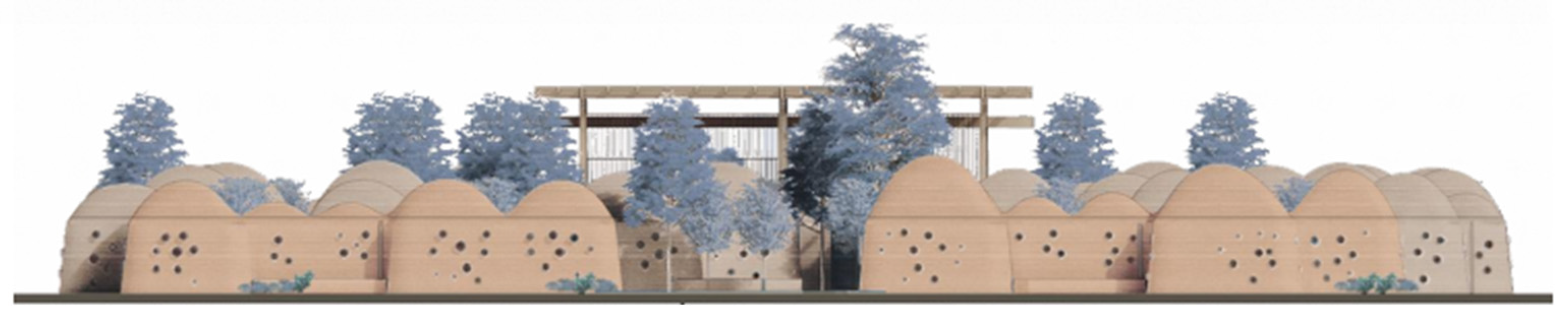
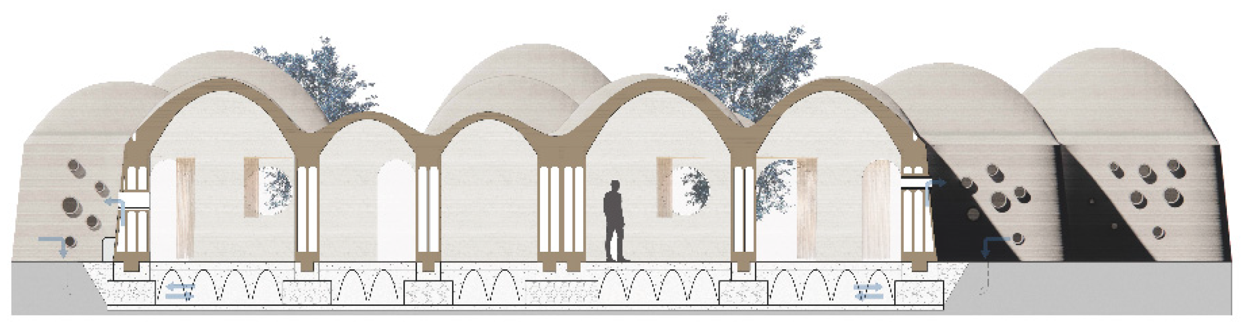
From the elevation (Figure 20) and the section (Figure 21), we can read the elevation configuration of the blocks. The roof-base level is the same for all the units, regardless of size, but the roof height varies with the plan size of the module. This allows for a dual characterization of living spaces, the first characterization being covered—open and the second based on different internal heights. We can also observe the difference in the perforations that open onto the street fronts and those inside: both are designed according to the same principle, that is, to be made directly during the printing phase. However, the former are small and very dense, while the latter are fewer in number and larger in size. Regarding the wall, we see how it is connected in the foundation to channels that allow for ventilation (Figure 22), maintaining proper internal comfort and preventing overheating.

Figure 20.
Southwest elevation.
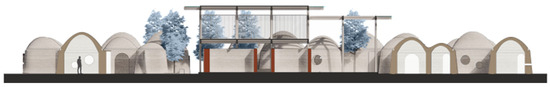
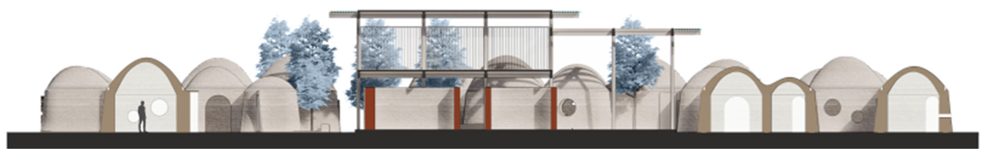
Figure 21.
Section A-A’ (Figure 15).
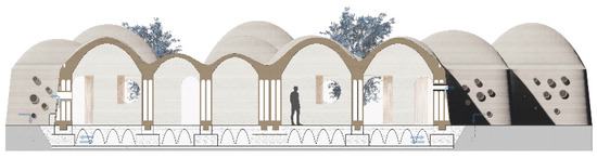
Figure 22.
Section B-B’ (Figure 17) with air recirculation.
It should be emphasized that the realization of the settlement through 3D printing allows the possibility of customizing functional blocks according to the needs of the inhabitants, opening up new possibilities for participatory design, and adapting the project as best as possible to the needs of the community. Given the extreme flexibility of the construction process, it should be specified that the one shown in Figure 15 is only one possible aggregation of the units, but the same design process could be replicated to define linear, terraced, or block typologies.
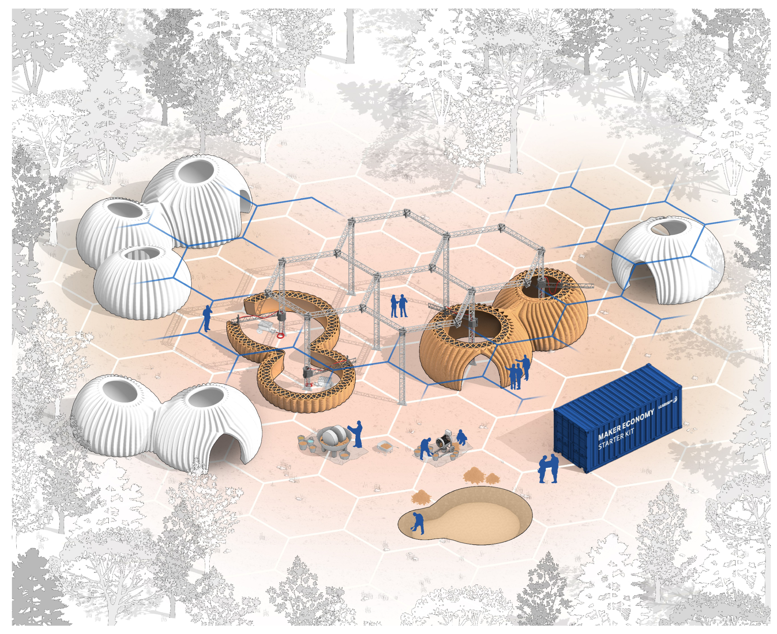
The project is conceived with a view to programmed expansion. As for the houses, each one is built by three robotic arms that operate together. This aspect, in particular, is new compared to the previous 3D-printed housing prototypes. Most of the projects previously shown and used as references are built with a single printer; simultaneous extrusion-arm technology is a technique that was first used in Tecla (Figure 19), where two printers worked at the same time, and nowadays it is still the only building where this printing method was involved.
Furthermore, in this project the construction method is an evolution of the one we saw in Tecla; due to the aggregation and size of the houses, three robotic arms are necessary to cover the area of the entire floor plan, which also ensure bigger housing units and quicker printing time (Figure 23). The positioning of the arms is facilitated by the presence of internal courtyards, which are utilized during the construction phases. In this way, the walls and roofs are raised simultaneously, ensuring proper bonding. Each house is therefore independent from the adjacent ones, so that they can be built in distinct temporal phases. A planned expansion of the aggregate is therefore foreseen in four temporal phases (Figure 24), starting from phase one where we see the construction of the central block, so that it can be immediately used by the inhabitants of the nearby compounds. Subsequently, in phases two to four, the peripheral dwellings will be executed.
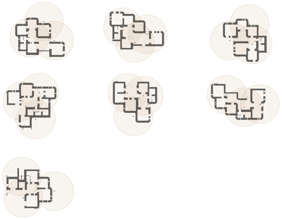
Figure 23.
Positioning of arms for housing printing.
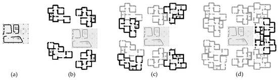
Figure 24.
Settlement printing phases: (a) Common spaces; (b) ×4 dwellings; (c) ×8 dwellings; (d) ×10 dwellings.
5. Discussion
The system just presented aims to study a possible solution to the current housing crisis, providing a project that has its strengths in being sustainable, customizable and quick to build. All of these aspects can be achieved by connecting an ancient construction material, such as earthen mixtures, with modern digital fabrication technologies applied to architecture. These tools become a direct link between the digital model and the building itself. In this way, architects can take full advantage of parametrical design tools, in order to optimize the shape of the elements of the project, without drastically increasing the complexity of the construction site. As we have previously seen, different optimizations, such as structural optimization, can be implemented in the design process, without impacting the construction phase. Furthermore, with the workflow defined, walls and roofs are designed to be both structure and architecture, with no waste of material, and with this being placed only where it needs to be, by varying the parameters defining the module’s elements.
The project has its roots in the concept of the “0 km house”, already explored in the first prototypes such as Gaia and Tecla, and develops that further. The idea is to design a house that can be built with just the materials found in the construction site, reducing as much as possible CO2 emissions. This can be seen first in Gaia, with a preliminary approach where the walls were made of on-site material; however, the foundations, structure and roof are made of concrete and wooden elements, transported from off-site. Tecla takes a step further, and the modules are entirely made of earthen mixture found on-site, but concrete is still used both in the foundations and in the wall mixture. The project presented reduces as much as possible the use of concrete, as it is heavily impactful in terms of CO2 emissions, and off-site elements. The whole module can be built with robotic arms and an earth-based mixture, which is entirely made of local material, such as earth and wheat fiber. The foundations use concrete just for the top curb, while the rest is made of dry elements assembled on-site. With this approach, CO2 emissions due to material transportation and concrete production can be lowered compared to traditional construction techniques, experimenting a new approach to sustainability in architecture.
The design approach is not static, as in previous modular projects. Here, the module geometry is subordinated to its functions, becoming a white canvas for the inhabitants. All the modules share a common generative principle; however, dimensions, heights, openings and accesses are not fixed, and can be modified to adapt to the needs of the community, which shows the dynamic approach to the project where the housing units are always changing, to create optimal living conditions. As previously said, the use of digital fabrication techniques allows for the building of complex shapes with no complications during the construction process, but in this project there is no complexity for its own sake, as it is the reflection of the intricacy of the relations between inhabitants.
Given the current housing crisis, there is a need for affordable housings now more than before. The necessity of having quick access to new dwellings contrasts with their quality, leading to the construction of repetitive buildings with low spatial interests and which are not suitable for carrying out their functions. In the past, the modularization of the elements was implemented to improve construction speed; however, this also means that there is a low degree of customization of the project. Taking advantage of the modern 3D printing technology can solve this issue, since having different modules or housing units does not affect the construction speed of the aggregation, resulting in a solution where uniqueness does not collide with realization. The construction time of the project is only dependent on the quantity of the material deposited, and it has been estimated that the printing time of one house would be approximately 70 h.
6. Conclusions
This paper presents a design proposal for settlements composed of 3D-printed housing modules made with earthen materials. The project proposal is specifically designed to integrate with the construction traditions and building typologies of the place of settlement, namely Niamey, the capital of Niger. The choice of the settlement location is not accidental, as the main motivation that led to the development of 3D-printing technology in earthen materials is humanitarian: to make available to the disadvantaged populations of the third world a dignified and comfortable housing module, at a very low cost of construction, which can be built entirely with zero-kilometer materials. However, the design flexibility allowed by digitalization makes this design proposal easily adaptable to other contexts and other climate zones. In particular, since the prototypes of 3D-printed buildings with earthen materials made in recent years in Europe seem to show good resistance to continental atmospheric agents, the design proposal presented here is also open to applications in the industrialized world. This may open up new perspectives in the context of the increasingly urgent need to reduce atmospheric CO2 emissions. In fact, 3D-printed buildings with earthen materials have a carbon footprint close to zero, both in terms of the materials used and all related activities of production, transportation and disposal. Moreover, the settlement-scale philosophy of the project presented here allows for the Nearly Zero Emissions requirement to be extended from a single Building (NZEB, as defined in the current directives) to the entire settlement. It is therefore a philosophy that not only meets the current directives, but goes beyond them, involving an even broader environmental perspective.
The studied strategy allows for the design and sizing of the system’s construction elements so that they can meet both structural and spatial requirements, maximizing the automation of the construction process. The designed system, in fact, based on the use of robotic arms that deposit the earthen compound in inclined layers, defines an on-site construction strategy with sustainable materials, where it is possible to use the printer as the main construction tool, ensuring the complete printability of the entire building.
This entails numerous design advantages:
- Speed of construction: the estimated time, considering the amount of material printed for the construction of a house and the printing speed of a modern robotic arm (about 6 dcm3/min), is approximately 70 h using three robotic arms simultaneously.
- Risk reduction during construction phase: in the construction site there would be just the people necessary to operate the printers; a lower number of workers will be reflected in fewer work accidents during construction phase.
- Scalability: the houses are completely autonomous, allowing the entire settlement to be realized in phases, so that the constructed spaces can be used immediately.
- Design flexibility: the defined system is capable of varying based on the functional requirements, increasing the customization of built environments. The project variation occurs on two scales: the module scale (the definition of the choice of the rooms depends on the needs of the inhabitants) and the aggregation scale (the arrangement of the modules can vary based on the urban context, defining different types of housing). Customizations do not increase the construction time of individual houses.
- Sustainability: the printing compound is entirely extractable and manufacturable on-site, reducing pollution due to the transportation and production of construction materials. Moreover, being a natural compound, it is also easily disposable. The earthen mixture is used for most of the construction, with the only exception being the foundation system (where a dry technology was adopted to minimize the use of concrete to just the base course of the walls) and the central wooden block.
- Computational workflow: 3D printing allows the application of modern parametric design systems to one of the oldest building materials, the earth. This allows for the study and realization of forms optimized based on various needs: structural or spatial. The design is therefore based on initial parameters and guided by computational tools. In particular, in the case study, the geometries of the modules were optimized to automate the construction process, while the definition of the wall infill was made to withstand the thrusts of the roof.
The strategy presented has numerous advantages, as previously discussed, but it is also important to understand the downsides of this approach:
- This approach works well for urban areas with low housing density. Given the mechanical resistances of the material, one-story solutions are preferred, and this leads to a lower housing density compared to other solutions developed on multiple stories. Hybrid solutions with an earthen wall and wooden/bamboo roof can be studied in future developments, but this will also affect some of the advantages previously presented, such as construction speed.
- The use of 3D printing technology, as we saw, reduces the number of workers needed during the construction phase, and the same time requires them to have a high level of specialization. This is generally something positive, but specific situations must be considered. For instance, in developing countries where there is a high supply of non-specialized workers, creating highly specific jobs would mean that none of them would be able to work in the construction site at first, and would result in fewer work positions in the industry at a later time.
- Structural elements are thicker compared to traditional construction materials, such as concrete or bricks. As a result, if we consider two blocks, one 3D-printed and one built with traditional techniques, the livable area of the 3D printed one is smaller compared to the other.
7. Future Developments
- Variation in wall strength with the variation in infill: defining different typologies of the wall infill in order to change it according to the different load conditions on the wall.
- Possibility of lightening the roof: designing an infill typology for the roof in order to lower the impact of the vault on the walls. This should greatly improve the design quality of the module in different ways: first, lowering the amount of earthen mixture used to print one module, resulting in thinner walls and a better utilization of the space; second, further decreasing the printing time for each housing unit.
- Future scenarios of participatory design: the vision for the project is designing a housing system that can be easily customized by the people that will live it. Three-dimensional-printing technology allows for a direct connection between the machine and the software. A step forward for the current project would be to understand what other types of functional modules can be designed and how each one of them can be customized by the future owner, creating a catalog. This also implies developing an interface where people can design and request their custom houses, based on their needs.
Author Contributions
Conceptualization, L.G., M.A., E.F. and G.P.; methodology, E.F. and G.P.; software, L.G.; validation, M.A., E.F., and G.P.; formal analysis, M.A., E.F., and G.P.; investigation, L.G.; resources, not applicable; data curation, L.G. and E.F.; writing—original draft preparation, L.G.; writing—review and editing, M.A., E.F., and G.P.; visualization, L.G.; supervision, E.F.; project administration, M.A.; funding acquisition, not applicable. All authors have read and agreed to the published version of the manuscript.
Funding
This research received no external funding.
Data Availability Statement
The original contributions presented in the study are included in the paper, further inquiries can be directed to the corresponding author/s.
Conflicts of Interest
The authors declare no conflicts of interest.
References
- Ratti, C.; Claudel, M. Open Source Architecture; Thames & Hudson: London, UK, 2015; pp. 18–22. [Google Scholar]
- Assunção, J.; Chadha, K.; Vasey, L.; Brumaud, C.; Zea Escamilla, E.B.B.; Gramazio, F.; Kohler, M.; Habert, G. Contribution of production processes in environmental impact of low carbon materials made by additive manufacturing. Autom. Constr. 2024, 165, 105545. [Google Scholar] [CrossRef]
- Paparella, G.; Percoco, M. 3D Printing for Housing. Recurring Architectural Themes. In Proceedings of the International Conference on Technological Imagination in the Green and Digital Transition, Rome, Italy, 30 June–2 July 2022. [Google Scholar]
- Fabbri, A.; Morel, J.C. 10—Earthen materials and constructions. In Nonconventional and Vernacular Construction Materials. Characterisation, Properties and Applications; Harries, K.A., Sharma, B., Eds.; Woodhead Publishing: Sawston, UK, 2016; pp. 273–299. [Google Scholar] [CrossRef]
- Reddy, B.V.V. Earthen Materials and Earthen Structures. In Compressed Earth Block & Rammed Earth Structures. Springer Transactions in Civil and Environmental Engineering (STICEE); Springer: Singapore, 2022; pp. 3–55. [Google Scholar] [CrossRef]
- Skinner, B.; Lalit, R. With Concrete, Less Is More: Demand Changes Can Drive the Future of Zero-Carbon Concrete. Available online: https://rmi.org/with-concrete-less-is-more (accessed on 3 August 2024).
- Member Companies of the Global Cement and Concrete Association (GCCA). The GCCA 2050 Cement and Concrete Industry Roadmap for Net Zero Concrete, 1st ed.; Global Cement and Concrete Association: London, UK, 2021. [Google Scholar]
- Kontovourkis, O.; Tryfonos, G. Robotic 3D clay printing of prefabricated non-conventional wall components based on a parametric-integrated design. Autom. Constr. 2020, 110, 103005. [Google Scholar] [CrossRef]
- UNEP-Hosted Global Alliance for Buildings and Construction (GlobalABC). 2022 Global Status Report for Buildings and Construction: Towards a Zero-Emission, Efficient and Resilient Buildings and Construction Sector; United Nations Environment Programme (UNEP): Nairobi, Kenya, 2022; Available online: https://www.unep.org/resources/publication/2022-global-status-report-buildings-and-construction (accessed on 3 August 2024).
- Gallipoli, D.; Bruno, A.W.; Perlot, C.; Mendes, J. A geotechnical perspective of raw earth building. Acta Geotech. 2017, 12, 463–478. [Google Scholar] [CrossRef]
- Santamouris, M.; Kolokotsa, D. Passive cooling dissipation techniques for buildings and other structures: The state of the art. Energy Build. 2013, 57, 74–94. [Google Scholar] [CrossRef]
- Paquet, E.; Furet, B.; Perrot, A. 3D-Printed Raw Earth Structures to Create in Cities Vegetated Oasis of Coolness. In Proceedings of the Second RILEM International Conference on Earthen Construction (ICEC 2024), Edinburgh, UK, 8–10 July 2024. [Google Scholar]
- Curth, A.; Pearl, N.; Castro-Salazar, A.; Mueller, C.; Sass, L. 3D printing earth: Local, circular material processing, fabrication methods, and Life Cycle Assessment. Constr. Build. Mater. 2024, 421, 135714. [Google Scholar] [CrossRef]
- Apis Cor: We Print Buildings—Construction Can Be Fast, Environmentally Friendly, and Affordable If We Entrust All the Complex Work to Smart Machines. Available online: https://robotplace.io/wp-content/uploads/2020/09/2_5409217366045231559_ApisCor_3D_Printer.pdf (accessed on 2 August 2024).
- Mierzwiński, D.; Łach, M.; Gądek, S.; Lin, W.-T.; Tran, D.H.; Korniejenko, K. A brief overview of the use of additive manufacturing of con-create materials in construction. Acta Innov. 2023, 48, 22–37. [Google Scholar] [CrossRef]
- Mogra, M.; Asaf, O.; Sprecher, A.; Amir, O. Design optimization of 3D printed concrete elements considering buildability. Eng. Struct. 2023, 294, 116735. [Google Scholar] [CrossRef]
- Le, T.T.; Austin, S.A.; Lim, S.; Buswell, R.A.; Law, R.; Gibb, A.G.F.; Thorpe, T. Hardened properties of high-performance printing concrete. Cem. Concr. Res. 2012, 42, 558–666. [Google Scholar] [CrossRef]
- Ferretti, E.; Moretti, M.; Chiusoli, A.; Naldoni, L.; de Fabritiis, F.; Visonà, M. Rice-Husk Shredding as a Means of Increasing the Long-Term Mechanical Properties of Earthen Mixtures for 3D Printing. Materials 2022, 15, 743. [Google Scholar] [CrossRef]
- Bhusal, S.; Sedghi, R.; Hojati, M. Evaluating the Printability and Rheological and Mechanical Properties of 3D-Printed Earthen Mixes for Carbon-Neutral Buildings. Sustainability 2023, 15, 15617. [Google Scholar] [CrossRef]
- Rocha, D.; Faria, P.; Lucas, S.S. Additive Manufacturing of Earth-Based Materials: A Literature Review on Mortar Composition, Extrusion, and Processing Earth. Materials 2024, 17, 202. [Google Scholar] [CrossRef]
- Guamán-Rivera, R.; Martínez-Rocamora, A.; García-Alvarado, R.; Muñoz-Sanguinetti, C.; González-Böhme, L.F.; Auat-Cheein, F. Recent developments and challenges of 3D-printed construction: A review of research fronts. Buildings 2022, 12, 229. [Google Scholar] [CrossRef]
- Chiusoli, A. La Prima Casa Stampata in 3D Generata Con la Terra | Gaia. Available online: https://www.3dwasp.com/casa-stampata-in-3d-gaia/ (accessed on 2 August 2024).
- TECLA—Technology and Clay: The First Eco-Sustainable Housing Prototype 3D Printed from Raw Earth. Available online: https://www.mcarchitects.it/en/projects/tecla-technology-and-clay (accessed on 2 August 2024).
- Severi, A. TOVA Is Spain’s First 3D Printed Building with Crane WASP. Available online: https://www.3dwasp.com/en/tova-3d-printed-building-with-crane-wasp/ (accessed on 3 August 2024).
- Press Kit Gaia 3D Printed House. Available online: https://www.dropbox.com/scl/fo/97tk9yc4pwa6ub6kqjxw9/AE5fVzFDrH9zRhu7YfpC6Ro?rlkey=n6e856x5tg423ylmk08ugrt3k&e=1&dl=0 (accessed on 3 August 2024).
- Anderson, C. Dettaglio: Struttura in Terra Stampata in 3D del Prototipo TECLA, Ravenna. Available online: https://archello.com/it/news/dettaglio-struttura-in-terra-stampata-in-3d-del-prototipo-tecla-ravenna (accessed on 3 August 2024).
- Adobe Dome & Nubian Vault: Construction of a Straw-Clay Block Dome & Vault. Available online: https://caneloproject.com/project/adobe-dome-nubian-vault/ (accessed on 3 August 2024).
- Carneau, P.; Mesnil, R.; Roussel, N.; Baverel, O. An exploration of 3d printing design space inspired by masonry. In Proceedings of the IASS Annual Symposium 2019—Structural Membranes 2019, Barcelona, Spain, 7–10 October 2019. [Google Scholar] [CrossRef]
- Brousek, J.; Petr, T.; Mendricky, R. Displacement Analysis of Large-Scale Robotic Arm for Printing Cement Mortar Using Photogrammetry. Machines 2023, 11, 37. [Google Scholar] [CrossRef]
- Gomaa, M.; Vaculik, J.; Soebarto, V.; Griffith, M.; Jabi, W. Feasibility of 3DP cob walls under compression loads in low-rise construction. Constr. Build. Mater. 2021, 301, 124079. [Google Scholar] [CrossRef]
- Sangma, S.; Tripura, D.D. Compressive and shear strength of cob wallettes reinforced with bamboo and steel mesh. Proc. Inst. Civ. Eng. Struct. Build. 2023, 176, 710–724. [Google Scholar] [CrossRef]
- Carcassi, O.B.; Maierdan, Y.; Akemah, T.; Kawashima, S.; Ben-Alon, L. Maximizing fiber content in 3D-printed earth materials: Printability, mechanical, thermal and environmental assessments. Constr. Build. Mater. 2024, 425, 135891. [Google Scholar] [CrossRef]
- Faleschini, F.; Trento, D.; Masoomi, M.; Pellegrino, C.; Zanini, M.A. Sustainable mixes for 3D printing of earth-based constructions. Constr. Build. Mater. 2023, 398, 132496. [Google Scholar] [CrossRef]
- Fletcher, R.A.; MacKenzie, K.J.; Nicholson, C.L.; Shimada, S. The composition range of aluminosilicate geopolymers. J. Eur. Ceram. Soc. 2005, 25, 1471–1477. [Google Scholar] [CrossRef]
- Songpiriyakij, S.; Kubprasit, T.; Jaturapitakkul, C.; Chindaprasirt, P. Compressive strength and degree of reaction of bio-mass-and fly ash-based geopolymer. Constr. Build. Mater. 2010, 24, 236–240. [Google Scholar] [CrossRef]
- Kabore, A.; Ouellet-Plamondon, C.M. The Impact of Vegetable Fibres on the Shrinkage and Mechanical Properties of Cob Materials. Materials 2024, 17, 736. [Google Scholar] [CrossRef]
- Kabore, A.; Ouellet-Plamondon, C.M. Improved insulation with fibres in heavy cob for building walls. Ind. Crops Prod. 2024, 215, 118626. [Google Scholar] [CrossRef]
- Ferretti, E.; Moretti, M.; Chiusoli, A.; Naldoni, L.; de Fabritiis, F.; Visonà, M. Mechanical Properties of a 3D-Printed Wall Segment Made with an Earthen Mixture. Materials 2022, 15, 438. [Google Scholar] [CrossRef] [PubMed]
- Clarin, M. Plate Buckling Resistance—Patch Loading of Longitudinally Stiffened Webs and Local Buckling. Ph.D. Thesis, Luleå University of Technology, Luleå, Sweden, 2007. [Google Scholar]
- Maja, M.M.; Ayano, S.F. The impact of population growth on natural resources and farmers’ capacity to adapt to climate change in low-income countries. Earth Syst. Environ. 2021, 5, 271–283. [Google Scholar] [CrossRef]
- Fanti, R.; Ferro, E.; Forlati, G.; Gajo, A.; Gerola, M.; Graffer, S.; Menapace, S.; Molinari, M.; Polastri, A.; Rossi, S.; et al. Fondazioni a secco per edifici in legno. Ingenio 2022, 39, 1–40. Available online: https://www.ingenio-web.it/articoli/fondazioni-a-secco-per-edifici-in-legno/ (accessed on 3 August 2024).
- WASP. 3D Printed House TECLA—Eco-Housing. Available online: https://www.dropbox.com/scl/fo/mpp55g7uxzp6vdfui05im/APDjYqpT6dCJ_BzpQPdkpMg/Tecla%202019_Announcement%20Release/images?dl=0&preview=WASP_Tecla_Maker+Economy+Starter+Kit.jpg&rlkey=dp9m20q4bbufjclkohsmptav9&subfolder_nav_tracking=1 (accessed on 1 August 2024).
- Gündüz, G.; Özkar, M. A process-based framework for adaptable modules in robotic clay 3D printing. Int. J. Archit. Comput. 2024, 22, 45–61. [Google Scholar] [CrossRef]


Disclaimer/Publisher’s Note: The statements, opinions and data contained in all publications are solely those of the individual author(s) and contributor(s) and not of MDPI and/or the editor(s). MDPI and/or the editor(s) disclaim responsibility for any injury to people or property resulting from any ideas, methods, instructions or products referred to in the content. |
© 2024 by the authors. Licensee MDPI, Basel, Switzerland. This article is an open access article distributed under the terms and conditions of the Creative Commons Attribution (CC BY) license (https://creativecommons.org/licenses/by/4.0/).