
A Novel DC Electroosmotic Micromixer Based on Helical Vortices
 , , and
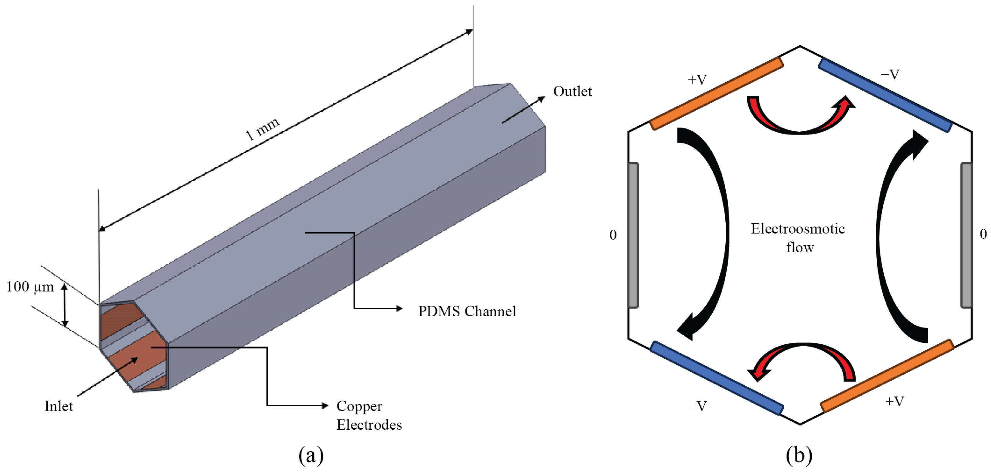
Abstract
:1. Introduction
2. Theoretical Background
2.1. The Physics of DCEO
2.2. Mixing Index
3. Micromixer Design
3.1. Device Topology and Working Principle
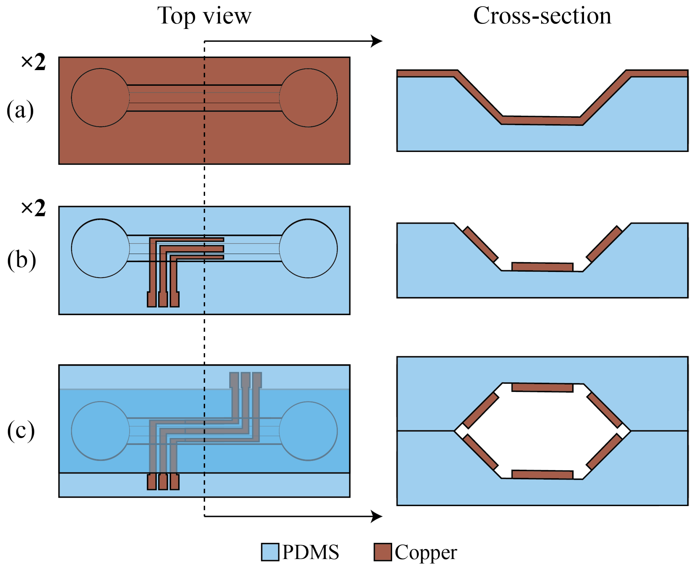
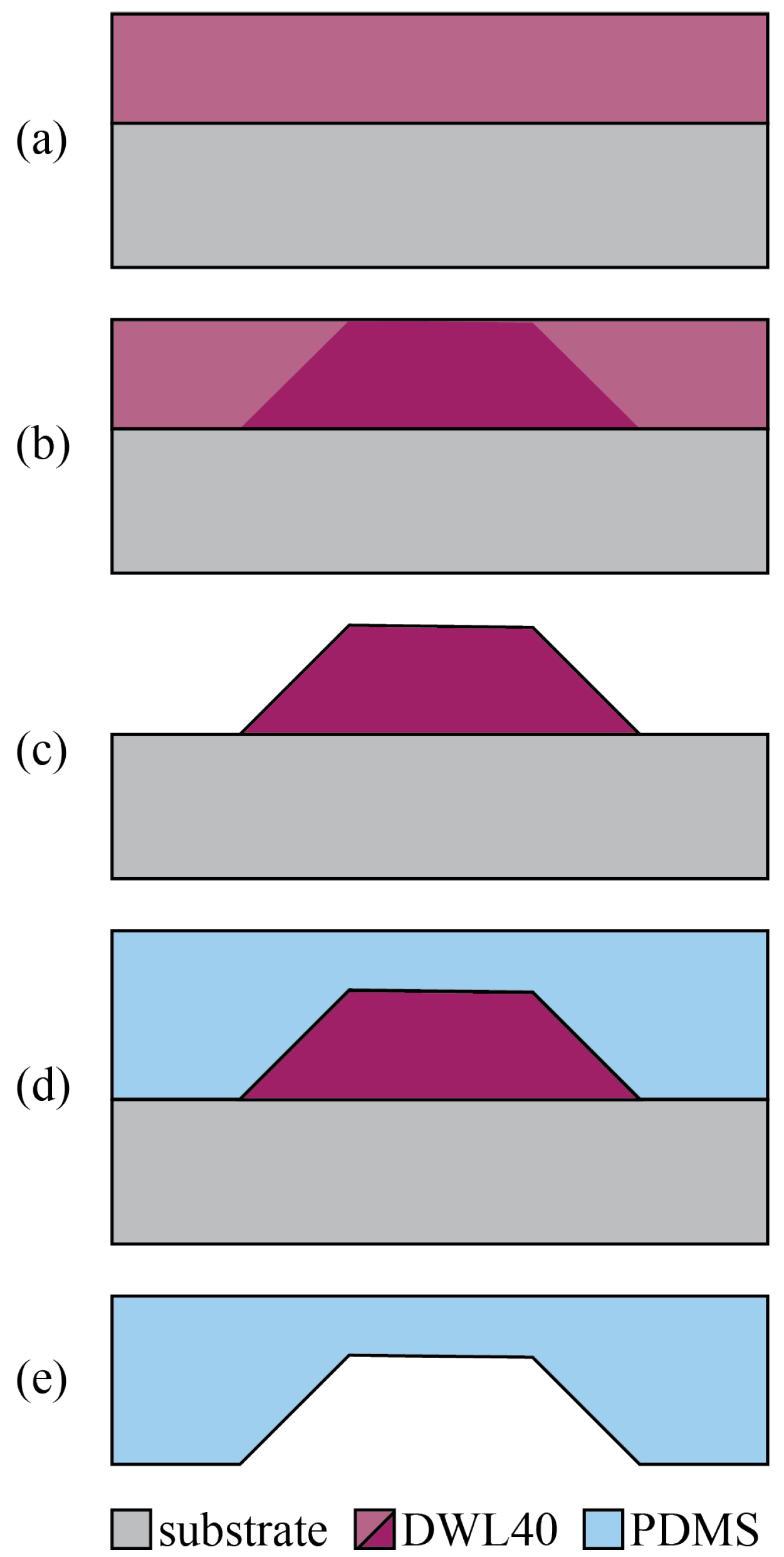
3.2. Fabrication Process
4. Results
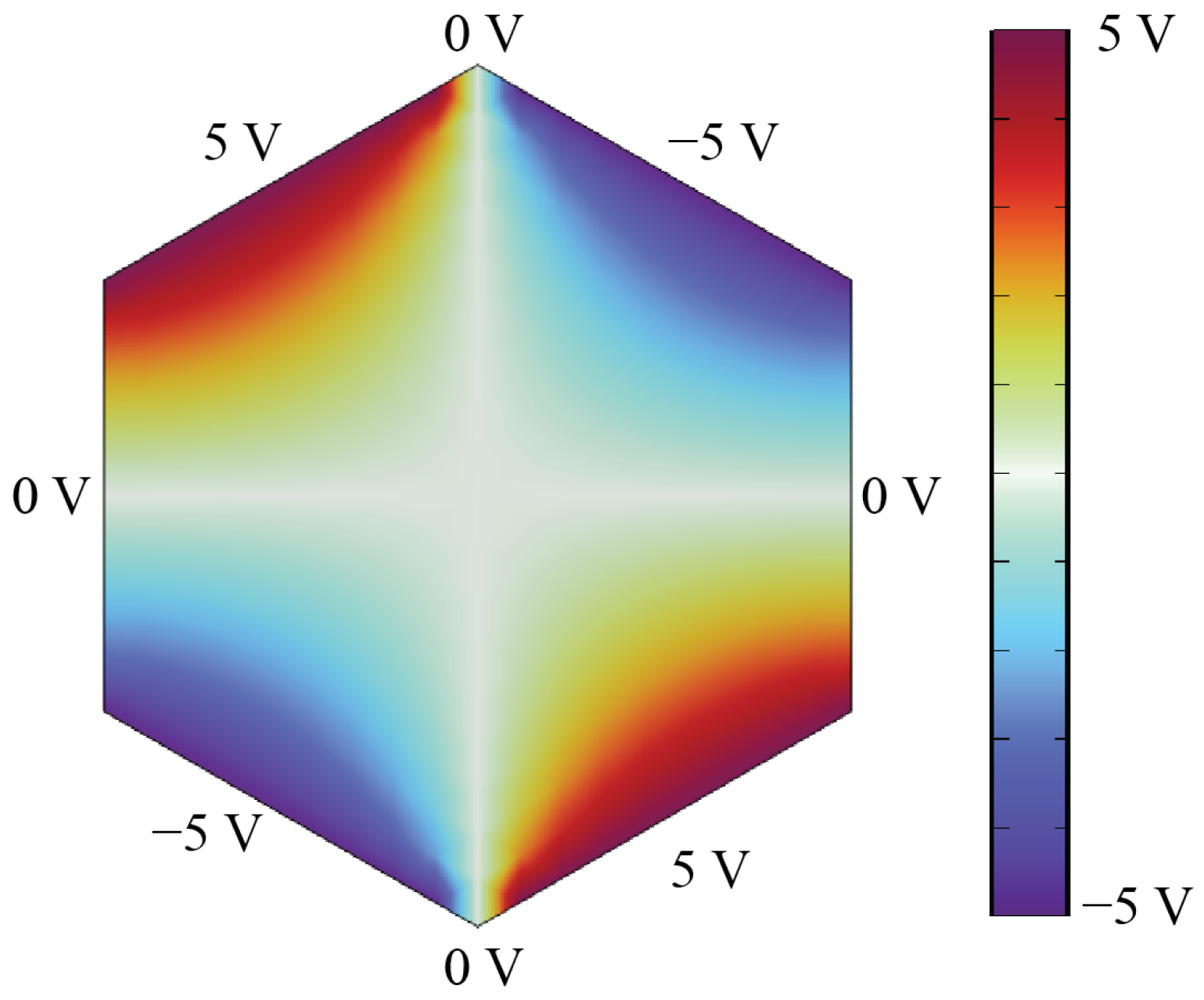
4.1. Initial and Boundary Conditions
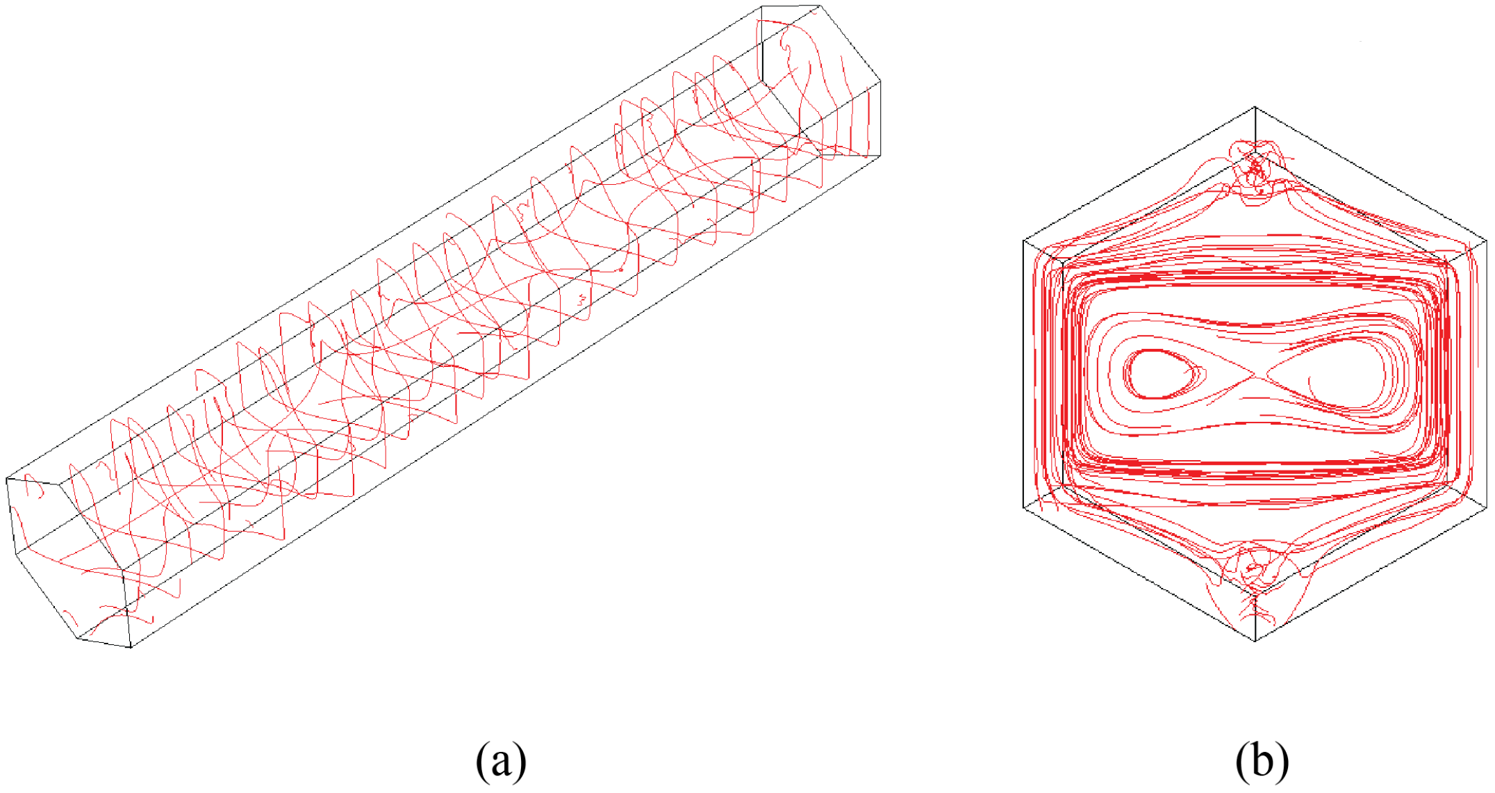
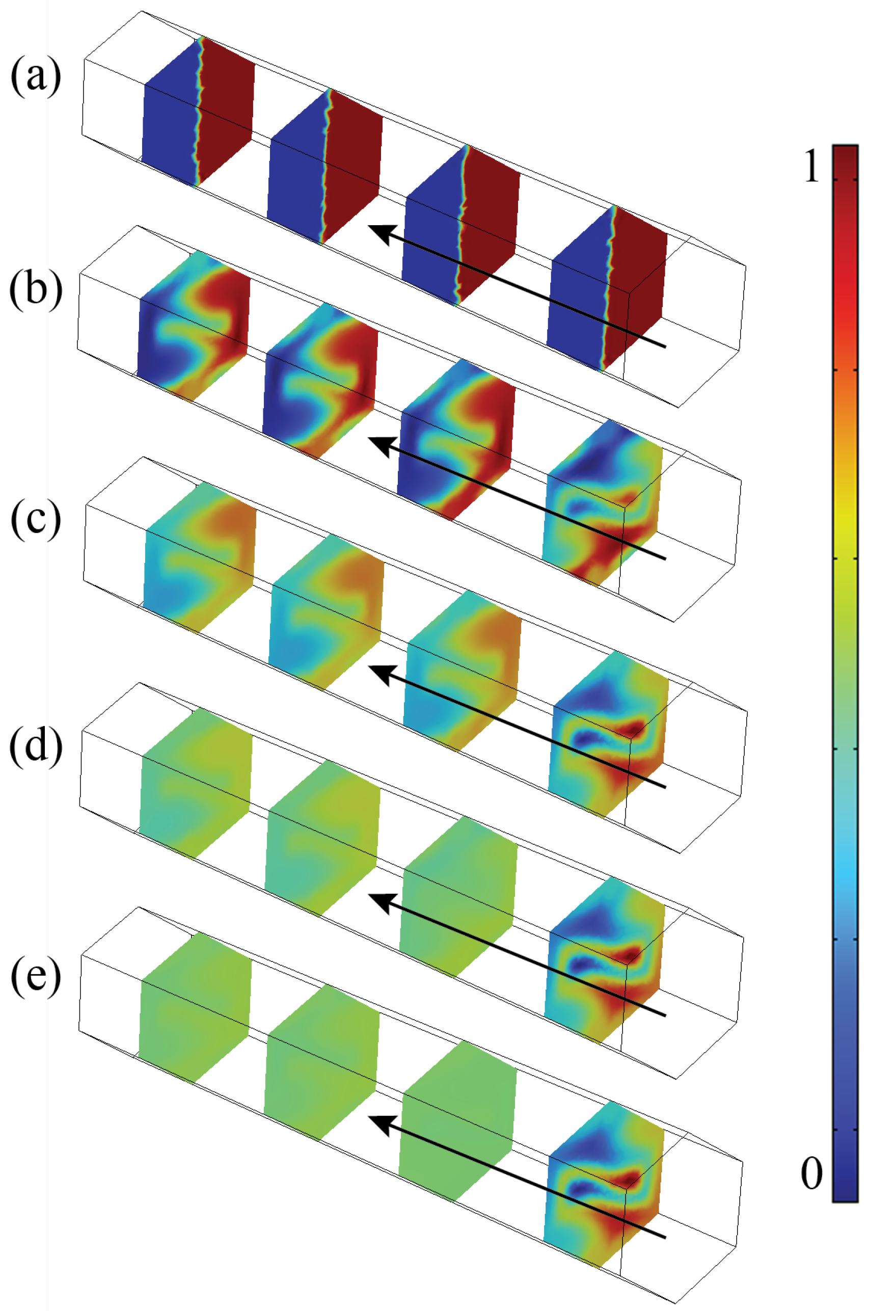
4.2. Vortex Formation and Mixing Action
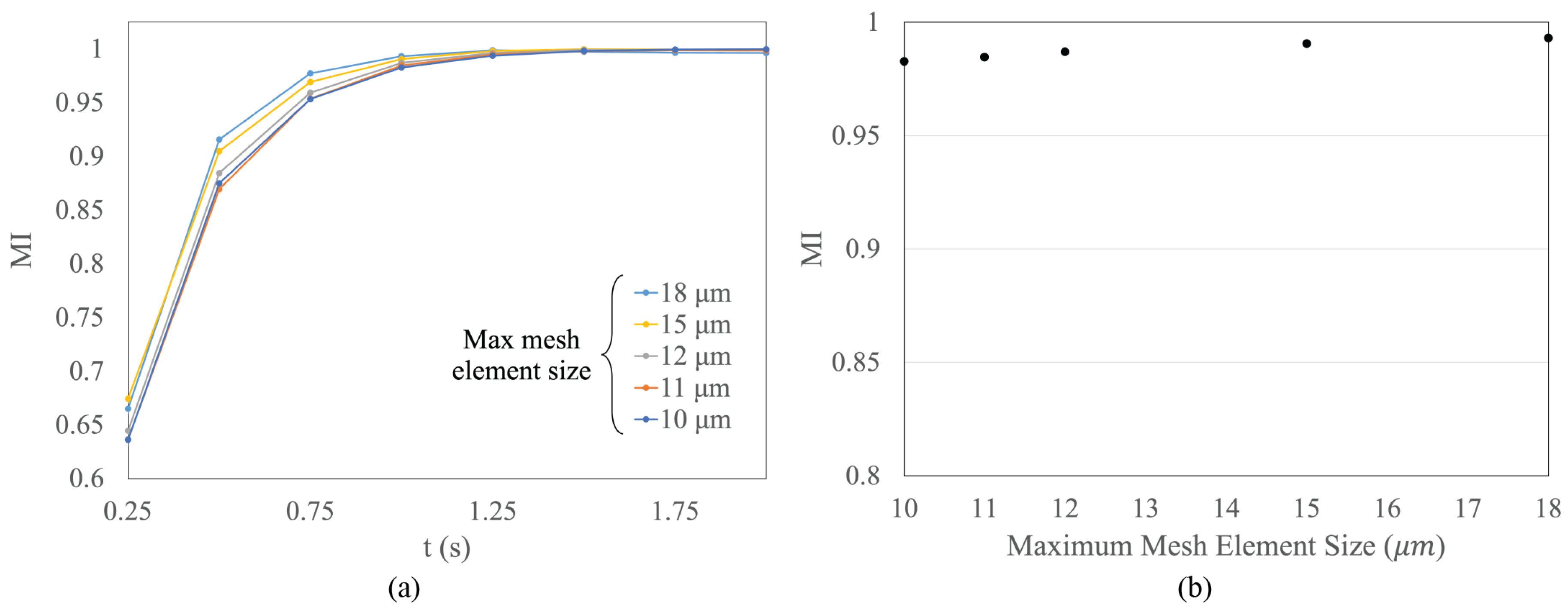
4.3. Model Mesh Independence Assessment
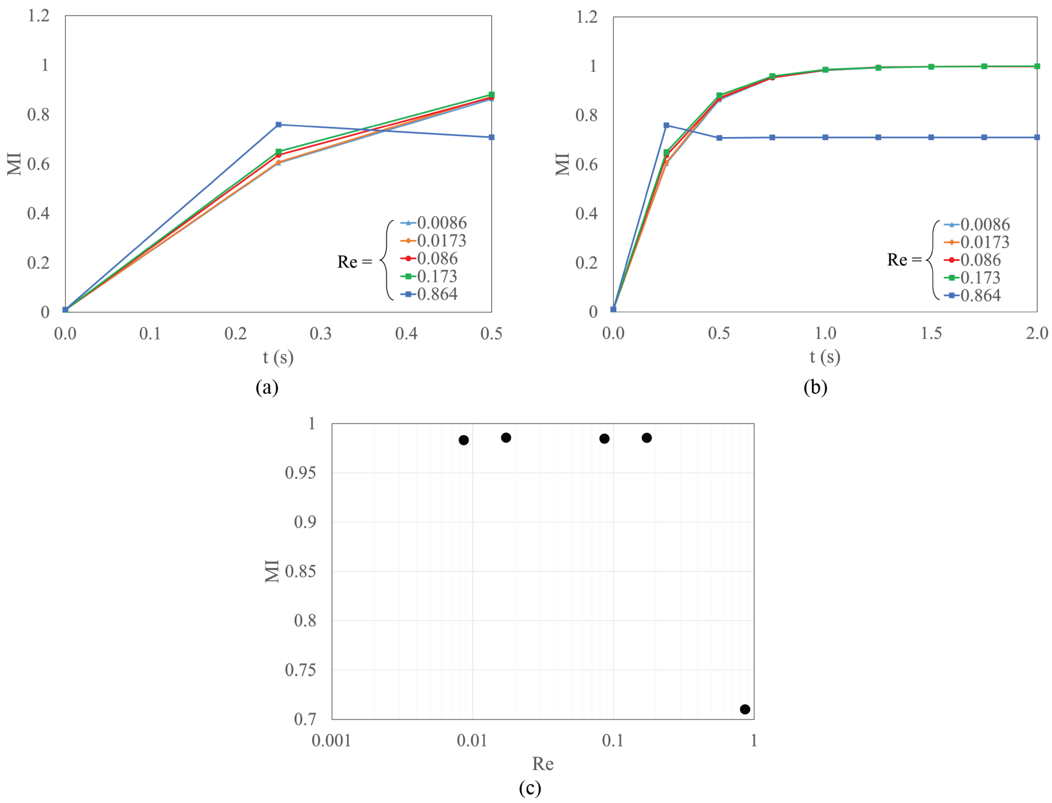
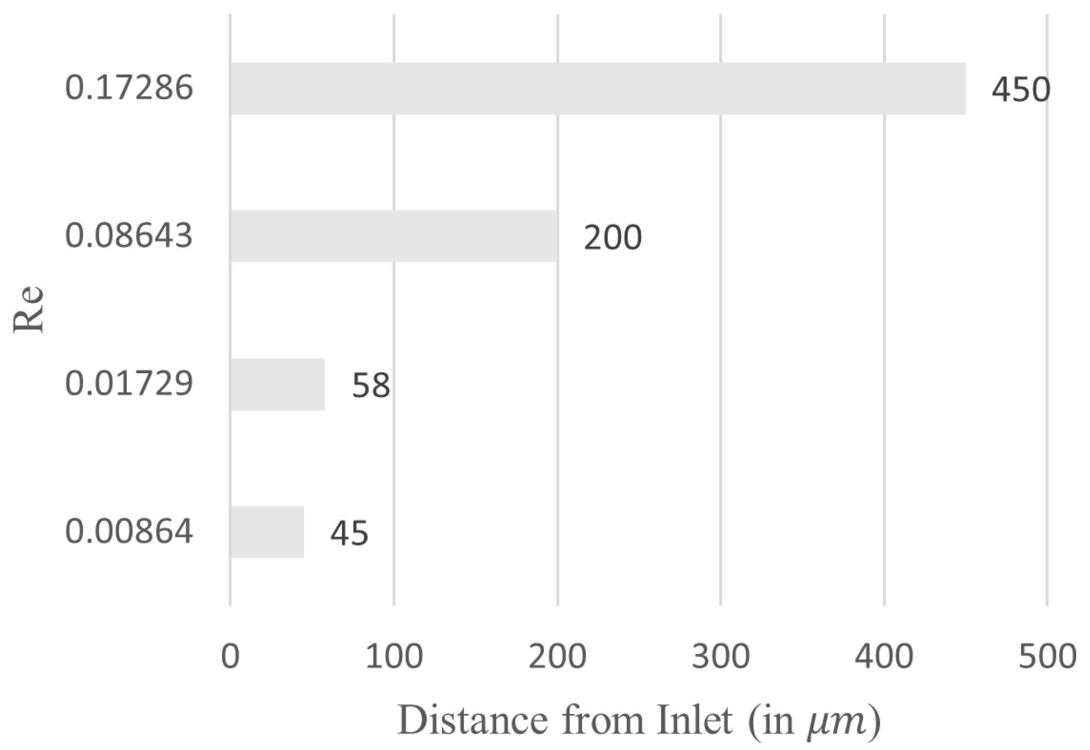
4.4. Effect of the Reynolds Number on Mixing Efficiency
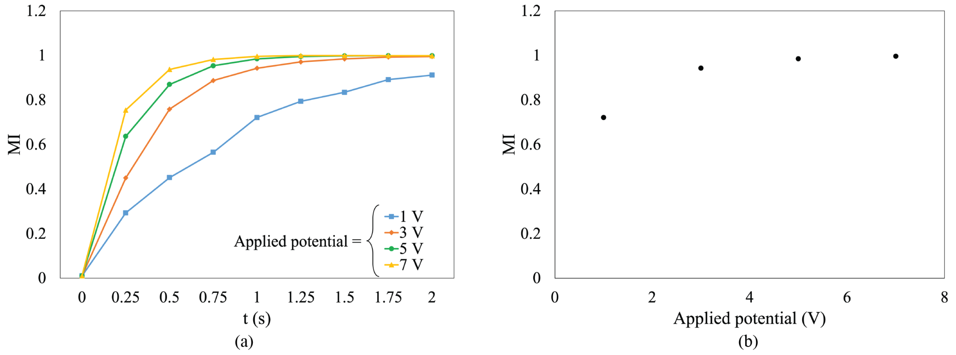
4.5. Effect of the Actuation Potential on Mixing Efficiency
4.6. Effect of Channel Geometry
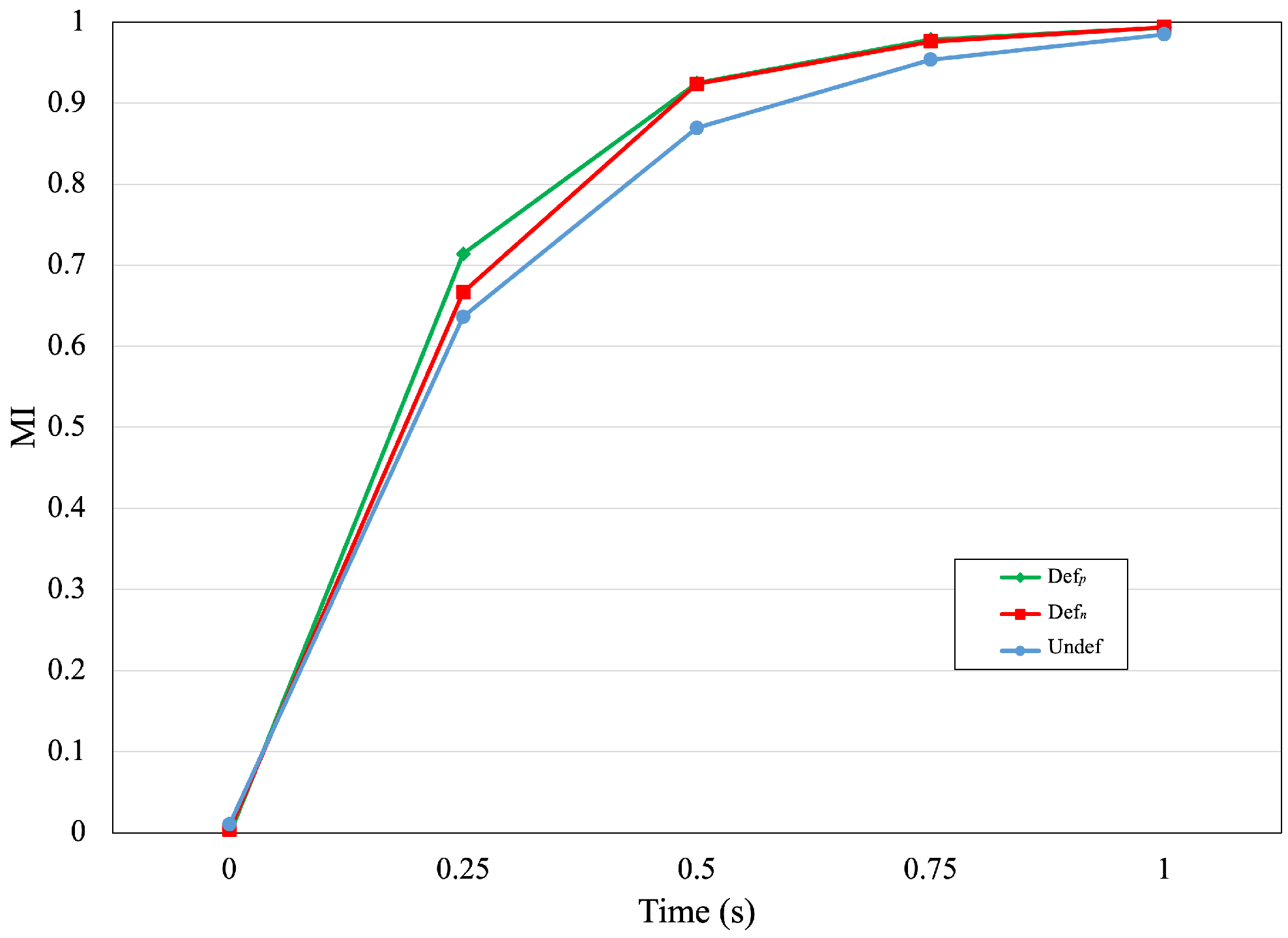
4.7. Effect of Asymmetric Voltage Configuration
5. Discussion
6. Conclusions
Author Contributions
Funding
Institutional Review Board Statement
Informed Consent Statement
Data Availability Statement
Conflicts of Interest
Abbreviations
| a | channel cross-section side length |
| species pointwise concentration | |
| D | liquid diffusion coefficient |
| E | applied electric field |
| F | fluid body force |
| L | characteristic length |
| mixing index | |
| p | fluid pressure |
| Reynolds number | |
| t | time |
| u | fluid velocity |
| electroosmotic slip velocity | |
| degree of mixing | |
| liquid relative permittivity | |
| electric potential | |
| fluid dynamic viscosity | |
| fluid density | |
| concentration standard deviation | |
| channel wall zeta potential |
References
- Narayanamurthy, V.; Jeroish, Z.; Bhuvaneshwari, K.; Bayat, P.; Premkumar, R.; Samsuri, F.; Yusoff, M.M. Advances in passively driven microfluidics and lab-on-chip devices: A comprehensive literature review and patent analysis. RSC Adv. 2020, 10, 11652–11680. [Google Scholar] [CrossRef] [PubMed]
- Roller, R.M.; Sumantakul, S.; Tran, M.; Van Wyk, A.; Zinna, J.; Donelson, D.A.; Finnegan, S.G.; Foley, G.; Frechette, O.R.; Gaetgens, J.; et al. Inquiry-based laboratories using paper microfluidic devices. J. Chem. Educ. 2021, 98, 1946–1953. [Google Scholar] [CrossRef]
- Zhou, W.; Dou, M.; Timilsina, S.S.; Xu, F.; Li, X. Recent innovations in cost-effective polymer and paper hybrid microfluidic devices. Lab Chip 2021, 21, 2658–2683. [Google Scholar] [CrossRef] [PubMed]
- Wang, Y.; Luo, S.; Kwok, H.Y.; Pan, W.; Zhang, Y.; Zhao, X.; Leung, D.Y. Microfluidic fuel cells with different types of fuels: A prospective review. Renew. Sustain. Energy Rev. 2021, 141, 110806. [Google Scholar] [CrossRef]
- Tanveer, M.; Lim, E.S.; Kim, K.Y. Effects of channel geometry and electrode architecture on reactant transportation in membraneless microfluidic fuel cells: A review. Fuel 2021, 298, 120818. [Google Scholar] [CrossRef]
- Saravanakumar, S.M.; Cicek, P.V. Microfluidic Mixing: A Physics-Oriented Review. Micromachines 2023, 14, 1827. [Google Scholar] [CrossRef] [PubMed]
- Salari, A.; Navi, M.; Lijnse, T.; Dalton, C. AC electrothermal effect in microfluidics: A review. Micromachines 2019, 10, 762. [Google Scholar] [CrossRef]
- Alizadeh, A.; Hsu, W.L.; Wang, M.; Daiguji, H. Electroosmotic flow: From microfluidics to nanofluidics. Electrophoresis 2021, 42, 834–868. [Google Scholar] [CrossRef]
- Chen, Z.; Wang, Y.; Zhou, S. Numerical Analysis of Mixing Performance in an Electroosmotic Micromixer with Cosine Channel Walls. Micromachines 2022, 13, 1933. [Google Scholar] [CrossRef]
- Modarres, P.; Tabrizian, M. Phase-controlled field-effect micromixing using AC electroosmosis. Microsyst. Nanoeng. 2020, 6, 60. [Google Scholar] [CrossRef]
- Chen, Y.; Lv, Z.; Wei, Y.; Li, J. Mixing performance of the induced charge electro-osmosis micromixer with conductive chamber edges for viscoelastic fluid. Phys. Fluids 2022, 34, 083110. [Google Scholar] [CrossRef]
- Chen, Y.; Li, J.; Lv, Z.; Wei, Y.; Li, C. Mixing performance of viscoelastic fluids in an induced charge electroosmotic micromixer with a conductive cylinder. J. Non-Newton. Fluid Mech. 2023, 317, 105047. [Google Scholar] [CrossRef]
- Gönül, A.; Okbaz, A.; Kayaci, N.; Dalkilic, A.S. Flow optimization in a microchannel with vortex generators using genetic algorithm. Appl. Therm. Eng. 2022, 201, 117738. [Google Scholar] [CrossRef]
- Wang, J.; Yu, K.; Ye, M.; Wang, E.; Wang, W.; Sundén, B. Effects of pin fins and vortex generators on thermal performance in a microchannel with Al2O3 nanofluids. Energy 2022, 239, 122606. [Google Scholar] [CrossRef]
- Shen, S.; Gao, M.; Zhang, F.; Niu, Y. Numerical study of multivortex regulation in curved microchannels with ultra-low-aspect-ratio. Micromachines 2021, 12, 81. [Google Scholar] [CrossRef] [PubMed]
- Helmers, T.; Kemper, P.; Thöming, J.; Mießner, U. The flow topology transition of liquid–liquid Taylor flows in square microchannels. Exp. Fluids 2022, 63, 5. [Google Scholar] [CrossRef]
- Aubin, J.; Ferrando, M.; Jiricny, V. Current methods for characterising mixing and flow in microchannels. Chem. Eng. Sci. 2010, 65, 2065–2093. [Google Scholar] [CrossRef]
- Mariotti, A.; Galletti, C.; Mauri, R.; Salvetti, M.; Brunazzi, E. Effect of stratification on the mixing and reaction yield in a T-shaped micro-mixer. Phys. Rev. Fluids 2021, 6, 024202. [Google Scholar] [CrossRef]
- Wu, M.; Gao, Y.; Ghaznavi, A.; Zhao, W.; Xu, J. AC electroosmosis micromixing on a lab-on-a-foil electric microfluidic device. Sens. Actuators B Chem. 2022, 359, 131611. [Google Scholar] [CrossRef]
- Antognoli, M.; Masoni, S.T.; Mariotti, A.; Mauri, R.; Brunazzi, E.; Galletti, C. Investigation on steady regimes in a X-shaped micromixer fed with water and ethanol. Chem. Eng. Sci. 2022, 248, 117254. [Google Scholar] [CrossRef]
- Ryspayeva, A.; Jones, T.D.; Esfahani, M.N.; Shuttleworth, M.P.; Harris, R.A.; Kay, R.W.; Desmulliez, M.P.; Marques-Hueso, J. A rapid technique for the direct metallization of PDMS substrates for flexible and stretchable electronics applications. Microelectron. Eng. 2019, 209, 35–40. [Google Scholar] [CrossRef]
- Zhang, D.; Yang, J.; Hirai, Y.; Kamei, K.i.; Tabata, O.; Tsuchiya, T. Microfabrication of polydimethylsiloxane–parylene hybrid microelectrode array integrated into a multi-organ-on-a-chip. Jpn. J. Appl. Phys. 2022, 62, 017002. [Google Scholar] [CrossRef]
- Scott, S.M.; Ali, Z. Fabrication methods for microfluidic devices: An overview. Micromachines 2021, 12, 319. [Google Scholar] [CrossRef] [PubMed]
- Niculescu, A.G.; Chircov, C.; Bîrcă, A.C.; Grumezescu, A.M. Fabrication and applications of microfluidic devices: A review. Int. J. Mol. Sci. 2021, 22, 2011. [Google Scholar] [CrossRef] [PubMed]
- Williams, K.R.; Gupta, K.; Wasilik, M. Etch rates for micromachining processing-Part II. J. Microelectromech. Syst. 2003, 12, 761–778. [Google Scholar] [CrossRef]
- Hadjigeorgiou, A.G.; Boudouvis, A.G.; Kokkoris, G. Thorough computational analysis of the staggered herringbone micromixer reveals transport mechanisms and enables mixing efficiency-based improved design. Chem. Eng. J. 2021, 414, 128775. [Google Scholar] [CrossRef]
- Zhao, Q.; Yuan, D.; Tang, S.Y.; Yun, G.; Yan, S.; Zhang, J.; Li, W. Top sheath flow-assisted secondary flow particle manipulation in microchannels with the slanted groove structure. Microfluid. Nanofluid. 2019, 23, 6. [Google Scholar] [CrossRef]
- Wang, X.; Liu, Z.; Cai, Y.; Wang, B.; Luo, X. A cost-effective serpentine micromixer utilizing ellipse curve. Anal. Chim. Acta 2021, 1155, 338355. [Google Scholar] [CrossRef] [PubMed]
- Herreros, I.; Hochberg, D. Chiral symmetry breaking and entropy production in Dean vortices. Phys. Fluids 2023, 35, 043614. [Google Scholar] [CrossRef]
- Zhao, X.; Chen, H.; Xiao, Y.; Zhang, J.; Qiu, Y.; Wei, J.; Hao, N. Rational design of robust flower-like sharp-edge acoustic micromixers towards efficient engineering of functional 3D ZnO nanorod array. Chem. Eng. J. 2022, 447, 137547. [Google Scholar] [CrossRef]
- Le, N.H.A.; Deng, H.; Devendran, C.; Akhtar, N.; Ma, X.; Pouton, C.; Chan, H.K.; Neild, A.; Alan, T. Ultrafast star-shaped acoustic micromixer for high throughput nanoparticle synthesis. Lab Chip 2020, 20, 582–591. [Google Scholar]
- Huang, P.H.; Xie, Y.; Ahmed, D.; Rufo, J.; Nama, N.; Chen, Y.; Chan, C.Y.; Huang, T.J. An acoustofluidic micromixer based on oscillating sidewall sharp-edges. Lab Chip 2013, 13, 3847–3852. [Google Scholar] [CrossRef] [PubMed]
- Ghorbani Kharaji, Z.; Kalantar, V.; Bayareh, M. Acoustic sharp-edge-based micromixer: A numerical study. Chem. Pap. 2022, 76, 1721–1738. [Google Scholar] [CrossRef]
- Marin, A.; Rossi, M.; Rallabandi, B.; Wang, C.; Hilgenfeldt, S.; Kähler, C.J. Three-dimensional phenomena in microbubble acoustic streaming. Phys. Rev. Appl. 2015, 3, 041001. [Google Scholar] [CrossRef]
- Jalal, J.; Leong, T.S. Microstreaming and its role in applications: A mini-review. Fluids 2018, 3, 93. [Google Scholar] [CrossRef]


Disclaimer/Publisher’s Note: The statements, opinions and data contained in all publications are solely those of the individual author(s) and contributor(s) and not of MDPI and/or the editor(s). MDPI and/or the editor(s) disclaim responsibility for any injury to people or property resulting from any ideas, methods, instructions or products referred to in the content. |
© 2024 by the authors. Licensee MDPI, Basel, Switzerland. This article is an open access article distributed under the terms and conditions of the Creative Commons Attribution (CC BY) license (https://creativecommons.org/licenses/by/4.0/).
Share and Cite
Saravanakumar, S.M.; Jamshidi Seresht, M.; Izquierdo, R.; Cicek, P.-V. A Novel DC Electroosmotic Micromixer Based on Helical Vortices. Actuators 2024, 13, 139. https://doi.org/10.3390/act13040139
Saravanakumar SM, Jamshidi Seresht M, Izquierdo R, Cicek P-V. A Novel DC Electroosmotic Micromixer Based on Helical Vortices. Actuators. 2024; 13(4):139. https://doi.org/10.3390/act13040139
Chicago/Turabian StyleSaravanakumar, Sri Manikandan, Mohsen Jamshidi Seresht, Ricardo Izquierdo, and Paul-Vahe Cicek. 2024. "A Novel DC Electroosmotic Micromixer Based on Helical Vortices" Actuators 13, no. 4: 139. https://doi.org/10.3390/act13040139