Article

Investigation on an Improved Household Refrigerator for Energy Saving of Residential Buildings

1
Department of Thermal Science and Energy Engineering, University of Science and Technology of China, Hefei 230027, China
2
Department of Building Services Engineering, The Hong Kong Polytechnic University, Kowloon, Hong Kong, China
3
Department of Architecture and Built Environment, University of Nottingham, University Park, Nottingham NG7 2RD, UK
*
Authors to whom correspondence should be addressed.
Appl. Sci. 2020, 10(12), 4246; https://doi.org/10.3390/app10124246
Submission received: 27 April 2020 / Revised: 25 May 2020 / Accepted: 29 May 2020 / Published: 20 June 2020
(This article belongs to the Special Issue Progress on Sustainable Energy Technologies for Building Applications)

Abstract

:
The efficiency improvement of household refrigerators is of significance to electricity consumption reduction of residential buildings. The cold loss recovery in household refrigerators is a promising development direction. In this study, a refrigerator improved by heat pipes is designed to reduce the cold loss at freezer walls to enhance the overall efficiency of the refrigerator. A complete steady-state mathematical model is built for characterizing its overall energy saving behaviors by introducing the real structural parameters of a Midea BCD-111 refrigerator and measured temperature boundary conditions. The performances of the improved refrigerator are investigated with typical operating states, variable ambient temperature, and heat pipe design. The simulative results indicate that the cold loss of the freezer of the improved refrigerator can be reduced by 8.3–16.5%, and the energy saving capability is relatively reliable. Results verify that the cold loss recovery of the improved refrigerator is feasible in various operating conditions.

1. Introduction

Worldwide demands for living quality grow rapidly with social and economic development [1], which leads to a considerable increase in domestic appliances in buildings [2]. As a representative, the popularity of household refrigerators prevents the reduction of the world’s energy demand and CO2 emissions, and its energy consumption is accounting for more than a quarter of the global residential electricity demand [3]. Thus, promoting new and efficient technologies for the efficiency advance in household refrigerators is extremely urgent. Great efforts have been made to enhance the performances of the key components, such as the compressor [4], the condenser, and the evaporator [5], to optimize the refrigeration cycle [6], to modify internal and external structural design [7], and to improve the thermal insulated behaviors [8]. However, there still exists a balance between cost and performance in the research field of household refrigerators [9]. Recently, an increasing number of new technologies have been applied for breaking this chain. Cheng et al. designed a heat storage evaporator and cold storage condenser for a household refrigerator, and its energy saving ratio was 32% [10]. Clito et al. enhanced the heat dissipation of a household refrigerator. The surface temperature close to the compressor was reduced by 11 °C [11]. Liu et al. proposed to adopt a diffuser pipe to enhance the behavior of a normal refrigerator, which leads to a 3.36–4.09% reduction in power consumption [12]. Cao et al. conducted a preliminarily experimental study on a cool-storage refrigerator for the use of peak load shifting [13]; the follow-up research focused on the temperature management enhancement of household refrigerator [14]. Söylemez et al. used a hybrid cooling system to reduce cooling times and improve temperature stability of a household refrigerator [15]. Fatouh et al. suggested utilizing a ternary hydrocarbon mixture for household refrigerators and analyzed its energy and exergy behaviors in details [16]. Certain achievements have been made by the above attempts; however, the potential of a household refrigerator in its cold loss recovery did not arouse enough attention [17].
In a conventional household refrigerator, the temperature of the freezer is much lower than that of the fresh food compartment, and the only evaporating temperature of its cooling cycle is determined by the former. If the wasted cold energy of the freezer can be partly reused by the fresh food compartment, the overall energy consuming amount of the refrigerator is reduced while no additional exergy loss is generated. In our last study, this basic ideal was performed by utilizing the efficient heat transfer capability of two-phase loop thermosyphons to separate cold loss from the interlayer of the isolation wall of the freezer to the fresh food compartment [18]. In comparison to increasing the wall thickness, there was no reduction in the usable space of freezer by adopting this novel cold loss reduction method, and the cost increment of the improved refrigerator was relatively low, since the main structure of two-phase loop thermosyphons is made by low-cost aluminum alloy. Preliminary numerical research on the cold loss reduction behaviors of the modified freezer walls was performed in fixed operating conditions of an imaginary refrigerator, and results proved the effectiveness of heat pipes in the energy saving of household refrigerators. However, the overall energy saving capability is unknown, and the accuracy of quantitative analysis is still insufficient. Derived research focused on radical structural change of a household refrigerator, which deviates from the original intention of saving energy through simple structural improvement [19]. In the current research, new structure design of the refrigerator with heat pipes is proposed, a complete steady-state mathematical model is built for characterizing its overall energy saving behaviors, the real structural parameters of the Midea BCD-111 refrigerator and measured temperature boundary conditions are adopted for performance analysis of the improved refrigerator, and the influences of heat pipe design are studied in depth.

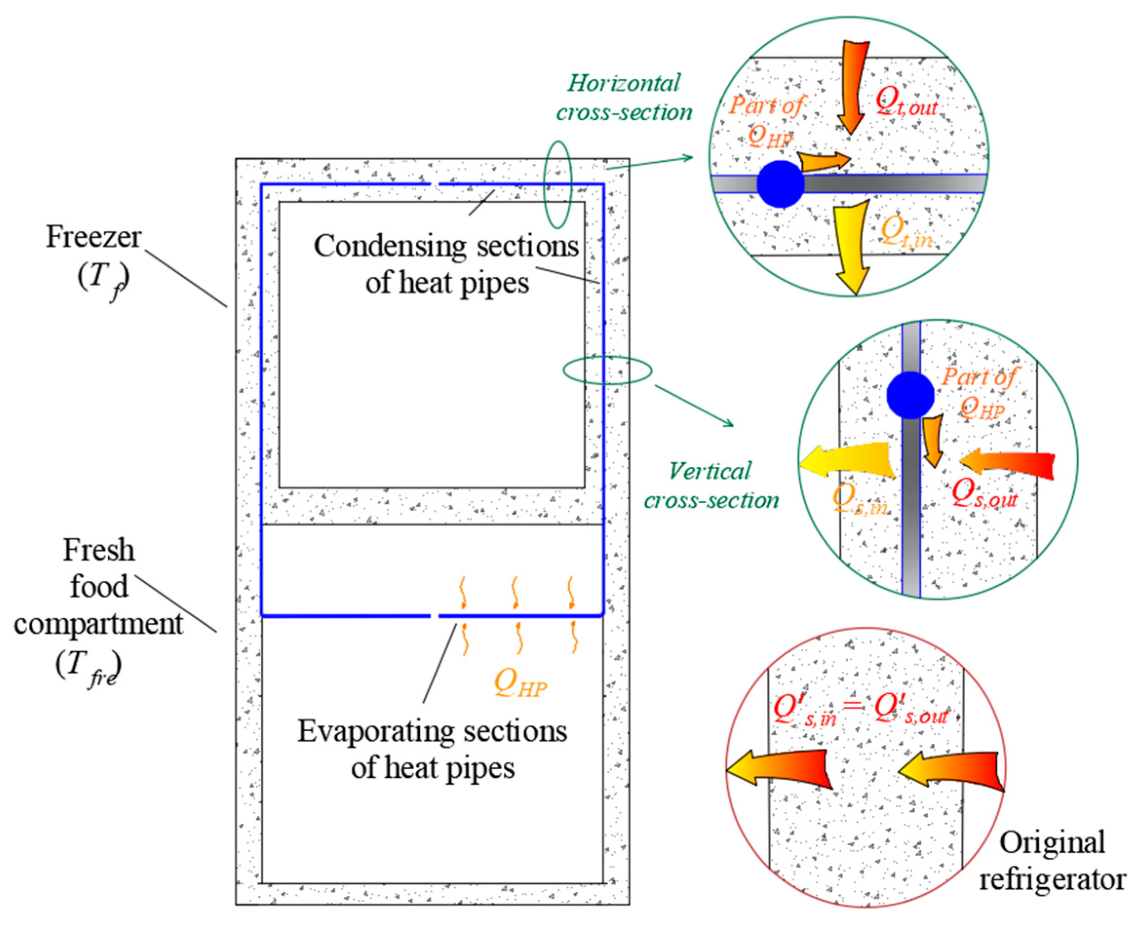
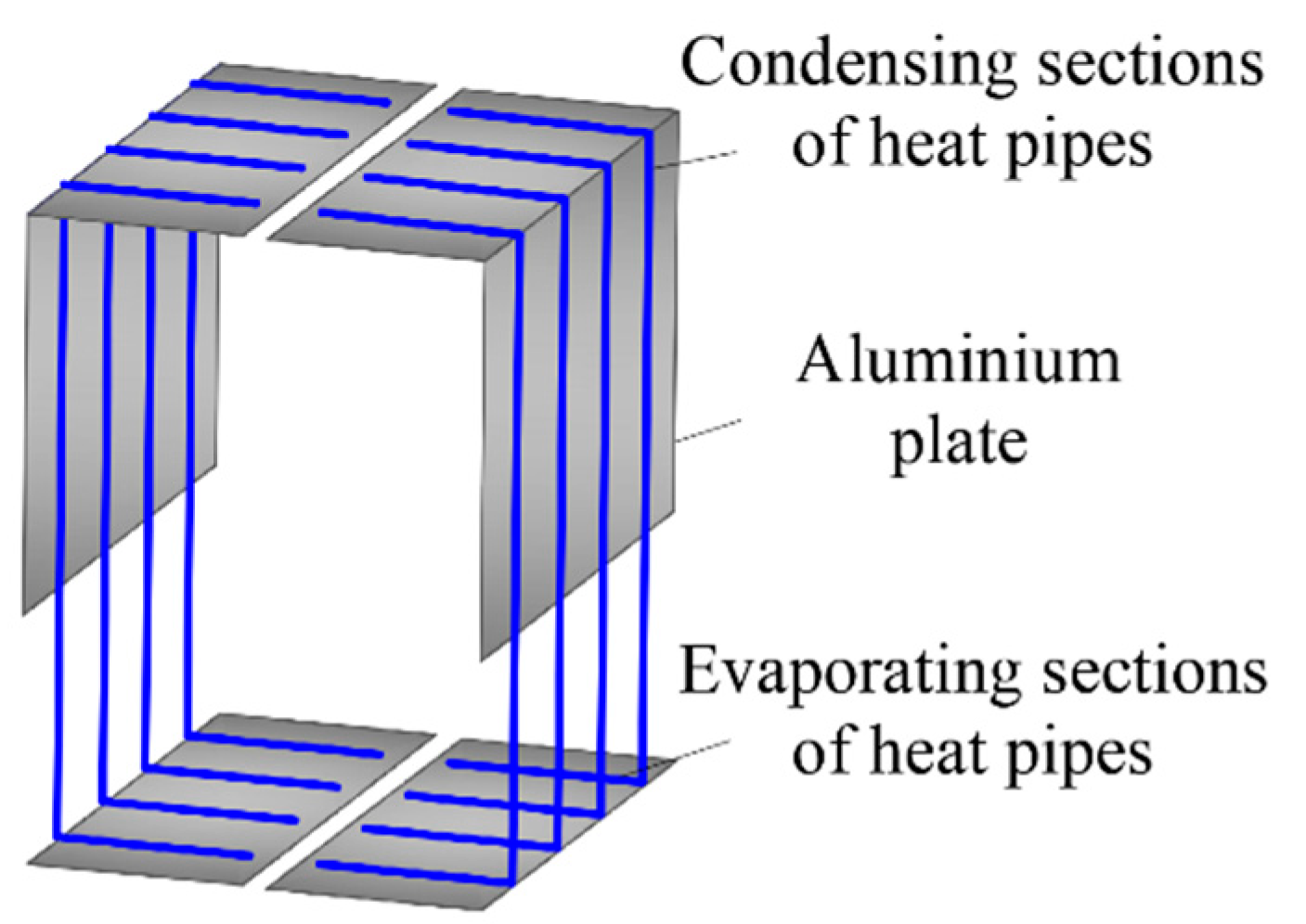
2. Operating Principle

The improved refrigerator is designed based on a Midea refrigerator numbered BCD-111, as shown in Figure 1. Two symmetrical heat pipes are installed into the refrigerator for reusing the wasted cold energy of the freezer. More specifically, only topside and side freezer walls are changed, and eight aluminum heat pipes are used to transport part of their cold loss to the fresh food compartment, as is depicted in Figure 2. Aluminum plates are adopted to enhance the heat transfer at evaporating and condensing sections. The diameter of the heat pipe and the thickness of aluminum plates are preliminarily designed as 6 mm. The evaporating sections of the heat pipes are designed to offer a support plate for the fresh food compartment.
The refrigerator is improved by wasted cold energy recovery at the freezer. As is compared in Figure 1, the modified walls of the improved freezer have a shunted heat transfer process. As one part of heat comes from the fresh food compartment, the heat leakage from the ambinet is reduced. The heat transfer processes of original and modified topside freezer walls are compared in Figure 3 as an example. The heat pipes change the temperature distribution of the freezer wall. In comparison of the installation position of heat pipes, the local temperature (T′HP) is raised to the temperature of the heat pipes (THP). Thus, the external heat flux (Qout) decreases, whereas the internal heat flux (Qin) increases. The heat flux difference between them (QHP) is acquired from the fresh food compartment using heat pipe. It should be emphasized that the heat transfer enhancement between the fresh food compartment and freezer (which could also be easily done by reducing its internal thermal isolation) is just a side effect, and the main purpose of adding heat pipes is to decrease the overall heat leakage of the improved refrigerator.

3. Measured Conditions of Midea BCD-111 Refrigerator

For performance comparison between the improved and the original refrigerators, the specific geometric parameters of Midea BCD-111 household refrigerator are measured. The length, the width, and the height of the freezer are 325 mm, 330 mm, and 300 mm, respectively, while the corresponding wall thicknesses are 80 mm, 70 mm, and 50 mm, respectively. The wall thickness between the freezer and the fresh food compartment is 50 mm. The temperature boundary conditions are also tested at different operating states of the refrigerator, as shown in Table 1. The ambient temperature and the average air temperatures in the freezer (Tf) and the fresh food compartment (Tfre) are measured according to the National Standard GB/T 8059-2016. Since the temperatures at the outside surface of side walls of the BCD-111 refrigerator are related to its condensing temperature, the outside surface temperature of side freezer wall (Ts,out) is also measured. Detailed temperature measurement methods can be found in reference [19].

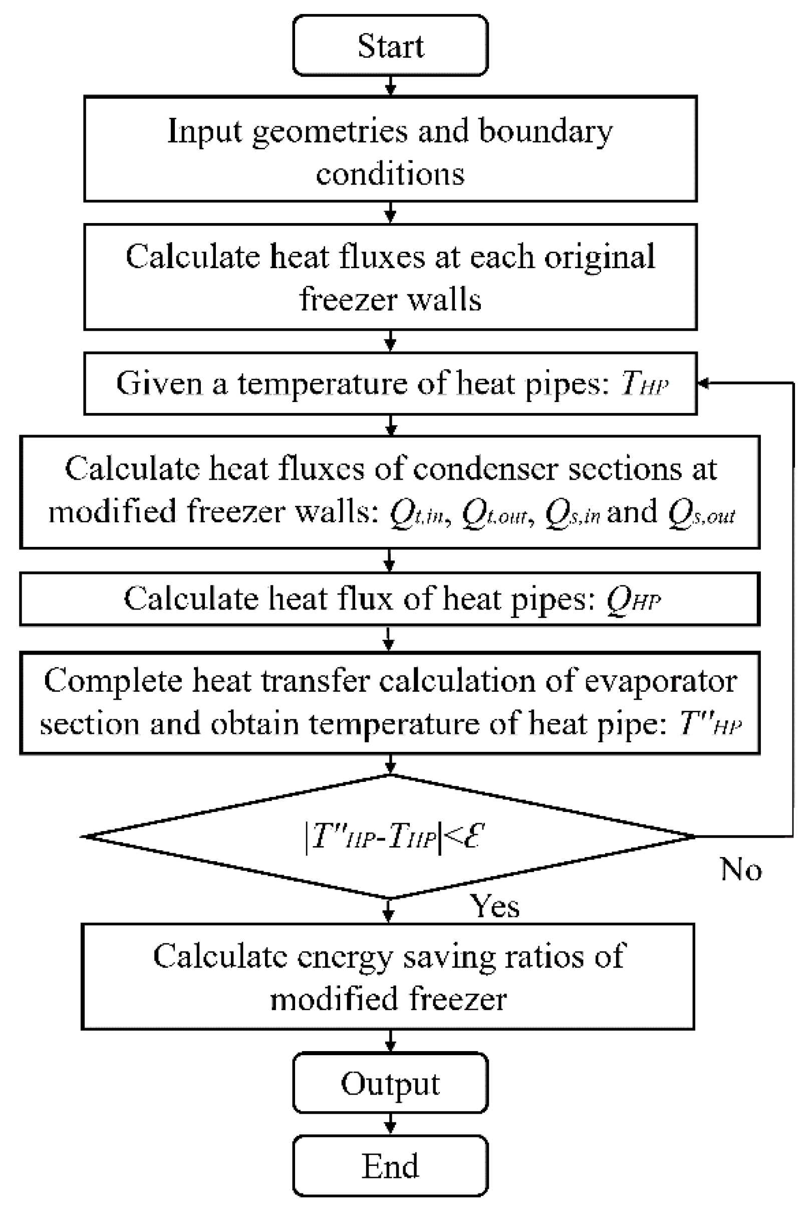
4. Mathematical Model

The simplified mathematical model is built for the original and the modified freezer of the BCD-111 refrigerator. The following hypotheses are adopted.
-
The temperature fluctuation of air is neglected.
-
The walls of refrigerator have the same heat conductive coefficient.
-
Rectangular straight fin efficiency is adopted for aluminum plates [20].
-
The heat transfer is steady-state and 1D.
-
The temperatures at evaporating and condensing sections of heat pipes are considered uniform (THP = Tcon = Teva) since the internal two-phase thermal resistance is far less than the external convective thermal resistance.
-
The external surface temperature of side freezer walls is given as a boundary condition due to the influence of condenser of the BCD-111 refrigerator.
The measured boundary conditions are utilized in following methods:
  • Boundary condition 1: the surrounding air temperatures are given for the original freezer walls (or the evaporating sections of heat pipes in fresh food compartment);
  • Boundary condition 2: the average outside wall temperatures are given for the improved freezer walls.
Based on the above hypotheses and boundary conditions, the thermal analyses of the original and improved refrigerator are conducted using iterative computations.
The heat fluxes at half of the topside freezer wall of the improved refrigerator are calculated based on the boundary condition 1, in which the heat conversion coefficient is calculated through self iteration:
Q t , o u t = T a m b T H P 1 α t , o u t + ( δ X t , i n ) λ A t
Q t , i n = T H P T f 1 α t , i n + X t , i n λ A t
where Qt,out and Qt,in are outside and inside heat fluxes, respectively; Tamb, THP, and Tf are ambient temperature, heat pipe temperature, and freezer temperature, respectively; αt,out and αt,in are the convective heat transfer coefficients of ambient and inside air, respectively; δ is the wall thickness; Xt is the ratio of wall thickness inside of heat pipes to the whole topside wall thickness; and At is the topside heat transfer area.
The heat fluxes at left or right freezer walls of the improved refrigerator are calculated based on the boundary condition 2.
Q s , o u t = T s , o u t T H P ( δ X s , i n ) λ A s
Q s , i n = T H P T f 1 α s , i n + X s , i n λ A s
where Qs,out and Qs,in are outside and inside heat fluxes, respectively; Ts,out is the outside surface temperature of side freezer wall; αt,out and αt,in are the convective heat transfer coefficients of ambient and inside air, respectively; Xs is the ratio of wall thickness inside of heat pipes to the whole side wall thickness; and As is the side heat transfer area.
For the condensing section of heat pipes, the heat is released to the topside and the side freezer walls.
Q H P = ( Q s , i n + Q t , i n ) ( Q s , o u t + Q t , o u t )
where QHP is the heat flux of heat pipes; Qs,in and Qs,out are inside and outside heat flux at each side freezer wall, respectively; and Qt,in and Qt,out are inside and outside heat flux at half of the topside freezer wall, respectively.
Meanwhile, the heat gain at the evaporating sections of heat pipes is as follows:
Q H P = ( α e v a , u + α e v a , l ) ( T f r e T H P ) A e v a
where αeva,u and αeva,l are the convective heat transfer coefficients of upper and lower surfaces of the evaporating sections of heat pipes, respectively; Tfre is the fresh food compartment temperature; and Aeva is the area of the evaporating sections of heat pipes.
Based on the above calculations, the heat transfer state of the freezer of the improved refrigerator can be acquired by iterating THP. Besides, the heat fluxes at the front and the back freezer walls of the improved refrigerator or the freezer walls of the original refrigerator are easily calculated based on the boundary conditions 1 or 2, and thus the energy saving ratios of the freezer of the improved refrigerator are as follows.
η r e , s = ( 1 C s C s ) × 100 %
η r e , t = ( 1 C t C t ) × 100 %
η r e = ( 1 C C ) × 100 %
where ηre,s, ηre,t, and ηre are the energy saving ratios of the side wall, the topside wall, and the whole freezer of the improved refrigerator, respectively; C, Cs, and Ct are freezer cold loss and cold losses at the side and the topside freezer walls for the improved refrigerator, respectively (Cs = 2 × Qs,out and Ct = 2 × Qt,out); and C’s, C’t, and C’ are the cold losses of the side wall, the topside wall, and the whole freezer of the original refrigerator, respectively.
The detailed calculation procedure is depicted in Figure 4.

5. Results and Discussion

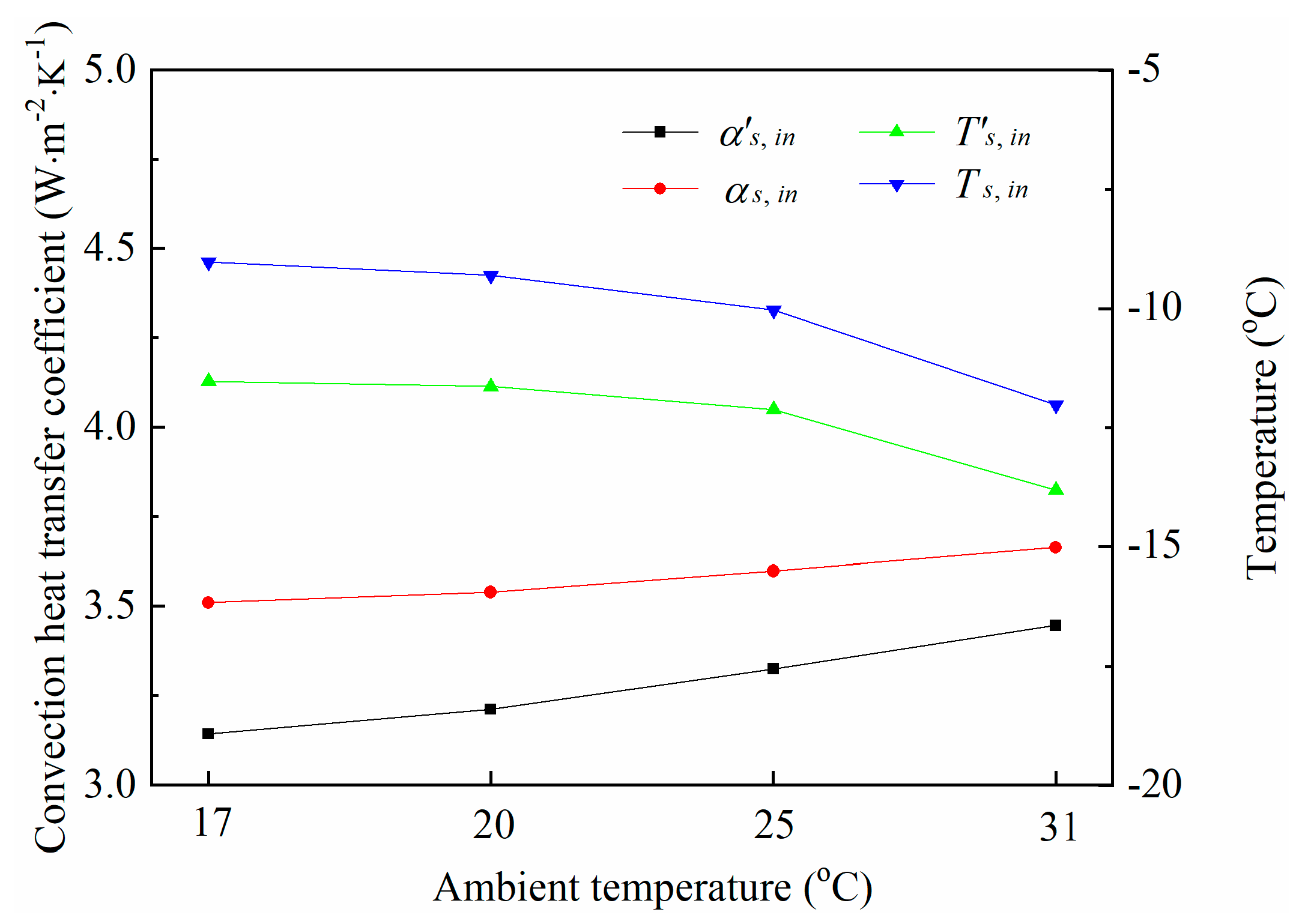
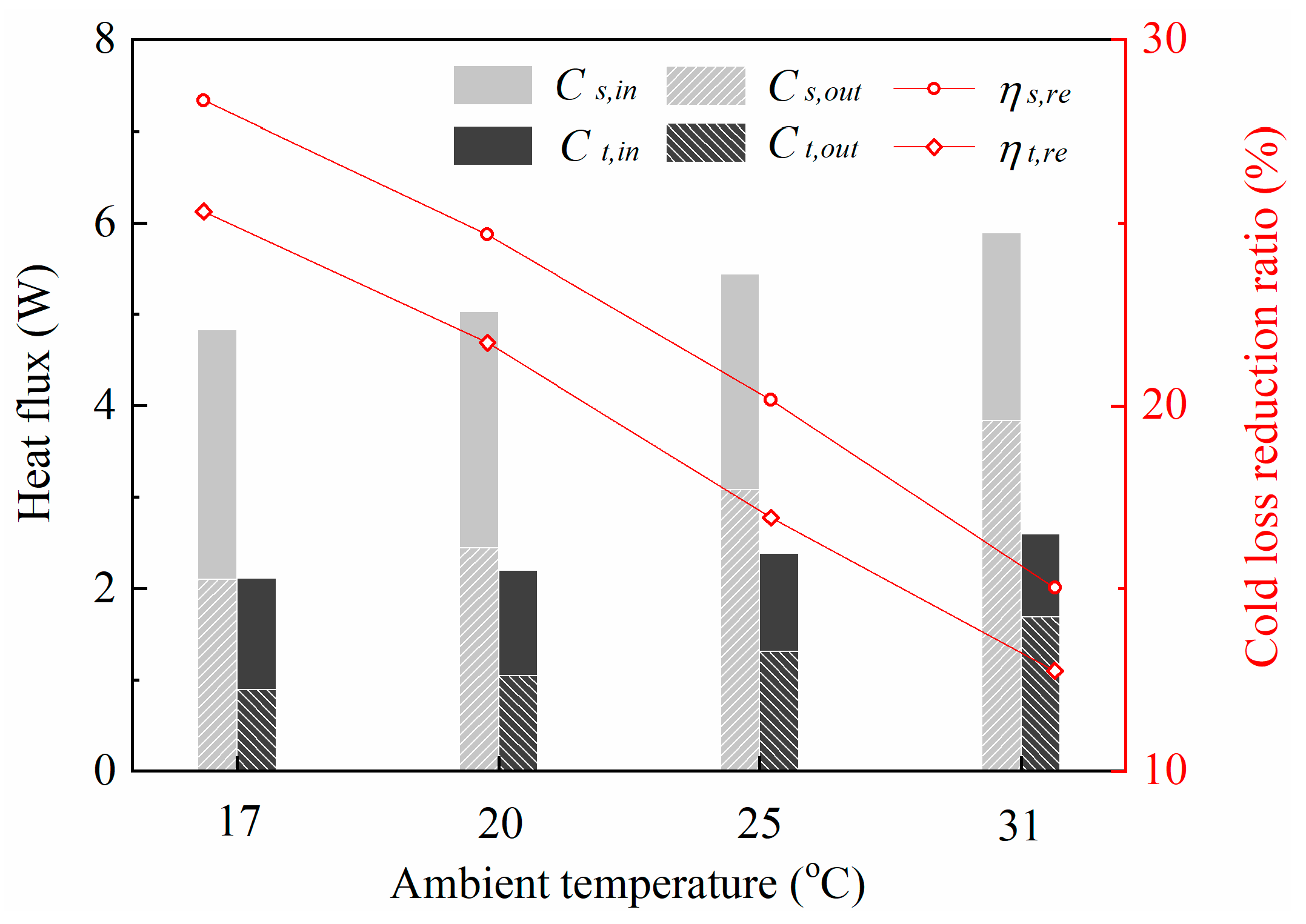
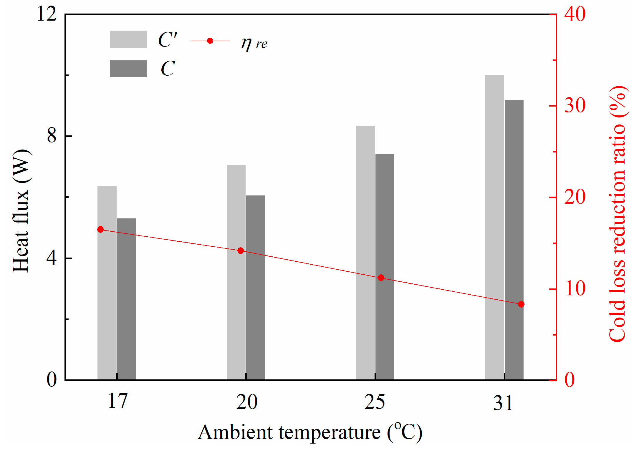
5.1. Performances at Different Ambient Temperatures

Ambient temperature seriously affects the operating state of household refrigerators. When the temperature gear of the BCD-111 refrigerator is fixed to C, the temperature boundary conditions at ambient temperatures of 17.0 °C to 31.0 °C are adopted for analyzing the performances of the improved refrigerator. The common ratio of wall thickness inside of heat pipes to the whole wall thickness, Xin (namely Xin = Xt,in = Xs,in), is preliminarily set to 16%. The heat transfer area of the evaporating section of heat pipes (Aeva) is given as its maximum value of 0.146 m2. In the side and the topside freezer walls of the improved refrigerator, considerable heat is transported to the freezer by heat pipes, which changes the thermal characteristics of the freezer walls. Since the outside surface temperature of side freezer walls is greatly affected by the ambient temperature, the side freezer walls of the original and the modified refrigerators are firstly compared in Figure 5. The convective heat transfer coefficients inside of the side freezer wall (α’s,in and αs,in) both increase steadily with ambient temperature, but their difference gradually drops from 0.37 W·m−2·K−1 to 0.22 W·m−2·K−1 (the radiative heat flux is relatively low and thus is neglected to simplify the calculation). Correspondingly, the outside surface temperature of the original side freezer wall decreases from −11.5 °C to −13.8 °C, while that of the modified one reduces from −9.0 °C to −12.0 °C, and the gap between them gradually narrows from 2.5 °C to 1.8 °C. The above phenomena show that inside heat transfer of the modified side freezer wall is enhanced due to the existence of heat pipes, and the influence of heat pipes steadily decreases as the heat leakage increases with the ambient temperature.
This section is not mandatory, but may be added if there are patents resulting from the work reported in this manuscript.
Figure 6 further compares the cold loss recovery behaviors of the side and the topside freezer walls. When the ambient temperature is 20 °C, the cold loss at the inside surfaces of the two side modified freezer walls (Cs,in) is 5.0 W, and the corresponding outside one (Cs,out) is reduced to 2.4 W. Meanwhile, the cold loss at the inside surface of the topside modified freezer wall (Ct,in) is 2.2 W, and the corresponding outside one (Ct,out) drops to 1.0 W. In comparison to the original freezer walls, about 24.7% of the cold loss of side freezer walls and 21.7% of the cold loss of topside freezer wall are recovered by the heat pipes. With a raising ambient temperature, Cs,out increases from 2.1 W to 3.8 W, and Ct,out enlarges from 0.9 W to 1.7 W. The cold loss reduction ratios of side and topside freezer walls (ηs,re and ηt,re, respectively) significantly drops from 28.3% to 15.0% and from 25.3% to 12.8%, respectively. The cold loss recovery behavior of modified side freezer wall remains better than the topside one, and their cold loss recovery capabilities are both considerably restricted by a high ambient temperature.
The overall cold loss recovery performances of the modified freezer at various ambient temperatures are presented in Figure 7. The cold loss of original freezer increases from 6.4 W to 10.0 W, while that of the modified freezer raises from 5.3 W to 9.2 W with a raising ambient temperature. Correspondingly, the cold loss reduction ratio of the freezer (ηre) decreases from 16.5% to 8.3%. The results indicate that more cold loss could be recycled by the heat pipes when the refrigerator runs with a lower ambient temperature. In general, the energy saving of the improved refrigerator is reliable when ambient condition varies within a typical range.

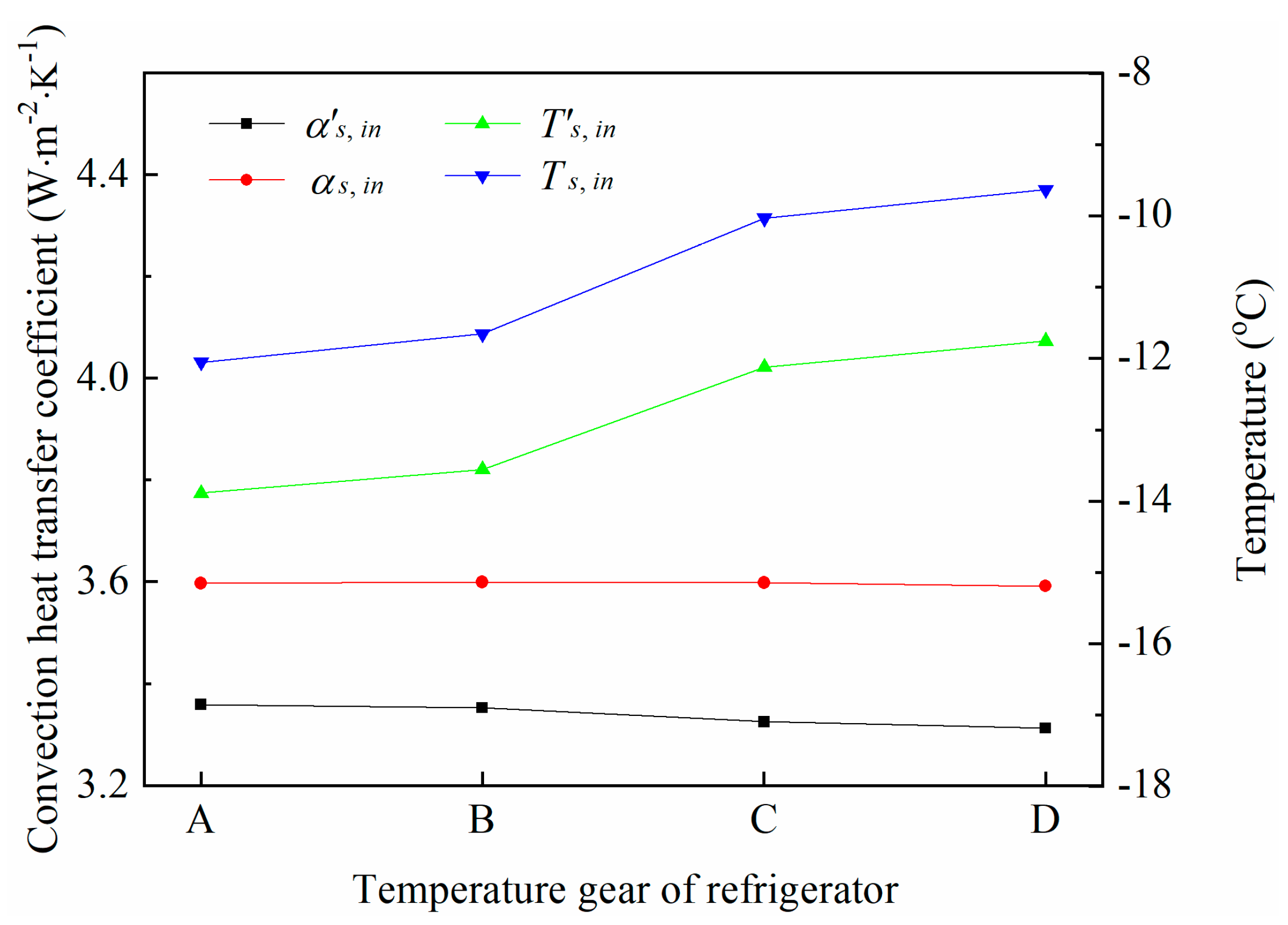
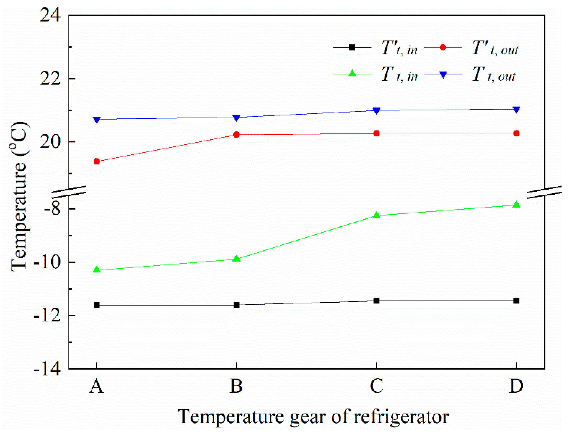
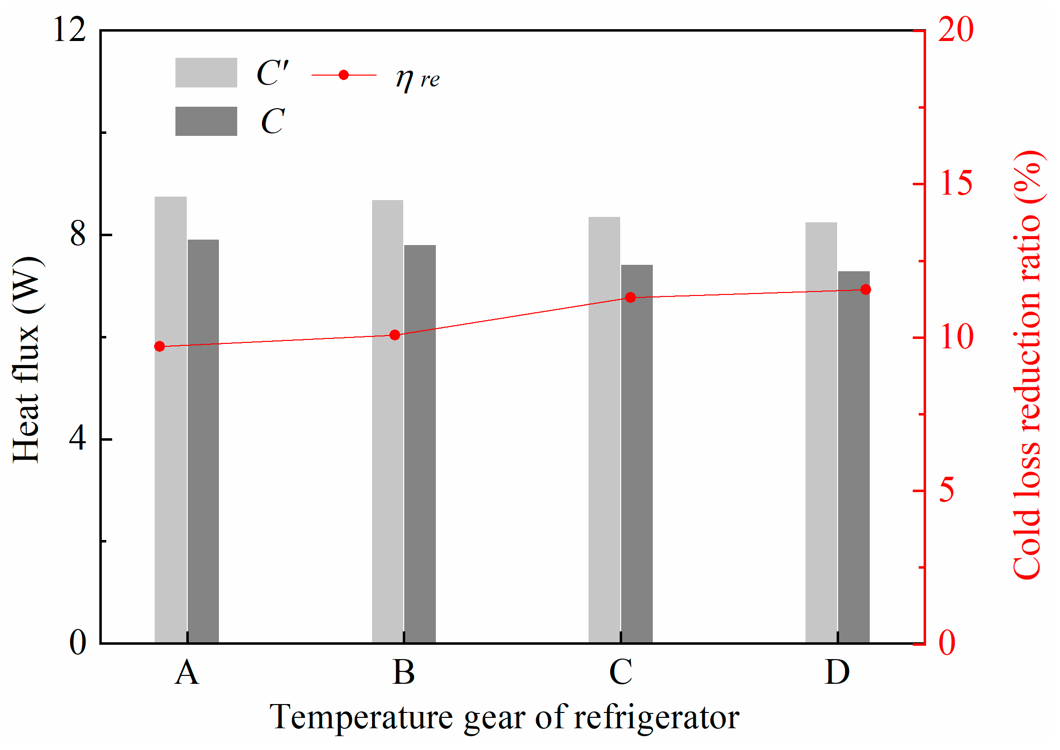
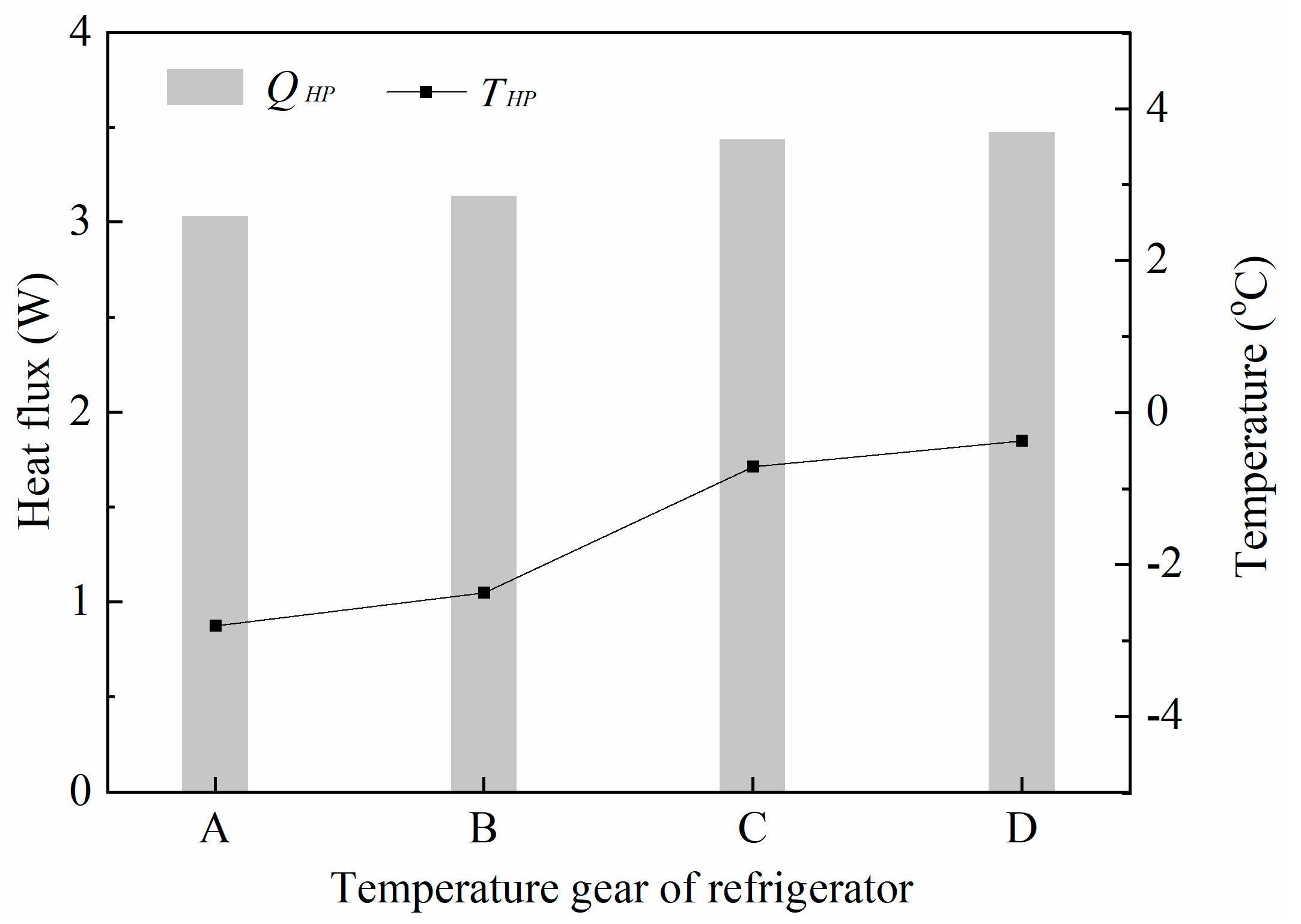
5.2. Performances at Different Temperature Gears

When the ambient temperatures, Aeva and Xin, are fixed to 25.0 °C, 0.146 m2, and 16%, respectively, and the temperature gears are given as A~D, the measured boundary conditions are utilized to further compare the performances of original and improved refrigerators. The representative heat transfer parameters of original and improved side freezer walls are shown in Figure 8. As the temperature gear is adjusted from A to D, the inside convective heat transfer coefficient for the original side wall (α’s,in) remains close to 3.34 W·m−2·K−1, whereas that for the modified one (α′s,in) remains at about 3.59 W·m−2·K−1. The inside surface temperature for the modified side wall (Ts,in) raises from −12.1 °C to −9.6 °C; and the inside surface temperature for the original side wall (T’s,in) raises from −13.9 °C to −11.8 °C. When the temperature gear changes from A to D, Ts,in remains higher than T’s,in, and their difference slightly enlarges from 1.8 °C to 2.1 °C. The enhancement on the inside heat transfer of the modified side freezer wall intensifies as the inside temperatures of the refrigerator raise.
The topside freezer wall of the improved refrigerator is with boundary condition 1, and thus the bilateral heat transfer characteristics are affected by the heat pipe. Figure 9 shows the surface temperature comparison between the original and the modified topside freezer walls under different temperature gears. Take temperature gear B for example, the outside surface temperature increases from 20.2 °C to 20.8 °C after adding the heat pipe, and the inside surface temperature correspondingly increases from −11.6 °C to −9.9 °C. The existence of the heat pipes changes the temperature distribution in the topside freezer wall and reduces the temperature gap between its outside surface and ambient air. The phenomenon indicates that a considerable heat energy is transported from the fresh food compartment and flow into the freezer along with the outside heat leakage. Besides, the inside surface temperature for the modified topside freezer wall (Tt,in) raises from −10.3 °C to −7.9 °C, and the outside surface temperature for the original topside freezer wall (T’t,out) slightly increases from 19.4 °C to 20.3 °C. The inside surface temperature for the original topside freezer wall (T’t,in) and the outside surface temperature for the modified topside freezer wall (Tt,out) remain close to −11.5 °C and 20.8 °C, respectively. Results confirm that the influence of heat pipes intensifies as the inside temperatures of the refrigerator raise.
The heat transfer behaviors of the heat pipes are further studied to support the above analyses. As shown in Figure 10, the temperature of the heat pipes (THP) raises from −2.8 °C to −0.4 °C as the temperature gear is varied from A to D, and the difference between the air temperature at the fresh food compartment and THP enlarges from 4.9 °C to 5.4 °C. Correspondingly, the heat transfer capability of heat pipes enhances and its heat flux (QHP) increases from 3.0 W to 3.5 W. Heat pipes provide a cold loss recovery function for the freezer, and the heat shunt amount is closely affected by the temperature gear of the refrigerator. Since the temperature of evaporating sections of heat pipes in the fresh food compartment is close to 0 °C and is much higher than the temperature of the original evaporator of the refrigerator, the problem of frosting in the evaporating sections of the heat pipes is less serious.
Figure 11 compares the cold losses of the original and the modified freezer to overall evaluate the cold loss recovery behaviors of the improved refrigerator. Taking temperature gear B as an example, the cold loss of the freezer drops 0.9 W after adding heat pipes, which means 10.1% of cold loss can be recovered by the heat pipe. When the temperature gear varies from A to D, the cold losses of the original and the modified freezers both decrease 0.6 W, and the cold loss reduction ratio (ηre) correspondingly increases from 9.7% to 11.6%. On the whole, the improved refrigerator can effectively reduce the cold loss of the freezer even if the temperature gear of the refrigerator changes. The energy saving performance slightly enhances as the cold loss amount decreases with increasing inside temperatures of the refrigerator.

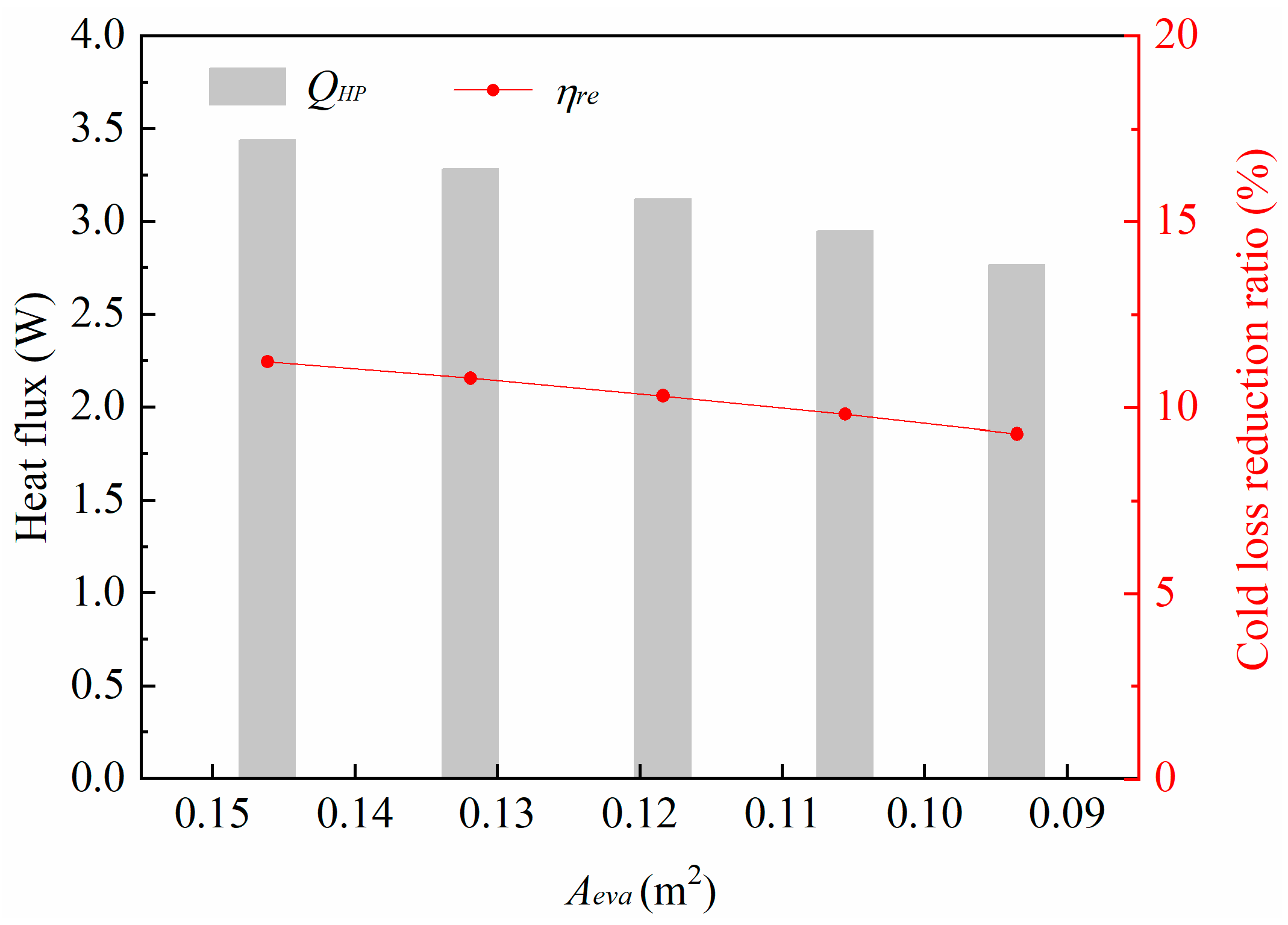
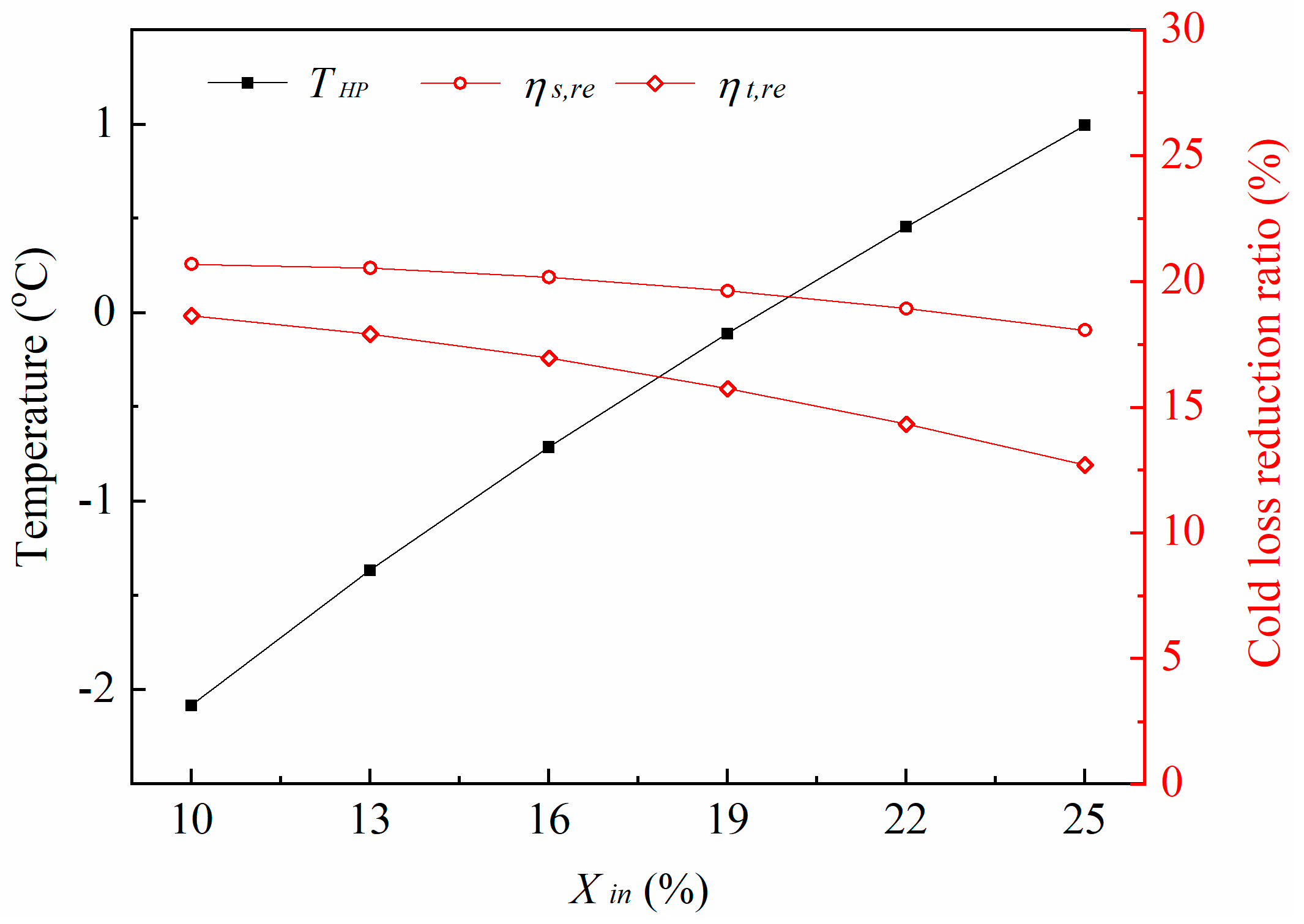
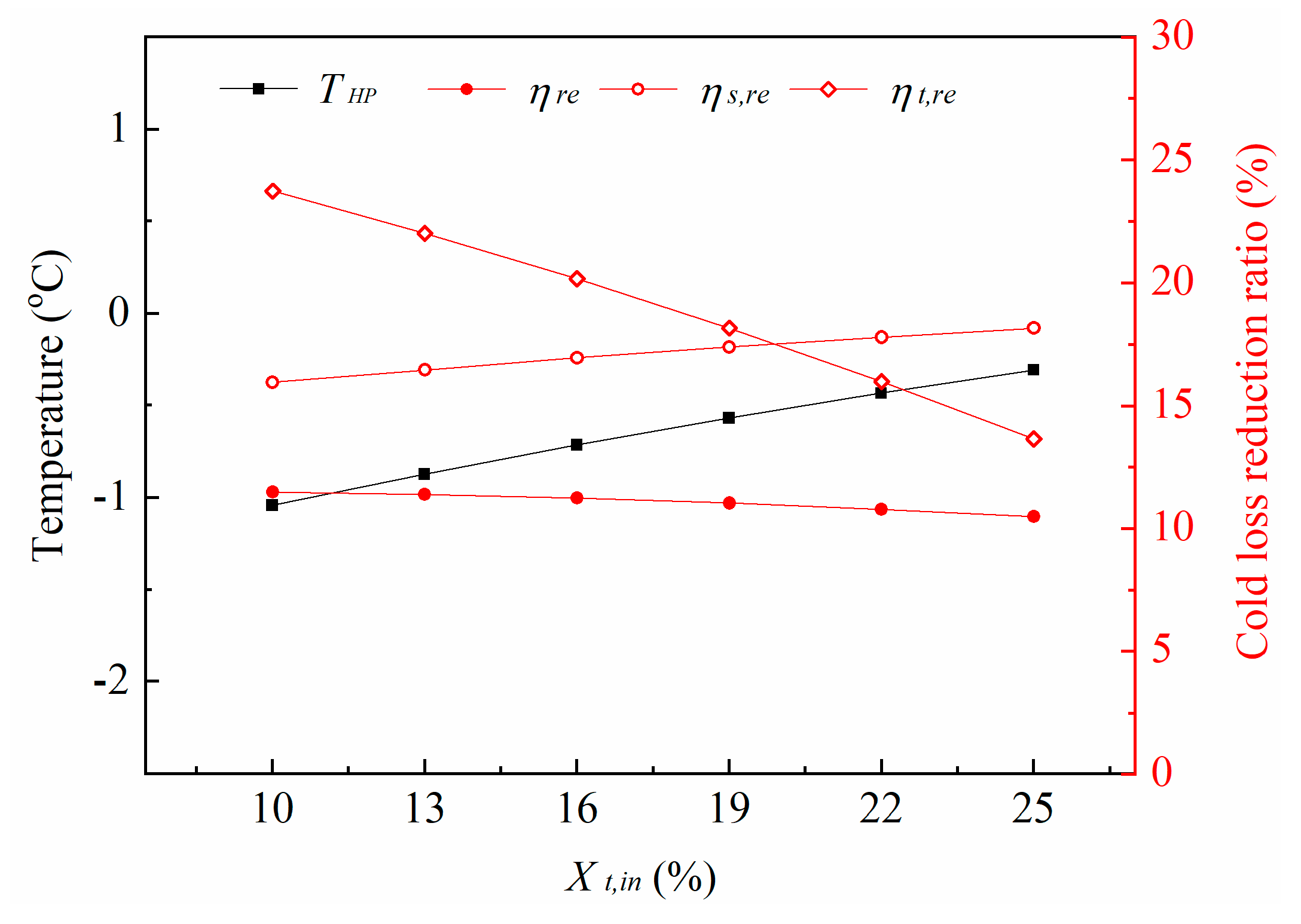
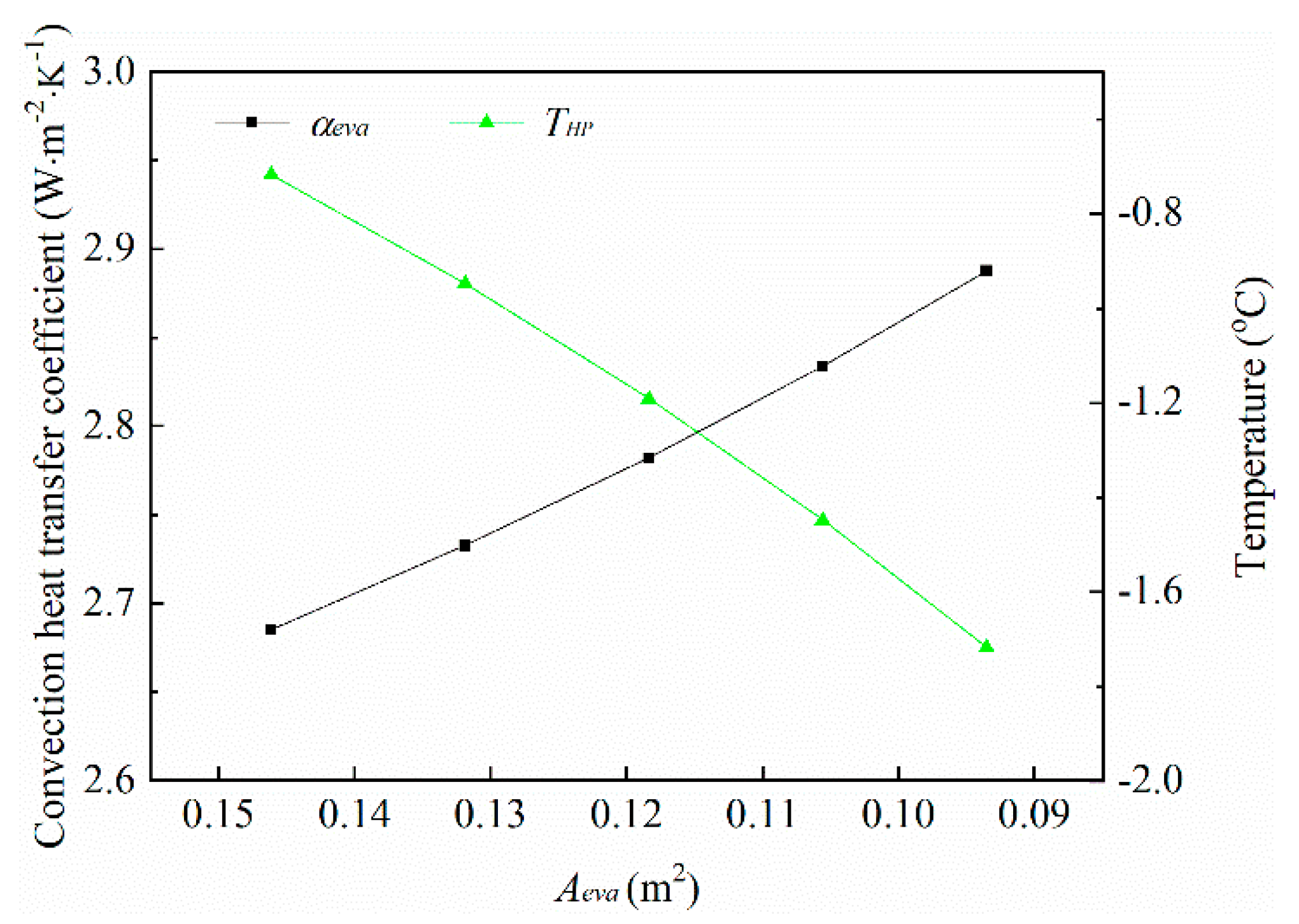
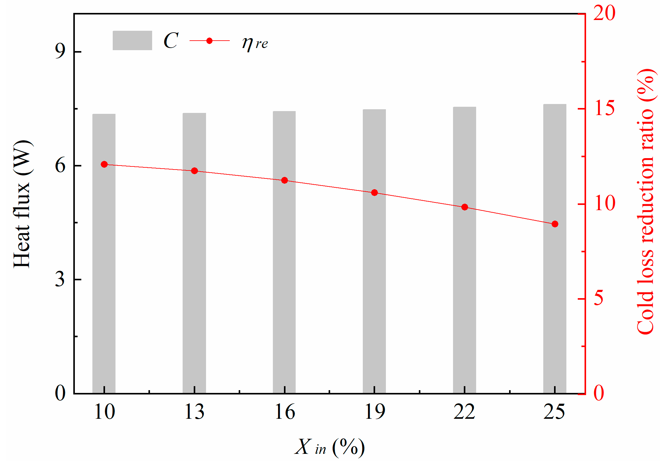
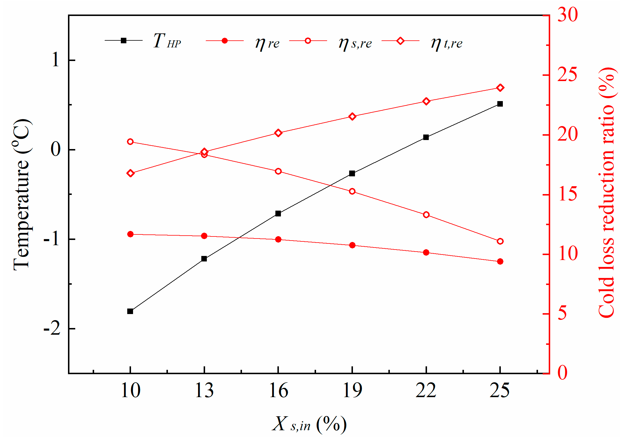
5.3. Performances at Different Heat Pipe Design

In the above calculations, the heat transfer area of the evaporating sections of heat pipes is fixed, and its specific location in the side and the topside freezer wall is also set to the same. In this section, the heat transfer area of the evaporating sections of heat pipes along with the distances between the condensing sections of heat pipes and the inner walls are changed to further evaluate the influences of the heat pipe design. The behaviors of the improved refrigerator are analyzed for ambient temperature of 25 °C and temperature gear C.
The heat transfer area of the evaporating sections of heat pipes (Aeva) is firstly reduced from 0.146 m2 to 0.094 m2, while the ratio of length to width remains constant. The variations of the average convective heat transfer coefficients of the upper and the lower surfaces of the evaporating sections of heat pipes (αeva) and the temperature of the heat pipes (THP) are shown in Figure 12. As the heat transfer area reduces 9.8%, 19.0%, 27.8%, and 36.0%, αeva raises gradually from 2.68 W·m−2·K−1 to 2.83 W·m−2·K−1, 2.78 W·m−2·K−1, 2.73 W·m−2·K−1, and 2.89 W·m−2·K−1, respectively. Correspondingly, THP decreases from −0.7 °C to −0.9 °C, −1.2 °C, −1.4 °C, and −1.7 °C, respectively. The convective heat transfer capability of the evaporating sections of heat pipes per unit area gradually increases as the temperature gap between the heat pipes and the fresh food compartment enlarges. The heat transfer area of the evaporating sections of heat pipes could considerably affect the internal heat transfer of the improved refrigerator.
The impact of heat transfer area reduction of the evaporating sections of heat pipes on the overall behaviors of the improved refrigerator are further shown in Figure 13. When Aeva reduces from 0.146 m2 to 0.094 m2, the heat flux of the heat pipes (QHP) drops from 3.4 W to 2.8 W, and the heat flux decreasing ratio is about 80.4%. Correspondingly, the cold loss reduction ratio (ηre) decreases from 11.2% to 9.3%, and its decreasing ratio is about 82.8%. Results indicate that reduction on the heat transfer area of heat pipes in the fresh food compartment weakens the heat transfer of the heat pipes and thus causes a performance degradation of the improved refrigerator. However, the simulation also proves that a slight sacrifice of heat transfer area for the convenience of design and manufacture of the improved refrigerator is feasible.
Thereafter, given the maximum Aeva of 0.146 m2, the common ratio of wall thickness inside of heat pipes to the whole wall thickness (Xin) is changed from 10% to 25%, and the temperatures of heat pipes and cold reduction ratios of side and topside freezer walls are shown in Figure 14. The temperature of heat pipes (THP) raises from −2.1 °C to 1.0 °C with increasing Xin. Correspondingly, the cold loss reduction ratio of the side freezer wall (ηs,re) and that of the topside freezer wall (ηt,re) gradually decrease from 20.7% to 18.1% and from 18.6% to 12.7%, respectively. Given the same location of the heat pipe, the cold loss reduction capability of the modified side freezer wall remains higher than that of the topside one, but the gap between ηs,re and ηt,re significantly enlarges from 2.1% to 5.4%. The temperature of heat pipes is closely related with its installation position in the freezer walls, and the cold loss reduction behavior of the side freezer walls is relatively more stable, even if the location of heat pipes changes. Correspondingly, Figure 15 shows the overall behaviors of the modified freezer with increasing Xin. Cold loss of the modified freezer (C) slightly drops from 7.3 W to 7.6 W, and cold loss reduction ratio (ηre) decreases from 12.1% to 8.9% as Xin increases from 10% to 25%. The overall cold loss recovery amounts of heat pipes at various installation positions remain relatively stable. These results certify the reliability of the energy saving function of the improved refrigerator.
Furthermore, the locations of the condensing sections of heat pipes in the side and the topside freezer walls are individually varied, and the behaviors of the improved refrigerator are evaluated to reveal the energy saving difference at the side and the topside freezer walls. The ratio of wall thickness inside of heat pipes to the whole side wall thickness (Xs,in) is varied from 10% to 25%, while that for topside freezer wall (Xt,in) is fixed to 16%, and the calculated results are shown in Figure 16. THP raises from −1.8 °C to 0.5 °C, ηre decreases from 11.7% to 9.4%, and their variation ranges are smaller compared with the operating states with changing Xs,in and Xt,in together (shown in Figure 14 and Figure 15). In particular, ηs,re drops from 19.4% to 11.1% whereas ηt,re raises from 16.8% to 24.0%. The temperature distribution at the topside freezer wall is affected by the raising THP, and thus its cold loss drops, even if Xt,in is constant. For comparison, the behavior of the improved refrigerator is shown in Figure 17 as Xt,in is varied from 10% to 25% with a fixed Xs,in. Correspondingly, ηs,re increases from 16.0% to 18.2%, ηt,re reduces from 23.7% to 13.6%, THP slightly raises from −1.0 °C to −0.3 °C, and ηre decreases from 11.5% to 10.5%. The performance responses to the variation of Xt,in are much weaker than those of Xs,in, which indicates the location of condensing sections of heat pipes at the topside freezer wall plays a more important role. Generally, properly adjusting the location of condensing sections of heat pipes at each freezer can vary the cold loss recovery capability of the improved refrigerator, and the energy saving design is feasible as Xs,in and Xt,in are changed between 10% to 25%.

6. Conclusions

An improved household refrigerator with heat pipes was designed to reduce the energy consumption of residential buildings. A simplified mathematical model was built combining the structure parameters and measured temperature boundary conditions of the BCD-111 refrigerator. The energy-saving performance of this improved refrigerator was numerically investigated by changing the temperature gear of the refrigerator from A to D, raising the ambient temperature from 17 °C to 31 °C, and varying the specific design of the heat pipes. The cold loss reduction ratios of the modified freezer were 8.3–16.5%, 9.7–11.6%, 9.3–11.2% and 8.9–12.1%, respectively, as responses to changing ambient temperature, temperature gear, heat transfer area, and location of heat pipes. Since the additional aluminum heat pipes and plates in the improved refrigerator have a relatively low cost, long service life, and little maintenance requirement, reusing wasted cold energy of a freezer is a feasible improvement method for a traditional household refrigerator. The current problem may be that the manufacturing processes of the improved refrigerator are more complex, and further research is required to reduce its manufacturing difficulty.

Author Contributions

Conceptualization, J.C., M.H. and G.P.; Data curation, J.C.; Formal analysis, J.C., Q.W. and X.R.; Funding acquisition, G.P., J.C. and M.H.; Investigation, J.C., Q.W., M.H. and W.L.; Methodology, J.C.; Project administration, M.H. and G.P.; Resources, G.P.; Software, X.R.; Supervision, Y.S. and G.P.; Validation, Q.W.; Writing—original draft, J.C. All authors have read and agreed to the published version of the manuscript.

Funding

The study was sponsored by the National Key R&D Program of China (2018YFB1900602), the Anhui Provincial Natural Science Foundation (2008085QE234), the China Postdoctoral Science Foundation (2019M652209), the Fundamental Research Funds for the Central Universities (WK2090130024), and the National Natural Science Foundation of China (NSFC 51906241, 51761145109, and 51776193).

Conflicts of Interest

The authors declare no conflict of interest.

Nomenclature

Aheat transfer area [m2]
ambambient air
Ccold loss [W]
HPheat pipes
Qheat flux [W]
Rthermal resistance [K·W−1]
Ttemperature [°C]
Xinratio of wall thickness inside of heat pipes to whole wall thickness [%]
Greek letters
αconvective heat transfer coefficient [W·m−2·K−1]
δwall thickness [m]
εiteration error
λheat conductivity coefficient [W·m−1·K−1]
ηratio [%]
Superscripts
original refrigerator
iterative value
Subscripts
1boundary condition 1
2boundary condition 2
concondensing section
HPheat pipe
dheat conduction
evaevaporating section
ffreezer
frefresh food compartment
ininside
ouroutside
rerecovery
sside freezer wall
ttopside freezer wall
vconvective heat transfer
wfreezer wall

References

  1. Zhao, H.X.; Magoules, F. A review on the prediction of building energy consumption. Renew. Sustain. Energy Rev. 2012, 16, 3586–3592. [Google Scholar] [CrossRef]
  2. Jones, R.V.; Fuertes, A.; Lomas, K.J. The socio-economic, dwelling and appliance related factors affecting electricity consumption in domestic buildings. Renew. Sustain. Energy Rev. 2015, 43, 901–917. [Google Scholar] [CrossRef] [Green Version]
  3. Pirvaram, A.; Sadrameli, S.M.; Abdolmaleki, L. Energy management of a household refrigerator using eutectic environmental friendly PCMs in a cascaded condition. Energy 2019, 181, 321–330. [Google Scholar] [CrossRef]
  4. Jomde, A.; Bhojwani, V.; Deshnnukh, S. Challenges in implementation of a moving coil linear compressor in a household refrigerator. Int. J. Ambient Energy 2019, 1–4. [Google Scholar] [CrossRef]
  5. Tosun, M.; Dogan, B.; Ozturk, M.M.; Erbay, L.B. Integration of a mini-channel condenser into a household refrigerator with regard to accurate capillary tube length and refrigerant amount. Int. J. Refrig. 2019, 98, 428–435. [Google Scholar] [CrossRef]
  6. Alhamid, M.; Nasruddin, N.; Susanto, E.; Vickary, T.; Budiyanto, M.A.J.E. Refrigeration Cycle Exergy-Based Analysis of Hydrocarbon (R600a) Refrigerant for Optimization of Household Refrigerator. Evergreen 2019, 6, 71–77. [Google Scholar] [CrossRef]
  7. Maiorino, A.; Del Duca, M.G.; Mota-Babiloni, A.; Greco, A.; Aprea, C. The thermal performances of a refrigerator incorporating a phase change material. Int. J. Refrig. 2019, 100, 255–264. [Google Scholar] [CrossRef]
  8. Kojima, K.; Shinagawa, E.; Uematsu, I.; Hayamizu, N.; Ooshiro, K. Vacuum Insulation Panel, Core Material, and Refrigerator. U.S. Patent Application 15/556,920, 22 August 2019. [Google Scholar]
  9. Kim, H.C.; Keoleian, G.A.; Horie, Y.A. Optimal household refrigerator replacement policy for life cycle energy, greenhouse gas emissions, and cost. Energy Policy 2006, 34, 2310–2323. [Google Scholar] [CrossRef]
  10. Cheng, W.L.; Ding, M.; Yuan, X.D.; Han, B.C. Analysis of energy saving performance for household refrigerator with thermal storage of condenser and evaporator. Energy Convers. Manag. 2017, 132, 180–188. [Google Scholar] [CrossRef]
  11. Afonso, C.F. Household refrigerators: Forced air ventilation in the compressor and its positive environmental impact. Int. J. Refrig. 2013, 36, 904–912. [Google Scholar] [CrossRef]
  12. Liu, Y.C.; Chen, K.; Xin, T.L.; Cao, L.H.; Chen, S.M.; Chen, L.X.; Ma, W.W. Experimental study on household refrigerator with diffuser pipe. Appl. Therm. Eng. 2011, 31, 1468–1473. [Google Scholar] [CrossRef]
  13. Cao, J.Y.; Li, J.; Zhao, P.H.; Jiao, D.S.; Li, P.C.; Hu, M.K.; Pei, G. Performance evaluation of controllable separate heat pipes. Appl. Therm. Eng. 2016, 100, 518–527. [Google Scholar] [CrossRef] [Green Version]
  14. Cao, J.Y.; Pei, G.; Chen, C.X.; Jiao, D.S.; Jing, L. Preliminary study on variable conductance loop thermosyphons. Energy Convers. Manag. 2017, 147, 66–74. [Google Scholar] [CrossRef]
  15. Soylemez, E.; Alpman, E.; Onat, A. Experimental analysis of hybrid household refrigerators including thermoelectric and vapour compression cooling systems. Int. J. Refrig. 2018, 95, 93–107. [Google Scholar] [CrossRef]
  16. Fatouh, M.; Abou-Ziyan, H.J.A.T.E. Energy and exergy analysis of a household refrigerator using a ternary hydrocarbon mixture in tropical environment–Effects of refrigerant charge and capillary length. Appl. Therm. Eng. 2018, 145, 14–26. [Google Scholar] [CrossRef]
  17. Moayednia, N.; Ehsani, M.R.; Emamdjomeh, Z.; Asadi, M.M.; Mizani, M.; Mazaheri, A.F.J.A.J.o.B.; Sciences, A. The effect of sodium alginate concentrations on viability of immobilized Lactobacillus acidophilus in fruit alginate coating during refrigerator storage. Aust. J. Basic Appl. Sci. 2009, 3, 3213–3226. [Google Scholar]
  18. Cao, J.Y.; Chen, C.X.; Gao, G.T.; Yang, H.L.; Su, Y.H.; Bottarelli, M.; Cannistraro, M.; Pei, G. Preliminary evaluation of the energy-saving behavior of a novel household refrigerator. J. Renew. Sustain. Energy 2019, 11, 015102. [Google Scholar] [CrossRef]
  19. Cao, J.Y.; Chen, C.X.; Hu, M.K.; Wang, Q.L.; Cannistraro, M.; Leung, M.K.H.; Pei, G. Numerical analysis of a novel household refrigerator with controllable loop thermosyphons. Int. J. Refrig. 2019, 104, 134–143. [Google Scholar] [CrossRef]
  20. Bergman, T.L.; Incropera, F.P.; DeWitt, D.P.; Lavine, A.S. Fundamentals of Heat and Mass Transfer; John Wiley & Sons: Hoboken, NJ, USA, 2011. [Google Scholar]
Figure 1. Section views of the improved refrigerator.
Applsci 10 04246 g001
Figure 2. Structural schematic of the heat pipes.
Applsci 10 04246 g002
Figure 3. Heat transfer processes of original and modified topside freezer walls.
Applsci 10 04246 g003
Figure 4. Computation algorithm for the improved refrigerator.
Applsci 10 04246 g004
Figure 5. Inside heat transfer characteristics inside of the topside freezer wall at various ambient temperatures.
Applsci 10 04246 g005
Figure 6. Cold loss comparison between side and topside freezer walls at various ambient temperatures.
Applsci 10 04246 g006
Figure 7. Cold loss recovery performances of modified freezer at various ambient temperatures.
Applsci 10 04246 g007
Figure 8. Inside heat transfer characteristics of the topside freezer wall at various temperature gears.
Applsci 10 04246 g008
Figure 9. Surface temperatures of the side freezer wall versus temperature gear.
Applsci 10 04246 g009
Figure 10. Heat flux and temperature of heat pipes versus temperature gear.
Applsci 10 04246 g010
Figure 11. Cold loss recovery behaviors of the improved refrigerator for different temperature gears.
Applsci 10 04246 g011
Figure 12. Heat transfer characteristics of the heat pipes at Aeva.
Applsci 10 04246 g012
Figure 13. Behaviors of improved refrigerator versus at various Aeva.
Applsci 10 04246 g013
Figure 14. Temperatures of heat pipes and cold reduction ratios of side and topside freezer walls at various Xin.
Applsci 10 04246 g014
Figure 15. Overall cold loss of the modified freezer and cold loss reduction ratio versus Xin.
Applsci 10 04246 g015
Figure 16. Behaviors of improved refrigerator versus Xs,in when Xt,in is 16%.
Applsci 10 04246 g016
Figure 17. Behaviors of improved refrigerator versus Xt,in when Xs,in is 16%.
Applsci 10 04246 g017
Table 1. Boundary conditions under different temperature gears and ambient temperatures [19].
Operating States of the Tested RefrigeratorTf [°C]Tfre [°C]Ts,out [°C]
Ambient Temperature [°C]Temperature Gear
25.0C−17.74.727.0
17.0C−16.05.218.1
20.0C−16.55.021.3
31.0C−20.22.932.6
25.0A−19.62.127.0
25.0B−19.32.627.0
25.0D−17.25.026.7

